

Page 1

Remote display OPA-S
OPA-S
Operation and display for intelligent transmitters
Features
• Display of sensor values and adjustment according to real
values not signals.
• Display and reset of minimum and maximum values.
• Password protected programmable configuration parameters
• Available in various designs and materials.
Applications
• Configuration of intelligent transmitters.
• Supervision of critical environments using minimum and
maximum memory feature of transmitter.
General Description
The OPA-S is a remote display and operation terminal for intelligent transmitters of the SDA, SDC, SOA, SOC,
SRA and SRC series.
Ordering
The OPA-S may be used together with the following transmi tt ers
Item Name Description/Option
SDA-Series
SDA-T1, SDA-H1, SDA-H1T1, SDA-H1T
SDA-P
SDC-Series
SDC-T1, SDC-H1, SDC-H1T1, SDC-H1T
SOA-Series
SOA-T1, SOA-H1, SOA-H1T1, SOA-H1T
SOC-Series
SOC-T1, SOC-H1, SOC-H1T1, SOC-H1T
SRA-Series
SRA-T1, SRA-H1, SRA-H1T1, SRA-H1T
SRC-Series
SRC-T1, SRC-H1, SRC-H1T1, SRC-H1T
Humidity / temperature transmitters for air ducts
Differential pressure transmitter
Humidity / temperature transmitters for air ducts
Outdoor humidity / temperature transm itters
Outdoor humidity / temperature transm itters
Indoor humidity / temperature transmitters
Indoor humidity / temperature transmitters
Doc: 70-07-0171, V1.3: 20100421 Vector Controls GmbH, Switzerland Page 1
Subject to alteration
Page 2
Remote display OPA-S
Technical Specification
Power Supply Operating Voltage 5 V DC 5%
Power Consumption Max 1 VA
Electrical Connection Pre-wired with plug
Communication Communication Type
Cable Type
Max Distance
Display (LCD) Actual values and setpoint
Resolution value < 1000
Resolution value > 1000
Digital Signals
Environment Operation
Climatic Conditions
Temperature
Humidity
Transport & Storage
Climatic Conditions
Temperature
Humidity
Mechanical Conditions
Communication Communication Type
Cable Type
Max Distance
Standards conform according to
EMC Standard 89/336/EEC
EMEI Standard 73/23/EEC
Product standards
Automatic electrical controls for
household and similar use
Special requirement on
temperature dependent controls
Degree of Protection IP30 to EN 60 529
Safety Class III
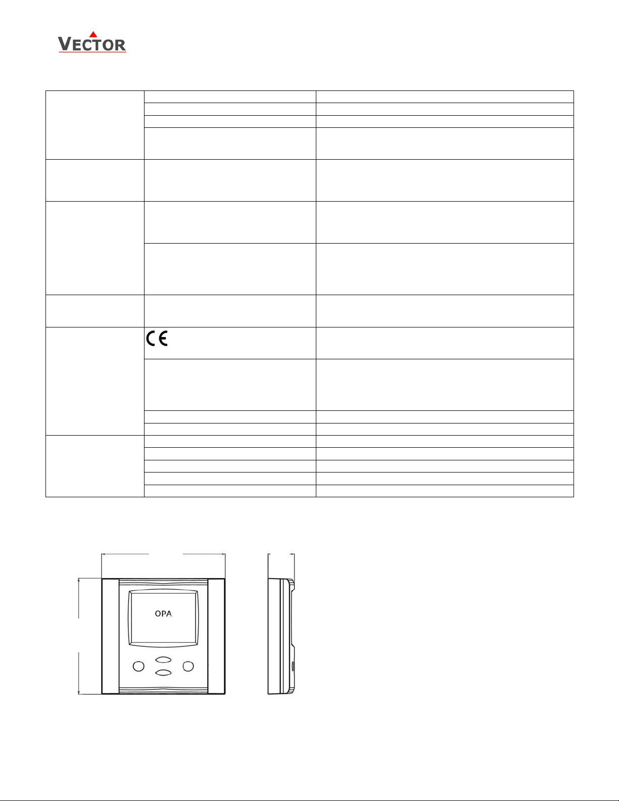
General Dimensions (H x W x D) 88 x 88 x 21 mm (3.5 x 3.5 x 0.8 in)
Housing Material Fire proof ABS plastic (UL94 class V-0)
Mounting Plate Zinc coated steel
Standard Color White RAL 9003
Weight (including package) 130 g (4.6 oz)
Dimensions
VPP (Vector Proprietary Protocol)
Copper wire 4 x 0.8…2.5 mm
Unshielded 20 m, Shielded > 50 m
4 digits
0.1
1
ON, OFF
To IEC 721-3-3
class 3 K5
0…50 °C (32…122 °F)
<95 % r.H. non-condensing
To IEC 721-3-2 and IEC 721-3-1
class 3 K3 and class 1 K3
-25…70 °C (-13…158 °F)
<95 % r.H. non-condensing
class 2M2
VPP (Vector Proprietary Protocol)
Twisted pair 0.5mm
Unshielded 20 m, Shielded 50 m
EN 61 000-6-1/ EN 61 000-6-3
EN 60 730 –1
EN 60 730 – 2 - 9
2
, max 400 pF capacity
2
.
88 (3.5)
88 (3.5)
21
(0.8)
Doc: 70-07-0171, V1.3: 20100421 Vector Controls GmbH, Switzerland Page 2
Subject to alteration
Page 3

6
Remote display OPA-S
Display and Operation
The OPA-S terminal is designed with a modular casing structure. The user has the choice of a variety of designs
and materials. See separate brochure for details regarding different styles, colors and materials of operation
terminals.
The operation terminal uses an LCD display and four operation buttons.
5
1
6. Buttons for operating the controller:
LEFT key: Operation mode (On, Off) Not used
UP key: Display Maximum values, pressing for more than 2 seconds resets Maximum value
DOWN key: Display Minimum values, pressing for more than 2 seconds resets Minimum value
RIGHT key: Select transmitter, For transmitters with more than one input.
Operation of the Terminal Unit
Idle display
Used for combination transmitters (Temperature and Humidity, Temperature and Pressure). This display mode
is active if no key has been pressed during the previous 30 seconds. The current temperature is displayed in
the large digits and the humidity or pressure is displayed in the small digits.
Pressing the RIGHT key will step through available sensor inputs, indicating the current, minimum or maximum
value in the large digits and input number in the small digits and the output signal in the vertical bar.
Indication and reset of minimum and maximum values
Activate the desired transmitter for dual transmitter by pressing the RIGHT key. Press UP to display Maximum
values, press DOWN key to display minimum values.
Resetting minimum or maximum values: Pressing either UP or DOWN keys for longer than 3 seconds while the
minimum or maximum values are displayed.
Error messages
The OPA-S may display the following error condition:
Err1: Communication time out between terminal unit and transmitter. Terminal unit will reset after 10
seconds.
Err2: Temperature sensor faulty. The connection to the temperature sensor may be in terrupted or the
temperature sensor is damaged. As a consequence the output of this transmitter are switched off.
Legend:
1. 4-digit display of current value, Minimum,
2
3
4
Maximum or control parameter
2. Unit of displayed value, °C, °F, % or none
3. Graphical display of output or input signal
with a resolution of 10%
4. 4-digit display of current value or control
parameter
5. Left bar = display of minimum value
Right bar = display of maximum value
Doc: 70-07-0171, V1.3: 20100421 Vector Controls GmbH, Switzerland Page 3
Subject to alteration
Page 4

Remote display OPA-S
Installation
1. Install the mounting plate straight to the wall or the flush mounting box. Make sure that the nipple with
the front holding screw is facing to the ground. Make sure the screw heads do not stand out more than
5 mm of the surface of the mounting plate.
2. Connect the wires of the terminals to the communication wires according wiring diagram
3. Slide the two latches located on the top of the front part into the hooks of the mounting plate.
4. Lower the front part until located flat on the wall and the mounting plate is not visible anymore. Make
sure the connection cable does not get into the way.
5. Tighten the front holding screw to secure the front part to the mounting plate.
Connection to Base Unit
• Max. Distance: 50 m using shielded copper wire
• Always use shielded copper wire if distance > 20 m and electro magnetic interference is present.
Setting of configuration parameters
Intelligent sensors can be adapted to fit perfect into your application. The preparation of the sensing signal is
defined by parameters.
The parameters are password protected. The parameters can be changed as follows:
1. Press UP and DOWN key simultaneously for three seconds. The display will indicate CODE.
2. Select a password using UP or DOWN keys. Dial 0009 in order to get access to the configuration
parameters. Press the RIGHT key after selecting the correct password.
3. Once logged in, choose IP for input configuration or OP for output configuration using UP or DOWN.
Press the RIGHT key after selection.
4. The parameters are now displayed. The small digits show the parameter number, the large one its value.
5. Select the parameters with the UP/DOWN keys. Change a parameter by pressing the RIGHT key. The
MIN and MAX symbols show up and indicate that the parameter may be modified now. Use UP and
DOWN key to adjust the value.
6. After you are done, press RIGHT or LEFT key in order to return to the parameter selection level.
7. Press the LEFT key again so as to leave the menu. The unit will return to normal operation if no key is
pressed for more than 5 minutes.
8. The parameters and its values depend on the transmitter. Please use the respective datasheet for the
list of parameters
Electrical connections
Normal cables maybe used for wiring in an EMC-save environment. In an extremely impaired EMC environment
use only shielded cables.
The operating voltage must comply with the requirements for safety extra-low voltage (SELV) as per
EN 60 730. Connect the cable using the four-pin plug provided.
Doc: 70-07-0171, V1.3: 20100421 Vector Controls GmbH, Switzerland Page 4
Subject to alteration
 Loading...