

Page 1
Page 2

Page 3
MP
ror
MATRIX
PRIN~..-R
Revision
USER•S
Revision
July
1
MA.~1JAL
B
7,
1980
Copyright
1980
Vector
Graphic
Inc.
Page 4
Vector
contents
covered
D."1e
right
in
the
person
exists.
The
date
page.
improved
date
and
recently
product
and
the
product.
TITLE
PAGE.
Graphic
of
by a
to
content
of
such
and
The
revision
but
revision
revised.
will
manual
EACH
makes no
this
ma..'1ual
warranty
revise
hereof
revision
revision
the
get
a
will
IvlAJ.'IDAL
Copyright
itself,
or
this
without
or
of
letter
PRODUCT
on
the
When
new
revision
revert
SHOULD
1980 by
All
rights
Disclaimer
representations
lNnether
repair
agreerrent.
pUblication
obligation
changes,
Revisions
each
such
itself
Title
the
page
as
A
has
Page
product
number,
to
revision
ONLYBEUSED
Vector
Graphic
reserved.
or
or
not
Further,
and
to
make
except
wnen
herein
or
B
changes
not
been
corresponds
itself
as
shown on
A,
as
WITH
Inc.
warranties
the
product
changes
of
Vector
an agreement
appears
if
significantly
to
is
modified
the
if
it
were
THE
PRODUCT
with
Vector
from
Graphic
at
the
that
manual's
treating
respect
it
describes
Graphic
time
to
the
bottom
MANUAL
to
the
reserves
to
notify
contrary
has
rrodified.
of
the
page
significantly,
title
a
brand
IDENTIFIED
to
of
ON
the
is
time
any
each
been
The
most
the
page,
new
THE
Rev.
I-B
6/7/80
Page 5
Vector
Graphic
MP
Dot
Matrix
Printer
The
MP
Dot
Matrix
and
without
warranty
of
any
fitness
notwithstanding,
days
Printer
following
that
provided:
1.
Such
MP
Dot
Matrix
2.
VEC'IOR
claimed
GRAPHIC,
INC.,
replacement
P~pair,
which
performed
Matrix
INC.,
wi~~in
3.
INC.,
to
confirm
if
replacement
are
discovered
by
Printer
for
such
replacement
will
Buyer
VECTOR
is
$35.00
required
correction
of
the
submit
GRAPHIC,
estimate
signed
to
commence
obligation
no
the
written
GRAPHIC,
repair
be
GRAPHIC,
for
thereafter.
of
period
to
Buyer
INC.,
of
charges
by
duly
with
estimate
INC.,
charges
warranty,
VEC'IOR
delivery
is
found
defect
Printer
GRAPHIC,
ten
(10) days
The
MP
at
the
found
V"EC'IOR
is
repair,
or
correction
charged
INC.,
the
first
defects
for
a
written
will
authorized
the
to
repair,
may
prior
:REPAIR
Printer
for
left
sold
either
intended
GRAPHIC,
to
customer,
to
contain
in
material
the
\lEC'IOR
expressed
use
INCqwill,
INC.,
after
Dot
Matrix
customer's
alleged
to
be
in
or
correction
after
GRAPHIC,
returned,
Printer
expense,
defect,
order.
expiration
INC.,
also
replacement
after
in
addition
repair
hour,
in
material
Prior
rate.
and
to
no-cost-to-Buyer
estimate
not
commence
has
been
returned
representative
repair
work
involved.
replace
has
been
returned
at
its
option
to
commencing work.
AGREEMENT
hereunder
is
or
or
merchantability.
repair
defects
or
workmanship
in
GRAPHIC,
is
given
its
discovery;
notice
is
promptly
for
and
of
any
defects
of
the
at
Buyer's
at
Buyer's
or
correction.
ex~iration
to
the
cost
At
the
present
$18.00
per
commencing
or
workmanship
repairs,
of
the
expected
repair
by
until
Buyer
authorizing
V"EC'I'OR
or
correct
with
also
any
approval
require
sold
~~plied,
for
or
"as
including
a
period
replace
is",
materials
existed
INC.,
factory;
of
returned
examination
for
subsequent
in
material
period
expense,
set
provided
expense,
In
performing
of
the
period
of
parts
time
hour
any
for
repair,
discovered
VECTOR
charges,
such
to
VECTOR
VECTOR
GRAPHIC,
MP
Dot
Matrix
to
proceed,
prepayment
with
any
However,
of
ninety
any MP Dot
or
workmanship,
at
the
the
precise
by
V"ECTOR
or
workmanship
for~~
the
every
to
VECTOR
set
the
then-current
applicable
hour
above
forth
replacement
after
GR~PHICr
time
as
GRAPHIC,
GRAPHIC,
INC.,
Printer
of
the
all
faults
Luplied
the
above
Matrix
time
defect
to
VECTOR
GRA.!:-tHC,
repair
will
the
MP
GRAPHIC,
any
repair,
above,
of
work
expiration
INC.,
and
V~CTOR
the
written
INC.,
INC.!
shall
until
and
VECTOR
estimated
(90)
the
or
be
Cot
rate
or
will
have
Repair
Agreement
GRAHUCgINC.
Rev.
I-B
6/7/80
within
void
ten
if
the
(10) days
enclosed
of
end consumer
card
is
not
purchase.
returned
to
VECTOR
Page 6

Page 7
Vector
Graphic
FOREWORD
MP
Dot
Audience
Matrix
Printer
'Ibis
manual
distributors,
moderate
technical
computers.
is
intended
or
others
knowledge
for
with
computer
at
least
of
srrall
a
Scope
Organization
It
will
MP
of
both
systems,
Each
of
WHAT
describe
Dot
Matrix
a computer
in
Vector
and
section
technical
the
printer
Printer
system,
Graphic
how
is
written
depth.
moderate knowledge
nUseris
MP
level
a
fe-w
discusses
knowledge
software
and
Guide"
make
of
knowledge
simple
\~
of
principles
describes
it
work and assumes
tools.
the
digital
what
the
does
how
the
printer
"Perspective"
does
and
of
computer
plus
"Theory
board
electronics
and
Vector
in
to
in
the
use
other
Graphic
context
G~e
printer
8-100
works.
at
a
uniform
level
describes
requires
only
design.
HCW
to
install
the
same
the
ability
of
Operation"
to
use
works and assumes a
and
a
the
Rev.
l-B
6/7/80
Page 8

Page 9

Vector
Graphic
MP
Dot
Matrix
Printer
Section
Table
Specifications
1.
Perspecti
leI
1.2
1.
1.4
II.
User's
2.1
of
Contents
ve
CoInpatibility~
Modifications
3
Sc>f
t:tvare
Dr*
Reliability
i
ver'"
and
Illt
to
Guide
Modifications
2.1.1
2.1.2
2.1.3
2.1.4
Power
Bitstrearner
Bitstreamer
Installing
to
supply
TABLE
.....
f>"
l1'ainframe
....
~
'I!I
fJiIl
Ii!'
•~• 0
OF
CONTENTS
1lII
4'1
I'il
'"
fl
l:I.t!l
••••••.••••••••••••••••••••••••••
..
m (II " III
cost-effectiveness
the
mainframe
modifications
I
board
II
the
modifications
board
PROM
on
modifications
..
11\
<ll
O!II
'"
Ill"
<Il
III III
Ill.
1lII•'"
ID;III
......
1lII
olIln"I'l
O!JI'"" •
.,
1Il~..
1\\",e
""
<Ill"..
'!I
'"
of
the
printer
••••••••••
•••••••••••••••••••••••••••••
••.•••••••••••••••••••••••
••••.••••••••••••••
••••••••••••••••••
b~e
PROM/pAM
board
•••••••••••
"'
...
III"
41"
""
",1-1
l-l
1:1I
41>
iIIl
f!'"•
oft
!\\
41-1
1-2
2-1
2-3
2-4
2-6
2-7
III.
2" 2
Cable
203 Loading
2",
4
Initial
2.4.1
2.4.2
2.5
Printer
2.5.1
2.5.2
2.5.3
2.6.1
2.6.2
2.7
Special
Theory
3.1
3.2
of
Print
Line
Operation
feeding
hook
up.
Paper
Testing
Testing
Testing
Control
Printer
Printer
Printer
Changing
Periodic
Graphics
wire
firing
-1'1
•~•'"• e
....
""
III
the
the
COIl1ITlClnds"'~!'l~~*"'~"""""
Control
Control
Control
Ribbons~.olIlI!llQe
Lubrication
lIIl
•
II)'"•
.,
~
l\I
II!I"I'" '"
,00)
II!'
!III
<Ill
l!t
tl
ifl
III III'"..
CII
~
III 'fl
MP
and
printer
MP
and
printer
COIl1ITlClnds-MDOS
COIl1ITlClnds-CPjM
Commands-Basic
•••••••••••••••••••••••••••••••••
Characters
••••••••••••••••••••••••••••••••
«I
l!l""o!!I
l!I I'!I
jI
"
""
•
III
11II
~
!III'".,
:flo
"
1'1
fl
I!Il • II!
'"
l!I III • III
III
II
t'l
""
o!Il
e
'3
Q
IlIl~" •
II)"..
11
eA
driver
driver
••
under
under
fllo)lIlil'l"'.Il\."l
MDOS
CP/M
•••••••••.••••••••••••••
••••••••••••••••••••••••
•••••••••••••••••••••••
••
~~e~~~~~••~••~••~~o~
'I!I
11II
III • III ".." lit
fit I!l l!I
•••••••••
•••••••••
~'*.C1.at1l2-9
•••
~.4~~e2-12
••••••••.•••••••••••••••••.••••.••••••••••
IIIIl'"G • jI(l
<\II
•
/l!l
'"
III e
""••'"
•
olJI
..
iii!~"" ""
(!!J""""
IliIl"""
.....
"
.\II
• "II 0
__
'II)
II
III
"':l
•
<!II
lIo
2-
7
II!l
e,
..
f!l
2-8
'"
il'I
2-8
2-9
2-9
2-l0
2-10
2-1l
2-13
2-12
3-1
" III
III
<II
l!ll
3-2
Rev.
1-8
6/7/80
Page 10
IV. Appendix
4.1
Function
4.2
Graphics
4.3
4_4
Printing
other
Graphics
Ribl::on
First
Second
Schematic
of
[Tci
under
print
OLiver
Setting
Interval
InteDlal
Vector
Graphics
ver
Program
functions""."t'lle~.~"'''''''''''e'".I!IIIlI'''09'''~''''I'I''~
OLiver
Corrrrnands.;,
Control
PRCM
0
••••••
•••••••••••••••••••••••••••••
Graphic
HP
Ibt
Matrix
•••••••••••••.•••••••••••••
,
••••••••••••••••••••••••••
....
1lI
...
<lII'''o'''~'''-I!IIlIlft4-2
Printer
4-l
4-4
4-1
Listing-Supplemental
Instructions-Supplemental
Lubrication
Lubrication
Points
Points
Rev.
I-B
6/7/80
Page 11
Vector
Graphic
MP
Dot
Matrix
Printer
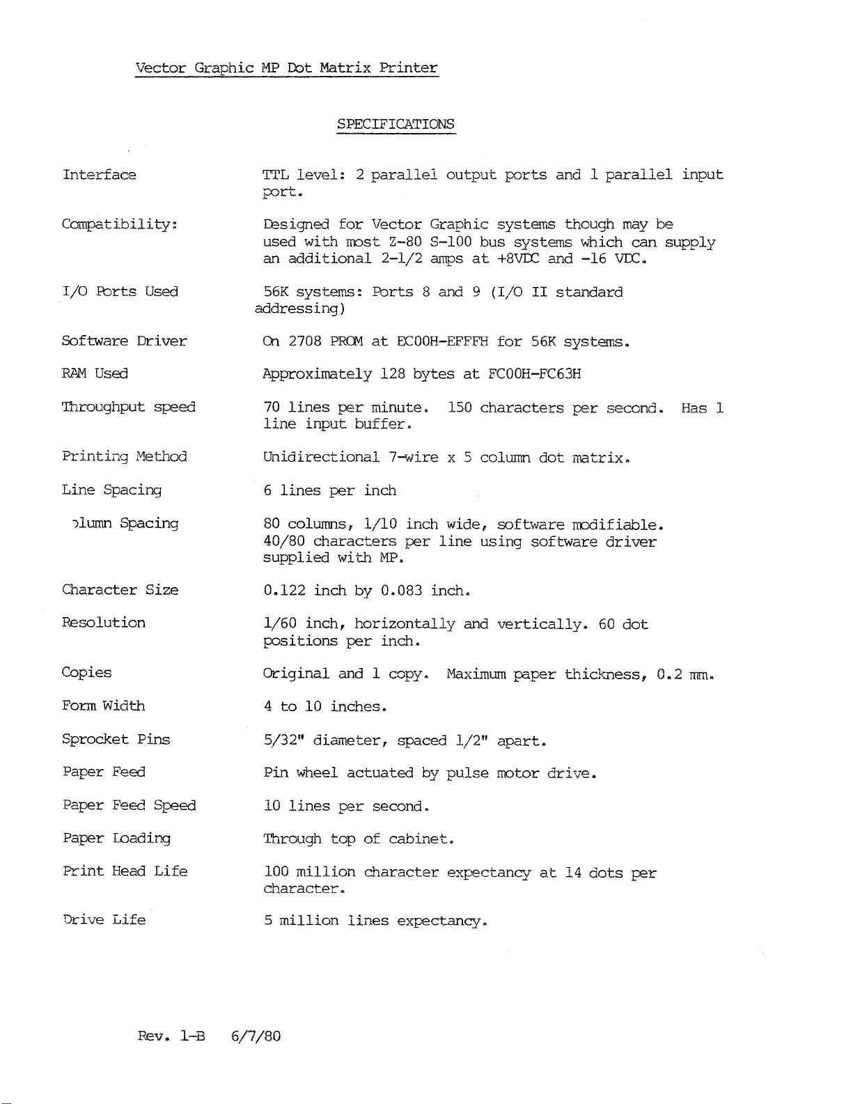
SPECIFICATIONS
Interface
Compatibili
I/O
:tbrts
Software
RAM
Used
Driver
Throughput
Printing
Line
)lumn
Method
Spacing
Spacing
ty:
Used
speed
Tl'L
level:
port.
Designed
used
an
additional
56K
systems:
for
wiL~
most Z-80 S-lOO
addressing)
On
2708
PROMatECOOH-EFFFH
Approximately
70
lines
line
per
input
Unidirectional
6
lines
80
40/80
supplied
per
columns,
characters
with
2
parallel
Vector
2-1/2
Ports
128
minute.
buffer.
7~ire
inch
1/10
MP.
Graphic
amps
8 and 9
bytes
inch
per
output
systems
bus
at
+8VDC
(I/O
for
at
FCOOH-FC63H
150
characters
x 5 column
wide,
line
software
using
ports
syste~
and 1
and
II
standard
56K
dot
software
parallel
though
may
wnich
-16
VIC.
systems.
per
second.
matrix.
modifiable.
driver
can
input
be
supply
Has 1
Character
Resolution
Copies
Form Width
Sprocket
Paper
Paper
Paper
Print
Drive
Feed
Feed Speed
Loading
Head
Life
Size
Pins
Life
0.122
1/60
inch
inch,
positions
Original
4
to
10
5/32"
Pin
10
diameter,
wheel
lines
Through
100
million
character.
5
million
by
0.083
horizontally
per
inch.
and 1 copy.
inches.
spaced
actuated
per
second.
top
of
cabinet.
character
lines
expectancy.
inch.
and
Maximum
1/2"
by
pulse
expectancy
v~rtical1y.
J?Clper
60
thickJ.'1ess,
apart.
motor
drive.
at
14
dots
dot
per
0.2
Imn.
Rev.
I-B
6/7/80
Page 12
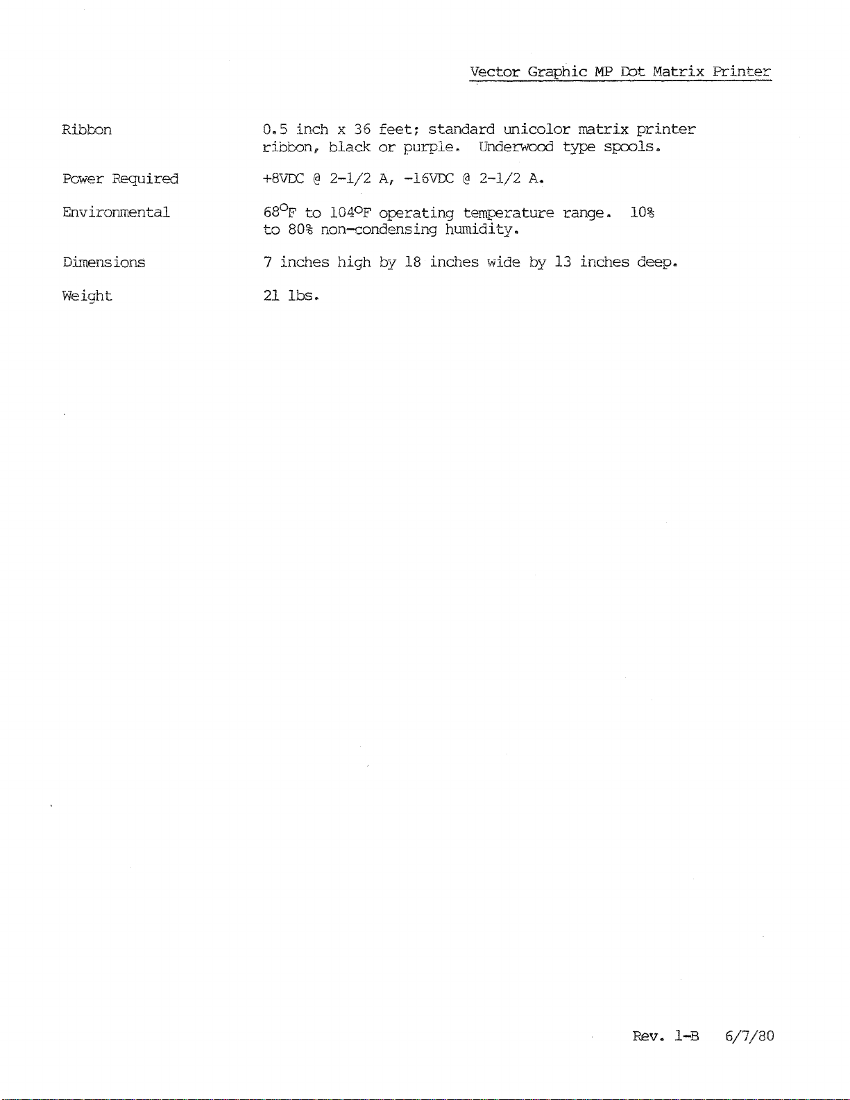
Ribbon
0.5
inch
ribbon,
x 36
black
feet;
or
standard
purple.
Vector
unicolor
Underwood
Graphic
type
MP
matrix
spools.
Dot
printer
Matrix
Printer
Power
Required
Environmental
Dimensions
Weight
+8VLC@2-1/2
68
to
7
21
0
p
to
80%
inches
Ibs.
0
l04
non-condensing
high
A,
-16VTC@2-1/2
p
operating
by 18
temperature
humidity.
inches
A.
wide by 13
range.
inches
10%
deep.
Rev.
I-B
6/7/80
Page 13
Vector
1.1
Compatibility
printer.
Graphic
system
output
1.2
Modifications
modifications
particularly
The
If
Graphic
Vector
'Though
microcomputer
which
ports
has
and
to
your
printer
if
MP
Ibt
Graphic
the
at
least
can
mainframe
was
may
it
was
Matrix
MP
MP
is
was
Printer
designed
system,
one
supply
2-1/2
may
ordered
be
necessary
manufactured
I.
PERSPECTIVE
a low
cost,
it
parallel
amps
be
required.
separately
prior
tractor
specifically
can
be
TTL
at
+8VDC
and
on
your
to
used
input
not
Vector
1/1/80.
with
and
feed,
for
80 column
use
any
port,
-16VDC
part
ofacomplete
Graphic
wi
S-lOO
two
to
dot
th
any
Z-80
parallel
the
printer.
mainframe,
matrix
Vector
based
TTL
syste~,
1.3
Modifications
into
the
Software
software
routine
routine
will
96
are
supplied
the
back
All
parts
The
Vector
include
standard
possible
power
panel
Driver
driver
is
as
with
programming.
appendix
support
The
without
of
for
printer
modification,
microcomputers
Simply
provide
follow
printed
which
supply,
and
necessary
Graphic
resident
necessary.
part
of
this
ASCII
via
the
A
this
special
driver
operating
the
output.
may
installing
installing
for
MP
in
Vector
the
CON"FIG
routine
characters,
direct
system
provides
listing
manual.
graphics
supplied
on
with
appropriate
be
required
a
PRQ'1onthe
the
modifications
dot
matrix
RAL'1.
rrodule.
as
an
an
assembly
of
the
An
MP
characters.
with
Vector
the
include
a
cable
printer's
In
addition,
Graphic
overlay
alrnost
language
character
printer
Graphics
the
Graphic
fol1017ing
print
wiring
between
PRCM/RAM
are
included
features
a
CP/M
Vector
file
endless
2.X
Graphic
called
array
software
generation
driver
Driver
MP
dot
HZ, System
sofrware:
instructions
small
diskettes
routine
PROM
matrix
a
printer
the
board.
wiG~
are
printer
MOOS
SYSP.
of
graphics
control.
and
printer
B,
3030
MOOS,
with
power
interface
the
controlled
driver
include
8.6
Besides
other
is
included
provides
and Mernorite
MZOS
the
outlet
board
printer.
diskettes
printing
characters
The
necessary
software
will
and
software
and
by a
access
this
PROM
in
the
work,
II
CP/M.
to
While
routine
undertaken
Note:
or
Rev.
You
later).
I-B
it
is
to
operate
by someone
must
6/7/80
certainly
with
have
D.~e
possible
other
familiar
4.
0
systems,
with
monitor
to
Z-80
to
modify
this
assembly
run
the
is
or
a
r'IP
job
rewrite
which
language
if
us
ing
the
printer
should
programming.
MlXlS
(vers
driver
only
ion
be
8.
1-1
6
Page 14
1.4
P£liability
effectiveness.
ccmputer
to
Graphic
The
offer
and
cost
Vector
al'D
Graphic
deriving
a compact
microcomputer
effectiveness
MP
Dot
Matrix
This
was accomplished by
fOwer from
printer
at
a
which
truly
Vector
of
the
printer.
Printer
is
driving
the
mainframe.
is
eminently
advantageous
Graphic
clearly
the
printer
This
compatible
price.
M2
Dot
Matrix
a
breakb~rough
permits
with
from
Vector
the
your
Printer
in
cost
host
Graphic
Vector
Considerable
elimination
absorbant
In
addition
Printer
has
printer
life
expectancy
The
MP
firmware,
completely
of
material
proven
drive,
Dot
Matrix
installation
factoDJ
attention
noise.
to
reduce
to
the
to
be
for
example,
is
estimated
Printer
assembled and
was
It
features
machine
above
remarkably
is
to
instructions
given
an
features,
reliable.
estimated
be 100
comes
tested.
during
enclosure
vibration
the
to
million
complete
and
design
of
the
specially
and
resultant
Vector
The
be
5
Graphic
life
million
characters.
with
all
documentation.
printer
treated
noise.
MP
expectancy
lines.
necessary
The
Witl1
Dot
Print
cables,
unit
to
the
sound
~~trix
of
the
head
is
1-2
Rev.
l-B
6/7/80
Page 15

Vector
dot
is
current
exploiting
Inc.
performance
2.1
Modifications
Graphic
In
order
matrix
not
is
to
printer
intended
loop
signals
the
able
to
to
MP
Dot
understand
was
to
inherent
offer
your
to
the
Matrix
designed
be
a
directly,
a
dot
system
Vector
Printer
II.
USER'S
the
UserI s Guide, you must be aware
to
free
standing
for
capabilities
matrix
at
low
cost.
Graphic
GUIDE
work
as
part
unit.
example.
of
the
printer
that
Microcomputer
of
a
By
Z-80
It
cannot
taking
based
this
Z-80, however,
can
deliver
handle
approach
Vector
exceptional
that
the
system,
RS-232
Graphic,
MP
it
or
and
This
section
mainframeI s power
are
going
an
JvI.P
However,
Graphic
to
printer,
computer
use
THIS
if
interconnecting
There
diskette,
of
the
rear
the
computer
supplied
installed
1)
The
the
other
supply
2) A
on
one
Bitstrearner
are
four
and and a two PRQII I s
cables
panel
of
are
the
to
for
on
the
four
in
25
conductor
end
wire
ends
the
and
is
mainframe
I/O
describes
supply
the
to
printer
SECTIONISVERY
the
printer
system,
cables,
cable
used
you
assemblies,
to
connect
canputer.
the
MP
dot
use
with
PROM/RAM
cable
used
board.
with
to
to
flat
cable
a 24
board
pin
to
the
the
modifications
accomodate
in
an
was
aside
may
skip
supplied
Two
matrix
the
Bitstreamer
a Molex-type
make
the
power
rear
wnich
DIP
connector
bac..1<
the
existing
JJl1EORTANT.
shipped
from
the
directly
a
small
with
from
are
sources
used
printer.
available
panel
of
terminates
on
panel
of
printer
system
as
a
section
to
adapter
the
inside
to
connect
The
II
I/O
plug
on one end and
the
in
the
other
the
computer.
which
's
must
power
that
part
of
on
the
test
printed
MP
dot
the
from
small
board.
from
computer.
a DB-25S
is
be
needs.
was
not
a
complete
plugging
section.
circuit
matrix
computer
the
adaptor
The PROM's
the
internal
female
used
made
shipped
printer.
back
spade
connector
to
connect
to
If
Vector
in
board,
to
panel
board
lugs
power
the
you
with
the
a
'I\vo
the
of
is
are
on
the
3)
The
cable
the
4)
other
The
is
flat
and a female
the
mainframe
5) The
socket
second
Rev.
adaptor
on
cable
1-B
the
with
used
cable
DB-25S
to
board
other
listed
6/7/80
a
to
connect
which
connector
the
MP.
with
is
above.
female
two 34
used
Molex-type
the
power
terminates
on
the
pin
to
connect
connectors
supply
in
a male ffi-25S
other
is
sockets
the
Bitstreamer
in
used
on
on one end and a male on
the
one
mainframe
connectors
to
provide
side
II
and a
I/O
to
signals
24
board
the
on
pin
MP.
one end
from
DIP
with
the
2-1
Page 16

~
----=.-.
=-=.
===~-=-=_._=-=~~=;~
---
«(\9+)
"
L-
~O_lt?Vd"':J
"}:j;lWl!lodsNv:,U
_
N..o11'1},
,(
'
Q;J}d
1\"1--)
..
\
N\l'.::I
,'1
I
'"
Page 17

Vector
Graphic
MP
COt
Matrix
Printer
2.1.1
Bower
wired
In
Supply
order
into
computer.
1)
Unplug
cord
2)
3)
Wait
fran
at
Unscrew
screwdriver.
right
side
capacitors,
4) Make
sure
disconnected
5)
Thread
out
in
the
computer
this
6)
Identify
has
Loosen
attached
the
not
section.
white
the
to
spade
Modifications
to
run
the
mainframe power
A
separate
the
microcomputer
the
back
of
least
the
one
4
screw~
Remove
of
the
computer
two
stud-ty~
at
least
the
power and have
the
four
back
of
manufactured
capacitor
wires
minus
it)
lug
going
terminal
and
attached.
the
cable
the
minute.
the
wires
b~e
C2.
fasten
MP
dot
then
from
machine.
which
cover.
and
diodes
one
minute
of
machine.
by
Vector
It
to
one
on
this
the
Tighten
matrix
supply
connects
the
hold
The
consist
and a
taken
the
power
If
is
one
terminal
capacitor
yellow
the
printer,
&ld
b~en
the
mainframe
outlet
the
power
cover
and
to
supply
ofatransformer,
has
the
bridge
elapsed
rectifier.
cover
cable,
you
are
interfacing
Graphic,
of
the
and
Inc.
two
yellow
(the
wire
of
the
terminal.
a power
fastened
disconnect
the
frarre
components
between
off.
lug
ends
see
28,000
wires
one
with
MP
power
supply
to
to
first,
the
the
mfd.
the
the
the
using
three
the
MP
note
capacitors
going
the
cable
cable
rear
must
of
the
printer.
power
a
Phillip's
are
supply
on
the
electrolytic
time
you have
throughacut
to
an
3-100
at
b~e
end
and
to
the
other.
yellow
to
it
wires
using
be
of
7)
Identify
terminal
white
of
wires
remaining
white.
8)
wires
minus
it)
lug
9)
should
10)
may
already
options:
may
required
CO);\jNECIDR.
Tighten
Identify
going
terminal
and
fasten
attached.
You
may
be
If
you
permanently
have
you
cut
a
are
capacitor
C3
has
red
two
going
wires
the
to
of
terminal.
capacitor
to
one
terminal
on
~~is
the
purple
Tighten
test
the
approximately
have
an
appropriate
fasten
such
may
hole
.600
"
leave
in
inch
a
the
C3.
wires
it.
the
MP
Cl.
It
capacitor
the
terminal.
voltages
+8VTC.
the
hole
the
connector
back
by
.725
It
is
attached
Loosen
power
is
one
and
purple
(the
wire
of
at
Pin3should
connector
in
the
panel
inch.
the
both
cable
of
one
the
the
cut
back
hanging
yourself.
60,000
to
it,
these
to
28,000
wires
with
MP
power
connector.
out
in
to
the
panel
Label
mfd.
the
capacitor.
minus
terminals
them:
mfd.
going
the
cable
red
capacitors
to
the
purple
to
Pin
be
approxL~tely
the
rear
of
rear
of
loose
this
panel.
your
computer,
out
The
dimensions
connector
terminal
and
to
red,
and
other.
wires
it
using
2
is
-16VDC.
your
mainframe,
If
of
the
"PRINTER
The
plus
of
C3
fasten
white
has
white
Loosen
attached
the
spade
gro~~d.
you
Pin
do
you have two
back
of
or
the
POWER
hole
has
the
to
the
to
1
you
not
you
P-.ev.
I-B
6/7/80
2-3
Page 18

If
you
computer
yellow
your
+8V
ground.
are
interfacing
which was
wire
of
source,
G1.e
the
the
not
manufactured
power
cable
purple
Vector
asse.mbly
wire
Note:
Graphic
by
to
your
Vector
MP
Vector
to
your
+16V
Graphic
dot
matrix
Graphic,
-16V
source,
MP
Ibt
printer
Inc.,
source,
and
the
Matrix
connect
the
'Nhite
to
red
Printer
an
S-lOO
wire
wire
the
to
to
2.1.2
Bitstrearner
In
order
system
traces
via
must
Bitstreamer
left
switches
hand
in
printer
Bitstreamer
1)
On
the
10
of
U17,
and 7. Cut
2)
On
the
J3.
pad 19
3)
On
20
of
4)
On
5)
Plug
I
board.
IB-258
this
Cut
this
the
J2.
the
of
in
connector)
purpose.
I Board
to
interface
the
Vector
be
I
board
side
D1.e
to
a
Vector
II
I/O
canponent
runs
this
circuit
trace
circuit
circuit
J2.
the
cable
Fasten
Label
Modifications
a
Vector
Graphic
cut
and
bllo
jumpers must
may
be
identified
of
the
board.
same
position.
Graphic
board,
side
undernea~1.
go
of
to
the
and
trace.
side
of
the
board,
at
the
pad.
side
of
the
l:xJard,
side
of
the
l:xJard,
to
with
the
the
this
the
other
back
connector
end
Graphic
Bitstreamer
by
The
Bitstreamer
If
you
microcomputer
the
next
l:xJard,
exits
from
there
solder
solder
24
pin
DIP
of
the
panel
through
"PRINTER
MP
dot
matrix
I
board,
be
~~e
added
single
as
per
DIP
II
are
interfacing
which
section.
there
is
beneath
is
a
a
trace
the
trace
a jumper from pad 8
a
jumper
connector
cable
one
SIGNAL
to
assembly
of
the
CONNECTOR.
printer
two
the
switch
board
the
is
which
chip
which
from
J3
of
(terminating
cut
to
printed
following.
on
has
MP
dot
equipped
begins
between
runs
to
of
pad
17
the
Bitstreamer
outs
provided
II
an
circuit
the
three
pad 8
J3
of
S-lOO
'The
upper
DIP
matrix
with
at
pin
pins
to
pad
J3
in
for
a
6
of
to
an
Note:
2-4
Make
sure
that
the
original
port
addresses
have
not
been
Rev.
changed.
l-B
6/7/80
Page 19
,n
I
('1
-i:iNVd
),IV3"2:1
~O..L:J3NNO':J
a.L
(:I'EIN3J
Sg
rc
.tod
I
Page 20

Vector
Graphic
MP
Ibt
Matrix
Printer
2.1.3
Bitstreamer
Bitstreamer
1)
board
orienting
panel.
2)
female
DIP
the
3)
cut
this
BITSTREAMER
If
you
At"1
adapter
to
Take
connector
socket
plug
Attach
outs
connector
SCCKET
are
the
the
are
at
II
interfacing
II
board,
two
the
cable
on
on
the
the
"PRINTER
II
Board
Modifications
use
board
board
34
has
pin
so
which
attached
the
adapter
the
same
connector
back
panel
IB-25
CONNECTOR
the
t..~e
following
been
connectors
that
has
to
the
board.
end.
on
the
;,vhich
SIGNAL
SIGNAL
Vector
Graphic
procedure.
suppl
the
a
24
24
other
ied
on
pin
top
pin
DIP
end
Make
other
has
end
been
CONNECTOR."
CABLE
PIN our
24 PIN DIP
SCCKET
MP
with
the
of
DIP
socket
plug
and
plug
sure
of
the
the
provided
DIAGRZIM
dot
MP.
the
on
notches
cable
for
matrix
printer
Connect
Bitstreamer
is
towards
one
end
the
DIP
on
to
one
this
purpose.
FORI'
with
the
adapter
II
board,
the
and
an
plug
the
of
into
socket
the
DESCRIPrION
the
rear
DB-25S
the
and
blank.
Label
J4J4J4J4J4-11
J4-12
J5J5J5J5J5-
J5J5J5-
*
J4
Note:
system
and
9 (factot"l.l
2*
3
4
5
2
3
4
5
6
7
8
1
is
Make
using
the
left
sure
the
standard.)
18
19
22
23
8
21 8
17
16 3
15
14
24
25
12
11
h&"1d
the
I/O
socket
original
II
board,
on
port
the
top
of
addresses
parallel
10
17
11
12
13
14
the
l:;
..J
6
9
4
2
1
port
I/O
board.
II
have
not
addresses
AOO
AOI
A02
A03
AIO
All
BOO
BOI
002
B03
804
E05
806
E07
been
Step
Step
Step
enable
phase
phase
Motor
Timing
Home
Wire
Wire
Wire
Wire
Wire
Wire
Wire
1
2
3
4
5
6
7
Strobe
c~anged.
should
be
on
(top)
(bottom)
On a
set
A
B
56K
at
8
2-6
Rev.
I-B
6/7/80
Page 21

Vector
Graphic
MP
Dot I'1atrix
Printer
2.1.4
2.2
Installing
The
on
the
1)
You
24-pin
card
from
Check
2)
Install
PROM
matches
3)
Plug
4) The
Cable
Hook-Up
To
following:
1)
With
cable
back
panel
MP.
the
following
12K
Vector
may
identify
DIP
sockets
your
your
PR01/RAM
t...~e
the
the
PR01-RAM
PROM
installation
connect
the
(Molex
of
PROMonthe
instructions
Graphic
the
at
the
PROM-PAM
tell
PRa1-RAM
PROM-RN~
top
of
machine. Block B must
board
Printer
indicated
the
cables
power
at
connectors
the
mainframe
driver
back
the
manual
notch
into
is
now
between
mainframe
at
both
PR01
its
complete.
ends)
and
you
board.
the
for
in
on
socket
board
how
board
board.
be
details.
sock.et
the
the
to
the
to
install
in
With
addressed
11.
board.
on
the
computer
turned
the
printer
matching
the
your
computer
the
at
Make
motherboard.
and
off,
connect
PJwer
connector
Printer
fOwer
EOOOH
sure
the
at
DLiver
by
the
off,
for
the
remove
56K
notch
printer,
the
printer
connector
the
back
PROM
row
of
this
systems.
on
the
do
the
power
on
the
of
the
8
2.
2)
signal
the
matching
now
2.1
Connecting
If
following:
1)
and U21,
contains
socket
2)
the
3)
Fasten
provided.
With
cable
printer
canplete.
you
have
If
you
U20.
Place
ZCB
board.
Connect
the
the
power
(the
signal
connector
MP
a
Vector
have
install
a
2K
monitor
the
ZCB~~P
the
PB-225
flat
to
a
the
cable
at
2m
ZCB
at
the
mainframe
wide
connector
the
back
Board
Graphic
board
printer
.ROMinsocket
interface
to
the
connector
cable
of
which
driver
card
MP
to
still
with
on
system
the
the
a
back
MP.
equipped
contains
PRCMinsocket
U22,
on
the
Interface
one
of
turned
25
pin
panel
The
lK
place
parallel
and
the
connector
of
cable
with
monitor
U22.
the
port
to
the
cutouts
off,
the
hook-up
a
printer
rear
with
connect
at
mainframe
ZCB
PRQ~
If
your
socket
of
the
each
end)
procedure
board,
in
sockets
ZCB
driver
at
the
the
the
hardware
printer
from
to
the
is
do
the
U20
board
PROM
top
in
of
computer.
Rev.
I-B
6/7/80
2-7
Page 22
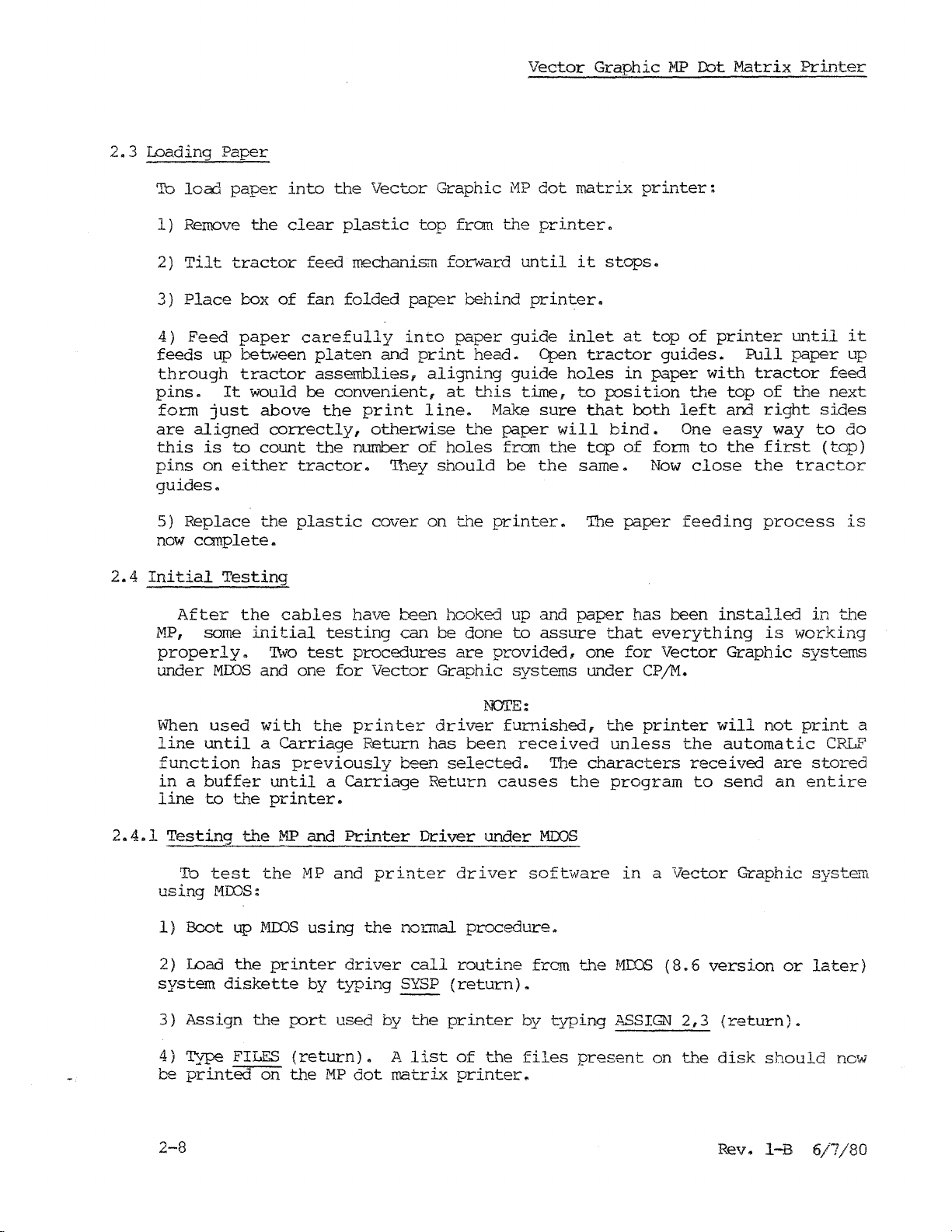
2.3
Loading
To
loac1
1)
Remove
2)
Tilt
3)
Place
4)
Feed
feeds
through
pins.
form
are
aligned
this
pins
guides.
up
just
is
on
Paper
paper
the
tractor
box
paper
between
tractor
It
would
to
either
into
clear
feed
of
fan
carefully
be
above
correctly,
count
tractor.
the
Vector
plastic
mechanism
folded
platen
and
assemblies,
convenient,
the
print
otherwise
the
number
They
Graphic
top
paJ?er
into
print
aligning
line.
of
should
from
forward
behind
paper
head.
at
this
Make
the
holes
Vector
HP
the
until
printer.
guide
guide
time,
paper
from
be
dot
matrix
printer.
it
inlet
Open
holes
to
sure
will
the
the
same.
Graphic
stops.
at
tractor
in
position
that
bind.
top
of
~1P
printer:
top
guides.
paper
both
form
Now
of
the
left
One
close
Dot
printer
with
to
Matrix
Pull
top
and
easy
the
until
paper
tractor
of
the
right
way
first
the
Printer
feed
next
sides
to
(top)
tractor
it
up
do
2.4
2.4.1
5)
Replace
now
complete.
Initial
After
MP,
some
properly.
under
When
line
MOOS
used
until
function
inabuffer
line
to
Testing
To
test
using
1)
2)
MOOS:
Boot
Load
system
the
Testing
the
initial
and
with
a
has
the
the
the
up
MIlOS
the
diskette
plastic
cables
'I\vo
test
one
the
Carriage
previously
until
printer.
MP
and
MP
using
printer
by
cover
have
testing
procedures
for
Vector
printer
Return
a
Carriage
Printer
and
the
driver
typing
been
can
been
printer
normal
call
SYSP
on
the
printer.
hooked up and
be
done
are
provided,
Graphic
NOTE:
driver
has
been
selected.
Return
Driver
causes
under
driver
procedure.
routine
(return).
to
assure
systems
furnished,
received
The
MOOS
software
frem
The
paper
that
one
under
the
unless
characters
the
program
the
MIDS
paper
has
everything
for
Vector
CP/M.
printer
in
a
(8.6
feeding
been
the
received
to
Vector
installed
Graphic
will
automatic
send
Graphic
version
process
is
working
systems
not
print
are
an
entire
or
is
in
the
CRLF
stored
systelTl
later)
a
3)
4)
be
2-8
Assign
Type
printed
the
FILES
on
port
used
(return).
the
MP
dot
by
the
A
list
matrix
printer
of
the
printer.
by
files
typing
present
~i\SSIGN
on
2,3
the
(re"turn).
disk
should
Rev. I-B
now
6/7/80
Page 23
Vector
Graphic
MP
Dot
Matrix
Printer
2.4.2
2.5
Testing
To
using
1)
Boot
2)
Type
choices.
YES
to
configure
3)
Type
Type
properly.
be
printed.
Printer
The
provided
sections.
under
1)
Tab:
the
test
CP/M.
up
CONFIG
In
the
itself
©P. 'This
a
few
Control
following
the
program
type
MP
and
the
HP
CP/M
using
(return).
response
question
words
By
typing
Typing
Commands
system
These
control
©I
or
Printer
and
printer
the
to
about
to
work
causes
of
your
DIR
©p
will
commands
has
commands
to
the
(tab)
Driver
normal
The
the
making
with
the
MP
choice
(return),
toggle
cause
been
perform
under
driver
procedure.
program
question
the
the
MP
to
print
a
the
the
initialized
will
~Nork
various
key.
software
will
about
selection
printer
to
confirm
list
print
MP
fran
CP/M
all
of
to
as
print
in
prompt
printers,
permanent,
every
data
input
that
the
files
function
perform
explained
the
keyboard
functions.
a
you
time
the
Vector
on
type
it
from
printer
on
on
and
the
in
the
or
various
the
is
your
off.
listed
they
Graphic
D. By
system
booted
the
keyboard.
is
operating
diskette
functions
following
can
system
system
ty-ping
will
up.
will
two
be
sent
2.5.1
2)
Line
3)
Form
4)
Carriage
5)
Toggle
6)
Toggle
(Works
7)
Toggle
8)
Set
top
9)
Set
form
increments.
and
12.
for
the
units
(Note:
'This
Printer
'Ib
use
feed:
feed:
type
type
©J
©L.
return:
auto.
CRLF
character/graphic
only
80/40
of
if
flag:
form:
MP
length:
For
values
These
values
position.
command
Control
the
Commands-MDOS
MP
under
or
type
flag:
Graphic
(ESC) and
(ESC)
(ESC)
are
works
MDOS,
(If)
©M
type
and
and
above
valid
'Ib
only
key.
or
(return)
(ESC) and
flag:
PRCM
~.
T.
Fxx.
99
only
set
a form
under
initialize
(ESC)
is
present:r
xx
lines
for
program
key.
~.
and
G.
designates
use
A, B
the
tens
length
of
control.)
the
system
form
andCto
place,
11",
as
follows.
length
they
xx=66j
in
represent
are
not
14",
xx=84.
1/6
inch
10,
valid
11
Rev.
I-B
6/7/80
2-9
Page 24

1)
B.
2)
Insert
Ty-pe
the
SYSP
diskette
(return).
(MDJS
8.6
or
later)
Vector
and
Graphic
boot
up
MP
the
D::>t
system
Matrix
by
Printer
ty-ping
2.5.2
2.5.3
3) To
4)
Form
SETFOB"1.
from
To
turn
turn
length
.5
Printer
1)
The
CONFIG
to
be
repeated
2)
To
turn
3)
To
turn
Note:
lightly,
Printer
printer
printer
"N"
to
21.5
Control
first
routine
the
the
To
use
key
Control
on
off
may
also
(return)
in
.5
Cammands-CPjM
time
must
the
be
provided
printer
printer
any
of
in
the
next
Commands-Basic
type
type
be
while
(inch)
printer
run.
that
on
off
the
ASSIGN
ASSIGN
set
in
the
increments.
After
the
under
type
commands
letter(s)
2,3
under
operating
is
same
CP/M
©P.
(return).
2f2
NOI'E:
MOOS
used
G"lis
diskette
type
which
and
(return)
(versions
system.
withaparticular
has
been
done
is
used
©P.
use
the
depress
(return).
8.6
N may
once,
each
(ESC)
and
lat.er)
CP/M
it
time.
key,
be
any
diskette,
does
touch
by
number
not
the
t::/ping
the
have
key
The
following:
In
the
listing
During
file.
The
following:
In
the
the
printer.
During
2-10
printer
immediate
to
the
program
For
example:
printer
immediate
program
can
printer.
execution,
can
mode,
execution,
be
mode,
be
controlled
the
command
output
10
20
30
controlled
the
comwand LLIST
output
OPEN
PUT
CIDSE
may
from
LISTP
may
l"*P"
1,Xi
1
from
be
Micropolis
can
be
be
printed
~1icrosoft
will
printed
output
by
used
by
simply
Basic
to
""'"Titing
Basic
a
program
by
output
by
using
Rev.
doing
a
program
toaprint
doing
listing
the
LPRINT
I-B
6/7/80
the
the
to
Page 25

Vector
or
2.6
Maintenance
that
Normal
lubrication,
following
the
In
Graphic
LPRINT
and
order
repairs
maintenance,
the
MP
Dot
USING
Repair
to
assure
and
overhauls
may
be
instructions
Matrix
Printer
commands.
of
~~e
printer
satisfacto~J
should
however,
done
by
a
which
printer
be
done
such
person
folla~.
as
with
performance,
by
the
Vector
changing
average
it
Graphic
ribbons
mechanical
is
recommended
Dealer"
and
periodic
skill
by
2.6.1
2.6.2
Changing Ribbons
Replace
IX)
NOr
so
will
1)
Remove
attention
2)
Remove
3)
Unwind
4)
Place
right
5)
Thread
levers.
6)
Tighten
installation
Periodic
ribbon
use
an
result
both
to
the
approximately
the
spindle.
the
and frame
the
Lubrication
how
feed
is
only
ordinary
in
poor
spools
it
new
ribbon
spool
ribbon
sides.
ribbon
now
with
a
typewriter
print
and
is
threaded.
and
24
on
the
from
by
manually
the
complete.
type
quality
the
spools
inches
left
feed
Note:
intended
ribbon,
and
ribbon
from
of
ribbon
spindle
spool
turning
for
use
with
even
for
"emergency
shortened
in
place
print
if
theirpackage.
from
the
and
the
around
one
the
of
rollers,
the
dot
head
there
feed
take-up
spools.
matrix
is
spool.
reverse
use".
life.
spool
printers.
one.
control
The
To
do
Pay
on
the
ribbon
In
order
lubricated
Rev. I-B
to
at
specific
6/7/80
insure
Code
02
G2
Gll
proper
intervals.
operation,
Three
Description
Light
Light
Light
Machine
Grease
Moly
certain
different
Oil
Grease
points
lubricants
of
the
are
MP
must
required:
2-11
be
Page 26

It
is
lubricants
result
strongly
purchased
in
shortened
suggested
from
printer
that
Vector
life.
NOI'E:
in
order
Graphic
Vector
be
Graphic
to
maximize
used.
MP
Any
Dot
Matrix
printer
substitution
life
Printer
only
will
2.7
Special
First
The
must
once
points
be
lubricated
every
illustrated
6
rronths
in
using
t...lJ.e
or1million
Second
The
points
Mechanism"
2-1/2
million
MP
ribbon
lines
illustrated
mechanism
or
every
Third
It
is
Vector
suggested
Graphic
Dealer
that
your
every
life.
Graphics
The
MP
to
understand
know how
is
used
video
ASCII
up
codes
the
codes
binary
in
find
display.
character,
table
of
character
required
numbers,
response
in
Graphics
"normal"
whether
already
~~e
the
how
letter
to
matrix
for
a
look
Characters
Dt"iver
to
create
characters
the
output
What
the
operating
in
canputer
it
happens
is
is
each
generally
cOfmI'and
up
table
Fran
going
wide.
character
expressed
to
00010010, 00110010, 01010010,
You
will
not
used
numbers
significant)
non-dot
column,
you
reach
leftmost
fifth
notice
and
are
at
converting
the
bit
column
is
always
plotted
bit
of
the
bottom-most
eighth
of
the
code
that
the
each
(least
next
is
completed.
since
O.
on
first
one
column
interval
the
appendix
lubricants
lines
interval
in
the
must
six
months,
interval
MP
dot
5
million
is
available
special
are
generated
is
a
printed
is
t..~is:
system
merrory.
to
For
print
the
the
following
10001100.
the
matrix
Thus,
t.t~e
a 5X7
number which
point
of
toadot
significant)
code
lubrication
specified
of
lubrication
appendix
be
lubricated
whichever
lubrication
matrix
lines
graphics
letter
in
or
high
It
print.
example,
is
5.
as
two
ASCII
(In
is
numbers
grid,
the
first
and
each
bit,
continuing
under
use,
"Lubrication
whichever
under
"Lubrication
printer
of
use
as
standard
characters,
and
printed.
on
response
level
obtains
TIlere
The
for
column
from
are
the
hexadecimal
letter
five
hex,
5X7,
the
are
always
starting
is
plotted
colwm.
0
toaspace
you
in
on
the
with
comes
to
assure
a
page
to
language
as
MP
"R",
column
FE,
least
with
ignore
this
Points-Printer"
diagram
comes
first.
mints-Ribbon
G2
lubricant
first.
be
overhauled
dependable
equipment.
it
is
necessary
The same
or
a
number
a ccmmand
consults
this
table
many column
the
number
codes
digits.
the
are
For
system
codes:
12,
32,
52
significant
even.
as
You
the
the
These
first
first
then
(non-dot).
it
and
start
manner
at
least
every
by
In
order
principle
on
to
print
a
the
column
codes
of
column
eight
example,
would
11111110,
and
8C.)
bit
binary
(most
dot
plot
up
\IIIhen
on
until
your
long
to
a
an
look
as
bit
is
or
L'1e
the
the
2-12
Rev. I-B
6/7/80
Page 27

Vector
Graphic
MP
Dot
Matrix
Printer
Example
Column
Tb
create
on
a
5x7
degrees
dot
into
to
an
to
a O.
eight
hexadecimal
character.
table
up
space
other
to
at
a
95
characters,
used
higher
printer.
created,
must
address
be
it
told
of
Number
Code
Colunn
Column
Column
Column
Column 5
special
grid
the
(graph
right.
Add
bit
digits.
Store
convenient
for
the
level
If
you
is
suggested
where
the
first
graphics
an
extra
number.
the
5
area
each
table
software
wish
to
hex
1
2 3
0
0 0
1
1
1
1
1 1 1
1
1 0 0 1 0
1
1
0 0 0 1
0
0 0 1
0 1 0 0
0 0 0 1 Most
ASCII
Binary
1 11111110
2 00010010
3 00110010
01010010
4
10001100
characters,
paper
From
would be
left
0
at
Convert
ill
this
pairs
in
for
of
memory.
composed
does
you
to
save
that
you do
find
pair
the
at
4
5
0 0
1 0
1
0
"R"
Hex
FE
12
32
52
8C
useful
to
right,
the
end
each
hex
digits
The
of
5 column
not
conflict
may
the
graphic
so
table
FCSO/IB.
Least
first
that
of
be
at
of
significant
significant
sketch
for
change
of
each7bit
eight
the
five
created
table
codes.
with
using
character
this
point.
graphics
the
this.)
each
Rotate
dot
number
bit
columns needed
in
thus
created
Make
the
operating
in
conjunction
data
The
characters,
bit
bit
desired
to
a
number
this
can
sure
you
printer
character
the
paper
1,
each
to
change
into
for
manner
consist
that
system
with
have
so
store
non
two
each
in
the
the
just
driver
the
90
it
a
of
or
The
the
most
driver
printer
before
Rev.
printer
significant
furnished
driver,
it
I-B
hardware
is
transmitted
6/7/80
be
bit
by
sure
strobes
goes
a 'RRC'
to
include
to
the
D~e
lew.
This
instruction.
an
printer.
character
is
'RRC'
code
taken
If
care
you
instruction
to
are
the
of
writing
print
in
on
the
the
wires
printer
your
hex
when
own
code
2-13
Page 28

Page 29

Vector
Graphic
MP
Ibt
Matrix
Printer
3.1
Print
The
B. The
presented
predetermined
significant)
pulse
The
wire
is
dependent
The
holding
present
off
take
Thus
ensuring
constant
signal
it
and
wire
firing
width
pulse
solenoid
strobe
the
longer
this
output
at
the
is
presented
firing
signal
to
pulse
the
is
slightly
timer.
timer
that
no
same
of
the7print
from
an
time
bit
timer.
width
actuation.
upon a
from
output
to
charge
the
matter
of
analog
time.
to
III.
output
input
by
of
PortBprovides
timer
on
the
bits
a 7426
(Vl)
This
precise
the
8th
high.
higher
than
Conversely,
and
the
is
able
to
energy
what
the
IC
Vl
This
one
of
the
THEORY
wires
are
1-7
NAND
software.
is
is
particularly
amount
bit
triggers
Capacitor
normal,
if
the
output
compensate
supplied
variation.
to
digital
signal
inputs
OF
controlled
(the
gate
the
used
of
energ}'
voltage
of
to
is
again
of
OPERATION
by
character
(U3
and
Simultaneously,
strobe
to
pulse
regulate
impJrtant
Cl
it
the
the
being
the
begins
will
timer
for
differences
print
555
charging.
charge
is
lower
will
applied
Transistor
IC
voltage
inverted
the
AND
gate
the8bit
column
U8)
and
needed
the
timer
quickly
than
be
wire
Ql
is
levels
through
U2.
output
bits)
held
the
to
timing
since
to
to
print
the
begin
If
and
normal,
held
in
supply
solenoids
used
to
while
inverter
of
are
there
8th
activate
of
the
quality
solenoids.
timing,
the
voltage
then
Cl
up
longer.
voltage,
remains
convert
inverting
port
each
for
(most
the
print
turn
will
the
on
a
U5
Due
to
print
dot
wires
(column)
This
is
off
the
This
clocks
pulse
signal
are
clears
theQoutput
from
is
high,
permitting
Diode,
for
arc
mechanical
can
timing
is
taken
home
position
the
the
pulse
logically
the
NAND
current
resistor
suppression
considerations,
fire.
has
care
of
to
The
be
by
is
7474
flip-flop.
of
the
flip
width
~~Ced
gate
to
and
and
wiG'1
pulls
flow
through
capacitor
current
print
received.
IC
U4.
received
flop.
timing
the
the
wired
limitation.
two
conditions
head
A
signal
from
The
dot
TheQsignal
circuit
character
print
the
solenoid
in
have
has
to
be
off
indicating
the
printer
timing
from
discussed
column
wire
solenoid
thereby
series/parallel
to
be met
the
home
that
mechanism
b'1e
printer
is
Jl.NCedatU2
above.
bits.
transistor
firing
to
the
This
If
the
before
position
print
via
J2-13.
mechanism
with
resultant
both
inputs
base
print
solenoid
the
and
head
the
10d,
wire.
are
3-1
Rev. 1-B
6/7/80
Page 30

Vector
3.2
Line
feed
The
software
coils
around
The
printer
of
Port
between a
goes
transistor
the
stepper
the
base
emitter-collector
when
The
sent
the
sequence
to
order:
determines
cycles.
Graphic
control
tractor
control
are
energized
inavery
stepper
driver
A.
buffer
through
to
of
coil
the
1 &
how
Twenty
MP
feed
motor
software
As
the
the
go
rrotor
the
transistor
is
of
bits
second
4,
1 &
many
:cot
Matrix
mechanism
via
the
exact
signal
and
an
buffer
l~,
coil.
circuit.
turned
sent
line
3,
cycles
four
Printer
is
driven
MP
interface.
in
a
predetermined
and
in
precise
the
MP's
rnariller.
tractor
sending2sequences
is
received
inverter.
portion
switching
The serre
to
The
go
If
of
it
on and
signal,
high,
diodes
off.
to
the
first
is
OOll.
2 &
are
cycles
3,
The
2 &
4,
1 &4,etc.
needed and
or
steps
A
stepper
sequence.
fran
the
first
the
causing
blocking
in
line
coils
sends
are
by a
stepper
feed
of
signals
the
circuit,
going
the
circuit
of
PortAis
are
energized
needed
motor
This
mechanism
on
the
output
bit
received
causing
current
through
current
prevent
The
printer
the
appropriate
to
complete
motor which
functions
pulls
functions
two
output
line
is
the
to
flow
the
inverter
flow
is
when
the
armature
it
is
a
base
through
current
under
by
lines
split
0,
this
of
through
causes
surge
0110. The sequence
in
the
following
driver
program
number
one
line
feed.
its
the
the
the
of
Rev.
I-B
6/7/80
3-2
Page 31

4.1
Function
The
I:bt
board.
of
MP
Graphics
Matrix
Graphics
Printer
It
can
codes.
The
MP
Graphics
slot
sod:.et
10
on
56K
systems.
U22,
should
installation
EPROMs
the
that
in
board
it
be
as
will
t.'h.e
socket
placed
instructions.
sockets
is.
PROMinU21, and a
Driver
Driver
to
print
also
be
Driver
Vector
If
Graphic
you
U21
there.
U20
See
your
accomodate
new
PROM
is
a
program
images
used
to
program
PR(liljRAM
have
is
a
ZCB
addressed
See
If
and
U2l,
dealer
the
printer
2K
ROMinsocket
IV.
APPENDIX
created
print
is
board
section
you
you
about
Vector
which
patterns
supplied
board
which
at
E800H
have
cannot
getting
driver
U22.
Graphic
allows
on
the
you
high
specified
on
a 2708
and
is
addressed
has
and
the
2.1.4
a
use
ZCB
the
in
board
graphics
your
PROMinU20,
MP
I:bt
to
resolution
EPRQ'1
an
8316
Graphics
this
which
ZCB
board
the
Matrix
use
the
by
whic..~
at
Monitor
manual
has
driver
graphics
Printer
Vector
graphics
1
byte
fits
E800H
ROM
Driver
for
two 2708
PROM
modified
driver
MP
hex
into
for
in
PROM
EPROM
with
so
4.2
4.3
Graphics
Though
shares
which
and
the
driver,
buffer
is,
the
example,
The
control
Printing
There
on
the
stands
the
Intel
Driver
the
several
allows
graphics
(ESC) G
in
first
AOGOH
Commands
Graphics
canmands
the
must
user
merrory. The
and
would
driver.
commands
©Ior
©J
©L
©M
Under Program
are
three
high
for
commands which
resolution
the
address
format,
Driver
user
be
second
be
shared
(TAB)
or
(LF)
or
(RETURN
control
as
explained
with
to
toggle
w"hen
followed
pairs
entered
between
graphics
of
the
is
independent
it.
In
back
going
by
address
of
hex
as
OOAOH.
the
= Tab
Linefeed
=
= For:mfeed
)=
Carriage
will
board
High
above.
addition,
and
from
must
the
t.~e
hex
be
address
printer
Return
cause
the
rronitor.
Resolution
of
the
there
forth
between
printer
address
expressed
digits
and
MP
to
In
Graphics
MP
is
driver
of
in
must
graphics
print
the
following
printer
driver,
it
a command (ESC) G
the
to
a 480
Intel
be
reversed.
driver
what
board
printer
the
format,
is
expressed
driver
graphics
character
are:
displayed
list,
that
For
ADDR
in
(ESC)DADDR-will
for
bit.
cause
(ESC)RADDR-Causes
4-1
the
the
MPtoprint
MP
to
print
the
the
screen
screen
in
in
digital
reversed
digital
Rev.
mode,
I-B
bit
mode,
6/7/80
Page 32

Vector
Graphic
MP
rot
r-t..atrix
Printer
4.4
that
is,
(ESC) V
High
set
for
bits
Other
You
Print
can
return-line
To
do
function
The
graphics
stored
values
keying
The
user
receives
program
lost.
all
GIS
ADDR-Prints
Resolution
the
digital
together
Functions
set
the
feed
this,
off,
type
ty-pe
driver
inabuffer
of
80
and
or
having
then
a
carriage
without
are
Graphics
mode,
as
if
graphics
(CRLF)
or
or
will
area
FF. The
b.1e
sends
return.
a
carriage
printed
the
the
they
every
have
have
also
in
driver
program
the
as
grey
Board
were
the
the
user
send
data
If
lIs
and
scale
is
program
hex
L~ageof~mat
in
",rill
bytes
driver
time
it
has
program
program
permit
the
memory. The
can
be
a., (ESC)
to
the
rrore t.han
return,
vice
the
and
to
generate
received
send
send
user
set
M.
program
480
all
versa.
is
grey
attempt
scale
to
produce
480
an
(ESC)
an
(ESC) A
to
print
hex
bytes
in
the4or7wire
which
bytes
data
after
on
the
mode.
If
combine
unpredictable
an
automatic
hex
bytes
A. To
again.
linages from
must
then
have
the
be
prints
been
480th
screen,
the
the
sent
toggle
between
print
it
sent
byte
if
board
digital
results.
carriage
to
hex
bytes
mode
when
to
will
the
is
it.
the
the
by
it
the
be
To
transmit
would
He
would
'C'
E803H
buffer
code
case
have
would
fetch
register,
for
and
for
it
received.
The amount
N canmand.
from
which
OO-FFH.
pulls
suggested
this
value
until
it
to
further
each
56K
a
carriage
will
of
as
has
has
a
partiCUlar
encode
have
of
the
push
systems.
will
print
return
automatically
space
'Ibis
This
the
between
must
controls
paper
starting
been
been
set,
reset
the
480
to
successive
the
contents
The
what
be
followed
through
PJints
the
or
line,
desired
wri
te
program
has
unless
print
the
the
the
for
CRLF
a
4/7
fran
program
bytes
a
simple
bytes
of
all
stores
been
received
it
is
the
line
Hnes
can
immediately
number
tractors.
the
4
code
will
wire
switch
memory,
and
store
assembly
from
program
registers
each
in
the
automatic
whenever
also
be
by
of
pulses
Hex
and7wire
step
is
for
it
language
memory, move
onto
of
the
bytes
whenever
480
specified
a I
byte
sent
to
values
mode,
the
same
performed.
instance,
in
program
program
the
stack
in
it
receives
CRLF mode
characters
using
(2
hex
the
stepping
of
OA
respectively.
number
its
and
the
memory.
it
and
internal
the
in
have
the
digits
11
of
pulses
user
which
to
G"le
call
hex
which
been
(ESC)
motor
are
Once
)
Rev.
I-B
6/7/80
4-2
Page 33

Setting of the ribbon:
1)
Set the ribbon along the ribbon setting course showninPhoto 3.16.
Reverse
control
lever
CAUTION:
the ribbon detector lever
2)
Check if the ribbon spools have been properly placed
shafts.
See
Photo
to it that
3.16
the
eyeletofthe ribbonbesituated between
and
the ribbon spool.
Ribbon Setting Course
on
the spool
J,It
o
Fig
..
3.15
Setting of Ribbon Spool
3)
Check jf the ribboniscorrectly engaged with the ribbon detector lever
and
the ribbon guide.
x
Check
insertion-----
screw. etc.
Fig.
3.16
Setting of lnked Ribbon
4)
After setting the ribbon
three turns to the ribbon spools to
properly set or not.
CAUTION: In setting or removing the ribbon,becareful that printer
partsbenot stained with the ink containedinthe ribbon.
and
conducting check3)above. give
seeifthe ribbon
has
been
two
or
Page 34

Page 35

(b)
Type
T:
Continuous business form
the steps below.
canbeeasily setinthe printer by following
SETIING
1.
Raise
the tractor unitup(turn it toward the
printer front
2.
Insert
located
After the leading
3.
of the printer, put the tractor unit
initial position {turn it toward the rear
printerl.
engage paper
NOTE:
After putting the paper holders back into position,
4.
loosen the lock lever
paper
lever toward the front of the printer
be
loosened,
5.
Referring to the matching mark, position the paper
by operating
sidel.
the
paper into the printer
on
the rear
Then,
The
paper shouldbesetonthe tractor
unit from the front
after
the
tractor stay rod.
in
the
direction of width. (Turning the lock
and
the
STEPS
via
sideofthe
end
of the paper
raise
the paper holders up,
feed
holesontractor pins.
its leading
and
toward the rear, tightened.)
paper
printer.
side
of the printer
end
has
passed
adjust the tension of
feed
knob.
the
paper inlet
has
come
back
to its
side
behind
causesitto
out
of the
and
ILLUSTRATION
Photo 3.11
Photo
3.12
Paper
holder
Photo
Photo
3.13
3.14
Matching
mark
Pacer
felid
knob
Page 36

Page 37

/\
\I1
.~
.•
\
Page 38

Page 39

.:>
8
I
;;6\-
,
~:-~
( G
161
~
G,16:.'.'
',Coe"
'::~
f~
..I"'-/';
.
./
~
cO
"
__
~~
V.
•
. Q
~/.
~
__'..
-::"~
07 ,;<
a Q
~d
_J~
~
,
_ ">'.
'"
.
<:Jl~
.
'tI:A
<Jl
~
J>
I
~
I
~
I
C~671)
G (6
61
I
~.
E>
..'
~
1
, Y
f,:\,~,,;'h.
'-
.
..../
.'
}:":.7''''..[,
'!"
{GI68,
~
1}~'-:f,".Q;rli~.
..
'1(1.~·~
f!,~'->-
l1J~irl
·f"~1i./"
f,
"~.,.
ft)';'
.;7'\
r.-;'
'.
,'~J
'7i~(~~?'.J.il.()~h
""'-ThP.iIL~
~.
"';'/
~
J~
~
11
. l
/,'
Ii
~.-
.u
....
~
8
~
0-
--(G
(0
C.)
~
.fii.
tJ)::'
!6201
---
~
V, .
~,y·-G,6191
r(j.'~.
\.8J
<J>
f3
'>
('~
,~
•...•
II~!
L
<.",
G'6111'c:.::.-.::t
G,618,
. .
vl~
r
GG"
1.1..1.•
G,616'
~,
."'''''C,.Al
('--./
~0~1~"/~
'l
GI6.15)~
- ....
-
G16)
2'~_,._
G
(610)
~~~.
1,~f>I..,))..,..,"\I'
bUIll));'> j
L~
I
<PJ
u~
_,.'_'
/,/.
,"
----'-fr4
'lin
/ H
../
~
I
oJ>
G16201
o
/ 1
./'
I
GI6.14)
d
<f)
~
I /
~~]JllmJl-
/'
I
"&)
"==~-l/~/)
J>
I
~
~.
i'-'J~_v
G
16
13"
I
~
I
..
~.
'
:~
~
. I
G_69~?
fl
G16241~Y
. ,
~
..
i
___
..
"
~,
.
../
'.'
~
(~.
"
•
~
IJ,
<iJl/~\~(::1
1:,<'"
...
')"
,.
~
",
<"----
(0
(~~~.21l
(O~~_;.:J
IlbF
(0
~
..-
IQr-(
G,6
.....
,--~
2)~
j
~
~
I G
,6191
I
r!f)
0
) i
¥"~~.
"",L~g,;.,
L~
i
J~
--.. ?
(~~6-'7I)
~--'
//-
~'6:"
I
Lubrication
(Rlubon
Unit)
Points
Page 40

Page 41

- 2NJM3
"
1'\14
~
r408
--"
-[~~\Il
13.~·-·---
__
WE$~~~~R
'1~~~'f1!C,
GE,CALIFOrn'llA
V[CTOF1 MI'INT<;RfilCE
INC.
Page 42

Page 43

H.::.~H
'=
..
,,1
-
",H".",,=:d-~
fii'''
.
Page 44

 Loading...