

Page 1
User Manual
GL3000/GL4000 Series
Version
English
2.4
Page 2

Imprint
Vector Informatik GmbH
Ingersheimer Straße 24
D
Vector reserves the right to modify any information and/or data in this user documentation without notice. This documentation nor any of
its parts may be reproduced in any form or by any means without the prior written consent of Vector. To the maximum e
under law, all technical data, texts, graphics, images and their design are protected by copyright law, various international
other applicable law. Any unauthorized use may violate copyright and other applicable laws or regulat
© Copyright 201
All rights reserved.
80874
-70499 Stuttgart
7, Vector Informatik GmbH. Printed in Germany.
ions.
xtent permitted
treaties and
Page 3

User Manual GL3000/GL4000 Series Table of Contents
Table of Contents
1 Introduction 3
1.1 About this User Manual 4
1.1.1 Certification 5
1.1.2 Warranty 5
1.1.3 Support 5
1.1.4 Trademarks 5
2 GL3000/GL4000 Series – Overview 7
2.1 General Information 8
2.2 Connectors 9
2.2.1 Overview 9
2.2.2 Main Plug 10
2.2.3 Analog Plug 12
2.2.4 Digital Plug 13
2.2.5 Ethernet Connections 14
2.2.6 USB Connections 14
2.2.7 AUX Connections 15
2.2.8 Event Connection 16
2.2.9 WiFi Connection 16
2.3 Bus Systems 17
2.3.1 CAN 17
2.3.2 CAN Piggybacks 17
2.3.3 LIN 19
2.3.4 FlexRay 20
2.3.5 MOST150 20
2.4 Functions 21
2.4.1 Manual Switch On and Off the Logger 21
2.4.2 Automatic Switch On and Off the Logger (Sleep / Wake-up / Standby) 22
2.4.3 Memory Media 22
2.4.4 Digital Input 24
2.4.5 Digital Output 24
2.4.6 Analog Inputs 25
2.4.7 LEDs, Display, Keys 26
2.4.8 Beep 28
2.4.9 UPS 28
2.4.10 Serial Interfaces 28
2.4.11 Real-Time Clock with Battery 29
2.4.12 USB 30
2.4.13 Ethernet 31
2.4.14 Wireless LAN 31
2.4.15 3G 32
2.4.16 CCP/XCP 32
2.4.17 Diagnostics 33
2.4.18 Camera HostCAM 33
2.5 Technical Data 34
2.6 Included with Delivery 35
2.7 Accessories 35
3 Installation Configuration Programs 37
3.1 Overview 38
© Vector Informatik GmbH Version 2.4 - I -
Page 4

User Manual GL3000/GL4000 Series Table of Contents
3.2 Installation Vector Logger Configurator 38
3.2.1 Requirements 38
3.2.2 Setup 38
3.2.3 Overview 39
3.2.4 Quick Start 40
3.3 Installation G.i.N. Configuration Program 42
3.3.1 Requirements 42
3.3.2 Setup 42
3.3.3 Overview 42
3.3.4 Quick Start 44
4 Index 47
© Vector Informatik GmbH Version 2.4 - II -
Page 5

User Manual GL3000/GL4000 Series Introduction
1 Introduction
In this chapter you find the following information:
1.1 About this User Manual page 4
Certification
Warranty
Support
Trademarks
© Vector Informatik GmbH Version 2.4 - 3 -
Page 6
User Manual GL3000/GL4000 Series Introduction
The user manual provides you the following access helps:
> At the end of the user manual you will find an index.
regarding utilized spellings and symbols.
File
Save
Source code
Here you can find additional information.
Step-by-step instructions provide assistance at these points.
Instructions on editing files are found at these points.
1.1 About this User Manual
To find information
quickly
> At the beginning of each chapter you will find a summary of the contents,
> In the header you can see the current chapter and section,
> In the footer you can see to which version the user manual replies,
Conventions
In the two following charts you will find the conventions used in the user manual
Style Utilization
bold
Windows Legally protected proper names and side notes.
Hyperlink Hyperlinks and references.
<STRG>+<S> Notation for shortcuts.
Blocks, surface elements, window- and dialog names of the
software. Accentuation of warnings and advices.
[OK] Push buttons in brackets
|
File name and source code.
Notation for menus and menu entries
Symbol Utilization
Here you can find additional information and hints that eases the
work with the loggers.
This symbol calls your attention to warnings.
Here is an example that has been prepared for you.
This symbol warns you not to edit the specified file.
© Vector Informatik GmbH Version 2.4 - 4 -
Page 7

User Manual GL3000/GL4000 Series Introduction
Management System
The ISO standard is a globally recognized standard.
the contents and for damages which may result from the use of this documentation.
or you write an email to support@vector.com.
trademarks
trademarks of their respective owners.
1.1.1 Certification
Certified Quality
Vector Informatik GmbH has ISO 9001:2008 certification.
1.1.2 Warranty
Restriction of
warranty
We reserve the right to modify the contents of the documentation or the software
without notice. Vector disclaims all liabilities for the completeness or correctness of
1.1.3 Support
You need support? You can get through to our hotline at the phone number
+49 711 80670-200
1.1.4 Trademarks
Protected
All brand names in this documentation are either registered or non registered
© Vector Informatik GmbH Version 2.4 - 5 -
Page 8

Page 9

User Manual GL3000/GL4000 Series GL3000/GL4000 Series – Overview
2 GL3000/GL4000 Series – Overview
In this chapter you find the following information:
2.1 General Information page 8
2.2 Connectors page 9
Overview
Main Plug
Analog Plug
Digital Plug
Ethernet Connections
USB Connections
AUX Connections
Event Connection
WiFi Connection
2.3 Bus Systems page 17
CAN
CAN Piggybacks
LIN
FlexRay
MOST150
2.4 Functions page 21
Manual Switch On and Off the Logger
Automatic Switch On and Off the Logger (Sleep / Wake-up / Standby)
Memory Media
Digital Input
Digital Output
Analog Inputs
LEDs, Display, Keys
Beep
UPS
Serial Interfaces
Real-Time Clock with Battery
USB
Ethernet
Wireless LAN
3G
CCP/XCP
Diagnostics
Camera HostCAM
2.5 Technical Data page 34
2.6 Included with Delivery page 35
2.7 Accessories page 35
© Vector Informatik GmbH Version 2.4 - 7 -
Page 10
User Manual GL3000/GL4000 Series GL3000/GL4000 Series – Overview
Configuration Program. The installation is described in chapter 3.
features four buttons for input and a display for output.
disk instead of a Compact Flash card. This allows the data to be read out faster.
output.
disk instead of a Compact Flash card. This allows the data to be read out faster.
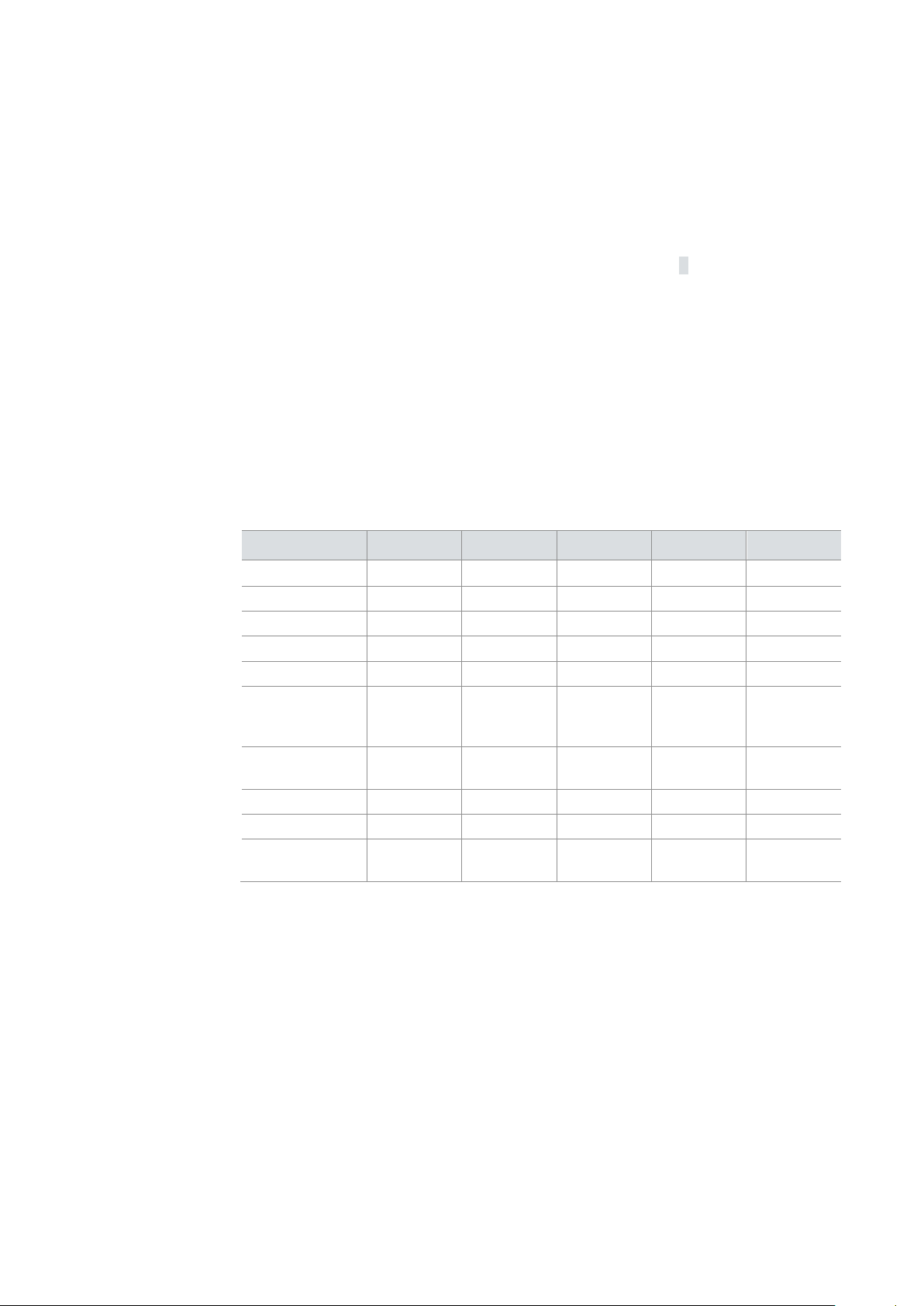
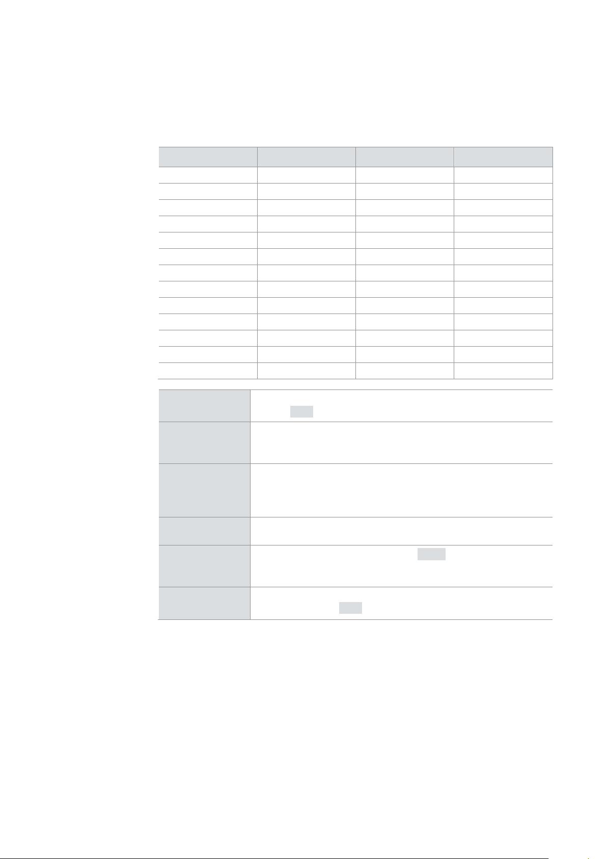
Basic functions
The following table shows the differences of the basic version of the logger variants.
• • •
•
• • • • •
FlexRay (2x)
•
•
•
•
• • •
•
• • • • •
• • • • •
•
• •
• • • • •
> Analog expansion card with 8 analog inputs
2.1 General Information
GL3000 The GL3000 is a data logger with USB and Ethernet interface which processes CAN
messages with either 11-bit or 29-bit identifiers, Remote Frames, LIN messages and
analog measurement values. The data is stored on a Compact Flash card. The
configuration of the logger is done with the Vector Logger Configurator or the G.i.N.
GL3100 The GL3100 includes all the functionality of the GL3000. In addition its housing
GL3200 The GL3200 only differs from the GL3100 in that the data is recorded on a solid-state
GL4000 The GL4000 includes all the functionality of the GL3000 and also supports FlexRay
recording. In addition its housing features four buttons for input and a display for
GL4200 The GL4200 only differs from the GL4000 in that the data is recorded on a solid-state
Options All loggers can be extended with the following options:
Functions GL3000 GL3100 GL3200 GL4000 GL4200
CAN (9x)
LIN (2x)
Display
Keys (4x)
Digital
input/output
(each 8)
Analog inputs
(6x)
USB Host
Ethernet
Memory media CF/USB
> Wireless LAN
> UMTS
•
memory
CF/USB
memory
SSD CF/USB
• •
SSD
memory
© Vector Informatik GmbH Version 2.4 - 8 -
Page 11

User Manual GL3000/GL4000 Series GL3000/GL4000 Series – Overview
> 1 Ethernet connector
> 1 port for WiFi antenna (with WiFi option only)
delivery).
2.2 Connectors
2.2.1 Overview
General information The loggers have the following connectors:
Front:
> 1 card drive for Compact Flash cards (for GL3000, GL3100 and GL4000 only)
> 1 slot for removable SSD (for GL3200 and GL4200 only)
> 1 USB host connector (reserved)
> 1 USB device connector
Plug set The scope of delivery includes a plug set (2 x 25-pin, 1 x 50-pin) of the Automotive
Back:
> 1 main connector: DSUB50 plug (male), e.g. for voltage supply, CAN, LIN,
FlexRay, internal analog inputs, RS232, KL15/Ignition
> 1 analog connector: DSUB25 plug (male), e.g. for analog inputs of the expansion
card, RS232
> 1 digital connector: DSUB25 plug (female) for digital inputs and outputs
> 2 Ethernet connectors
> 1 USB host connector for the connection of an USB memory medium
> 2 AUX sockets (Binder 5-pol, female) for LOGview (LCD Display) and VoCAN
(speech input/output)
> 1 event plug (Binder 5-pol, male) for switch box E2T2L
sector for the DSUB connections with contacts and hoods. For a secure holding the
hoods can be screwed or clipped.
For the reliable assembly of the contacts a crimp tool is needed, e.g. a crimp tool can
be purchased from the CONEC company (www.conec.com):
> Material: Crimp tool for D-SUB standard stamped and formed contacts
> Order number: 360 X 10079 X
Alternatively DSUB plugs with solder contacts can be used (not contained in scope of
© Vector Informatik GmbH Version 2.4 - 9 -
Page 12
User Manual GL3000/GL4000 Series GL3000/GL4000 Series – Overview
pin assignment
2.2.2 Main Plug
DSUB50
The pins of the main plug (DSUB50, male) have the following meaning:
Pin Assignment Pin Assignment
1 FlexRay1+ 26 CAN3 Vbatt
2 FlexRay1- 27 CAN3 GND
3 GNDSense 28 CAN4 GND
4 GND 29 CAN4 Vbatt
5 GND 30 LIN1 Vbatt
6 CAN1 High 31 LIN2 Vbatt
7 CAN1 Low 32 UART3 Tx
8 CAN2 High 33 UART3 Rx
9 CAN2 Low 34 FlexRay2+
10 CAN3 High 35 FlexRay2-
11 CAN3 Low 36 BattSense
12 CAN4 High 37 Battery (VCC)
13 CAN4 Low 38 Battery (VCC)
14 LIN 1 39 CAN5 High
15 LIN 2 40 CAN5 Low
16 KL15/Wake 41 CAN6 High
17 K-Line 42 CAN6 Low
18 AnaIn1 43 CAN7 High
19 AnaIn2 44 CAN7 Low
20 AnaIn3 45 CAN8 High
21 AnaIn4 46 CAN8 Low
22 CAN1 Vbatt 47 CAN9 High
23 CAN1 GND 48 CAN9 Low
24 CAN2 GND 49 UART2 Tx
25 CAN2 Vbatt 50 UART2 Rx
The two pins are connected to one another internally. They are
Battery
(Term. 30)
used to supply the logger with power. In case of increased current
consumption and/or a small cable diameter, we recommend
connecting both pins.
© Vector Informatik GmbH Version 2.4 - 10 -
GND
CAN
The two GND pins on the main plug and the GND pin on the
analog plug are connected to one another internally. In case of
increased current consumption and/or a small cable diameter, it is
recommended connecting both pins.
For CAN (see chapter 2.3.1), the CANx High and CANx Low pins
are connected. For the galvanically decoupled piggybacks, the
CANx GND and CANx Vbatt pins must also be connected.
Page 13

User Manual GL3000/GL4000 Series GL3000/GL4000 Series – Overview
ground (GND) pins of the two voltage supplies must be connected.
Then temporarily up to 1200 A can be discharged.
The LIN channels are supplied with maximum 12 V from the supply
voltage of the data logger. If the reference voltage for a LIN
channel is higher than 12 V, this voltage (e.g. 24 V) must be
LIN
applied to the LIN1_Vbatt or LIN2_Vbatt
the LIN1/2_Vbatt pins are not connected.
It is recommended to connect also GND as ground supply beside
the LIN pins.
pins. In all other cases,
FlexRay
Analog inputs
UART
KL15/Wake
BattSense,
GNDSense
Caution: It is recommended to connect the logger to the same voltage supply (e.g.
battery of the vehicle) as the vehicle or test equipment, respectively.
If two different voltage supplies are used for the logger and the test equipment, the
For FlexRay (see chapter 2.3.4), the FlexRay1+/FlexRay1- and
FlexRay2+/FlexRay2- pins are connected.
For analog inputs 1 - 4, the AnaInx pins are connected.
Analog inputs 5 and 6 are hard-wired internally and connected to
BattSense and KL15/Wake respectively. They are therefore not
accessible through a plug.
For the serial interfaces (see chapter 2.4.10), the UARTx Tx and
UARTx Rx pins are connected. The UART2 Tx/Rx pins are
connected internally with the UART2 Tx/Rx pins of the analog plug.
The logger is woken up by a positive edge on this pin.
KL15/Ignition, for example, can be connected for this purpose.
If the cables to the logger are long, the voltage drops off on the
Term. 30 line and the GND line due to the operating current. As a
result, a minimally lower voltage than the actual wiring system
voltage is measured with AnaIn5. To prevent this, the BattSense
and GNDSense pins can be connected close to the wiring system
voltage. AnaIn5 then measures the voltage at these pins.
Reverse-polarity
protection
For the voltage supply via Battery (Pins 37/38) and GND (Pins 4/5) a complete
reverse-polarity protection is available that in parallel also suppresses negative peaks
from the main power supply. A protection against positive peaks is also available.
Dependent on the temperature peaks from 35.88 V up to 42.12 V can be absorbed.
© Vector Informatik GmbH Version 2.4 - 11 -
Page 14
User Manual GL3000/GL4000 Series GL3000/GL4000 Series – Overview
pin assignment
2.2.3 Analog Plug
DSUB25
The pins of the analog plug (DSUB25, male) have the following meaning:
Pin Assignment Pin Assignment
1 AnaIn7+ 14 AnaIn7-
2 AnaIn8+ 15 AnaIn8-
3 AnaIn9+ 16 AnaIn9-
4 AnaIn10+ 17 AnaIn10-
5 AnaIn11+ 18 AnaIn11-
6 AnaIn12+ 19 AnaIn12-
7 AnaIn13+ 20 AnaIn13-
8 AnaIn14+ 21 AnaIn14-
9 Reserved 22 Reserved
10 5V (out) 23 UART2 Rx
11 UART2 Tx 24 Vbatt (out)
12 RS232LinuxRx 25 RS232LinuxTx
13 GND
Analog
expansion
The analog inputs (differential) of expansion card A8I (see
chapter 2.4.6) are connected using this plug.
This pin can be used as ground for 5V (out) and Vbatt (out). The
GND
5V (out)
Vbatt (out)
UART
RS232LinuxRx,
RS232LinuxTx
GND pin on the analog plug and the two GND pins on the main
plug are connected to one another internally.
Externally connected devices can be supplied with 5 V through
this pin. The voltage supply at this pin is switched off with a
switch if the logger is in sleep mode or standby mode. This
output can supply currents up to 1A.
This pin outputs the voltage active at pin Battery (VCC) and is
protected with 2A.
For the serial interface (see chapter 2.4.10), the UART2 Tx and
UART2 Rx pins are connected. These pins are connected
internally with the UART2 Tx/Rx pins of the main plug.
These pins support an access to the logger to set the real time
clock (see chapter 3.2.4).
© Vector Informatik GmbH Version 2.4 - 12 -
Page 15
User Manual GL3000/GL4000 Series GL3000/GL4000 Series – Overview
pin assignment
2.2.4 Digital Plug
DSUB25
The pins of this digital plug (DSUB25, female) have the following meaning:
Pin Assignment Pin Assignment
1 Reserved 14 DigIn1
2 DigOut1 15 DigIn2
3 DigOut2 16 DigIn3
4 DigOut3 17 DigIn4
5 DigOut4 18 DigIn5
6 DigOut5 19 DigIn6
7 DigOut6 20 DigIn7
8 DigOut7 21 DigIn8
9 DigOut8 22 Vbatt (out,switched)
10 Reserved 23 DigGND
11 Reserved 24 DigGND
12 Reserved 25 Sync (reserved)
13 Reserved
Digital inputs
The digital inputs (see chapter 2.4.4) are connected via the DigInx
pins.
Digital
outputs
DigGND
Vbatt (out,
switched)
The digital outputs (see chapter 2.4.5) are connected via the
DigOutx and DigGND pins.
The two DigGND pins are the common ground of the digital
outputs and connected to one another internally. They are used to
divert possible high currents that could flow in on digital output
DigOutx. They are bridged internally with GND via a fuse.
It is recommended connecting a good ground if digital outputs are
used with high currents.
For currents higher than 1 A, the ground DigGND (preferably both
pins 23 and 24) must be connected to the vehicle ground (GND at
main plug).
This pin outputs the voltage of Battery via a 1 A electrical fuse if
the logger is switched on.
This output is used for the operation of small accessory devices
which have no own sleep mode and are supposed to operate when
the logger is awake.
The ground of such device must be connected to the vehicle
ground (GND at main plug).
© Vector Informatik GmbH Version 2.4 - 13 -
Page 16

User Manual GL3000/GL4000 Series GL3000/GL4000 Series – Overview
Ethernet connections on the back with the following meanings:
> Eth 1: Configuration of the logger and reading out of the logging files
> Eth 3: Connector for GLA150 (accessory for MOST150).
described in Tutorial: Usage as interface.
with the following meanings:
> USB device connection with USB B socket for connection on the PC.
medium.
2.2.5 Ethernet Connections
Ethernet connector One 10/100 Mbit Ethernet connection is located on the front, and two 10/100 Mbit
Logger as bus
interface
Front
Back
> Eth 2: Configuration of the logger and reading out of the logging files (analog to
Eth1), connector for one camera (CAMlog2 or network camera HostCAM) and for
the usage as interface in CANoe/CANalyzer.
The loggers support a monitoring interface that allows the use of loggers as bus
interface for monitoring in CANoe/CANalyzer (since version 7.6 SP3).
The logger is connected via Ethernet to the CANoe/CANalyzer PC and sends after
measurement start the bus data to CANoe/CANalyzer, where the data can be
analyzed in the measurement setup. Sending messages with CANoe/CANalyzer is
not possible. The relevant CANoe/CANalyzer licenses must be provided by a
connected hardware interface on the PC or by a license dongle.
You can find further information in the Vector Logger Configurator manual, chapter
Monitoring Interface. There the configuration of the logger and CANoe/CANalyzer is
2.2.6 USB Connections
USB connection Two USB connections are located on the front, and one USB connection on the back
Front
> USB 1: Reserved.
Back
> USB 2: USB host connection with USB A socket for connection of a USB memory
© Vector Informatik GmbH Version 2.4 - 14 -
Page 17

User Manual GL3000/GL4000 Series GL3000/GL4000 Series – Overview
for the connection of the following logger accessories:
> VoCAN (for voice recording and output)
The plug pin assignment is as follows (view of the contacts of the logger socket):
used, CAN9 is fully available.
2.2.7 AUX Connections
AUX connection
The two additional 5-pin plug connections (connector series 711) AUX are intended
> LOGview (external display)
> Switch Box CAS1T3L (with one button, three LEDs and one sound)
> Switch Box CASM2T3L (with two buttons, three LEDs, one sound, and
microphone for voice recording)
Pin Assignment
1 +5V
2 Ground
3 CAN high
4 CAN low
5 Vbatt
The AUX connections are wired to CAN9 internally. For this reason, this channel is
always equipped with a high-speed transceiver without wake-up capability and can no
longer be used freely if an AUX connection is used. If the AUX connections are not
© Vector Informatik GmbH Version 2.4 - 15 -
Page 18

User Manual GL3000/GL4000 Series GL3000/GL4000 Series – Overview
freely programmable.
The plug pin assignment is as follows (view of the contacts of the logger plug):
The operating frequency of the antenna is approximately 2.4 GHz.
distances than this are not recommended.
2.2.8 Event Connection
Event connection This plug is used for the connection of the Switch Box E2T2L with two buttons and
two LEDs, which is included in the scope of delivery. The buttons and the LEDs are
Pin Assignment
1 GND
2 3.3V
3 A
4 B
5 T
Switch Box wiring
2.2.9 WiFi Connection
WiFi antenna
connection
Each logger delivered with the WiFi option has a connection for the WiFi antenna on
the back. In the case of a logger without the WiFi option, a plastic plug is located
there instead.
Caution: To satisfy FCC RF exposure requirements for mobile transmitting devices, a
separation distance of 20 cm or more should be maintained between the antenna of
this device and persons during operation. To ensure compliance, operations at closer
© Vector Informatik GmbH Version 2.4 - 16 -
Page 19

User Manual GL3000/GL4000 Series GL3000/GL4000 Series – Overview
CAN channels
The loggers support 9 CAN channels.
set via the configuration.
used in other loggers.
Available piggybacks for the GL3000/GL4000 series:
Piggyback 1055/1055mag as successor of Piggyback 1054/1054mag
piggybacks must be powered from a different source than the logger.
2.3 Bus Systems
2.3.1 CAN
Channel 1 - 4
Freely configurable via piggyback PCBs
Permanently occupied by high-speed CAN transceiver with
wake-up capability
Permanently occupied by high-speed CAN transceiver without
wake-up capability
Wake-up capability
Channel 5 - 8
Channel 9
The logger can be woken up on CAN channels 1 - 8. The wake-up capability can be
2.3.2 CAN Piggybacks
Piggybacks A piggyback is a plug-in PC-board which implements the interconnection of the logger
to a specific CAN bus by the use of various transceivers. The piggybacks are also
CAN Piggyback Transceiver Description Wake-up
Piggyback 10431 TJA1043 CAN high-speed Yes No
Piggyback 1043mag1 TJA1043 CAN high-speed Yes Yes
Piggyback 10422 TJA1042 CAN high-speed No No
Piggyback 1050 TJA1050 CAN high-speed No No
Piggyback 10553 TJA1055 CAN low-speed Yes No
Piggyback 1055mag3 TJA1055 CAN low-speed Yes Yes
Piggyback Single
Wire
Piggyback Truck
Trailer
1
Piggyback 1043/1043mag as successor of Piggyback 1041/1041mag
2
Piggyback 1042 as successor of Piggyback 251
3
TLE6255G CAN Single Wire Yes No
WABCO CAN
Truck&Trailer
Yes No
Galvanically
decoupled
Galvanically
decoupled
piggybacks
© Vector Informatik GmbH Version 2.4 - 17 -
Piggybacks 1041mag, 1043mag, 1054mag and 1055mag are magnetically decoupled
and available for CAN channels 1 - 4 of the GL3000/GL4000 series. Due to the
decoupling, the power supply and ground for these piggybacks must be connected at
the main plug (see chapter 2.2.2 Main Plug). For proper galvanic isolation, the
Page 20

User Manual GL3000/GL4000 Series GL3000/GL4000 Series – Overview
piggybacks
detected (“plug & play”).
sensitive lines in the unit.
series
and the flat ribbon cable. Under no circumstances may they be folded or crushed!
8. Please also attach the black decorative caps.
Info: For the galvanically decoupled transceiver, power supply (CAN1/2/3/4_Vbatt)
and ground (CAN1/2/3/4_GND) must be connected separately.
Replacing
GL3000/GL4000
The piggybacks can be exchanged. The installed piggybacks are automatically
Info:
> First read the installation instruction completely.
> The case has to be opened to exchange the piggybacks.
> This must be done very cautiously and carefully, in order to not damage the
Now proceed as follows:
1. Screw off the back cover (with the main plug) of the logger. First remove the black
decorative caps and then unscrew the crosshead screws.
2. Carefully remove the back cover with the board from the housing until the
piggybacks are accessible. It is sufficient to pull out the board halfway.
Note that the USB cable of the GL3200 and GL4200 may under no circumstances
be folded or pulled!
3. Looking from the main plug, the four slots are located at the edge of the board in
the order of CAN1 - CAN4. The locations are marked red in Figure 1.
4. Remove the piggyback carefully from the mounting location.
5. Insert the new piggyback. As the piggybacks are structured asymmetrically, it is
not possible to use them in a turned position. If some slots are not occupied, you
must ensure that each piggyback is inserted exactly in its intended slot on the (4 x
4 =) 16-pin measuring connection strip. Galvanically isolated piggybacks contain
four further pins.
6. Reassemble the unit in the reverse order. Place the main board back in the
housing and ensure that the board has been inserted into the correct guide rail
(piggybacks: groove 6, main board: groove 1).
Note the ribbon cable of the membrane keypad here (not in the case of GL3000)
7. It should be possible to slide the main board in the housing up to a few
millimeters from the end without forcing it in. Close the housing by applying light
pressure, and then secure it with the appropriate screw fasteners. The screws
should be secure but not excessively tight.
Caution: When performing this operation be sure not to touch the top or bottom of
the boards (logger main board or piggybacks).
© Vector Informatik GmbH Version 2.4 - 18 -
Page 21

User Manual GL3000/GL4000 Series GL3000/GL4000 Series – Overview
and is available as a logger accessory.
Therefore LIN piggybacks are not needed.
the LIN1/2_Vbatt pins are not connected.
set via the configuration.
Layout
GL3000/GL4000
series
Figure 1 – Layout GL3000/GL4000 series
2.3.3 LIN
LIN channels LIN frames can be recorded with both internal LIN channels. The sending of LIN
frames is not supported on these channels. A LINprobe X is required for this purpose
LIN transceiver The LIN transceivers are already mounted on the main board of the loggers.
LIN level The LIN channels are supplied with maximum 12 V from the supply voltage of the
data logger. If the reference voltage for a LIN channel is higher than 12 V, this voltage
(e.g. 24 V) must be applied to the LIN1_Vbatt or LIN2_Vbatt
Wake-up capability The logger can be woken up over either LIN channel. The wake-up capability can be
pins. In all other cases,
© Vector Informatik GmbH Version 2.4 - 19 -
Page 22

User Manual GL3000/GL4000 Series GL3000/GL4000 Series – Overview
FlexRay is also supported with these versions.
loggers.
Wake-up capability
The logger can be woken up on both FlexRay channels.
via Ethernet. With the GLA150 selectively the following MOST events can be logged:
> MOST Ethernet Frame Packet Events (MEP)
few occurred state changes the current state will be logged.
The configuration of the GLA150 is handled via the Vector Logger Configurator.
events
wake up.
Afterwards the GLA150 will be woken up by the logger.
other bus systems, e.g. CAN or LIN.
Connectors
At the GLA150 the following connectors are available:
2.3.4 FlexRay
FlexRay channels The loggers of GL4000 series also support FlexRay:
> 2 FlexRay channels A and B of a cluster for Rx/Tx, that means with XCP on
FlexRay or
> 2 FlexRay channels A independent for Rx only, that means without XCP on
FlexRay
The data is transmitted at 10 Mbit/s.
With the Vector Logger Configurator FlexRay databases in the XML format are
supported in versions FIBEX 2.0, FIBEX+, FIBEX 3.0 and FIBEX 3.1. XCP on
FlexRay transceiver The FlexRay transceivers TJA1080 are already mounted on the main board of the
2.3.5 MOST150
Overview For MOST150 the accessory GLA150 is available. It will be connected to the logger
Normally the status event is logged only at the occurrence of changes. Additionally it
Logging of MOST
After the logger switched to sleep mode, the GLA150 remains active and thereby
The time stamps of the MOST events are synchronized automatically with events of
> Status Events (bus state, system state, register, alloctable ...)
> Control Message Events
> MOST Data Packet Events (MDP)
can be configured that the status event is written automatically to the logging file
cyclically once per second. This ensures that also at a triggered logging with only a
The logging of the MOST events will start about 1 to 1.5 seconds after the logger’s
holds the MOST ring closed until the first time Light off will be detected at the input.
Connector Description
MOST150 Connection for fiber optic cable.
Network Connection for Ethernet cable. The cable is connected to
connector Eth 3 at the logger’s backside.
Power/Sync Connection for GLA150 connection cable. The cable is
connected to the logger’s analog plug, to supply the GLA150
with power.
© Vector Informatik GmbH Version 2.4 - 20 -
Page 23

User Manual GL3000/GL4000 Series GL3000/GL4000 Series – Overview
displayed:
> Ethernet cable
Switch on
The logger is switched on by applying the supply voltage.
logger immediately.
logging data in the RAM gets lost.
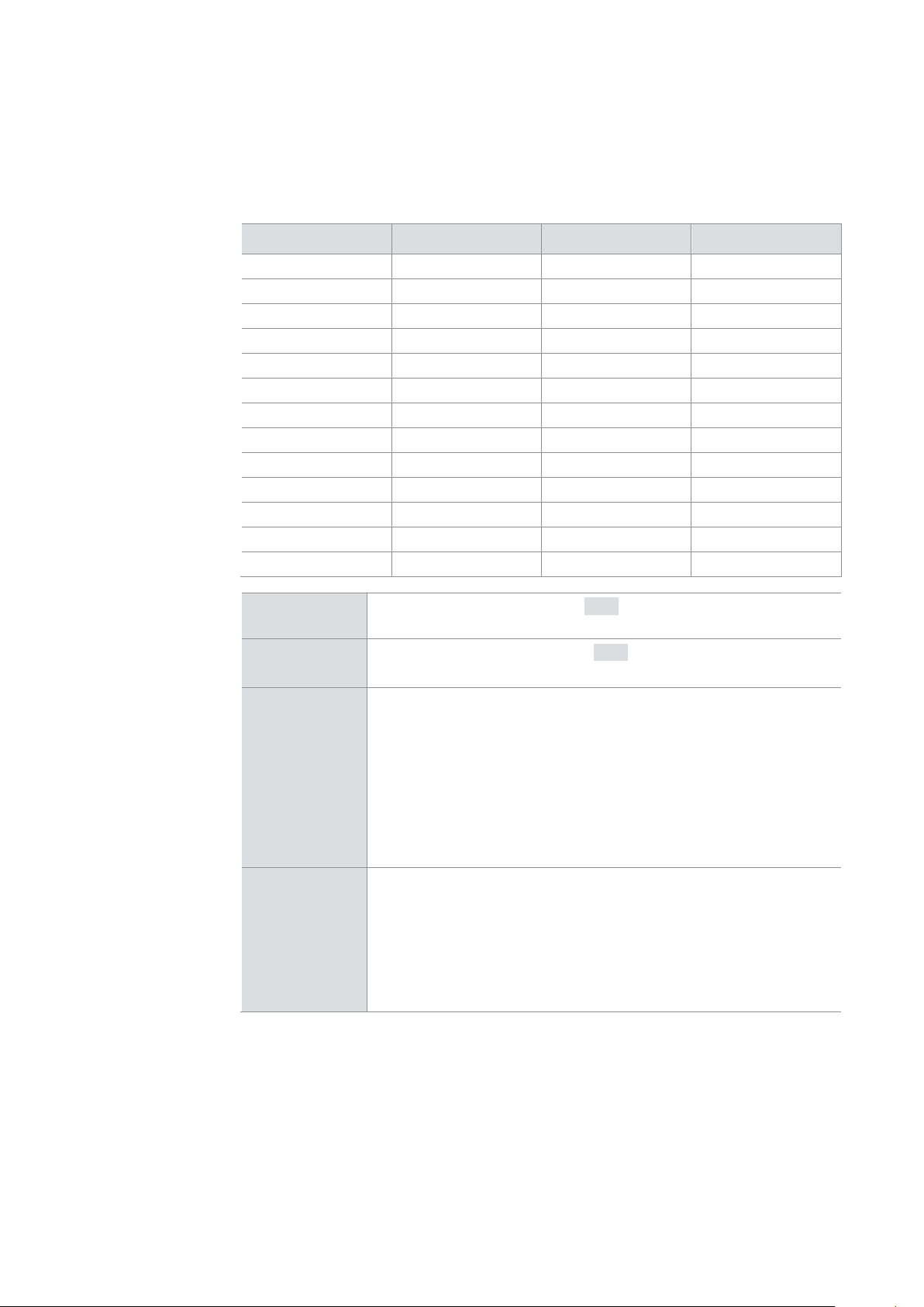
LEDs At the GLA150 six LEDs are available. With these LEDs the following states can be
Scope of delivery
LED Color Description
Power Green Device is running.
Communication Green Data connection to the logger is ready.
MOST Activity Yellow Ethernet packets, data packets or control
messages received.
Error Red Connection problem to the logger or data
overflow.
Info Red Reserved for future functionality.
MOST Lock Yellow Stable Lock
> GLA150
> GLA150 connection cable
> Fiber optic cable
2.4 Functions
2.4.1 Manual Switch On and Off the Logger
Manual switch off The logger is shut down and switched off by opening the front access panel. After
opening the front access panel the display shows first Stop Rec (end of recording).
After that the display shows Save XX% while saving the logging data from RAM to
memory media. When this procedure is finished, Shutdown is displayed while the
logger shuts down. During all the steps a running light from right to left is displayed by
the LEDs. If the running light and the display are off, the logger is shut down
completely.
The CF card can be removed after the LED color in the card slot changes from red to
green or the LED is off.
Depending on the configuration, bus activity after the shutdown can wake up the
The logger must not be switched off by disconnecting the voltage. By interrupting the
voltage supply, files are closed and the operating system shuts down properly. The
© Vector Informatik GmbH Version 2.4 - 21 -
Page 24

User Manual GL3000/GL4000 Series GL3000/GL4000 Series – Overview
night).
The sleep mode has a very low current consumption of typ. 1 mA.
After wake-up messages will be recorded after maximum 20 ms.
support the wake-up functionality on CAN (see section 2.3.2 CAN Piggybacks)
current consumption than the sleep mode.
Further recommendations on request.
cause mechanical damage!
2.4.2 Automatic Switch On and Off the Logger (Sleep / Wake-up / Standby)
Power Management For permanent use in vehicles the loggers are connected to the vehicle battery
permanently. Due to the sleep-/wake functionality the logger will be switched on and
off automatically by bus activity. This realizes an effective power management with
very quick start times without stressing the vehicle battery in idle times (e.g. during
Sleep The loggers can be configured to switch to sleep mode automatically if no CAN, LIN
or FlexRay message was received within a defined time. This time can be defined in
the configuration program (maximum 18,000 s = 5 hours).
Wake-up The loggers wake up from sleep mode or standby mode
> after reception of a CAN message
> after reception of a LIN message
> after reception of a FlexRay message (GL4000 series only)
> positive edge on the wake-up line (clamp 15)
> wake-up timer via real time clock
The logger has to be equipped with CAN transceivers with wake-up capability to
Fast wake-up from
standby mode
The fast wake-up from standby mode allows the recoding of the very first message
waking up the logger. However, with typ. 300 mA the standby mode has a higher
2.4.3 Memory Media
Compact Flash cards The GL3000, GL3100 and GL4000 support Compact Flash cards. It is recommended
to use Compact Flash cards with industrial grade:
> Xmore industrial 8 GB (XM-CF-8G0-XIE52D(F), XM-CF-8G0-XIE53D(F))
> Xmore industrial 16 GB (XM-CF-16G-XIE52D(F), XM-CF-16G-XIE53D(F))
> Xmore industrial 32 GB (XM-CF-32G-XIE53D(F))
Currently Compact Flash cards higher than 32 GB with industrial grade are not
available. The logger already supports CF cards with higher capacity. The capacity is
not limited.
Removing Compact
Flash card
The card holder is located behind the front flap. Unlock and open the flap. When the
logger is switched on, the Compact Flash card must not be removed until the LEDs in
the card slot are green or off. Now press the button next to the slot. The Compact
Flash card is ejected from its slot and can be removed.
If the LEDs are red or red/green, the card must not be removed!
Do not pull the Compact Flash card from the card holder forcefully, since this could
© Vector Informatik GmbH Version 2.4 - 22 -
Page 25

User Manual GL3000/GL4000 Series GL3000/GL4000 Series – Overview
The SSD is fixed on a cartridge. Both must be ordered from Vector.
time.
eSATAp adapter.
card) on an external USB memory medium (e.g. USB SSD, USB flash drive).
memory media
USB memory media!
off during this time.
use the USB flash drive the CF card has to be removed from the logger.
the logger shuts down and switches off.
Removable SSD The GL3200 and GL4200 supports a 64 GB or 512 GB removable SSD (2.5 inch
SATA Solid State Disk) which is available as accessory. The SSD can be removed
and read out very quickly on the PC with an external power over eSATA connection.
Changing SSD
Read out via SSD
USB memory media
Connect USB
If the logger restarts immediately e.g. due to active CAN channels the power supply
The slot for the SSD is located behind the front flap. Unlock and open the flap. While
the logger is switched on, the SSD must not be removed before the LEDs of the SSD
holder are green ore off.
While the LEDs are red or red/green, it is not allowed to remove the SSD as the
logger closes the log files and shuts down the operating system properly during this
For the read out via the SSD an eSATAp slot in the PC and the delivered eSATAp
connection cable are necessary. If no eSATAp slot is available, you can use an USB-
At GL3000/GL3100/GL4000 data can be stored instead to a Compact Flash card (CF
The connection is made via the USB host connection on the back panel.
Note: The memory medium must be inserted or removed while the logger is switched
off. Make sure that the logger has shut down properly (e.g. by opening the front
panel) before removing the USB-memory media. Do not switch off the logger by
disconnecting power! In contrast to CF cards, the voltage supply is not buffered for
can be disconnected during the first seconds after restart as the operating system is
loaded at this time. Alternatively the USB memory media can be removed during the
first approx. 10 seconds after start of the logger. The LED in many USB flash drives is
Automatic detection The logger automatically detects if a CF card is inserted into the logger or if an
external USB memory medium is connected. On start the logger searches for a
memory medium in the following order:
1. CF card
2. USB memory medium
As soon as a memory medium is found it is scanned for a new configuration. If a
configuration is found that is newer than the configuration on the logger an update will
be performed. Afterwards data will be logged on this memory medium.
If for example a CF card is inserted and at the same time an USB flash drive is
connected only the CF card will be used and the USB flash drive will be ignored. To
According to the logger type, a CF card or removable SSD must be available or a
USB memory medium must be connected. If a memory medium is missed some
beeps can be heard and loggers with integrated display show No Card. Afterwards
Info for formatting: The memory media have to be FAT32 formatted. For optimum
speed we recommend FAT32 formatting with the maximum cluster size of 64 Kbyte.
© Vector Informatik GmbH Version 2.4 - 23 -
Page 26

User Manual GL3000/GL4000 Series GL3000/GL4000 Series – Overview
input with GND the status is set to Low (FALSE).
Technical data
must be connected to the vehicle ground (GND at main plug).
Technical data
2.4.4 Digital Input
Digital input The loggers support eight digital inputs.
A digital input can be used e.g. as external trigger.
In unconnected state the digital inputs are set to High (TRUE). After connecting the
Voltage range
Pull-up resistance 100 kΩ
-0.8 V … 50 V
Sampling rate
Low level
High level
State unwired input
1 kHz
< 0.5 V
> 1.9 V
High (TRUE)
Input resistance > 200 kΩ
2.4.5 Digital Output
Digital output The loggers support eight digital outputs.
A digital output can be used to operate external hardware, for example. The voltage
applied to the digital output is wired to ground via an FET switch.
The two DigGND pins are connected to one another internally and are used to divert
possible high currents that could flow in on the digital output. They are bridged
internally to GND via a fuse.
For currents higher than 1 A, the ground DigGND (preferably both pins 23 and 24)
Voltage range
Nominal output current
(all channels on)
-0.3 V … 40 V
Typ. 500 mA for each output
Max. 1000 mA for each output
Current limitation
Input resistance
(On-resistance)
Amount of load current of
all channels
Circuit time
© Vector Informatik GmbH Version 2.4 - 24 -
Min. 1.0 A for each output
Typ. 1.5 A for each output
Max. 2.0 A for each output
0.8 Ω
Max. 4 A
Typ. 1 ms
Page 27

User Manual GL3000/GL4000 Series GL3000/GL4000 Series – Overview
connected to BattSense and KL15/Wake.
Technical data
logger, the measurement values of the first 80 ms are lost.
Technical data
2.4.6 Analog Inputs
Analog inputs The logger has six independent analog inputs which can be configured separately.
Input 1 - 4 are freely disposable. Inputs 5 and 6 are hard wired internally and
Input 1 - 4
Freely available
Analog expansion
card
Input 5
Input 6
Voltage range
Resolution
Precision
Sampling rate
Type
Connected with BattSense
Connected with KL15/Wake
0 V … 18 V
10 bit
1 %
Max. 1 kHz
Single-ended to ground
Input resistance 155.6 kΩ
Reverse-polarity protection
The logger can be expanded by eight independent analog inputs using a card. The
inputs are freely available as channels 7 through 14 and can be configured
separately. These channels are differential and provide higher resolution and better
precision than the internal analog inputs.
The extension cards are calibrated after production. The calibration data is stored on
the board, so that you can install or exchange the analog card later. For the
installation it is sufficient to plug in the extension card and to fix it with four screws.
After start the extension card needs 100 ms before data can be measured. The
loggers start considerably faster (20 ms after switching on). As the analog values and
the values from the digital inputs are latched together with the CAN data in the pre-
-50 V … +50 V
Input 7 - 14
Voltage range
Resolution
Precision
Sampling rate
Type
Reverse-polarity protection
© Vector Informatik GmbH Version 2.4 - 25 -
Freely available
0 V … 18 V
12 Bit (5 mV)
0.2 %
Max. 1 kHz for each channel
Differential, unipolar
-50 V … +50 V
Page 28

User Manual GL3000/GL4000 Series GL3000/GL4000 Series – Overview
states.
small letters, numbers, umlauts and some special characters can be displayed.
logger’s firmware that is shown in the display and by the LEDs.
Duration
2.4.7 LEDs, Display, Keys
LEDs The five logger LEDs are freely programmable. They can be used to display different
Display
The loggers (except GL3000) feature an eight-position alphanumeric display. The
display is freely programmable and can be used for the display of text. Capital and
In the following table you can find an overview about the information output from the
Display LEDs Description
Startup Off Start of the logger.
Record* Off*
FLASHING Running light
Off Off Between configurations update and re-start.
Stop Rec Off Configuration is stopped.
Save XX% Running light
Off All LEDs cyclical
blink 2 times in quick
succession.
No Card Off* No memory medium (CF card, SSD or USB
MediaErr — CF card/disk drive cannot be mounted resp.
USB Mode In the card reader
slot resp. cartridge:
red/green/red
Shutdown Running light
— Logger goes to Sleep mode
— Logger goes to Standby mode
*: The display and the LEDs can be overwritten by user-defined settings.
Execution of the configuration.
Update of the firmware, configuration, Linux
files etc.
FLASHING will be displayed several times and
the running light will be restarted.
: approx. 60 sec
Configuration is stopped. The data storage
progress is displayed (data > 100 KB).
Fault at logger CPU.
memory medium) available. Logger will switch
off afterwards.
plugged late.
USB cable is connected. Logger is in USB
mode.
Logger goes to Sleep/Standby mode or is
switched off.
Duration: approx. 1-2 sec
(display approx. 2 sec.)
(display approx. 2 sec.)
© Vector Informatik GmbH Version 2.4 - 26 -
Page 29

User Manual GL3000/GL4000 Series GL3000/GL4000 Series – Overview
configuration
the LEDs as follows:
configuration
update).
WiFi connection
Additional information on a WiFi connection:
Duration
Update firmware and
Please allow up to 5 minutes for extensive firmware updates (e.g. including Linux
The update is proceeded in several steps that are displayed on the display and via
Note: During the complete update the logger must not be disconnected from the
power supply.
> Start of the logger: Startup for approx. 1-2 sec
> Execution of the old configuration: Record and LEDs according to old
configuration for approx. 30 sec
> Update firmware and configuration: FLASHING with running light for approx. 60
sec, Display and LEDs could be off for 10-20 sec in the meantime
> Execution of the new configuration: Record and LEDs according to new
Display LEDs Description
Record* Off*
CONNECT Running light
CTimeXX
CStatXXX
LoadInit Off WiFi connection established.
Download Running light
Load:XX%
XXX KB/s
Running light
Running light
Establishment of the WiFi connection in
parallel to the execution of the configuration.
Establishment of the WiFi connection before
shutdown.
Configuration is stopped.
: max. 80 sec
Configuration is stopped.
Establishment of the WiFi connection with
display of the elapsed time in seconds and the
last error status.
Configuration is stopped.
WiFi data transfer of the logging files to the PC
is started.
During the WiFi data transfer alternately the
progress and the throughput is displayed.
RtUpdate Running light
CTimeout Running light
APreject Running light
Rejected/
byServer
© Vector Informatik GmbH Version 2.4 - 27 -
End of transfer:
Off
Running light
Transfer of a new configuration (*.COD) to the
logger.
Error: Communication Timeout
Error: The connection to the Access Point was
refused.
Error: MLserver refuses the connection, e.g.
the registration of the logger is missed.
Page 30
User Manual GL3000/GL4000 Series GL3000/GL4000 Series – Overview
panel. These buttons can be used as triggers, for example.
and LEDs are freely programmable. These buttons can also be used as triggers.
located on the back of the logger.
the operating system shut down properly should a power failure occur.
data.
pins of the CONSOLE cable are assigned as follows.
Event keys
Remote control
Display LEDs Description
NetFail Running light
*: The display and the LEDs can be overwritten by user-defined settings.
The loggers (except GL3000) feature four programmable event buttons on the front
All loggers include a remote control (Switch Box E2T2L) with two buttons (red and
black) and two LEDs (one red and one green) in the scope of delivery. The buttons
General communication error, e.g. a cable was
unplugged.
2.4.8 Beep
Beep The loggers have a speaker that acoustically alerts the user e.g. in case of a trigger.
Triggers and beep can be defined using the configuration program. The hole is
2.4.9 UPS
UPS For recording data on CF card or Solid State Disk the loggers contain an
uninterruptible power supply for up to two seconds so that the files may be closed and
2.4.10 Serial Interfaces
RS232 for logging
mode
RS232 for
configuration mode
For recording and transmitting data the serial interfaces (UART2 and UART3) of the
logger can be used. The baudrate of the interface can be set. Received data can be
stored as CAN messages.
The serial interfaces cannot be used to load a configuration or to read out logging
The loggers have an additional interface (RS232LinuxRx/Tx) that is not necessary in
the logging mode. During installation the network settings and the real time clock are
set in the configuration mode via this interface. You can find further information for
setting the real time clock in chapter 3.2.4 Quick Start.
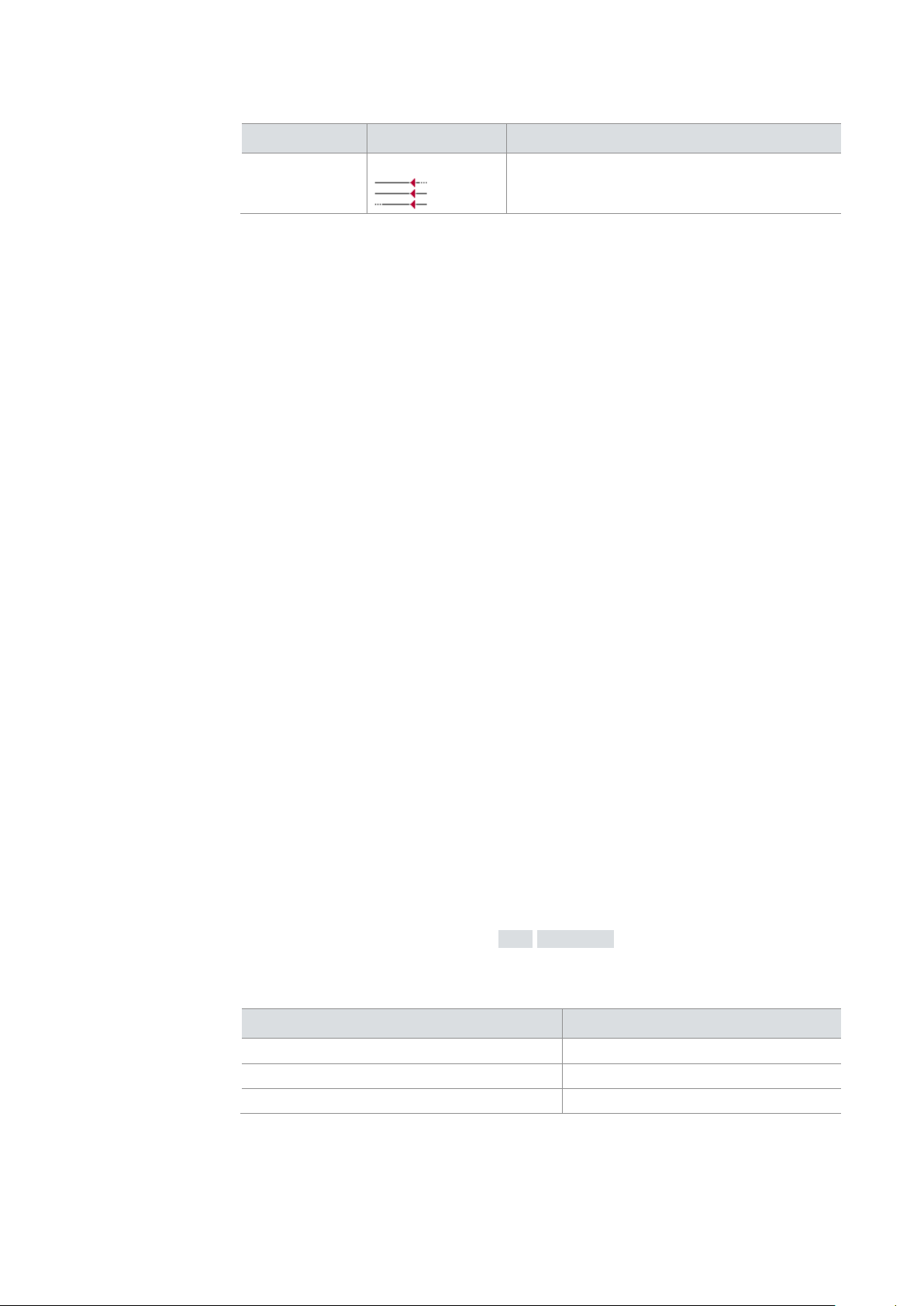
For the connection between logger and PC use the delivered CONSOLE cable. The
DSUB25 female (to analog plug) DSUB9 female (to PC)
RS232LinuxTx (Pin 12) 2
GND (Pin 13) 5
RS232LinuxRx (Pin 25) 3
© Vector Informatik GmbH Version 2.4 - 28 -
Page 31

User Manual GL3000/GL4000 Series GL3000/GL4000 Series – Overview
Quick Start).
T = -40 °C to +40 °C in the rest of the time
Replacing battery
The battery is exchanged as follows:
pull out the PCB halfway.
guide rail (piggybacks: groove 6, main board: groove 1).
2.4.11 Real-Time Clock with Battery
Real-time clock The loggers have an internal real-time clock, which is battery supplied, and thus
continues running even if the logger is disconnected from power supply. The real-time
clock inside the logger is required to store the date and time together with the logged
data.
It is recommended to set the real time clock before first logging (see chapter 3.2.4
Battery The Lithium battery has a typical durability of approximately 4 - 7 years under the
following conditions:
T = +40 °C to +70 °C for at most 40 hours per week
Figure 2 – Lithium battery
1. Screw off the back cover (with the main plug) of the logger. First remove the black
decorative caps and then unscrew the crosshead screws.
2. Carefully remove the back cover with the board from the housing. It is sufficient to
3. Remove the ribbon cable of the membrane keypad (not in the case of GL3000)
from the board by releasing the plug first. Remove also the flat ribbon cable from
the board (see Figure 1).
Note that these cables are connected with the front cover. Under no
circumstances may they be folded or crushed!
4. Now completely remove the board from the housing.
Note that the USB cable of the GL3200 and GL4200 may not get caught on the
slot of the SSD.
The battery is located in the front area of the board (see Figure 1).
5. Use wire-cutting pliers to cut off the connecting wires of the battery.
6. Now solder in the new battery and ensure correct polarity when doing so (see
Figure 1).
7. Reassemble the unit in the reverse order. Insert the main board halfway into the
housing and check to ensure that the board has been inserted into the correct
© Vector Informatik GmbH Version 2.4 - 29 -
Page 32

User Manual GL3000/GL4000 Series GL3000/GL4000 Series – Overview
the SSD housing that is fixed onto the inside wall of the housing.
Law in Germany).
available for connected USB memory media.
supply. The USB connection is not sufficient.
USB connection
If the logger is in logging mode, connect the logger with the PC as follows:
type B).
will switch off.
seconds.
8. Insert the ribbon cable of the membrane keypad with the wide wire oriented to the
middle of the board into the plug and lock it (not in the case of GL3000). Then
attach the flat ribbon cable to the board (see Figure 1). Pin 1 of the flat ribbon
cable is located on the outside.
Pay attention to the ribbon cable of the membrane keypad (not in the case of
GL3000). Under no circumstances may it be folded or crushed!
At the GL3200 and GL4200 you have to direct the USB cable along the board of
9. Now slide the main board completely into the housing. It should be possible to
slide the main board in the housing up to a few millimeters from the end without
forcing it in. Close the housing by applying light pressure, and then secure it with
the appropriate screw fasteners. The screws should be secure but not
excessively tight.
10. Please also attach the black decorative caps.
11. Dispose of the removed battery according to the applicable laws (e.g. the Battery
2.4.12 USB
USB Loggers with inserted CF card or SSD can be connected to the PC via USB for the
read out of logging data and for new configuration. Therefore the logger will be
switched to the USB mode. In Windows the logger is shown as an USB drive (similar
to USB hard disks). The Vector Logger Configurator identifies the logger as device
and displays additional information under Device Information. The USB mode is not
To switch into the USB mode, the logger must be connected to an external voltage
1. Check if the logger is already in logging mode. The display shows Record and
After opening the front access panel the logger will close the logging and will wait
the LEDs lit as configured.
2. First connect the USB cable to the PC (USB connector type A).
3. Open the front access panel.
4. Quickly connect the USB cable with the USB device connector (USB connector
minimum 6 seconds for the USB connection. If logging data are still written to the
memory medium the waiting time will be extended respectively. During this time the
display shows Stop Rec or Save XX% and the LEDs show a running light from the
right to the left. If the USB cable is not connected during this waiting time, the logger
If you connect the logger with USB, the logger switches to USB mode after about 30
© Vector Informatik GmbH Version 2.4 - 30 -
Page 33

User Manual GL3000/GL4000 Series GL3000/GL4000 Series – Overview
Compact Flash card behind the card, at the SSD on the front of the cartridge).
Do not remove the memory medium while the logger is in USB mode!
logging data can be read out and a new configuration can be written to the logger.
USB disconnection
Please proceed as follows to disconnect USB:
2. Disconnect the USB cable from the logger and close the front access panel.
logger awakes immediately.
are not supported.
logger.
You can find the MAC addresses on the label on the bottom of the logger.
USB mode If the USB cable is connected during this waiting time, the logger will switch to USB
mode and the display shows USB Mode. The LEDs still show the running light from
the right to the left, and on the memory medium green and red LEDs lit (at the
With the Vector Logger Configurator the Device Information can be displayed,
1. Disconnect the logger safely with the function Safely Remove Hardware of the
Windows task bar.
The logger will switch off. In case of remaining bus traffic on the CAN busses, the
2.4.13 Ethernet
Ethernet The loggers support the data transmission via Ethernet.
For data transmission a basic version of Multi-Logger ML Server software is included
in the scope of delivery. The software is described in the ML Server manual. The
software can be used to read out up to two loggers simultaneously. Safety protocols
The commercial Multi-Logger ML Server software supports the simultaneous reading
out of more than two loggers and the safety protocols listed in chapter 2.4.14.
The software also supports the filtering of MAC addresses. You can find them on the
label on the bottom of the logger.
For data transmission to ML Server the recording will be interrupted (LTL:
ConnectionRequest). If the recording should be continued during the transmission
(LTL: TransferRequest), the Online Data Transfer license must be installed on the
2.4.14 Wireless LAN
Overview The loggers support optional wireless LAN.
In the Vector Logger Configurator can be set, which events should trigger a WiFi
connection and which logged data should be transferred from the logger to the
destination system.
For data transmission to ML Server the recording will be interrupted (LTL:
ConnectionRequest). If the recording should be continued during the transmission
(LTL: TransferRequest), the Online Data Transfer license must be installed on the
logger.
Data transmission occurs as with Ethernet via the Multi-Logger ML Server software.
The basic version is included in the scope of delivery.
© Vector Informatik GmbH Version 2.4 - 31 -
Page 34

User Manual GL3000/GL4000 Series GL3000/GL4000 Series – Overview
Technical data
separately with a provider.
license also includes the Seed & Key support.
FAQ
Wireless LAN
IEEE 802.11g / 54 Mbit/s
Encoding algorithms
Security protocol (full
version of ML Server only)
WEP and WPA/WPA2
EAP/TLS, TKIP, RADIUS
2.4.15 3G
Overview The loggers optionally support wireless transmission via 3G.
The GLA320 modem is connected to the rear USB connection of the logger for this. It
is supplied by the logger via the USB connection.
The GLA320 is certified for the following regions:
> EU member states
> North America
> Japan and Malaysia
In the Vector Logger Configurator can be set, which events should trigger a 3G
connection and which logged data should be transferred from the logger to the
destination system.
Data transmission occurs as with WiFi via the Multi-Logger ML Server software. The
basic version is included in the scope of delivery.
The SIM card is not included in the scope of delivery. A contract must be entered
2.4.16 CCP/XCP
Overview The loggers support the recording of CCP/XCP data in DAQ and polling mode. The
A2L file is inserted directly in the Vector Logger Configurator and the signals to be
measured are selected.
For ECUs which are protected via Seed & Key procedure CANape is also required to
program the Seed & Key algorithm and create an SKB file containing this algorithm.
This SKB file is added to the logger configuration.
CCP/XCP is available as option. The license must be installed in the logger. The
Measurement mode DAQ (data aquisition) mode, polling mode
Supported CCP version
Supported XCP version
CCP 2.0 and CCP 2.1
XCP 1.0 and higher
(XCP on CAN, XCP on FlexRay)
© Vector Informatik GmbH Version 2.4 - 32 -
Page 35

User Manual GL3000/GL4000 Series GL3000/GL4000 Series – Overview
Overview
The loggers support the logging of diagnostic data via CAN bus.
analysis is supported in CANoe/CANalyzer.
FAQ
logger or the camera. Please note that the licenses cannot be transferred.
delayed. That may lead to a temporary impossibility to record any bus data.
Vector Logger Configurator V2.5 or higher
CANape for Seed & Key only
Configuration
Alternative:
CANape V8.0 or higher for DAQ mode, Seed & Key
CANape V13.0 or higher for polling mode
A2L file
Number of ECUs
Direct import in Vector Logger Configurator
Import in CANape
Multiple ECUs possible
still available
2.4.17 Diagnostics
The diagnostic descriptions (CDD, ODX, PDX, MDX) are read into the Vector Logger
Configurator. These files are necessary to set the communication parameters and to
select diagnostic service requests that would be sent on different events. The
CDD (CANdela diagnostic descriptions) up to V7.1
Diagnostic descriptions
Supported transport
protocol
Supported addressing
modes
ODX/PDX V2.0.1 and V2.2.0
MDX V3.0
ISO-TP
Normal
Normal fixed
Extended
Supported diagnostic
KWP2000, UDS
protocols
Seed & Key
Number of ECUs
Not supported
Several ECUs on different CAN buses possible
2.4.18 Camera HostCAM
Overview The loggers support the logging of color pictures via the network camera HostCAM.
The camera must be connected via the Eth2 Ethernet port on the back of the logger.
The GLX310 Ethernet switch is required for connection of a second HostCAM.
You can find further information on configuring and connecting the camera in the
HostCAM user manual.
For the logging of the color pictures a camera license must be installed either on the
Note:
> The simultaneous operation of more than two HostCAMs is not recommended
due to performance reasons.
> If multiple cameras are triggered simultaneously, it may result that during the
image transmission, the storage of recorded bus data to the memory medium is
© Vector Informatik GmbH Version 2.4 - 33 -
Page 36

User Manual GL3000/GL4000 Series GL3000/GL4000 Series – Overview
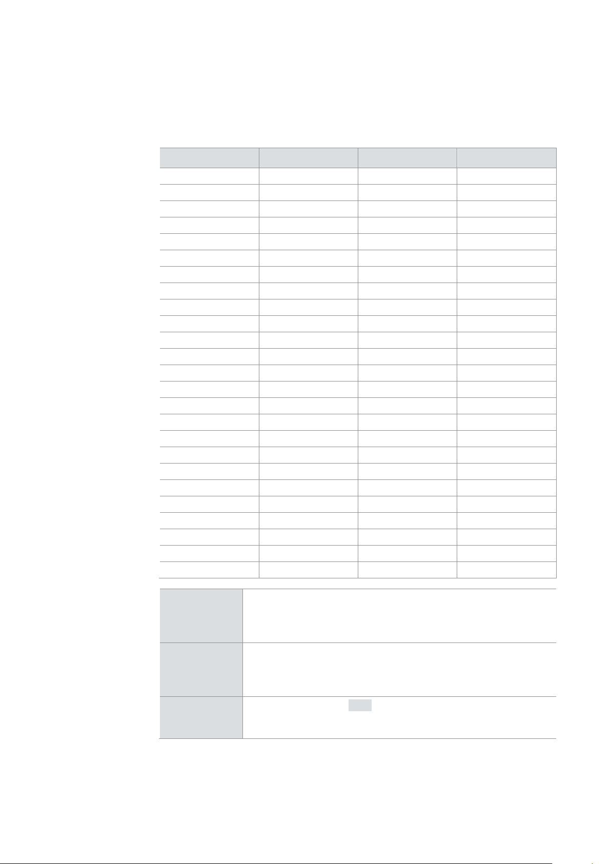
2.5 Technical Data
Channels1
Analog inputs
Analog expansion card
Digital inputs/outputs
USB
9 CAN channels
- CAN 1 - 4 via piggybacks
- CAN 5 - 8 fix via TJA1043
- CAN 9 fix via TJA1042
2 LIN channels fix viaTJA1021
2 FlexRay channels fix via TJA1080
(for GL4000 series only)
6 inputs (single-ended):
- Resolution 10 bit
- Precision 1%
- Sampling rate 1 kHz
- Voltage range 0 V…18 V
Optional:
8 inputs (differential)
- Resolution 12 bit
- Precision 0.2%
- Sampling rate 1 kHz
- Voltage range 0 V…18 V
8 inputs
8 outputs
2.0
Ethernet
Wireless LAN
UMTS/3G
Start-up time
Power consumption
Current consumption
Temperature range
Power supply
Dimensions (WxHxL)
3 10/100 Mbit/s interfaces
Optional:
WiFi card with WEP and WPA/WPA2
IEEE 802.11g / 54 Mbit/s
Different encoding algorithms
Optional
Max. 20 ms (without Fast Wake-up)
Recording the first message with Fast Wake-up
Typ. 8.5 W (without SSD)
Typ. 10 W (with SSD)
Operation: typ. 700 mA (without SSD)
typ. 800 mA (with SSD)
Start: typ. 1100 mA
Sleep mode: typ. 1 mA (without Fast Wake-up)
Standby mode: typ. 300 mA (with Fast Wake-up)
All data in each case with 12V.
-40 °C…+70 °C
(restricted with WiFi and 3G)
6 V…36 V (reverse-polarity protected), typ. 12 V
Approx. 213 mm x 78 mm x 235 mm
Housing
Battery
1
Serial number before x00500: CAN5 - 8: TJA1041A, CAN9: PCA82C251, LIN: TJA1020.
© Vector Informatik GmbH Version 2.4 - 34 -
Aluminium housing: Alubos 2070
Lithium battery, CR 2/3 AA type
Page 37

User Manual GL3000/GL4000 Series GL3000/GL4000 Series – Overview
> eSATAp connection cable (GL3200 and GL4200 only)
> “Industrial grade” CF cards in different capacities.
> VX1060 for read-out of ECU-internal signals via XCP on Ethernet
2.6 Included with Delivery
Standard scope of
delivery
Optional
> GL3000 or GL3100 or GL3200 or GL4000 or GL4200 logger
> Vector Logger Configurator on CD
> Vector Logging Exporter on CD
> G.i.N. Configuration Program on CD
> Base version of Multi-Logger ML Server software
> Manuals on CD
> Plug set 2 x 25-pin and 1 x 50-pin with contacts and hoods from the Automotive
sector
> Switch Box E2T2L (2 pushbuttons, 2 LEDs)
> USB cable
> CONSOLE cable
> CCP/XCP license for CAN and FlexRay
> Online Data Transfer License for data transmission to ML Server via Ethernet
> License for HostCAM (logger-based or camera-based)
> Analog expansion A8I
> WiFi, glass mount antenna with 3 m connection cables inclusive
> SSD with cartridge (GL3200 and GL4200 only). Must be ordered from Vector.
2.7 Accessories
Optional
> GLA320 modem (incl. antennas) for wireless data transfer via 3G
> CANgps/CANgps 5 Hz for recording the vehicle position via GPS
> LINprobe as extension of the LIN channels
> GLA150 for recording MOST150 data
> HostCAM for recording von color pictures
> VoCAN for voice recording and voice output (1 button, 4 LEDs and signal tone)
> CASM2T3L for voice recording (2 buttons, 3 LEDs and signal tone)
> CAS1T3L (1 button, 3 LEDs and signal tone)
> LOGview for displaying signal and status information
© Vector Informatik GmbH Version 2.4 - 35 -
Page 38

Page 39

User Manual GL3000/GL4000 Series Installation Configuration Programs
3 Installation Configuration Programs
In this chapter you find the following information:
3.1 Overview page 38
3.2 Installation Vector Logger Configurator page 38
Requirements
Setup
Overview
Quick Start
3.3 Installation G.i.N. Configuration Program page 42
Requirements
Setup
Overview
Quick Start
© Vector Informatik GmbH Version 2.4 - 37 -
Page 40

User Manual GL3000/GL4000 Series Installation Configuration Programs
The programs are included with delivery.
used in the G.i.N. Configuration Program.
configurations in LTL.
> This user manual
Restriction Windows 8.1: AUTOSAR databases are not supported.
1. Execute the setup, which is found on the installation CD: .\VLConfig\Setup.exe
3.1 Overview
Overview This instruction describes the installation of the software package for the
GL3000/GL4000 series containing:
> Vector Logger Configurator
Graphic user interface for easy configuration
> G.i.N configuration program
User interface to create complex configurations with LTL (Log Task Language)
Vector Logger
Configurator
G.i.N. Configuration
Program
The Vector Logger Configurator offers a wide range of features to easily create
configurations for the logger. The Vector Logger Configurator also supports the
download of the configuration and the upload of logging data including the export to
different file formats. Additionally the configuration can be saved as LTL code to be
The G.i.N. Configuration Program can be used as configuration program for high end
configurations. It offers full support of all features available with LTL (Log Task
Language). This program can be used to import LTL code from the Vector Logger
Configurator or from existing configurations written in LTL or to write own
3.2 Installation Vector Logger Configurator
Overview This instruction describes the installation of the Vector Logger Configurator for the
loggers containing:
> Vector Logger Configurator
> Online help for the Logger Configurator
> User manual for the Logger Configurator
3.2.1 Requirements
Operating system The following software requirements must be fulfilled to run the Vector Logger
Configurator:
> Windows 7 / Windows 8.1 (32/64 Bit)
> Windows 10 (64 Bit)
3.2.2 Setup
The Vector Logger Configurator is installed as follows.
© Vector Informatik GmbH Version 2.4 - 38 -
Page 41

User Manual GL3000/GL4000 Series Installation Configuration Programs
found on the installation CD under .\GLtools\setup.exe.
databases.
> CCP/XCP (optional)
2. Please, follow the instructions in the setup program to complete the installation.
3. After successful installation, the Vector Logger Configurator can be found in the
start menu (if selected during installation).
4. Also install the basic software e.g. for wireless transmission. The software can be
3.2.3 Overview
About Vector Logger
Configurator
Main features are:
Vector Logger Configurator enables the configuration of the loggers and offers a wide
range of settings. You may set baud rates for CAN and LIN, define triggers and filters,
set LEDs and manage logging files on the SD card. Furthermore for the CAN bus
diagnostics and CCP/XCP can be configured. For CCP/XCP the logger needs an
installed license. For Seed & Key CANape is required. Vector Logger Configurator
also supports trigger and filter access by symbolic names defined in CAN and LIN
> Customizable filters for CAN and LIN messages and FlexRay frames/PDUs
> Customizable triggers
> Support of CAN databases (DBC) and LIN databases (LDF)
> Support of FlexRay databases (FIBEX 2.0, FIBEX+, FIBEX 3.0 and FIBEX 3.1
each with XCP)
> Diagnostic support
> File management
© Vector Informatik GmbH Version 2.4 - 39 -
Page 42

User Manual GL3000/GL4000 Series Installation Configuration Programs
be opened via the Vector Logger Configurator program group in the start menu.
SSD is performed accordingly.
<Destination folder>/< Destination
subdirectory>.
Cross reference: The Vector Logger Configurator is described in detail in the user
manual of this configuration program. The user manual is available as PDF and can
3.2.4 Quick Start
Quick start Follow the instructions below to configure the logger with a Compact Flash card, start
long-term logging and read out logging data. Configuration and reading out with a
1. Start the program.
2. Open a new configuration via the menu File|New Project…. Select in the
displayed dialog the logger type.
3. Select suitable baud rates for CAN and/or LIN (Hardware|CAN Channels and/or
Hardware|LIN Channels), respectively.
4. Select the timeout to sleep mode (value > 0) in Hardware|Settings.
5. Insert an empty Compact Flash card into the card reader connected to the PC.
6. Save the configuration on the CF card via menu Configuration|Write to Memory
Card….
7. Open the front flap of the logger, insert the Compact Flash card into the logger
and then close the front flap again.
8. Connect the logger e.g. to your test system (CAN bus). Switch power on via
connecting cable on DSUB50.
9. Start logging. LED1 flashes permanently (standard setting for new configurations,
can be configured).
10. Stop logging by switching off CAN. Wait until the logger goes to sleep mode (CAN
transceiver with wake-up capability necessary) i.e. LED1 must be off.
11. Remove the card from the logger. Insert the Compact Flash card into the card
reader connected to the PC.
12. Open the File Manager node in the tree view.
13. Click on Card Reader|Classic View and make with <F5> a display refresh.
Select in Data source the drive of the CF card. Now all files on the card are
displayed.
14. Select in the General Settings the destination folder and the format for the
converted files
15. Select in the Advanced Settings the options for conversion.
16. Click on [Convert] to start the readout and conversion of all logging data. The
converted log file will be located in
© Vector Informatik GmbH Version 2.4 - 40 -
Page 43

User Manual GL3000/GL4000 Series Installation Configuration Programs
clock
Before delivery the loggers are set to CET.
procedure.
configuration on the logger that ensures that the logger is permanently awake.
7. With [Set] a connection to the logger is built up and the selected time will be set.
and time of the logger is continuously displayed.
Set the real-time
3. Start the Vector Logger Configurator. Make sure a configuration for GL3000
The following example describes how to set the date and the time of the logger.
1. Connect the logger via a CONSOLE cable on the analog plug (see chapter 2.4.10
Serial Interfaces) to the serial interface of the PC.
2. Start the logger (if it is not switched on yet) by supplying power via the connection
cable on the DSUB50. The logger must be switched on during the whole
Info: If the logger is configured to go to sleep mode while bus silence, you have
to ensure that it stays awake as long as there is activity on the bus, or load a new
series or GL4000 series is active.
4. Select in the menu item Device|Set Real-Time Clock….
5. In the Connection setting select the COM port to which the logger is connected.
6. In the Clock setting select
> PC to select the current PC time or
> Manual to enter a different time manually.
Info: After the start of the logger it takes approximately 15 seconds until the
setting of the real-time clock is possible.
To read the current time from the logger, select Logger from the Clock setting. Date
© Vector Informatik GmbH Version 2.4 - 41 -
Page 44

User Manual GL3000/GL4000 Series Installation Configuration Programs
> G.i.N. user manuals for the configuration program and the hardware
Windows 7, Windows 8.1 und Windows 10
be found on the installation CD under .\GLtools\setup.exe.
names defined in databases.
3.3 Installation G.i.N. Configuration Program
Overview This instruction describes the installation of the G.i.N. Configuration Program for the
loggers containing:
> G.i.N. Configuration Program
> Multi-Logger ML Server basic software
3.3.1 Requirements
Operating system The following software requirements must be fulfilled to run the G.i.N. Configuration
Program:
3.3.2 Setup
3.3.3 Overview
About G.i.N.
Configuration
Program
Follow the instructions below to install the G.i.N. Configuration Program:
1. Execute the setup, which is found on the installation CD:
.\GiNconf\setup.exe
Please, follow the instructions found there to complete the installation.
2. After successfully installation, the G.i.N. Configuration Program can be found in
the start menu.
3. If you want to use WiFi or 3G, you also have to install the basic software that can
The G.i.N. Configuration Program enables the configuration of the loggers and offers
a wide range of settings via LTL (Log Task Language). You may set baud rates for
CAN and LIN, define triggers and filters for CAN, LIN and FlexRay, set LEDs and
manage logging files on the Compact Flash card. CCP/XCP on CAN and XCP on
FlexRay can also be configured with the means of CANape, if the license is installed.
G.i.N. Configuration Program also supports trigger and filter access by symbolic
© Vector Informatik GmbH Version 2.4 - 42 -
Page 45

User Manual GL3000/GL4000 Series Installation Configuration Programs
> CCP/XCP (optional)
after installation of the program and can be called by the Help menu.
Main features are:
> Customizable filters for CAN, LIN and FlexRay messages
> Customizable complex triggers
> Support of CAN databases (DBC) and LIN databases (LDF)
> Support of FlexRay databases (FIBEX 2.0, FIBEX+. FIBEX 3.0)
> File management
Cross reference: The G.i.N. Configuration Program is described in detail in the LTL
user manual of the configuration program. The LTL user manual is available as PDF
© Vector Informatik GmbH Version 2.4 - 43 -
Page 46

User Manual GL3000/GL4000 Series Installation Configuration Programs
logging and readout logging data. Configuration with a SSD is performed accordingly.
inputting the device serial number and the vehicle name.
3.3.4 Quick Start
Quick start Follow the instructions below to configure the logger with a Compact Flash card, start
1. Start the program.
2. Create a new project (File|New Project). Select the project path and the device
GL3000 or GL4000/GL4200.
3. Create a new source file (File|New File) and insert the following source code:
SYSTEM
Can5Timing = Timing500K
ExternalStorage = On
SleepSeconds = 15
OUTPUT
LED1 = (_10msec > 50)
LED2 = (Second = 59)
STOP 1 (Second = 59)
START 1 (Second = 0)
END
Description of the configuration:
The baud rate on CAN5 is 500 kbaud. LED1 flashes continuously after switch-on,
and LED2 illuminates briefly every 60 seconds. A trigger is initiated every 60
seconds.
4. Save the file (File|Save File as) as LTL file in your project directory.
5. Compile this file via Project|Compile or press [F9]. A COD file is created.
6. Insert an empty Compact Flash card into the card reader connected to the PC.
7. Create a new folder with the name Configure in the root directory of the compact
flash card.
8. Copy the COD file created in this folder.
9. Remove the Compact Flash card from the card reader.
10. Open the front flap, insert the Compact Flash card into the logger and then close
the front flap again.
11. Connect CAN5 of the logger to a functional CAN bus and switch the logger on.
The device must be connected to a power supply here. Wait a few minutes to
record several logging files. When data is being recorded, LED2 illuminates once
a minute.
12. End recording by disconnecting the CAN bus. Wait until the logger is in sleep
mode. LED2 no longer illuminates.
13. Remove the card from the GL3000 resp. GL4000.
14. Insert the Compact Flash card into the card reader connected to the PC.
15. Start the Multi Logger Server Options program and enter the vehicle by
© Vector Informatik GmbH Version 2.4 - 44 -
Page 47

User Manual GL3000/GL4000 Series Installation Configuration Programs
output format.
16. Start the Multi Logger CardReader program.
17. Select the drive of the card reader and press the [Read] button.
A folder with the name of the vehicle is created in the global data directory
…\GiN\<ML>\data for the vehicle created. The following subfolders are created
in this folder:
> Configure
New configurations, i.e. COD files generated using the G.i.N. Configuration
Program, can be stored in this folder.
> Log
Each time data is read out, a new data record is stored in a subfolder in this
folder. The name of a subfolder is comprised of the date and time of the readout. This folder contains the read-out logging file (CLF) and the subsequently
exported ASC files.
To create additional output formats, add the read CLF file to the project as
follows:
> Select the shortcut menu item Add GiN logger lo gfiles under GiN logger
log files on the left-hand side of the window.
> Start the export program by double-clicking the CLF file and selecting the
© Vector Informatik GmbH Version 2.4 - 45 -
Page 48

Page 49

User Manual GL3000/GL4000 Series Index
4 Index
3
3G ....................................................................... 32
A
Analog inputs ...................................................... 25
Analog plug ......................................................... 12
AUX connection .................................................. 15
B
Battery................................................................. 29
Beep.................................................................... 28
C
CAN .................................................................... 17
CCP/XCP ............................................................ 32
Connectors ........................................................... 9
D
Delivery ............................................................... 35
G
G.i.N. Configuration Program ............................ 42
GLA150 .............................................................. 20
H
HostCAM ............................................................ 33
K
Key ..................................................................... 26
L
Layout GL3000/GL4000 .................................... 19
LED .................................................................... 26
LIN...................................................................... 19
M
Main plug ........................................................... 10
Memory media ................................................... 22
MOST150 ........................................................... 20
Diagnostics ......................................................... 33
Digital input/output .............................................. 24
Digital output ....................................................... 24
Digital plug .......................................................... 13
Display ................................................................ 26
DSUB25 ..................................................10, 12, 13
E
Ethernet .............................................................. 31
Ethernet connection ............................................ 14
Event connection ................................................ 16
F
Fast W ake-up ................................................. 7, 22
FAT32 ................................................................. 23
Features ................................................................ 9
FlexRay ............................................................... 20
Formatting ........................................................... 23
P
Piggybacks ......................................................... 17
Pin assignment .................................................. 10
Q
Quick start .................................................... 40, 44
R
Real-time clock .................................................. 29
Requirements ............................................... 38, 42
S
Serial interface ................................................... 28
Sleep .............................................................. 7, 22
Standby .......................................................... 7, 22
Support ................................................................ 5
T
Technical Data ................................................... 34
© Vector Informatik GmbH Version 2.4 - 47 -
Page 50

User Manual GL3000/GL4000 Series Index
Transceiver ......................................................... 17
U
UPS ..................................................................... 28
USB ..................................................................... 30
USB connection .................................................. 14
V
Vector Logger Configurator ............................... 38
W
Wake-up ......................................................... 7, 22
WiFi .................................................................... 31
WiFi connection ................................................. 16
© Vector Informatik GmbH Version 2.4 - 48 -
Page 51

Page 52

More Information
> News
> Products
> Demo Software
> Support
> Training Classes
> Addresses
www.vector.com
 Loading...