

Page 1
User Manual
GL1020FTE Avionic Logger
Version
English
1.5
Page 2

Imprint
Vector Informatik GmbH
Ingersheimer Str
D
Vector reserves the right to modify any information and/or data in this user documentation without notice. This documentation nor any of
its parts may be reproduced in any form or by any means without the prior written consent of Vector. To the
under law, all technical data, texts, graphics, images and their design are protected by copyright law, various international
other applicable law. Any unauthorized use may violate copyright and other applicable laws o
©
All rights reserved.
80
. 24
-70499 Stuttgart
maximum extent permitted
Copyright 2017, Vector Informatik GmbH. Printed in Germany.
444
r regulations.
treaties and
Page 3

User Manual GL1020FTE Avionic Logger Table of Contents
Table of Contents
1 Introduction 3
1.1 About this User Manual 4
1.1.1 Certification 5
1.1.2 Warranty 5
1.1.3 Support 5
1.1.4 Trademarks 5
2 GL1020FTE Avionic Logger 7
2.1 General Information 8
3 Start-Up/Commissioning 11
3.1 Hardware Preparation 12
3.1.1 Overview Connectors 12
3.1.2 DSUB25 Pin Assignment 13
3.1.3 Connection Cable 15
3.1.4 Mounting Plate 15
3.2 Software Preparation 16
3.2.1 Overview Configurator Program 16
3.2.2 Installation Vector Logger Configurator 16
3.3 Quick Start 17
3.4 Evaluation Notes 19
4 Functions 21
4.1 Operating Modes 22
4.2 Wake-up / Sleep 22
4.3 LED Display 22
4.4 Analog Inputs 23
4.5 Beep 24
4.6 Storage Media 24
4.7 Real-Time Clock with Battery 24
4.8 Lightning and Overvoltage Protection 24
4.9 Technical Data 26
4.10 Included with Delivery 26
5 Index 27
© Vector Informatik GmbH Version 1.5 - I -
Page 4

Page 5

User Manual GL1020FTE Avionic Logger Introduction
1 Introduction
In this chapter you find the following information:
1.1 About this User Manual page 4
Certification
Warranty
Support
Trademarks
© Vector Informatik GmbH Version 1.5 - 3 -
Page 6
User Manual GL1020FTE Avionic Logger Introduction
The user manual provides you the following access helps:
> At the end of the user manual you will find an index.
regarding utilized spellings and symbols.
File
Save
Source code
Here you can find additional information.
Step-by-step instructions provide assistance at these points.
Instructions on editing files are found at these points.
1.1 About this User Manual
To find information
quickly
> At the beginning of each chapter you will find a summary of the contents,
> In the header you can see the current chapter and section,
> In the footer you can see to which version the user manual replies,
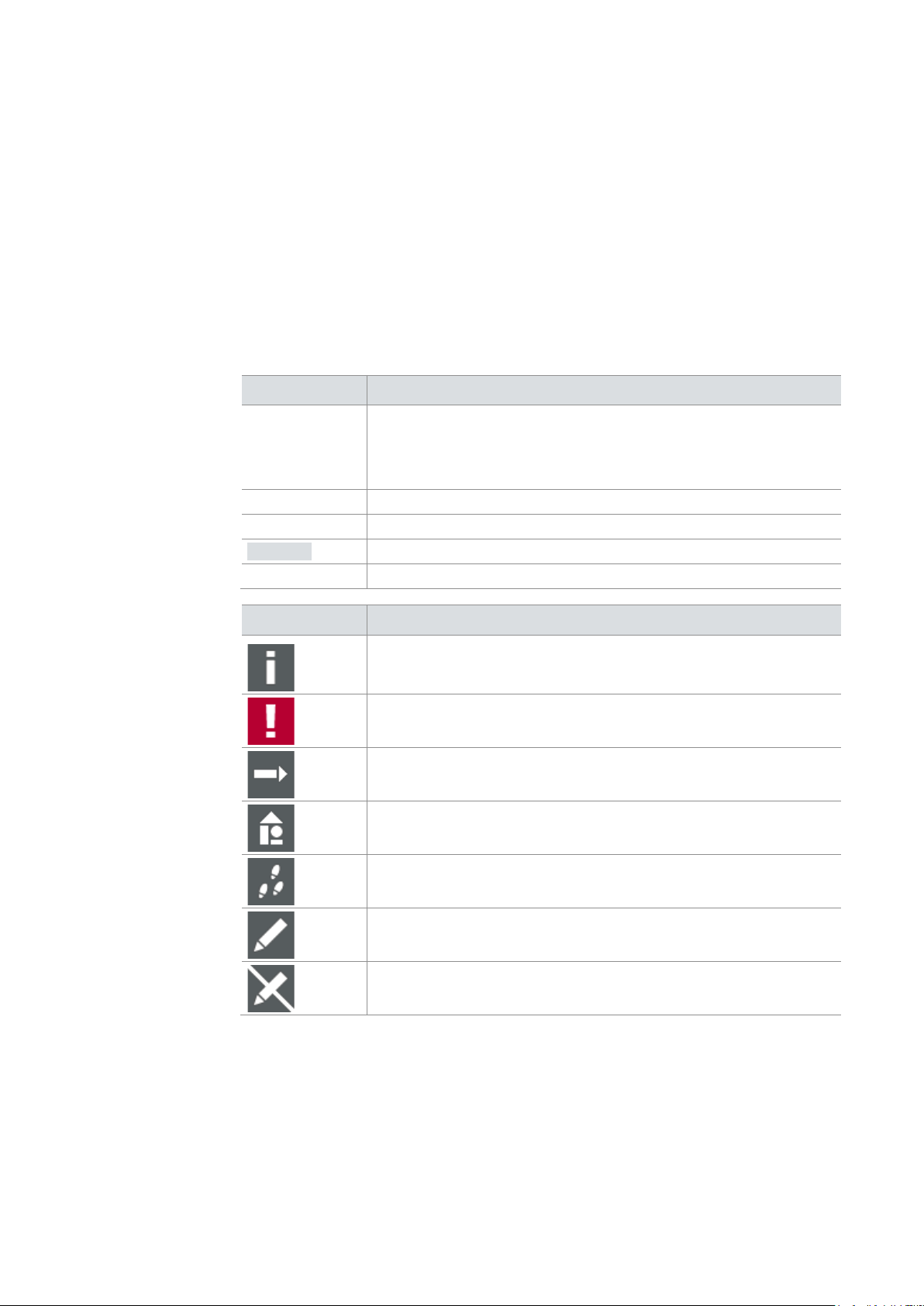
Conventions
In the two following charts you will find the conventions used in the user manual
Style Utilization
bold
Windows Legally protected proper names and side notes.
Hyperlink Hyperlinks and references.
<STRG>+<S> Notation for shortcuts.
Blocks, surface elements, window- and dialog names of the
software. Accentuation of warnings and advices.
[OK] Push buttons in brackets
|
File name and source code.
Notation for menus and menu entries
Symbol Utilization
Here you can find additional information and hints that eases the
work with the GL1020FTE.
This symbol calls your attention to warnings.
Here is an example that has been prepared for you.
This symbol warns you not to edit the specified file.
© Vector Informatik GmbH Version 1.5 - 4 -
Page 7

User Manual GL1020FTE Avionic Logger Introduction
Management System
The ISO standard is a globally recognized standard.
the contents and for damages which may result from the use of this documentation.
or you write an email to support@vector.com.
trademarks
trademarks of their respective owners.
1.1.1 Certification
Certified Quality
Vector Informatik GmbH has ISO 9001:2008 certification.
1.1.2 Warranty
Restriction of
warranty
We reserve the right to modify the contents of the documentation or the software
without notice. Vector disclaims all liabilities for the completeness or correctness of
1.1.3 Support
You need support? You can get through to our hotline at the phone number
+49 711 80670-200
1.1.4 Trademarks
Protected
All brand names in this documentation are either registered or non registered
© Vector Informatik GmbH Version 1.5 - 5 -
Page 8

Page 9

User Manual GL1020FTE Avionic Logger GL1020FTE Avionic Logger
2 GL1020FTE Avionic Logger
In this chapter you find the following information:
2.1 General Information page 8
© Vector Informatik GmbH Version 1.5 - 7 -
Page 10

User Manual GL1020FTE Avionic Logger GL1020FTE Avionic Logger
> Protection from indirect lightning effects and other environmental conditions.
Configurator.
> operational vibration
2.1 General Information
GL1020FTE The data logger GL1020FTE is flight test equipment dedicated to record avionic CAN
bus communication. It is designed for:
> Application in the pressurized fuselage area
> Fulfilling the typical requirements of aircraft EMI
The GL1020FTE is a data logger with USB interface which records messages and
analog values on the inserted SD card. This SD card is located in the housing and is
not accessible from the outside. The logger can be configured with the Vector Logger
Configurator. The installation is described in chapter 3.2.2 Installation Vector Logger
Figure 1 – GL1020FTE
Avionic features The GL1020FTE is designed to support the following avionic features:
> Designed for compliance with DO-160E.
> Hardware prevention against influencing the aircraft:
> No sending on the CAN bus
> No acknowledging capabilities
> Short circuit protection
> Protection from indirect lightning effects.
> Protection against dust and humidity.
> Pressure exchange through a semi permeable membrane to prevent humidity
accumulation in the housing.
> Suitable for rough surroundings and resistance against:
> typical acceleration
© Vector Informatik GmbH Version 1.5 - 8 -
Page 11

User Manual GL1020FTE Avionic Logger GL1020FTE Avionic Logger
> Housing in RAL 2004 color.
of CANgraph) or third party tools.
Logging features The logger provides various logging features like:
> SD card is not replaceable without opening the housing.
(This improves stability against vibration, shock and acceleration, as well as EMI
compliance)
> Mounting plate with bonding point.
> RF emission and susceptibility according to typical avionic requirements.
> Operational at altitudes up to 36,000 ft.
> Conditional logging:
Automatic start of logging on power-up or on user defined conditions. Stop
logging on power down or user defined stop conditions. Filter options may be
used to reduce the amount of data recorded.
> Triggered logging:
Trigger on symbolic messages, CAN identifiers or signal values with configurable
pre- and post-trigger times for test campaigns dedicated to detect certain
situations on the bus.
> Very short start-up time:
The logger is designed to keep boot time especially short, in order to record
communication or to be ready for a trigger as soon after startup as possible.
> Configurable LEDs for indication of various conditions.
> Beside CAN traffic, measured values from analog inputs can be stored time-
synchronously.
> Flexible configuration with easy-to-use configuration tool.
> Fast download of the configuration to the logger.
> Fast data upload via USB 2.0 and conversion in multiple data formats (e.g. BLF,
ASC, MS Excel) for offline analysis in CANoe, CANalyzer, vSignalyzer (successor
Note: Due to the openings in the housing for the LEDs, leak tightness may not be
guaranteed if the label is damaged.
© Vector Informatik GmbH Version 1.5 - 9 -
Page 12

Page 13

User Manual GL1020FTE Avionic Logger Start-Up/Commissioning
3 Start-Up/Commissioning
In this chapter you find the following information:
3.1 Hardware Preparation page 12
Overview Connectors
DSUB25 Pin Assignment
Connection Cable
Mounting Plate
3.2 Software Preparation page 16
Overview Configurator Program
Installation Vector Logger Configurator
3.3 Quick Start page 17
3.4 Evaluation Notes page 19
© Vector Informatik GmbH Version 1.5 - 11 -
Page 14

User Manual GL1020FTE Avionic Logger Start-Up/Commissioning
> Membrane for pressure equalization.
Figure 2 – GL1020FTE upper side cover
> Connecting analog inputs.
Figure 3 – GL1020FTE under side cover
3.1 Hardware Preparation
3.1.1 Overview Connectors
Upper side cover This cover contains the following connectors:
> USB connector (with cap) for data transfer between PC and logger. USB cable is
included.
Under side cover A DSUB25 connector is located at the underside for
> Power supply of the logger.
> Connecting the CAN bus of the aircraft to the logger.
© Vector Informatik GmbH Version 1.5 - 12 -
Page 15

User Manual GL1020FTE Avionic Logger Start-Up/Commissioning
pin assignment
refer to the included connection cable.
3.1.2 DSUB25 Pin Assignment
DSUB25
The pins of the DSUB25 connector have the following meaning. The colors and plugs
Pin Pin Description Color Plug (Aircraft)
1
14
2 + 28 VDC Red Red banana plug
15
3 +28 VDC return Black
Brown
Blue
16
4 AnalogIn 1 White Open end
17 AnalogIn 2 Violet Open end
5 AnalogIn 3 Gray/pink Open end
18 AnalogIn 4 Blue/red Open end
6 Signal return Green/white Open end
19
7
20
8
21
9 CAN1_L Green Black DSUB9, pin 2
22 CAN1_H Yellow Black DSUB9, pin 7
10 Optional shielding
23
11
24
12 CAN2_L Gray Red DSUB9, pin 2
25 CAN2_H Pink Red DSUB9, pin 7
13
Black banana plug
Black DSUB9, pin 3
Red DSUB9, pin 3
© Vector Informatik GmbH Version 1.5 - 13 -
Page 16

User Manual GL1020FTE Avionic Logger Start-Up/Commissioning
Figure 4 – Pin assignment
connected.
Caution: It is recommended to connect the logger to the same voltage supply (e.g.
battery of the aircraft) as the aircraft or test equipment, respectively.
If two different voltage supplies are used for the logger and the test equipment, the
ground (28 VDC return resp. GND) pins of the two voltage supplies must be
© Vector Informatik GmbH Version 1.5 - 14 -
Page 17

User Manual GL1020FTE Avionic Logger Start-Up/Commissioning
cable has the following connections:
…to the logger
…to the aircraft
the EMC properties are improved.
to mount the logger in the appropriate place in the aircraft.
Bonding point
One hole of the mounting plate is stripped for use as bonding point.
structure. High currents can be dissipated to earth in this way.
Figure 5 – Mounting plate with bonding point
3.1.3 Connection Cable
Connection cable… For evaluation a connection cable with DSUB25 connector is included in delivery. The
Main connector
CAN1
DSUB25 with metallic cap
DSUB9 with black cap
CAN2
28 VDC
28 VDC return
DSUB9 with red cap
Red banana plug
Black banana plug
All other wires have open wire ends. If these wires are not used, it is recommended to
terminate them. This prevents short circuits between the open wires. At the same time
3.1.4 Mounting Plate
Mounting plate The logger is equipped with a mounting plate on its rear side. The plate can be used
It is highly recommend connecting this bonding with the ground (GND) of the aircraft
Housing
© Vector Informatik GmbH Version 1.5 - 15 -
Page 18
User Manual GL1020FTE Avionic Logger Start-Up/Commissioning
program
installation of this configuration program containing:
> This user manual
formats.
> Windows 10 (64 bit)
opened via the program group in the start menu.
Setup
start menu (if selected during installation).
3.2 Software Preparation
3.2.1 Overview Configurator Program
Configuration
The Vector Logger Configurator is included in delivery. This instruction describes the
> Vector Logger Configurator
> Online help for the Logger Configurator
> User manual for the Logger Configurator
Overview
The Vector Logger Configurator is a graphical user interface and offers a wide range
of features to easily create configurations for the logger. It also supports the download
of the configuration and the upload of logging data including the export to different file
Operating systems The following software requirements must be fulfilled to run the Vector Logger
Configurator:
> Windows 7 / Windows 8.1 (32/64 Bit)
Reference: The Vector Logger Configurator is described in detail in the user manual
of this configuration program. The user manual is available as PDF and can be
3.2.2 Installation Vector Logger Configurator
The Vector Logger Configurator is installed as follows.
1. Execute the setup, which is found on the installation
CD: .\VLConfig\Setup.exe
2. Please, follow the instructions in the setup program to complete the installation.
2. After successful installation, the Vector Logger Configurator can be found in the
© Vector Informatik GmbH Version 1.5 - 16 -
Page 19

User Manual GL1020FTE Avionic Logger Start-Up/Commissioning
logging data.
9. Disconnect the logger from the PC.
ground pins has to be connected.
that the CAN bus is terminated by 2x 120 Ω.
logger can be connected without additional precautions.
LED is permanently on).
3.3 Quick Start
Quick start Follow the instructions below to configure the logger, start logging and read out
Configuration
1. Start the program Vector Logger Configurator.
2. Open a new configuration via the menu File|New Project…. Select in the
displayed dialog the logger type GL1020FTE.
3. Select suitable baud rates for each CAN channel (Hardware|CAN Channels).
4. Select the timeout to sleep mode (Hardware|Settings).
5. Configure the logger for a permanent logging of all data from switching on to
switching off of the logger by activating the Permanent long-term logging option
in Logging|Triggers.
6. Connect the logger to the PC via USB cable. If the logger is not automatically
detected, press <F5> to refresh the display of connected logger devices.
7. Download the configuration via menu Configuration|Write to Device….
8. Set the real-time clock via menu Device|Set Real-Time Clock… (recommended
before first logging). Afterwards the logger is automatically switched off.
Recording
10. Connect the logger to the CAN bus and power supply via the DSUB25 connector
of your test system or aircraft. Switch power on via connecting cable on DSUB25.
The logger has to be supplied by 28 VDC also via this cable. Make sure that the
logger and your system is supplied by the same voltage supply. Otherwise the
Note: Usage with one ECU or CANoe as test system
Make sure that at least 2 real ECUs or 2 simulated CAN channels (CANoe) are
connected to the logger to obtain the acknowledge on the CAN bus. Make sure
Note: Usage with original target system
It is preconditioned that the target system contains at least 2 ECUs due to the
acknowledge on the CAN bus as well as the required termination. Therefore the
11. After power on logging is started. LED1 flashes permanently (This is a standard
setting for new configurations. It can be configured otherwise).
12. Stop logging either by switching off CAN and wait until the logger goes to sleep
mode (LED1 must be off) or by connecting the logger via USB to a Laptop (USB
© Vector Informatik GmbH Version 1.5 - 17 -
Page 20
User Manual GL1020FTE Avionic Logger Start-Up/Commissioning
subdirectory>.
message to keep your data.
of logging files.
Information in the list view on the left hand side.
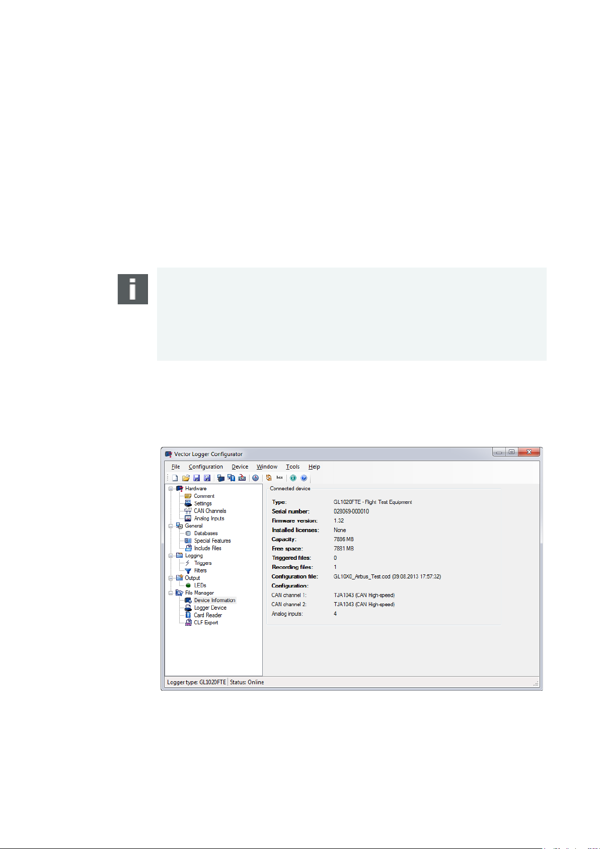
Figure 6 – Overview of connected device
Data Upload
13. Start the Vector Logger Configurator again.
14. Connect the logger to the PC via USB cable.
15. Open the File Manager node in the tree view.
16. Click on Logger Device. Now the logging files are displayed.
17. Select in the General Settings the destination folder and the format for the
converted files.
18. Select in the Advanced Settings the options for conversion.
19. Click on the [Convert] button to start the readout and conversion of all data. The
files will be located in <Destination folder>/< Destination
Note: The logger deletes the file system on the SD card on start of logging mode if it
exists. The logger uses its own file system that cannot be seen in the Windows
Explorer. It is required to use the Vector Logger Configurator to download a
configuration and upload logging files.
Windows 7 / Windows 8.1 / Windows 10: After connecting the logger a message is
displayed whether the memory card in Drive x shall be formatted. Always cancel this
Read device
information
Screenshot
The Vector Logger Configurator reads out hardware information from the logger like
hardware configuration, serial number, firmware version, free memory space, number
Connect the GL1020FTE via USB and select the item File Manager|Device
© Vector Informatik GmbH Version 1.5 - 18 -
Page 21

User Manual GL1020FTE Avionic Logger Start-Up/Commissioning
acknowledge any CAN messages in the acknowledge slot of the CAN bus.
transceiver will soon change into bus off state.
is a purely passive recorder.
mode
power loss. This may lead to the following situation if the logger is in sleep mode:
sleep mode. All LEDs are off.
How to restart the logger:
> After switching power off: wait some seconds before switching power on again.
3.4 Evaluation Notes
Test simulation The GL1020FTE is unable to send on the CAN buses to prevent the logger from
disturbing the aircraft CAN bus in any way. This also implies, that the logger will not
Therefore operating a single device and the logger in a test place for example is not
possible, as the device will never get its messages acknowledged and its CAN
Operating the logger in an evaluation setup with CANoe will require using two CAN
channels of CANoe in order to have all sent messages acknowledged, as the logger
Power on/off in Sleep
If power is switched off and immediately switched on again, the logger still remains in
The logger is equipped with a capacitor to bridge a time gap of approx. 0.5 second of
> A CAN message is required to wake up the logger.
OR:
> Connect the USB cable. The logger is now in the configuration mode. Disconnect
it after some seconds. The logger restarts again.
OR:
© Vector Informatik GmbH Version 1.5 - 19 -
Page 22

Page 23

User Manual GL1020FTE Avionic Logger Functions
4 Functions
In this chapter you find the following information:
4.1 Operating Modes page 22
4.2 Wake-up / Sleep page 22
4.3 LED Display page 22
4.4 Analog Inputs page 23
4.5 Beep page 24
4.6 Storage Media page 24
4.7 Real-Time Clock with Battery page 24
4.8 Lightning and Overvoltage Protection page 24
4.9 Technical Data page 26
4.10 Included with Delivery page 26
© Vector Informatik GmbH Version 1.5 - 21 -
Page 24

User Manual GL1020FTE Avionic Logger Functions
USB connection and power supply respectively.
SD card can be uploaded to the PC.
DSUB25 connector.
> Using a wake-up timer via real-time clock
for a defined time. This time can be configured (max. 18000 s = 5 h).
to display different states. LED USB indicates the USB connection to the PC.
LED 1
Green
Yes
LED 4
Red
Yes
4.1 Operating Modes
Overview The GL1020FTE supports two operating modes, which are switched by using the
USB connection Voltage supply Mode
Yes Optional Configuration mode
No Required Logging mode
Configuration mode
Logging mode
In the Configuration mode the logger can be configured with the configuration
program. The configuration can be downloaded to the logger. Logging data from the
The Logging mode enables the PC independent usage of the logger and allows the
logging of CAN and analog values. For this case the logger must be unplugged from
the USB connector of the PC. The voltage supply has to be provided externally by the
4.2 Wake-up / Sleep
Wake-up The GL1020FTE starts automatically after power on.
A sleeping logger wakes up
> After reception of a CAN message
Sleep
The logger can be configured to go to sleep mode if no CAN messages are received
4.3 LED Display
LED display The logger has five LEDs. LED 1 to LED 4 are free programmable. They can be used
© Vector Informatik GmbH Version 1.5 - 22 -
LED Color Programmable
LED 2 Yellow Yes
LED 3 Red Yes
LED USB Green No
Page 25

User Manual GL1020FTE Avionic Logger Functions
Note, that this LED is not programmable.
LEDs 1–4
In the following situation in the Logging mode the display of LEDs 1–4 is fix.
separately.
Technical data
channel.
LED USB This LED displays the state of the USB connection between the logger and the PC.
State Meaning
On USB connected and SD card inserted. The logger is
registered on the PC and ready for data transfer via USB.
Slow blinking
(1 Hz)
Fast blinking Data transfer
Off All other cases
USB connected, but SD card is not inserted.
The logger is registered on the PC. Due to missing SD
card no data transfer is possible.
State Meaning
Simultaneous slow
blinking of LEDs 1–4
Fault due to missing or defective SD card.
4.4 Analog Inputs
Analog inputs The logger has four independent analog channels which can be configured
Averaging
Voltage range
Resolution
Precision
Sampling rate
Type
Input resistance
Reverse-polarity protection
It is possible to average the measured analog inputs over a defined sampling period
between 1 kHz and 1 Hz. E.g. for a 1 Hz sampling frequency, the measured values
are averaged over the last second. The internal sampling rate is 1 kHz for each
0 V … 16 V
10 bit
1 %
Max. 1 kHz
Single-ended to ground
155.6 kΩ
-50 V … +50 V
© Vector Informatik GmbH Version 1.5 - 23 -
Page 26

User Manual GL1020FTE Avionic Logger Functions
trigger. Triggers and beep can be defined using the configuration program.
Due to the closed housing the signal tone of the speaker is only limited audible.
via USB to the PC to configure the logger and to read-out the stored logging files.
logged data. Additionally it can be used to wake-up the logger.
T = -40°C to +40°C in the rest of the time
in Germany).
are protected against indirect lightning effects and voltage spikes.
4.5 Beep
Beep The GL1020FTE has a speaker that acoustically alerts the user e.g. in case of a
4.6 Storage Media
Memory card The GL1020FTE supports SD cards up to 2 GB and SDHC cards up to 32 GB.
An 8 GB SDHC card is already included and mounted inside the logger by default. Up
to 400 million CAN messages with DLC 8 can be recorded. Other card sizes can be
chosen when ordering a GL1020FTE.
The SD card cannot be accessed from the outside of the logger. Connect the logger
4.7 Real-Time Clock with Battery
Real-time clock The GL1020FTE has an internal real-time clock, which is battery supplied, and thus
continues running even if the logger is disconnected from power supply. The real-time
clock inside the logger is only required to store the date and time together with the
Battery The battery has a typical durability of approximately 5-10 years under the following
conditions:
T = +40°C to +80°C for at most 40 hours per week
Dispose of the removed battery according to the applicable laws (e.g. the Battery Law
4.8 Lightning and Overvoltage Protection
Protection The following block diagram shows that power supply, CAN bus and analog inputs
© Vector Informatik GmbH Version 1.5 - 24 -
Page 27

User Manual GL1020FTE Avionic Logger Functions
Figure 7 – Protection diagram
functional upset tests are taken into account.
> Power Supply: WF5A at 125 V/125 A and WF3 at 250 V/10 A
section 17 of RTCA DO-160E with up to 600V/12A.
Protection diagram
The GL1020FTE is designed to withstand the effects of indirect lightning as described
in section 22 of RTCA DO-160E. The requirements of damage tests as well as
The following waveforms are considered:
> CAN & Analog In: WF5A at 125 V/125 A and WF3 at 50 V/2 A
The power supply is additionally protected against voltage spikes as described in
© Vector Informatik GmbH Version 1.5 - 25 -
Page 28

User Manual GL1020FTE Avionic Logger Functions
up time.
> USB cable
4.9 Technical Data
PC interface
CAN Channels
Analog inputs
Start-up time
Altitude
Temperature range
Power supply
Shut-down voltage
Power consumption
Current consumption
Dimensions (LxWxH)
USB 2.0
2 channels with high-speed transceiver TJA1043,
up to 1,000 kbit/s
4 inputs:
- Resolution 10 bit (1% precision)
- Sampling rate max. 1 kHz
- Voltage range 0 V…16 V
Approx. 300 ms (with 8 GB SDHC card)
Up to 36,000 ft
-40 °C…+85 °C (data upload -15 °C…+70 °C)
9 VDC…33 VDC (28 VDC typ., supply dropouts up to
200 ms tolerated)
4.5 V
Typ. 660 mW
Max. 1100 mW
Sleep mode: < 1 mA
Operation: typ. 23 mA at 28 VDC
Approx. 208 mm x 120 mm x 37 mm
(including mounting plate)
Weight
Housing
Battery
Start-up time
Data is recorded after the given start-up time if the GL1020FTE already contains a
configuration. Updating the configuration or using a new SD card increases this start-
4.10 Included with Delivery
Standard scope of
delivery
> GL1020FTE Logger with built-in SDHC card
> Vector Logger Configurator on CD
> G.i.N. configuration program on CD
> Manuals on CD
> Avionic evaluation cable
Approx. 495 g
RAL 2004 color
Lithium primary cell, BR2032 type
© Vector Informatik GmbH Version 1.5 - 26 -
Page 29

User Manual GL1020FTE Avionic Logger Index
5 Index
A
Analog inputs ...................................................... 23
B
Battery................................................................. 24
Beep.................................................................... 24
Bonding point ...................................................... 15
C
Configuration mode ............................................ 22
Connection cable ................................................ 15
Connectors ......................................................... 12
D
Delivery ............................................................... 26
Device information .............................................. 18
DSUB25 .............................................................. 13
E
Evaluation notes ................................................. 19
M
Mounting plate ................................................... 15
O
Operating modes ............................................... 22
P
Pin assignment .................................................. 13
Q
Quick start .......................................................... 17
R
Real-time clock .................................................. 24
S
SD/SDHC memory card ..................................... 24
Sleep .................................................................. 22
Start-up .............................................................. 11
Start-up time ...................................................... 26
Storage media .................................................... 24
F
Functions ............................................................ 21
I
Installation Logger Configurator ......................... 16
L
LED ..................................................................... 22
Lightning Protection ............................................ 24
Logging mode ..................................................... 22
Support ................................................................ 5
T
Technical data .................................................... 26
V
Vector Logger Configurator ............................... 16
W
Wake-up ............................................................. 22
© Vector Informatik GmbH Version 1.5 - 27 -
Page 30

More Information
> News
> Products
> Demo Software
> Support
> Training Classes
> Addresses
www.vector.com
 Loading...