

Page 1

>> User manual
FRstress
FlexRay Stress Module
Version 1.0
> English
Page 2

A
Imprint
Vector Informatik GmbH
Ingersheimer Straße 24
D-70499 Stuttgart
The information and data given in this user manual can be changed without prior notice. No part of this manual may be reproduced in
any form or by any means without the written permission of the publisher, regardless of which method or which instruments, electronic
or mechanical, are used. All technical information, drafts, etc. are liable to law of copyright protection.
© Copyright 2006, Vector Informatik GmbH
ll rights reserved.
80291
Page 3

User manual FRstress Table of contents
Table of contents
1 Preliminary Notes 3
1.1 About this user manual 4
1.1.1 Access helps and conventions 4
1.1.2 Certification 5
1.1.3 Warranty 5
1.1.4 Support 5
1.1.5 Registered trademarks 5
2 Introduction 7
2.1 Overview 8
2.2 Installation of FRstress 9
2.2.1 Driver installation 9
2.2.2 Check driver installation 9
2.2.3 Software installation 9
2.2.4 FRstress online help 10
2.3 Basic concepts of FRstress 10
2.3.1 Trigger definition 10
2.3.2 Operation modes 11
3 FRstress Configuration Software 13
3.1 Overview 14
3.2 Menus 14
3.2.1 File 14
3.2.2 Disturbance 15
3.2.3 Options 15
3.2.4 Help 16
3.3 Toolbar and Shortcuts 16
3.4 Configuration tree 16
3.5 Configuration pages 17
3.5.1 Hardware Unit 17
3.5.2 Trigger/Disturbance 1-4 19
3.5.2.1 Trigger Parameters 21
3.5.2.2 Digital Disturbance 21
3.5.2.3 Analog Disturbance 22
3.5.2.4 Disturbance Parameter 23
3.5.3 Continuous Disturbance 23
3.5.4 Analog Disturbance 23
3.5.5 Trigger Input 25
3.5.6 Trigger Output 25
3.6 Message and Status window 26
3.7 FRstress COM Interface 26
4 FRstress Hardware 27
4.1 Interfaces 28
4.1.1 Y-Adapter to the FlexRay bus 28
4.1.2 Trigger Output 28
4.1.3 Trigger Input 28
4.1.4 Sync Line 28
© Vector Informatik GmbH Version 1.0 - I -
Page 4

Table of contents User manual FRstress
4.1.5 USB 29
4.1.6 Power Connector 29
4.2 LED Indicators 29
5 Technical Data 31
5.1 General 32
5.2 Trigger Input 32
5.3 Trigger Output 32
6 Appendix A: Firmware Update 33
7 Appendix B: Vector.ini 34
8 Appendix C: Address Table 35
9 Index 37
- II - Version 1.0 © Vector Informatik GmbH
Page 5

User manual FRstress Preliminary Notes
1 Preliminary Notes
This chapter contains the following information:
1.1 About this user manual page 4
Access helps and conventions
Certification
Warranty
Support
Registered trademarks
© Vector Informatik GmbH Version 1.0 - 3 -
Page 6
About this user manual User manual FRstress
1.1 About this user manual
1.1.1 Access helps and conventions
To find information
quickly
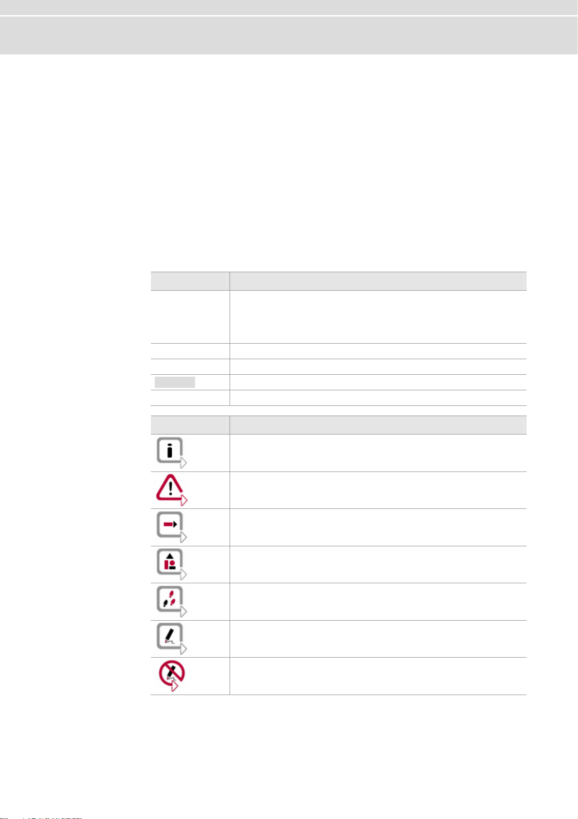
Conventions The following two charts show the spelling and symbol conventions used in this
This user manual provides you with the following navigational aids:
¼ At the beginning of each chapter you will find a summary of the contents
¼ The header shows which chapter and paragraph you are located in
¼ The footer shows which version the user manual refers to
¼ The index, located at the end of the manual on page , helps you to find
information quickly
manual.
Style Utilization
bold
FRstress Legally protected proper names and side notes.
Source code
Hyperlink Hyperlinks and references.
<STRG>+<S> Notation for keyboard shortcuts.
Fields, interface elements, window and dialog names in the
software. Accentuation of warnings and notes.
[OK] Buttons are denoted by square brackets
File | Save Notation for menus and menu entries
File name and source code.
Symbol Utilization
You can obtain supplemental information here.
This symbol calls your attention to warnings.
You can find additional information here.
Here is an example that has been prepared for you.
Step-by-step instructions provide assistance at these points.
Instructions on editing files are found at these points.
This symbol warns you not to edit the specified file.
- 4 - Version 1.0 © Vector Informatik GmbH
Page 7

User manual FRstress Preliminary Notes
1.1.2 Certification
Certified Quality
Management System
Vector Informatik GmbH has ISO 9001:2000 certification. The ISO standard is a
globally recognized standard set by the British Standards Institution.
1.1.3 Warranty
Limitation of warranty We reserve the right to change the documentation and software without prior notice.
Vector Informatik GmbH assumes no liability for the correctness of the contents or for
any damages that may arise from use of this manual. We are always grateful for
references to mistakes or for suggestions for improvement, so as to be able to offer
you even better-performing products in the future.
1.1.4 Support
Need support? Our business hours are Monday to Friday from 9:00 am to 5:00 pm (CET):
¼ telephone: +49 711 80670-200
¼ fax: +49 711 80670-555
¼ email: support@vector-informatik.de
1.1.5 Registered trademarks
Registered
trademarks
All trademarks mentioned in this user manual, including those registered to third
parties, are governed by the respective trademark laws and are the property of their
respective owners. All trademarks, trade names or company names are or can be
trademarks or registered trademarks of their particular owners. All rights which are
not expressly allowed are reserved. Failure to explicitly note any given trademark
within this user manual does not imply that a third party does not have rights to it.
¼
Windows, Windows XP, Windows 2000, Windows NT, Visual Basic, Visual
SourceSafe
are trademarks of the Microsoft Corporation.
© Vector Informatik GmbH Version 1.0 - 5 -
Page 8

Page 9
User manual FRstress Introduction
2 Introduction
In this chapter you find the following information:
2.1 Overview page 8
2.2 Installation of FRstress page 9
Driver installation
Check driver installation
Software installation
FRstress online help
2.3 Basic concepts of FRstress page 10
Trigger definition
Operation modes
© Vector Informatik GmbH Version 1.0 - 7 -
Page 10
Overview User manual FRstress
2.1 Overview
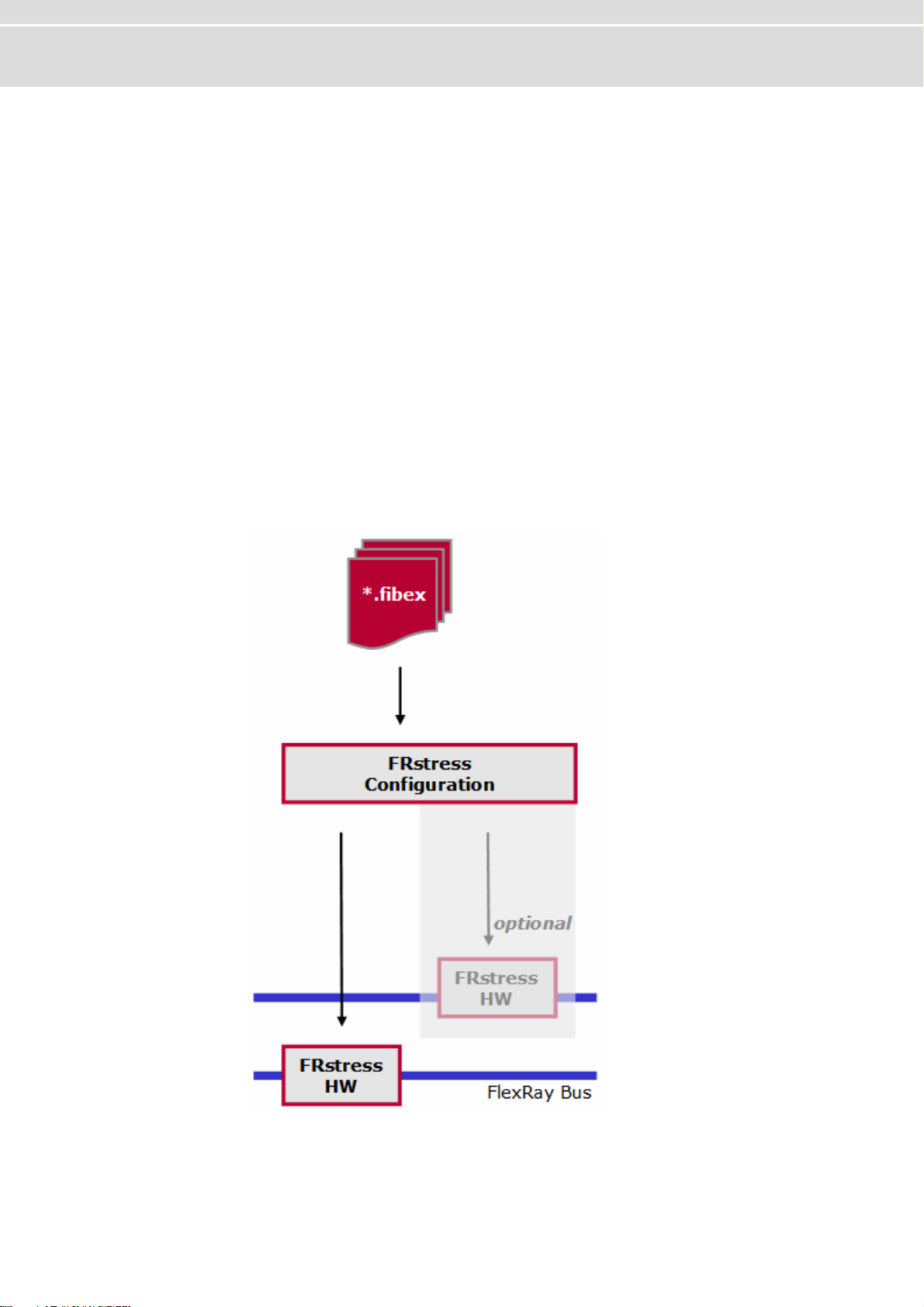
At a glance With FRstress the user can intentionally and reproducibly disturb the FlexRay bus, its
physical characteristics and the logical level.
The test scenarios consist of the definition of trigger conditions and corresponding
The graphic shows the block diagram of
FRstress block
diagram
FRstress offers the following capabilities:
¼ Forcing shortcuts between the bus lines, power or ground
¼ Disturbing specific messages
¼ Manipulating single bit fields of a FlexRay messages
¼ Frame deletion
¼ Frame delay
actions like disturbance or activation of a trigger output. With the start of
measurement a set of four tests can be transferred to the hardware for execution.
Although hardware can only disturb one channel it is possible to configure test
scenarios for both channels of a FlexRay cluster. The software provides the support
of two hardware devices.
FRstress:
- 8 - Version 1.0 © Vector Informatik GmbH
Page 11

User manual FRstress Introduction
2.2 Installation of FRstress
Overview To work with FRstress you have to install:
1. The USB driver of the hardware unit.
2. The FRstress configuration software.
2.2.1 Driver installation
Install driver 1. Connect FRstress to the PC with a USB cable.
Found New HardwareWindows starts the wizard.
Please follow the instructions found there.
2. Choose
3. Click the [Next] button.
4. During installation by CD you must specify the location of the drivers by clicking
[Browse].
Therefore please select
You will find the files required for driver installation in the directory:
5. Please click the [Next] button and follow the instructions of the Hardware.
The wizard finishes its work with a confirmation of success.
Install from a list or specific location.
Include this location in the search.
\Drivers
2.2.2 Check driver installation
Check driver 1. Start the Device Manager.
2. Check to see whether the device Vector
Vector Hardware.
3. Verify the proper installation by double clicking the Vector FRstress item.
After the successful installation of the driver you will see the device status “
device is working properly
” on the General page.
FRstress is shown as a subgroup of
This
2.2.3 Software installation
Install software Proceed as follows to install the FRstress configuration software:
1. Insert the installation CD in your CD drive.
2. Call up the installation program SETUP.EXE.
3. Follow the instructions of the installation program.
Info: The language of the menus and dialogs can be switched at any time after the
installation (see Appendix B: Vector.ini, page ).
© Vector Informatik GmbH Version 1.0 - 9 -
Page 12
Basic concepts of FRstress User manual FRstress
2.2.4 FRstress online help
Access the online
help file
FRstress provides a comprehensive online help function which can be called from the
Help [Help] menu, the button or the <F1> key.
Info: If you choose the Help|Using Help command or press the <F1> key while
FRstress online Help is active, you get information on using and configuring the
online help function.
2.3 Basic concepts of FRstress
Basic Concepts For the test and the validation of FlexRay networks and ECUs it is important to
analyze the behavior in presence of errors.
reproducible disturbances in the FlexRay network. Disturbances on protocol level as
well as disturbances on physical level are possible.
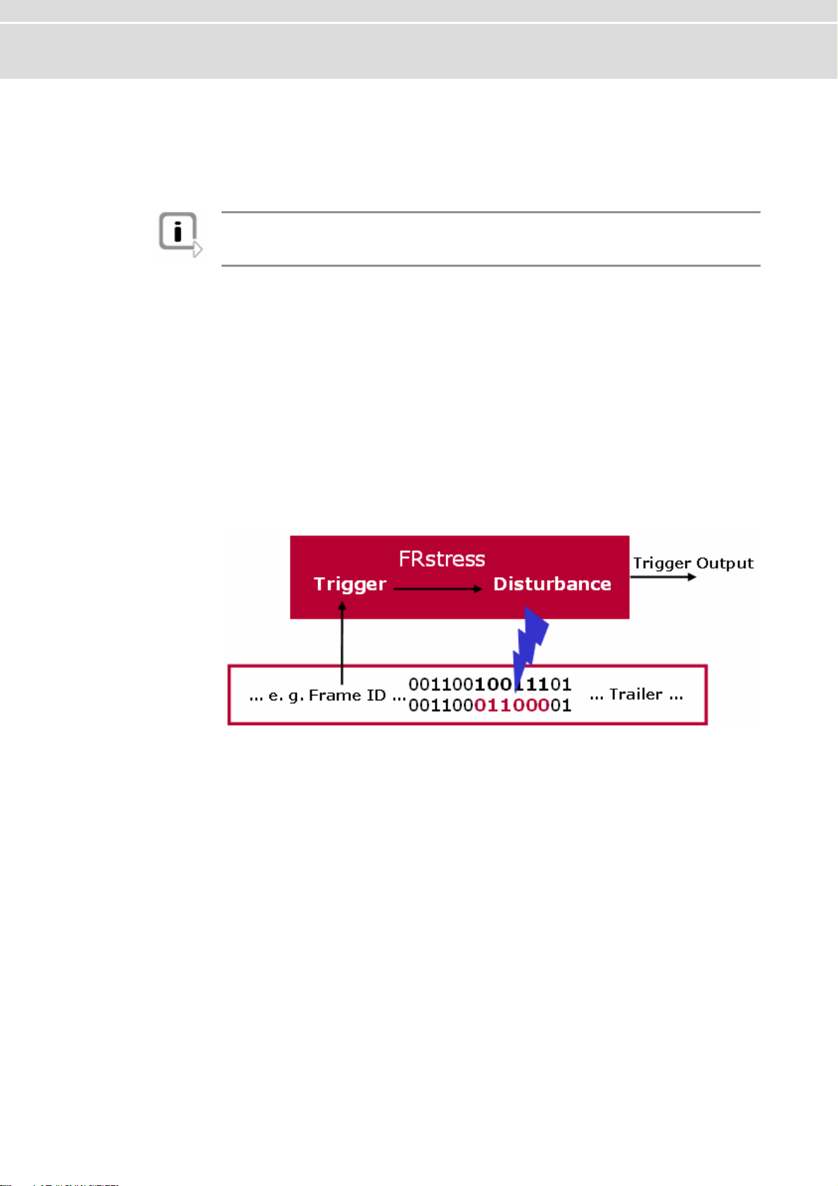
The graphic below demonstrates the basic function of
analyzes the bit stream on the FlexRay bus and compares the data with the active
trigger streams. As soon as a trigger condition matches, the trigger output is
activated. Additionally to the active trigger signal a dedicated disturbance manipulates
the FlexRay bus. The kind of disturbance depends on the active operation mode of
FRstress.
Basic Functions
FRstress supports you to generate
FRstress. The hardware
FRstress provides three different operation modes. The following chapters give an
overview about the trigger definition and the operation modes.
2.3.1 Trigger definition
Trigger Definitions Altogether four parallel trigger definitions can be defined. The trigger is defined by a
sequence of
bus the trigger will be activated.
The software provides a FlexRay frame oriented input mask for the trigger definition.
All elements of the FlexRay frame and the frame coding (e.g. Byte Start Sequence)
are available for the trigger definition.
These are examples for possible trigger definitions:
- 10 - Version 1.0 © Vector Informatik GmbH
0, 1 don’t care and . With the detection of this sequence on the FlexRay
Page 13
User manual FRstress Introduction
FlexRay frame in a certain slot
FlexRay frame in a certain slot and
cycle number
All sync frames
The field frame ID of the frame header
must be filled up with the desired slot
number.
The fields frame ID cycle number and of
the frame header must be filled up with
the desired values.
The field Sync flag indicator of the
frame header must be set to
1.
2.3.2 Operation modes
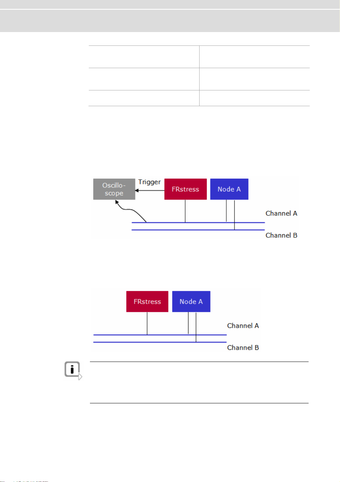
Pure Scope Mode In this mode FRstress is passive to the FlexRay bus. It analyses the bit stream on the
bus and generates the appropriate trigger signals. The disturbance part is switched
off.
This mode is useful for pure triggering where no disturbances are required. An
oscilloscope is a typical receiver of the trigger signal.
Analog Connection
Mode
Additionally to the trigger definition it is possible to define disturbance sequences.
These sequences will be activated after the detection of the assigned trigger. This
means that the earliest point in time for the start of a disturbance sequences is
immediately after the trigger the detection of the last trigger bit.
FRstress is connected to the bus in normal node.
Info: In this mode the transceivers of FRstress transmit in one case against the
transceiver of the sending node and in the other case with the sending transceiver.
This is reflected in the fact that depending on the line position in some case the
desired disturbance can not guaranteed. This means the disturbance can be
influenced by the length of the bus cable, the termination, the transceivers and the
position of the receiver node.
© Vector Informatik GmbH Version 1.0 - 11 -
Page 14

Basic concepts of FRstress User manual FRstress
The functions of this mode are:
¼ Injection of disturbance pattern after a trigger.
This can be used to destroy a specific frame. In this mode a bit synchronous
frame manipulation is not possible.
¼ Modification of the bus physics through the configuration of additional resistors
between the bus lines, parallel to the bus lines, to ground and power supply.
This is useful for the simulation of various line lengths, shortcuts to ground or
power supply and different capacities.
Digital Connection
Mode
FRstress divides the network into two segments. The hardware operates similar to an
active star. Frames will be transmitted from one segment to the other segment and
vice versa. In contrast to the
accuracy are possible too. The optional CRC recalculation completes the function set
in that way that bit accurate manipulations are possible. E.g. the Sync flag of a Sync
frame from segment A can be set to 0 and the frame CRC will be recalculated. The
receiver segment B sees now a valid frame without a sync flag set.
Additional functions are:
Frame filter between
the segments
Frame delay
between the
segments
Analog Connection Mode disturbances with bit
Extension of the
Transmission Start
Sequence
- 12 - Version 1.0 © Vector Informatik GmbH
Page 15

User manual FRstress FRstress Configuration Software
3 FRstress Configuration Software
In this chapter you find the following information:
3.1 Overview page 14
3.2 Menus page 14
File
Disturbance
Options
Help
3.3 Toolbar and Shortcuts page 16
3.4 Configuration tree page 16
3.5 Configuration pages page 17
Hardware Unit
Trigger/Disturbance 1-4
Continuous Disturbance
Analog Disturbance
Trigger Input
Trigger Output
3.6 Message and Status window page 26
3.7 FRstress COM Interface page 26
© Vector Informatik GmbH Version 1.0 - 13 -
Page 16

Overview User manual FRstress
3.1 Overview
Overview The configuration software window consists of 6 parts:
1. Menu bar
2. Toolbar
3. Configuration tree
4. Configuration pages
5. Message/Status window
6. Status bar
Main Window
with 6 parts
3.2 Menus
3.2.1 File
File menu The File menu provides commands for loading and saving configurations, for
associating a data-base and for exiting the program.
- 14 - Version 1.0 © Vector Informatik GmbH
New
An empty configuration is created.
Open
A previously saved program configuration can be read from a file.
Page 17

User manual FRstress FRstress Configuration Software
Save
The entire program configuration can be saved to file.
All trigger and disturbance settings are written to a file.
Save as…
The active configuration can be saved to a new directory and/or with a new name.
Associate database…
In this dialog you define which FIBEX databases you wish to work with.
Exit
This menu entry closes
FRstress.
3.2.2 Disturbance
Disturbance menu The Disturbance menu provides the commands for the disturbance control.
Start
The disturbance scenario will be transferred to the hardware and the hardware
starts its execution.
The connection to the hardware will be set automatically.
Trigger Hardware Unit 1
This command executes the software trigger of the
This function is available only during a measurement session and if the software
trigger is configured on the trigger input configuration page.
FRstress hardware 1.
Trigger Hardware Unit 2
This command executes the software trigger of the
This function is available only during a measurement session and if the software
trigger is configured on the trigger input configuration page.
Stop
The measurement is stopped by selecting this menu item or by pressing the
<ESC> key.
It can be restarted afterwards by pressing <F9> key.
FRstress hardware 2.
3.2.3 Options
Options menu The Options menu switches between one and two hardware support.
Use one channel configuration
This menu item activates the one hardware support.
The disturbance scenario for one channel can be configured.
Use two channel configuration
This menu item activates the two hardware support.
The disturbance scenario for two channel can be configured.
To start the disturbance scenario two hardware units must be available.
Use Autoselect status tab on start
When this option is selected, the status tab of the status window will automatically
be selected when starting a trigger/disturbance.
Use Autoselect hw unit overview
When this option is selected, the correct overview tab of the status window will
automatically be selected depending on the cursor position in the selection tree
on the left side of the main window
© Vector Informatik GmbH Version 1.0 - 15 -
Page 18

Toolbar and Shortcuts User manual FRstress
3.2.4 Help
The Help menu provides the contents of Help menu FRstress’ context-sensitive help function.
Contents
About…
The [More Info] button in the disclaimer window displays the serial number, the
firmware version, the DLL version and the driver version in the info tab of the
Status window.
3.3 Toolbar and Shortcuts
Toolbar /
Shortcuts
The global toolbar contains general FRstress functions. In addition, it includes
functions for starting and stopping measurement.
Symbol Description Menu command Key(s)
New <Ctrl>+<N>
Open <Ctrl>+<O>
Save <Ctrl>+<S>
Start <F9>
Stop <ESC>
Trigger Hardware
Unit 1
Trigger Hardware
Unit 2
About —
Help contents <F1>
File|New
File|Open
File|Save
Disturbance|Start
Disturbance|Stop
Disturbance|Trigger Hardware
Unit 1
Disturbance|Trigger Hardware
Unit 2
Help | About
Help | Contents
<F7>
<F8>
3.4 Configuration tree
Configuration tree The tree view on the left side allows the navigation between the different configuration
FRstress.
Special case for sequence 1: In case of that the disturbance sequence 1 is
used by the software trigger a deactivation is not possible. A yellow symbol is
displayed to show that the trigger is not used but the disturbance part.
Trigger Disturbance
1−4
Continuous
disturbance
Analog disturbance
pages of
The selection of this entry activates the Trigger/disturbance configuration. A double
click on this entry activates (green symbol) or deactivates (red symbol) the
Trigger/disturbance set.
Definition of a special disturbance sequence (see 3.5.3 Continuous Disturbance,
page ).
This entry activates the configuration page resistor and capacity network (see 3.5.4
Analog Disturbance, page ).
- 16 - Version 1.0 © Vector Informatik GmbH
Page 19

User manual FRstress FRstress Configuration Software
Trigger Input This entry activates the configuration page for the external and the software trigger
(see 3.5.5 Trigger Input, page ).
Trigger Output This entry handles the source and the level configuration of the trigger output (see
3.5.6 Trigger Output, page ).
3.5 Configuration pages
3.5.1 Hardware Unit
Hardware Unit page This configuration page holds the definition of the global configuration of the FRstress
environment.
Channel Assignment The connected FlexRay channel (Channel A or Channel B).
This setting is important for the dynamic CRC calculation function (see 3.5.2.4
Disturbance Parameter, page ).
Bus Connection
Modes
With the several connection modes (Digital Connection Mode, Analog Connection
Mode, Pure Scope Mode) different functions are available:
¼ Digital Connection Mode
FRstress divides the bus into two segments. It observes the communication and
can influence the bus with disturbances on bit level.
Main functions in this mode are:
¼ Frame modification on bit level
¼ Dynamic CRC calculation after a Frame modification
¼ Frame deletion from one segment to the other segment
¼ Frame delay from one segment to the other segment
¼ Extension of the Transmission Start Sequence (TSS) part of a frame.
¼ Analog Connection Mode
FRstress is connected as usual node. In this connection mode are available:
¼ Resistor and capacity modification
¼ Asynchronous disturbances
© Vector Informatik GmbH Version 1.0 - 17 -
Page 20

Configuration pages User manual FRstress
¼ Pure Scope Mode
In the Pure Scope Mode only the trigger functions are available. The bus
connection in this mode realizes a connection with a minimal influence to the bus.
Network Parameters
¼ Baudrate
For all modes the appropriate baud rate has to be selected. For each baud rate a
dedicated firmware must be downloaded to the hardware (see 6 Appendix A:
Firmware Update, page ).
¼ Payload Length
This field contains the payload length in bytes of the static frames in the network.
All payload fields in the trigger and disturbance configuration pages will be preset
with this number.
¼ For Digital Connection Mode only
These settings are only available in the Digital Connection Mode. Otherwise
they are inactive
¼ Macrotick Length
¼ TSS Length
¼ Cycle Length
¼ Number Static Slots
¼ Action Point Offset
¼ Static Slot Length
The [Get database values] button extracts all values described above from the
assigned FIBEX database.
- 18 - Version 1.0 © Vector Informatik GmbH
Page 21

User manual FRstress FRstress Configuration Software
These settings are only available in the Digital Connection Mode: Digital Connection
Mode
¼ Frame Delay
Incoming frames will be delayed before they are sent to the output segment.
¼ TSS Extension
At the output segment all frames will be sent with the extended Transmission
Start Sequence.
¼ Frame Deletion
This filter blocks for the output segment all frames specified with frame id and
cycle number. The concrete number and the wildcard symbol x are valid input
values.
3.5.2 Trigger/Disturbance 1-4
Overview The configuration tree offers four sets of Trigger and Disturbances.
Each of these sets has several configuration pages.
Frame Trigger page On this page a trigger is to be defined for a disturbance. All fields of a FlexRay
message can be used. Each trigger bit can have the values Data_0 (0), Data_1 (1) or
don’t care (x). For frame ID, payload length, header CRC, cycle count, CRC 1, CRC 2
and CRC 3 the values can be entered numerical (hex or dec) by clicking on the link
left of the corresponding edit box.
© Vector Informatik GmbH Version 1.0 - 19 -
Page 22

Configuration pages User manual FRstress
Header Sequence
Field Length Range
Reserved Bit
Payload preamble indicator
Null frame indicator
Sync frame indicator
Startup frame indicator
FrameID 11 bit 1…2047
Payload Length 7 bit 0…127 words
Header CRC 11 bit —
Cycle Count 6 bit 0…63 cycles
BSS1–BSS5 2 bit Default bit sequence: 10
1 bit —
Option Description
Use Frame ID Forecast /
Use Cycle Count
Forecast
The forecast functions can only be used in Digital
Connection Mode.
The purpose of the forecast mechanism is to trigger on
bits in a particular frame which are located before the
frame id/cycle count.
To use the forecast function, at first it has to be to
defined which frame id /cycle count shall be forecasted.
Then trigger bits have to be defined which are located
before frame id/cycle count in the frame. These bits
define the place where the trigger occurs.
When a forecast mechanism is activated, the frame id
and/or the cycle count are not treated as trigger bits.
Note that the network parameters for digital connection
mode have to be specified to use the forecast
mechanism.
Payload Sequence The payload sequence compares only the number of data bytes which is defined in
the list!
Field Length Range
BSS x 2 bit Default bit sequence: 10
Data byte x 8 bit 0…255
Button Description
[Fill Fields]
Fills the payload sequence with “don’t care” bits. The
relevant payload length is taken from the Payload length
field.
- 20 - Version 1.0 © Vector Informatik GmbH
Page 23

User manual FRstress FRstress Configuration Software
Trailer Sequence:
Field Length Range
BSS 1–3 2 bit Default bit sequence: 10
CRC 1–3 8 bit —
FES 2 bit Default sequence: 01
Button Description
[Empty Clear Fields]
[Configurator]
Clears all fields on frame trigger page.
The configurator allows the symbolic configuration of the
Frame ID and Payload length from the database. The
selection dialog lists all FlexRay fames with the
associated node.
¼ Load Frame Id
¼ Load Payload length
¼ Load Frame Id and Payload Length
3.5.2.1 Trigger Parameters
Trigger Parameters Additional parameters for the trigger configuration are located on this page.
Connection Mode
Independent
Digital Connection
Mode
In this section you can configure the trigger count and the delay between the trigger
detection and start of the disturbance.
¼ Disturbance count limitation
If activated the number of triggers can configured in a range between 0 and 255.
The trigger action will be executed unlimited if the setting is deactivated.
¼ Delay after trigger detection
The time between the trigger detection and the start of the disturbance execution
is configurable. The value range is from 0 to 16777215.
Info: When delay after trigger detection is not 0, the analog frame disturbance tab
is activated because a frame synchronous disturbance is only possible when no
trigger delay is set
¼ Auto increment
The delay between the trigger and the disturbance will be incremented
automatically with each trigger occurred. The step size will be set in these fields.
The active port for the trigger detection is modifiable in the Digital Connection
Mode. It is possible to select between both ports, port A and port B.
3.5.2.2 Digital Disturbance
Digital Disturbance
The configured disturbance sequence represents a frame modification on bit level.
© Vector Informatik GmbH Version 1.0 - 21 -
In the Digital Connection Mode this configuration page is active and in the other
connection modes this page is not configurable.
Only those fields that follow the trigger fields (T) can be disturbed.
Page 24

Configuration pages User manual FRstress
As disturbance values for the bits Data_0 (0), Data_1 (1) and undisturbed (u) are
allowed. The frame fields with its meaning and representation are explained on the
Frame Trigger Configuration page. For frame ID, payload length, header CRC,
cycle count, CRC 1, CRC 2 and CRC 3 values can be entered numerical (hex or dec)
by clicking on the link left of the corresponding edit box.
Exception 1: When delay after trigger detection or auto increment isn’t 0 (trigger
parameter page), the analog frame disturbance tab is activated.
Clear fields This button clears all fields on digital frame disturbance page.
Show Trigger Bits This button shows all frame fields which are already used by the trigger definition.
Exception 2: Trigger/Disturbance 1 and Trigger Input → Disturbance sequence 1
is selected → analog frame disturbance tab is activated
These bits can not be used in the disturbance sequence. Normally the disturbance
sequence follows the trigger sequence.
Configurator The selection dialog for database messages is started. A symbolic message can be
selected. The data of the frame will be inserted in the corresponding fields after
selection:
¼ Load Frame Id
¼ Load Payload length
¼ Load Frame Id and Payload Length
Use Continuous
Disturbance
If selected all frame disturbance fields will be deactivated. Instead of the synchronous
disturbance the continuous disturbance is executed when the trigger occurs. The
continuous disturbance can be defined on the corresponding configuration page.
3.5.2.3 Analog Disturbance
Analog Disturbance
This page holds the settings for the disturbance sequence in the Analog Connection
Mode. In all other connection modes this page is deactivated.
The disturbance sequence in the Analog Connection Mode runs asynchronous to
the detected trigger sequence. Due to reflection effects on the bus line it is possible
that not all nodes in the net-work see the same disturbance on the bus.
Exception1: This page is also activated in the digital connection mode, when
delay after trigger detection or auto increment is not 0 (trigger parameter page).
Exception 2: This page is also activated when Trigger/Disturbance 1 and Trigger
Input → Disturbance sequence 1 is selected.
Disturbance
sequence
Frame based input
mask
- 22 - Version 1.0 © Vector Informatik GmbH
The field contains the disturbance sequence. The maximum length is 4095 bits.
In this section you can enter all bit fields of a FlexRay frame. This input mask helps
you to define a disturbance pattern which follows a typical frame pattern. After the
input of the frame the sequence has to be applied to the Disturbance sequence.
Page 25

User manual FRstress FRstress Configuration Software
Calculate Header
CRC
Calculate Frame
CRC
Apply sequence This button copies the entered frame to the disturbance sequence. Fields with free
Reset fields The button resets the fields of the input mask and clears the disturbance sequence.
Use Continuous
Disturbance
This button calculates the Header CRC basing on the fields Startup indicator, sync
frame indicator, slot id, payload length and header CRC.
This button calculates CRC checksum over the complete FlexRay frame including the
header CRC. Important for this calculation is the channel assignment on the hardware
unit page.
undefined bits will be filled up with 0 bits.
If selected all frame disturbance fields will be deactivated. Instead of the synchronous
disturbance the continuous disturbance is executed when the trigger occurs. The
continuous disturbance can be defined on the corresponding configuration page.
3.5.2.4 Disturbance Parameter
Disturbance
Parameters
Dynamic CRC
calculation
Additional parameters for the disturbance can be found on this page.
In the Digital Connection Mode only the dynamic CRC calculation is useful to
produce a valid frame after some bits in the frame have been modified.
Info: The channel setting on the hardware unit page is important for the Dynamic
CRC calculation function.
3.5.3 Continuous Disturbance
Continuous
Disturbance
Disturbance
Sequence
Disturbance
Repetition
Other information The corresponding duration depending on the baud rate and the configuration is
The continuous disturbance consists of a sequence and a repetition.
0…8 bit to define a disturbance pattern.
Number of repetitions of the defined disturbance sequence.
displayed. Additionally to this the list displays the sources that activate the continuous
disturbance.
3.5.4 Analog Disturbance
Analog Disturbance The resistor and capacitor network for analog disturbance is defined here.
Analog disturbances may be caused by the following in a real FlexRay network:
¼ Short circuits
¼ Isolation faults
¼ Poor contacts
© Vector Informatik GmbH Version 1.0 - 23 -
Page 26

Configuration pages User manual FRstress
Disturbance
Parameters
The following disturbance parameters may be used to configure the disturbance
state:
¼ R_HL
for simulating contact resistances between wires (e.g. isolation faults, humidity,
short circuits)
¼ R_H
for simulating contact resistances to disturbance voltages
¼ R_L
for simulating contact resistances to disturbance voltages
¼ R_SH
for simulating length resistances in wiring (e.g. poor contacts or wire breaks)
¼ R_SL
for simulating length resistances in wiring (e.g. poor contacts or wire breaks)
¼ C_HL
for simulating longer bus lines at low baud rates (only makes sense for LowSpeed buses)
Hints Essentially the individual disturbance parameters can be connected or disconnected
by clicking the relevant component in the circuit diagram.
If a resistor is disconnected the associated input field, in which the user enters a
resistor value for this resistor, is disabled for user input.
The resistors and the capacity are active as soon
FRstress is connected to the
hardware. During a disturbance session the values can be modified and manually
adapted with the [Apply to Hardware] button.
Connected
Component
States of the
resistances
Disconnected
Component
The resistances R_SH and R_SL can have the following three states:
Series resistance in the FlexRay line:
R_SH (R_SL) normal in operation
Switched off:
R_SH (R_SL) deactivated and associated switch closed
Break of the FlexRay line:
R_SH (R_SL) deactivated and associated switch open
- 24 - Version 1.0 © Vector Informatik GmbH
Page 27

User manual FRstress FRstress Configuration Software
Disturbance Voltage By default the supply voltage and disturbance voltage are jumpered together in the
supply connector. However, the disturbance voltage can also be fed in separately. In
the circuit diagram you can specify whether the resistor should be connected to the
positive (V_D+) or negative (V_D-) pole of the disturbance voltage; this is done by
clicking the switch next to R_H or R_L. The maximum disturbance voltage that may
be used, and which is utilized to check the configured layout, is displayed next to
Max. disturbance voltage.
3.5.5 Trigger Input
Trigger definition The External Trigger and the Software Trigger can be defined on this page.
Use External Trigger The usage of the external trigger can be switched on or off.
External Trigger
Usage
Use Software Trigger The usage of the software trigger can be switched on or off.
Software Trigger
Action
Software Trigger reaction: In this section the specific behavior of the software trigger
For the external trigger input it is possible to define whether the input should be used
as an external trigger or as a trigger enable signal.
When used as an external trigger the user can choose whether the input should be a
Level trigger (with LOW or HIGH level) or an Edge trigger (with triggering on the
transition from LOW→HIGH or from HIGH→LOW). Additionally the assigned
disturbance can be configured. You can decide for one of the following settings: no
disturbance, disturbance sequence 1 or continuous disturbance.
When used as a trigger enable signal, the user can decide whether, when a trigger
condition is satisfied, there must also be a low (LOW) or a high (HIGH) voltage level
at the input to permit triggering.
This setting describes the general behavior of the software trigger.
¼ Button pressed (single shot trigger):
The trigger is executed by the button pressed action.
¼ Button pressed (on/off functionality):
The software trigger is switched on by the software trigger action and can be
switched off with a second click on the software trigger button.
The assigned disturbance is executed until the trigger is switched off.
is defined.
¼ Trigger disturbance:
As possible disturbances are the disturbance sequence 1 and the continuous
disturbance available.
¼ Trigger enable (when button pressed):
When the software trigger is connected to the trigger output to desired enable
trigger level can be configured: Low or High.
3.5.6 Trigger Output
Trigger Output The trigger output of FlexRay Stress needs an action source and a specific output
level.
© Vector Informatik GmbH Version 1.0 - 25 -
Page 28

Message and Status window User manual FRstress
Activated by The list contains all possible sources which can set the Trigger Output.
A checked item means that the Trigger output is set if a trigger on the specified
source is activated.
The output level Low and High can be selected. Trigger output level
3.6 Message and Status window
Message window In the lower part of the FRstress main window is the message window located. It has
four panes:
Info Notifications, status messages and error are printed into this window.
Status The status pane holds the trigger counter for the sequences 1–4. The counter starts
with the configured number of trigger detections. On each trigger detection the
number is decreased.
Overview unit 1 /
Overview unit 2
The overview pane shows at a glance all configured settings of
FRstress.
3.7 FRstress COM Interface
COM Interface The FRstress COM Server allows you to control FRstress from external programs.
Besides applications, scripts can also be used as external programs. Certainly the
most well-known script and programming languages available to you are: VBScript,
JScript, Perl, VBA, Visual Basic, Delphi and C/C++.
COM configuration Open the MS-DOS console and switch to the FRstress installation directory.
¼ To register the COM Server you have to type
FRstress /register
¼ If you want to unregister the COM Server you have to type
FRstress /unregister
FRstress object
hierarchy
FrsApplication
FrsConfiguration
HardwareUnitCollection
HardwareUnit
TriggerDisturbanceCollection
TriggerDisturbance
AnalogBoard
Cross reference: The online help contains a full description of FRstress related COM
Server elements.
- 26 - Version 1.0 © Vector Informatik GmbH
Page 29

User manual FRstress FRstress Hardware
4 FRstress Hardware
In this chapter you find the following information:
4.1 Interfaces page 28
Y-Adapter to the FlexRay bus
Trigger Output
Trigger Input
Sync Line
USB
Power Connector
4.2 LED Indicators page 29
© Vector Informatik GmbH Version 1.0 - 27 -
Page 30

Interfaces User manual FRstress
4.1 Interfaces
Supported Interfaces The FRstress hardware has the following interfaces:
¼ Y-Adapter to the FlexRay bus
¼ Trigger Output
¼ Trigger Input
¼ Sync Line
¼ USB
¼ Power Connector
4.1.1 Y-Adapter to the FlexRay bus
Bus connection The bus connection is similar to the way CANstress is connected to the bus. An
adapter cable connects the
pin connector to two DB-9 connectors (one male connector and one socket).
FRstress hardware to a bus. The cable converts the 15
Signal DB-9 connector
BM Fr1 2
BP Fr1 7
GND 3
4.1.2 Trigger Output
Trigger Output The trigger output is realized as BNC connector. The output uses the same ground
like the trigger input. The output generates TTL signals.
4.1.3 Trigger Input
Trigger Input The trigger Input is realized as BNC connector. The input accepts TTL signals. The
input is electrically isolated to the remaining hardware.
4.1.4 Sync Line
Sync Line The Sync interface is realized as BNC connector. The sync line interface uses the
same ground like the trigger interfaces. The interface bases on TTL signals.
- 28 - Version 1.0 © Vector Informatik GmbH
Page 31

User manual FRstress FRstress Hardware
4.1.5 USB
USB The USB port is fed out via a four-pin connector (Binder Series 711) and conforms to
the USB standard 2.0.
4.1.6 Power Connector
Power Connector The connector is realized as a 5 pin plug of the plug series “Binder 711”.
Using Pin 5 of the Supply connector it is possible to set the housing ground to a
defined voltage level. When utilized in a motor vehicle, a direct connection to the
negative supply voltage (vehicle ground) presents itself as an option. If relevant to the
specific area of use, it may be advisable to make a connection to the ground
conductor of the installation. If Pin 5 is left unconnected (this is the case on the
voltage cable provided), no voltage level is applied to the housing.
4.2 LED Indicators
Status indication Four LEDs display the current state of the FRstress hardware.
The first LED (Power/Run) is located nearest to the side with the plugs.
Startup mode
Normal mode
The LEDs flash together until the hardware is detected
by the PC.
¼ Power/Run
(flashing)
¼ Trigger-Enable
(On = external trigger is active)
¼ Active
(On = next trigger activates a disturbance)
¼ Disturbance
(On = Generation of a disturbance)
© Vector Informatik GmbH Version 1.0 - 29 -
Page 32

Page 33

User manual FRstress Technical Data
5 Technical Data
In this chapter you find the following information:
5.1 General page 32
5.2 Trigger Input page 32
5.3 Trigger Output page 32
© Vector Informatik GmbH Version 1.0 - 31 -
Page 34

General User manual FRstress
5.1 General
Parameter Conditions Min. Typ. Max. Unit
Ambient temperature
(Operation)
Ambient temperature
(Storage)
Total Weight
Dimension Aluminum case 151 × 168 × 53 mm
(length × width × depth) total 163 × 172 × 57 mm
5.2 Trigger Input
Parameter Conditions Min. Typ. Max. Unit
Threshold voltage: HIGH 2.9 V
Threshold voltage: LOW 1.6 V
Maximum Input Voltage 24 30 V
Input current: HIGH Uin = 24 V 7 mA
Input current: HIGH Uin = 5 V 0 mA
Input current LOW Uin = 0 V −0.4 mA
Continuous current limiting
(thermal)
Isolation voltage to supply 500 V
−10 +70 °C
−40 +85 °C
50 mA
5.3 Trigger Output
Parameter Conditions Min. Typ. Max. Unit
Output voltage HIGH I ≤ +25 mA 2.4 V
Output voltage LOW I ≥ −6 mA 0.6 V
Output current HIGH Uout ≥ 2.4 V 25 mA
Output current LOW Uout ≤ 0.8 V −8 mA
Continuous current limiting
(thermal)
Isolation voltage to supply 500 V
50 mA
- 32 - Version 1.0 © Vector Informatik GmbH
Page 35

User manual FRstress Appendix A: Firmware Update
6 Appendix A: Firmware Update
Firmware Update A new version of the firmware can be updated with a special utility. The command line
tool Ginload.exe downloads the firmware to the hardware. The following command
has to be entered in the command line:
If available new versions of the Backup Firmware (FRSB_xxx.cod) and the Bootcode
If more than one of these files is new the download order is important:
GiNload -vV xxx.cod (for example: GiNload -vV FRS_028.cod)
(FRSBCxxx.cod) can be downloaded in the same way by calling Ginload.exe:
GiNload -vV FRSB_028.cod
GiNload -vV FRSBC028.cod
1. Firmware
GiNload -vV FRS_xxx.cod
2. Backup firmware
GiNload -vV FRSB_xxx.cod
3. Bootcode
GiNload -vV FRSBCxxx.cod
© Vector Informatik GmbH Version 1.0 - 33 -
Page 36

Appendix B: Vector.ini User manual FRstress
7 Appendix B: Vector.ini
Vector.ini The following options for FRstress can be configured in VECTOR.INI:
Language of the menus and dialogs (Section:
[Language]
Country=01
Info: If the language of your Windows version is not the same as the language set for
FRstress, certain dialogs and buttons may appear in the language of your Windows
version.
For example, if you have configured English as the language for
German version of Windows, the German dialog Öffnen (Open) appears, since
Windows resources are referenced here.
[Language] Country=, Line: )
FRstress under a
- 34 - Version 1.0 © Vector Informatik GmbH
Page 37

User manual FRstress Appendix C: Address Table
8 Appendix C: Address Table
Vector Informatik
GmbH
Vector Consulting
GmbH
Vector CANtech, Inc. Vector CANtech, Inc.
Vector Informatik GmbH
Ingersheimer Str. 24
D-70499 Stuttgart
Phone: +49 (711) 80670-0
Fax: +49 (711) 80670-111
mailto:info@vector-informatik.de
http://www.vector-informatik.com/
Vector Consulting GmbH
Ingersheimer Str. 24
D-70499 Stuttgart
Phone: +49 (711) 80670-0
Fax.: +49 (711) 80670-444
mailto:info@vector-consulting.de
http://www.vector-consulting.de/
Suite 550
Vector Japan Co.,
Ltd.
39500 Orchard Hill Place
USA-Novi, Mi 48375
Phone: +1 (248) 449 9290
Fax: +1 (248) 449 9704
mailto:info@vector-cantech.com
http://www.vector-cantech.com/
Vector Japan Co., Ltd.
Seafort Square Center Bld. 18F
2-3-12, Higashi-shinagawa, Shinagawa-ku
J-140-0002 Tokyo
Phone: +81 3 (5769) 6970
Fax: +81 3 (5769) 6975
mailto:info@vector-japan.co.jp
http://www.vector-japan.co.jp/
© Vector Informatik GmbH Version 1.0 - 35 -
Page 38

Appendix C: Address Table User manual FRstress
Vector France SAS Vector France SAS
168, Boulevard Camélinat
F-92240 Malakoff
Phone: +33 (1) 4231 4000
Fax: +33 (1) 4231 4009
mailto:information@vector-france.com
http://www.vector-france.com/
VecScan AB VecScan AB
Lindholmspiren 5
SE-417 56 Göteborg
Phone: +46 (31) 76476-00
Fax: +46 (31) 76476-19
mailto:info@vecscan.com
http://www.vecscan.com/
- 36 - Version 1.0 © Vector Informatik GmbH
Page 39

User manual FRstress Index
9 Index
A
Address Table.....................................................35
Analog Connection Mode .............................11, 17
Analog Disturbance ......................................22, 23
B
Basic Concepts...................................................10
Basic Functions ..................................................10
Bus Connection Modes.......................................17
C
Channel Assignment...........................................17
COM configuration..............................................26
COM Interface ....................................................26
Concept ..............................................................10
Configuration ................................................13, 17
Configuration tree ...............................................16
Connected component........................................24
Continuous Disturbance .....................................23
Convention............................................................4
D
Digital Connection Mode ..............................12, 17
Digital Disturbance..............................................21
Disconnected component ...................................24
Disturbance.........................................................19
Disturbance menu...............................................15
Disturbance Parameter.......................................23
Disturbance Voltage ...........................................25
FRstress Hardware............................................ 27
H
Hardware ........................................................... 27
Hardware Unit .................................................... 17
Header Sequence.............................................. 20
Help menu.......................................................... 16
I
Installation............................................................ 9
Interfaces ........................................................... 28
ISO 9001:2000..................................................... 5
L
LED Indicators ................................................... 29
M
Main Window ..................................................... 14
Menu .................................................................. 14
Message window ............................................... 26
O
Object hierarchy................................................. 26
Online help......................................................... 10
Operation mode ................................................. 11
Options menu..................................................... 15
P
Payload Sequence............................................. 20
Power Connector ............................................... 29
Pure Scope Mode ........................................ 11, 18
Driver installation ..................................................9
F
File menu ............................................................14
Firmware.............................................................33
Firmware Update ................................................33
FRstress Configuration Software........................13
© Vector Informatik GmbH Version 1.0 - 37 -
S
Shortcuts............................................................ 16
Software installation............................................. 9
Status window.................................................... 26
Support ................................................................ 5
Sync Line ........................................................... 28
Page 40

Index User manual FRstress
T
Technical Data....................................................31
Toolbar................................................................16
Trigger ................................................................19
Trigger definition .................................................10
Trigger Input ...........................................25, 28, 32
Trigger Output.........................................25, 28, 32
Trigger Parameters.............................................21
U
Update ............................................................... 33
USB.................................................................... 29
V
Vector.ini ............................................................ 34
W
Warranty .............................................................. 5
- 38 - Version 1.0 © Vector Informatik GmbH
Page 41

Page 42

Visit our website for more information on
> News
> Products
> Demo software
> Support
> Training dates
www.vector-informatik.de
 Loading...