

Vector CANboardXL Interface, CANboardXL Interface Series Family Manual
Manual
CANboardXL Interface Family
Version 4.0
English

Imprint
Vector Informatik GmbH
Ingersheimer Straße 24
D-70499 Stuttgart
The information and data given in this user manual can be changed without prior notice. No part of this manual may be reproduced in
any form or by any means without the written permission of the publisher, regardless of which method or which instruments, electronic
or mechanical, are used. All technical information, drafts, etc. are liable to law of copyright protection.
Copyright 2012, Vector Informatik GmbH. Printed in Germany.
All rights reserved.
Art. 80088

Manual Table of contents
© Vector Informatik GmbH Version 4.0 - I -
Table of contents
1 Introduction 3
1.1 About this User Manual 4
1.1.1 Certification 5
1.1.2 Warranty 5
1.1.3 Support 5
1.1.4 Registered trademarks 5
2 CANboardXL Interface Family 7
2.1 Introduction 8
2.2 Driver Installation 8
2.3 Synchronization 9
2.3.1 Software Sync 9
2.3.2 Hardware Sync 9
2.4 Technical Data 11
3 Hardware Installation 13
3.1 General Notes 14
3.2 CANboardXL and CANboardXL PCIe 14
3.3 CANboardXL pxi 14
3.4 Replacing Piggybacks 15
4 CANboardXL Accessories 17
4.1 Accessories 18
5 Appendix A: Addresses 19


Manual Introduction
© Vector Informatik GmbH Version 4.0 - 3 -
1 Introduction
In this chapter you find the following information:
1.1 About this User Manual page 4
Certification
Warranty
Support
Registered trademarks
Introduction Manual
- 4 - Version 4.0 © Vector Informatik GmbH
1.1 About this User Manual
To Find information
quickly
This user manual provides you with the following access help:
At the beginning of each chapter you will find a summary of the contents
In the header you can see in which chapter and paragraph you are
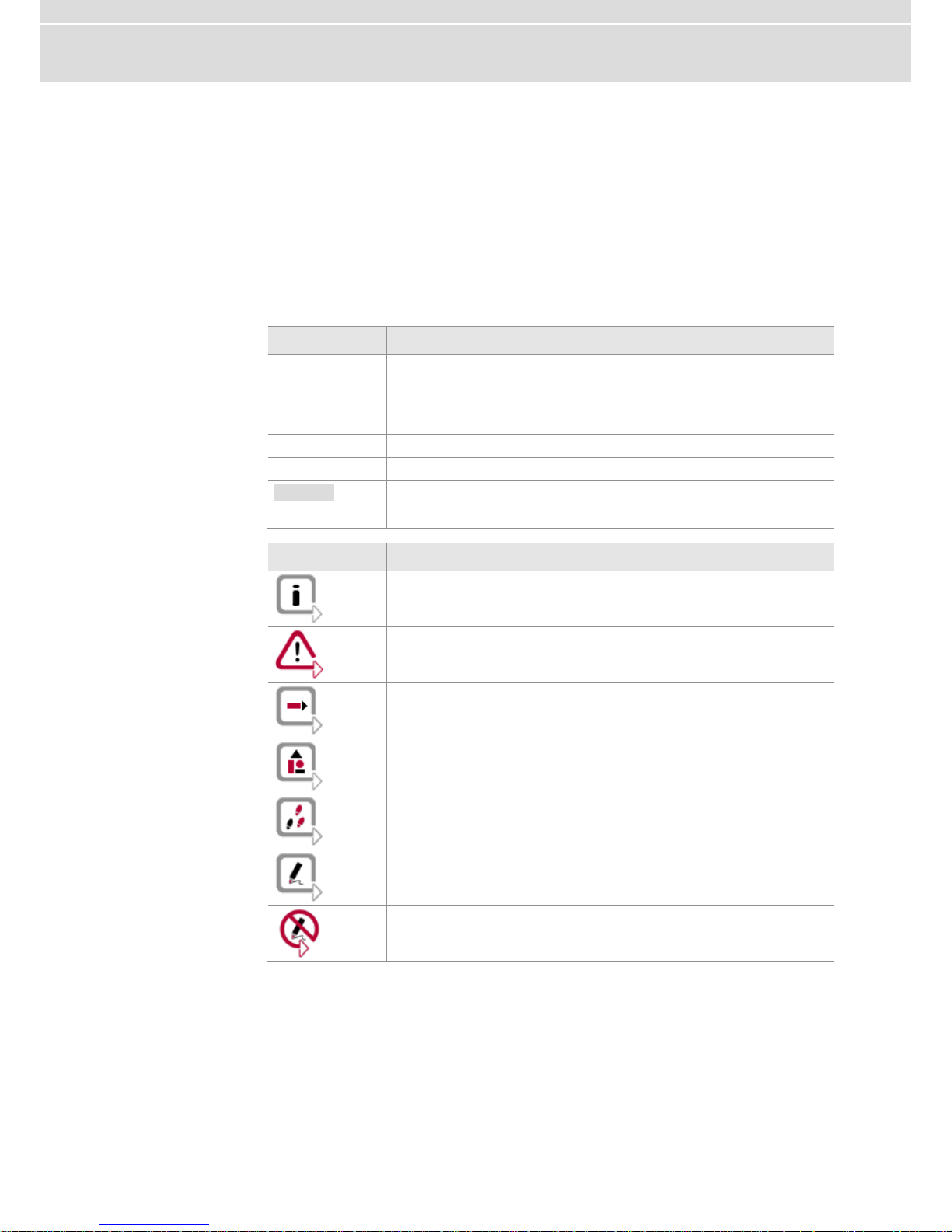
Conventions
In the two following charts you will find the conventions used in the user manual
regarding utilized spellings and symbols.
Style
Utilization
bold
Blocks, surface elements, window- and dialog names of the
software. Accentuation of warnings and advices.
[OK] Push buttons in brackets
File|Save Notation for menus and menu entries
Microsoft
Legally protected proper names and side notes.
Source Code
File name and source code.
Hyperlink
Hyperlinks and references.
<CTRL>+<S>
Notation for shortcuts.
Symbol
Utilization
Here you can obtain supplemental information.
This symbol calls your attention to warnings.
Here you can find additional information.
Here is an example that has been prepared for you.
Step-by-step instructions provide assistance at these points.
Instructions on editing files are found at these points.
This symbol warns you not to edit the specified file.

Manual Introduction
© Vector Informatik GmbH Version 4.0 - 5 -
1.1.1 Certification
Certified Quality
Management System
Vector Informatik GmbH has ISO 9001:2008 certification. The ISO standard is a
globally recognized standard.
1.1.2 Warranty
Restriction of
warranty
We reserve the right to change the contents of the documentation and the software
without notice. Vector Informatik GmbH assumes no liability for correct contents or
damages which are resulted from the usage of the documentation. We are grateful for
references to mistakes or for suggestions for improvement to be able to offer you
even more efficient products in the future.
1.1.3 Support
You need support?
Please check the addresses at the end of this manual for your local support.
1.1.4 Registered trademarks
Registered
trademarks
All trademarks mentioned in this documentation and if necessary third party
registered are absolutely subject to the conditions of each valid label right and the
rights of particular registered proprietor. All trademarks, trade names or company
names are or can be trademarks or registered trademarks of their particular
proprietors. All rights which are not expressly allowed are reserved. If an explicit label
of trademarks, which are used in this documentation, fails, should not mean that a
name is free of third party rights.
Windows, Windows XP, Windows Vista, Windows 7 are trademarks of the
Microsoft Corporation.

Manual CANboardXL Interface Family
© Vector Informatik GmbH Version 4.0 - 7 -
2 CANboardXL Interface Family
In this chapter you find the following information:
2.1 Introduction page 8
2.2 Driver Installation page 8
2.3 Synchronization page 9
Software Sync
Hardware Sync
2.4 Technical Data page 11
CANboardXL Interface Family Manual
- 8 - Version 4.0 © Vector Informatik GmbH
2.1 Introduction
CANboardXL for
PCI, PCIe und PXI
The CANboardXL is available in three variants that have identical functionalities
PCI card for installation in desktop PCs
PCI express card for installation in desktop PCs
Compact PCI/PXI backplane card for installation in industrial PCs
All cards contain a powerful 32 bit 64MHz microcontroller from ATMEL with ARM7
core and two SJA1000 CAN controllers from Philips. The SJA1000 handles CAN
messages with 11 bit as well as 29 bit identifiers. The reception and analysis of
remote frames is possible without restrictions. The CANboardXL is able to detect and
to generate error frames on the bus.
Configuration
The CANboardXL interface family can be configured with the Vector Hardware
Config tool (Windows | Start | Settings | Control Panel | Vector Hardware).
Further details about the tool can be found in the separate installation instructions at
the end of this manual.
Bus types
Various transceivers are available to interface the CANboardXL to a particular type of
bus. These CAN and LIN transceivers are available as plug-in boards (Piggybacks)
and can be mounted on the CANboardXL. For information on installing transceivers
please refer to chapter Replacing Piggybacks on page 15. A list of available
Piggybacks is included in the accessories manual on the driver CD:
\Documentation\Accessories_for_Network_Interfaces.pdf
Connectors
The CANboardXL has the following connectors:
Two D-SUB9 connectors for independent CAN and LIN operation
Binder connector (type 712) for synchronization
Internal sync connector (CANboardXL PCIe only)
Note: The pin assignments of the D-SUB9 connectors depend on the Piggybacks
being used. Further information can be found in the accessories manual on the driver
CD.
2.2 Driver Installation
Note: Information about the driver installation process can be found in the separate
installation instructions at the end of this manual.
Manual CANboardXL Interface Family
© Vector Informatik GmbH Version 4.0 - 9 -
2.3 Synchronization
General information
Time stamps, which are created during a measurement by two or more devices of the
Vector interface family, can be synchronized by software or hardware.
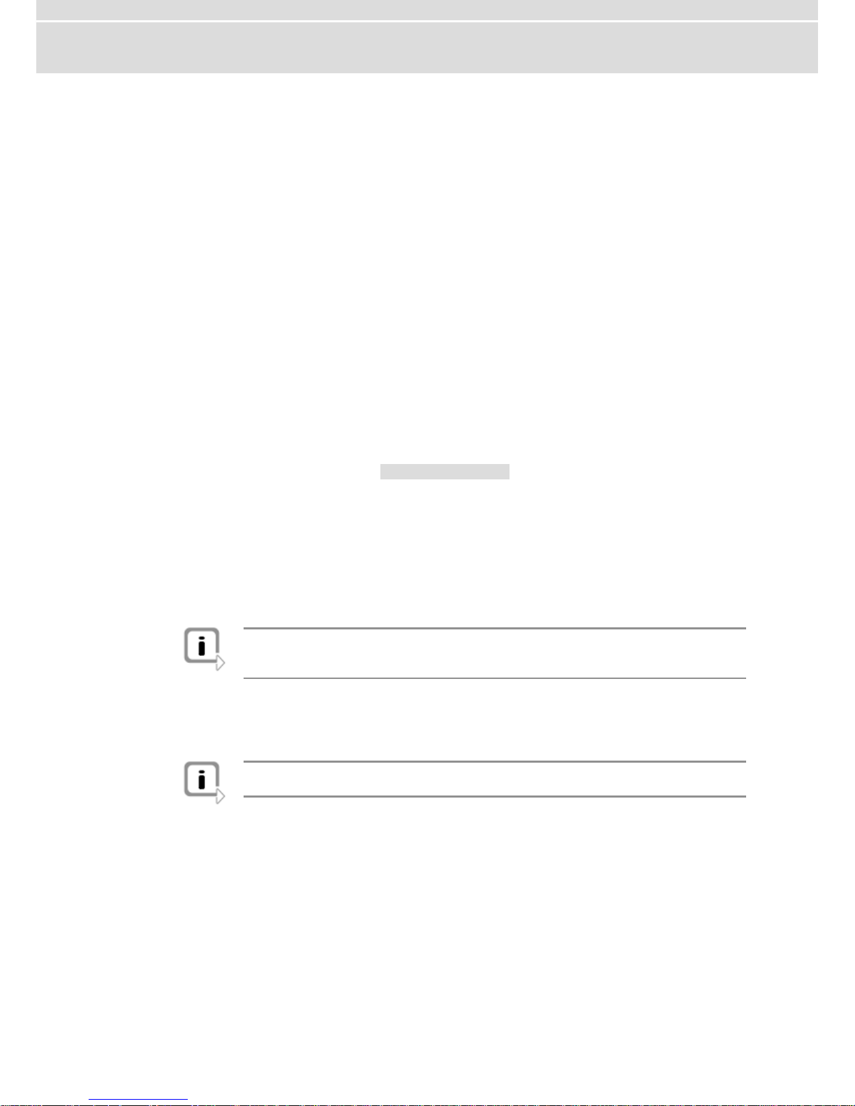
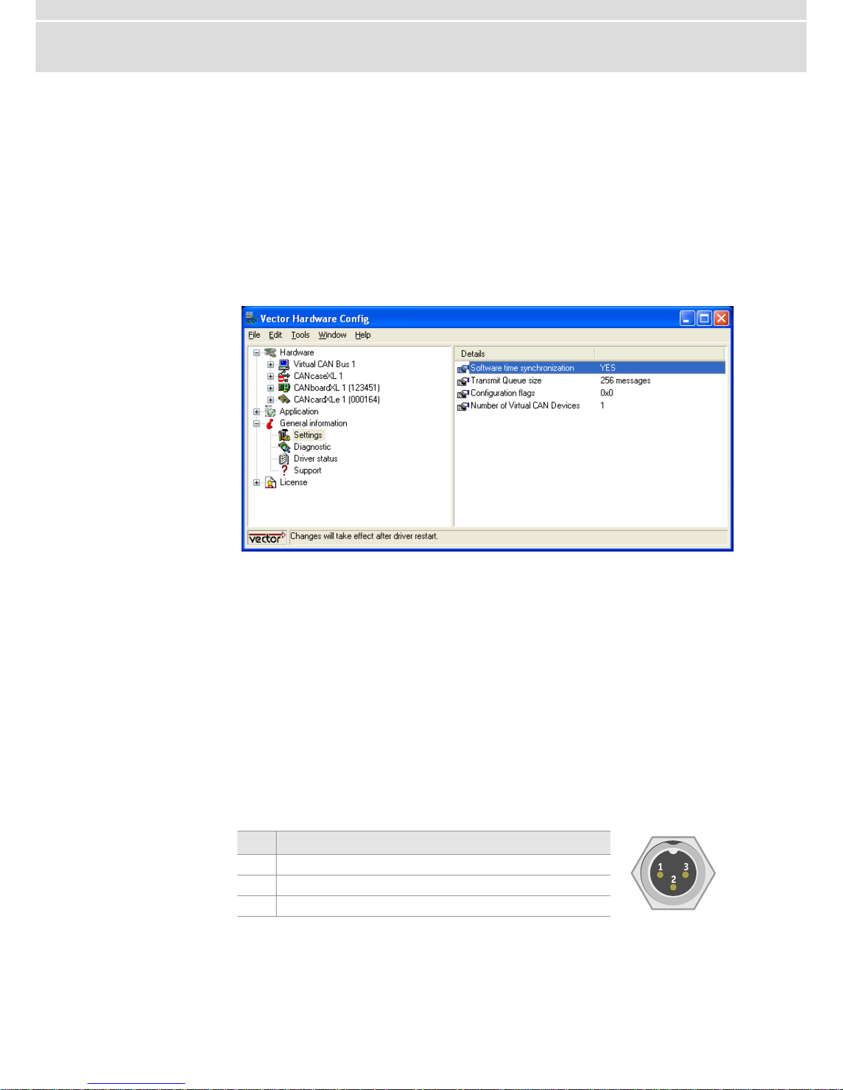
2.3.1 Software Sync
Synchronization
by software
The software synchronization is driver-based and available for all applications without
any restrictions. This kind of synchronization can be switched on in Vector Hardware
Config | General information | Settings | Software time synchronization.
Figure 1: Switching on the software synchronization.
The accuracy of the time stamp correction depends on the device and is typically
50 µs.
2.3.2 Hardware Sync
Synchronization
by hardware
A more precise synchronization of multiple devices is possible via the hardware
synchronization. The hardware synchronization with a maximum of four devices is
done with the SYNCcableXL (see accessories manual, article number 05018) and
has to be supported by the application. The accuracy of the time stamp correction
depends on the application and is typically 1 µs.
Functionality of
the hardware
synchronization
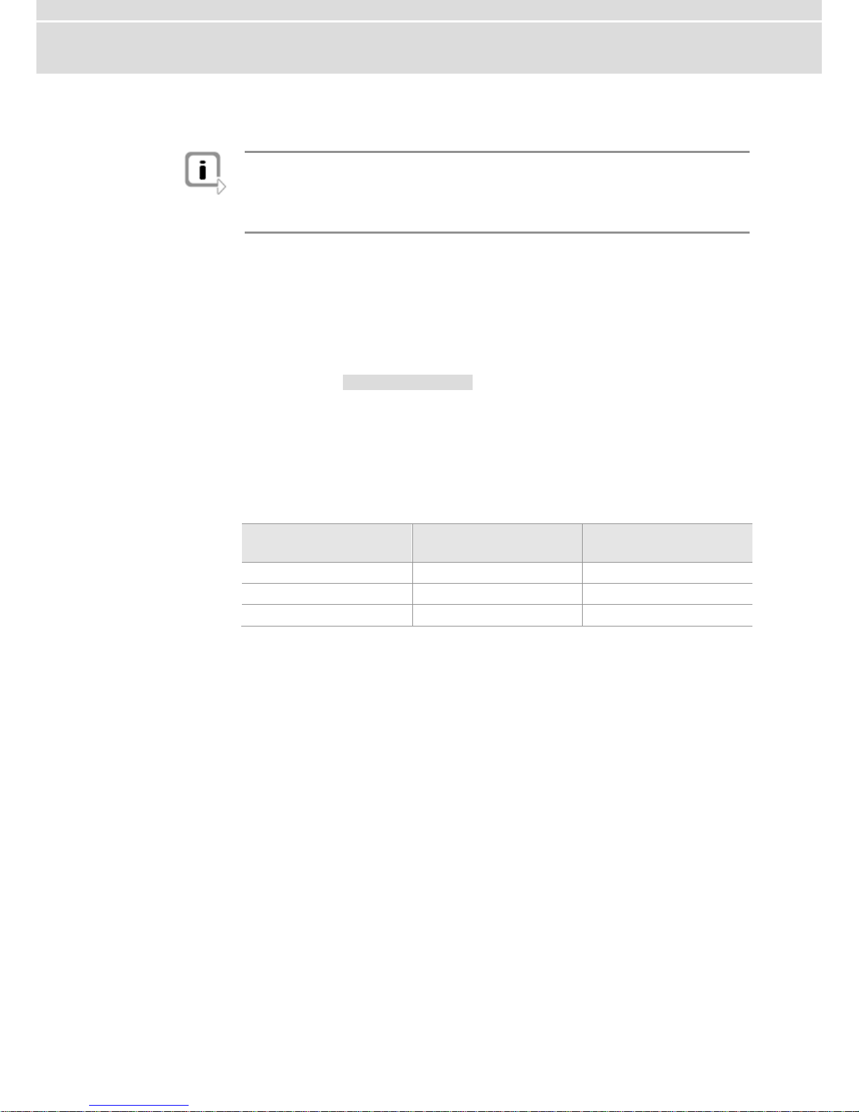
The devices to be synchronized must be interconnected by a two-wire bus (signals:
SYNC and GND). The devices have a 3-pin connector for this use case (Binder type
712).
Pin
Assignment
1
Not connected
2
Synchronization line
3
Ground
At each high-low edge of the sync line the CANboardXL generates a time stamp that
is provided to the application. This allows the application to synchronize the time
stamps of different devices to a common time base.
CANboardXL Interface Family Manual
- 10 - Version 4.0 © Vector Informatik GmbH
The synchronization edges can be generated by the VN or the XL interface family.
Note: The hardware synchronization must be supported by the application. For
further information please refer to the relevant manual. Please note that the software
synchronization must be disabled (see Vector Hardware Config | General
information | Settings | Software time synchronization) if the hardware
synchronization is used.
Synchronization by
sync connector
(CANboardXL PCIe)
Multiple CANboardXL PCIe can be synchronized either by the Binder connector
outside the PC housing or by the internal sync connector. The internal sync connector
is a 10-pin connector (90° offset) and available next to the Piggyback slots. The
synchronization is done with a ribbon cable and a 10-pin standard socket.
Time synchronization
through
PXI backplane
Additional to the synchronization described above, the CANboardXL pxi supports time
synchronization through the PXI backplane.
In Figure 3 (see Replacing Piggybacks on page 15) you can see the switches (white
circle) that are used to control the synchronization between the cards.
In position ON, the synchronization is active. The right and left end of the
synchronization line, which is build with multiple CANboardXL pxi cards, has to be cut
off. The cut off of the right end is done with switch 2, the cut off of the left end with
switch 1.
Example
Time synchronization with three CANboardXL pxi:
CANboardXL pxi
Switch 1
Switch 2
1 (left)
OFF
ON
2 (middle)
ON
ON
3 (right)
ON
OFF
Manual CANboardXL Interface Family
© Vector Informatik GmbH Version 4.0 - 11 -
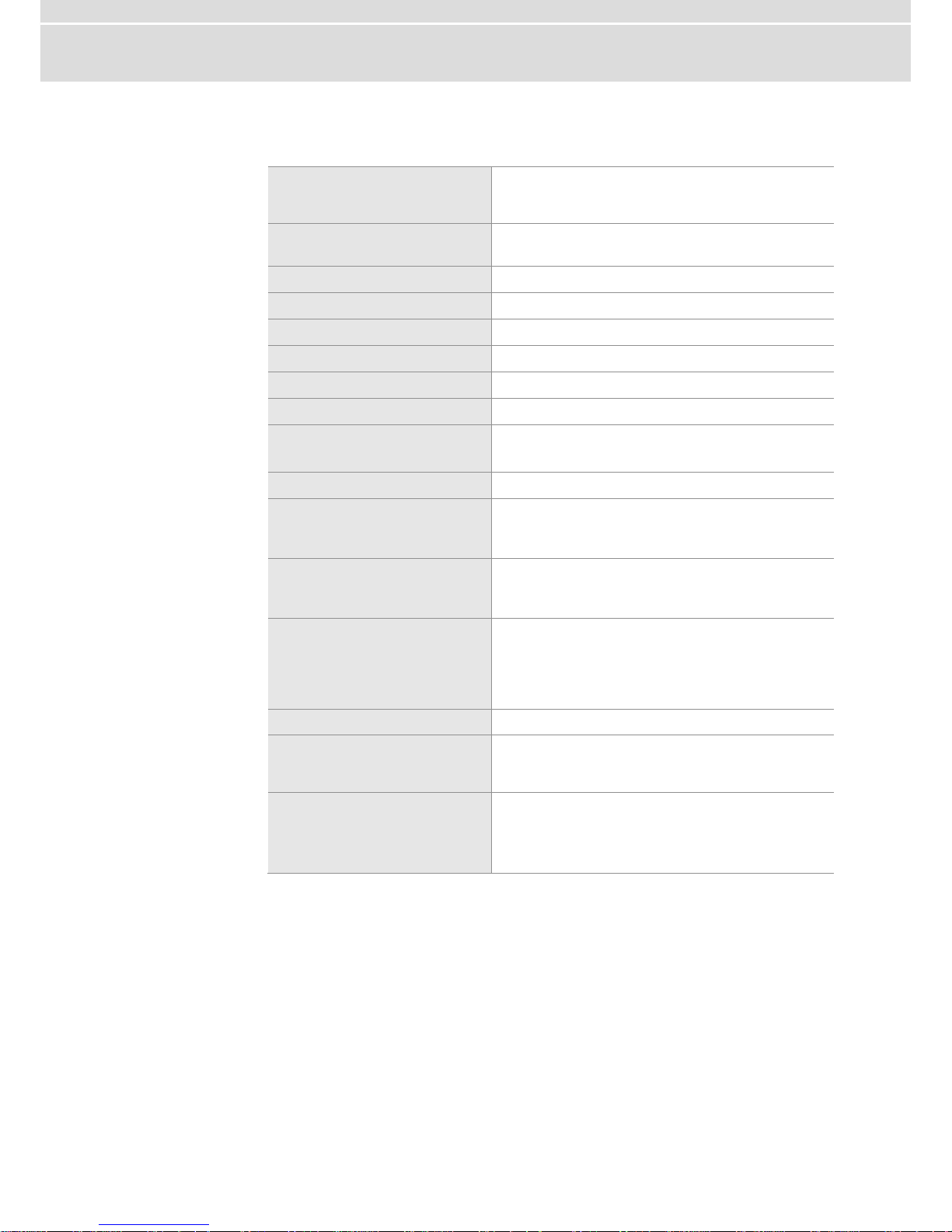
2.4 Technical Data
PC interface
CANboardXL : PCI
CANboardXL PCIe : PCI Express
CANboardXL pxi : Compact PCI / PXI
Channels
2 independent channels
for CAN, LIN and J1708
Transceiver
Piggybacks
CAN controller
2 Phillips SJA 1000
Microcontroller
ATMEL AT91R40008 32bit 64MHz
Max. baudrate
1 Mbit/s
Time stamp accuracy
1 µs
Error frame
Detection and generation
Power consumption
1W for CANboardXL/pxi without Piggybacks
2,5W for CANboardXL PCIe without Piggybacks
Configuration
Plug & Play
Dimensions
approx. 155 x 135 x 20 mm (PCI)
approx. 145 x 105 x 17 mm (PCIe)
approx. 210 x 135 x 20 mm (pxi)
Weight
approx. 210 g without Piggybacks (PCI)
approx. 210 g without Piggybacks (PCIe)
approx. 350 g without Piggybacks (pxi)
Temperature range
Operation: Standard -20...65 °C (PCI)
Operation: Standard 0...65 °C (PCIe)
Operation: Standard -20...75 °C (pxi)
Transport and storage: -40... 85 °C
Relative humidity
15 %...95 %, not condensing
Software requirements
Windows XP (SP3)
Windows Vista (SP1)
Windows 7
Hardware requirements
IBM PC AT or 100 % compatible;
Free PCI Slot (CANboardXL)
Free PCIe Slot (CANboardXL PCIe)
Free Compact PCI Slot (CANboardXL pxi)

Manual Hardware Installation
© Vector Informatik GmbH Version 4.0 - 13 -
3 Hardware Installation
In this chapter you find the following information:
3.1 General Notes page 14
3.2 CANboardXL and CANboardXL PCIe page 14
3.3 CANboardXL pxi page 14
3.4 Replacing Piggybacks page 15
 Loading...