

Page 1
Manual
CANboardXL Interface Family
Version 4.0
English
Page 2

Imprint
Vector Informatik GmbH
Ingersheimer Straße 24
D-70499 Stuttgart
The information and data given in this user manual can be changed without prior notice. No part of this manual may be reproduced in
any form or by any means without the written permission of the publisher, regardless of which method or which instruments, electronic
or mechanical, are used. All technical information, drafts, etc. are liable to law of copyright protection.
Copyright 2012, Vector Informatik GmbH. Printed in Germany.
All rights reserved.
Art. 80088
Page 3

Manual Table of contents
© Vector Informatik GmbH Version 4.0 - I -
Table of contents
1 Introduction 3
1.1 About this User Manual 4
1.1.1 Certification 5
1.1.2 Warranty 5
1.1.3 Support 5
1.1.4 Registered trademarks 5
2 CANboardXL Interface Family 7
2.1 Introduction 8
2.2 Driver Installation 8
2.3 Synchronization 9
2.3.1 Software Sync 9
2.3.2 Hardware Sync 9
2.4 Technical Data 11
3 Hardware Installation 13
3.1 General Notes 14
3.2 CANboardXL and CANboardXL PCIe 14
3.3 CANboardXL pxi 14
3.4 Replacing Piggybacks 15
4 CANboardXL Accessories 17
4.1 Accessories 18
5 Appendix A: Addresses 19
Page 4

Page 5

Manual Introduction
© Vector Informatik GmbH Version 4.0 - 3 -
1 Introduction
In this chapter you find the following information:
1.1 About this User Manual page 4
Certification
Warranty
Support
Registered trademarks
Page 6
Introduction Manual
- 4 - Version 4.0 © Vector Informatik GmbH
1.1 About this User Manual
To Find information
quickly
This user manual provides you with the following access help:
At the beginning of each chapter you will find a summary of the contents
In the header you can see in which chapter and paragraph you are
Conventions
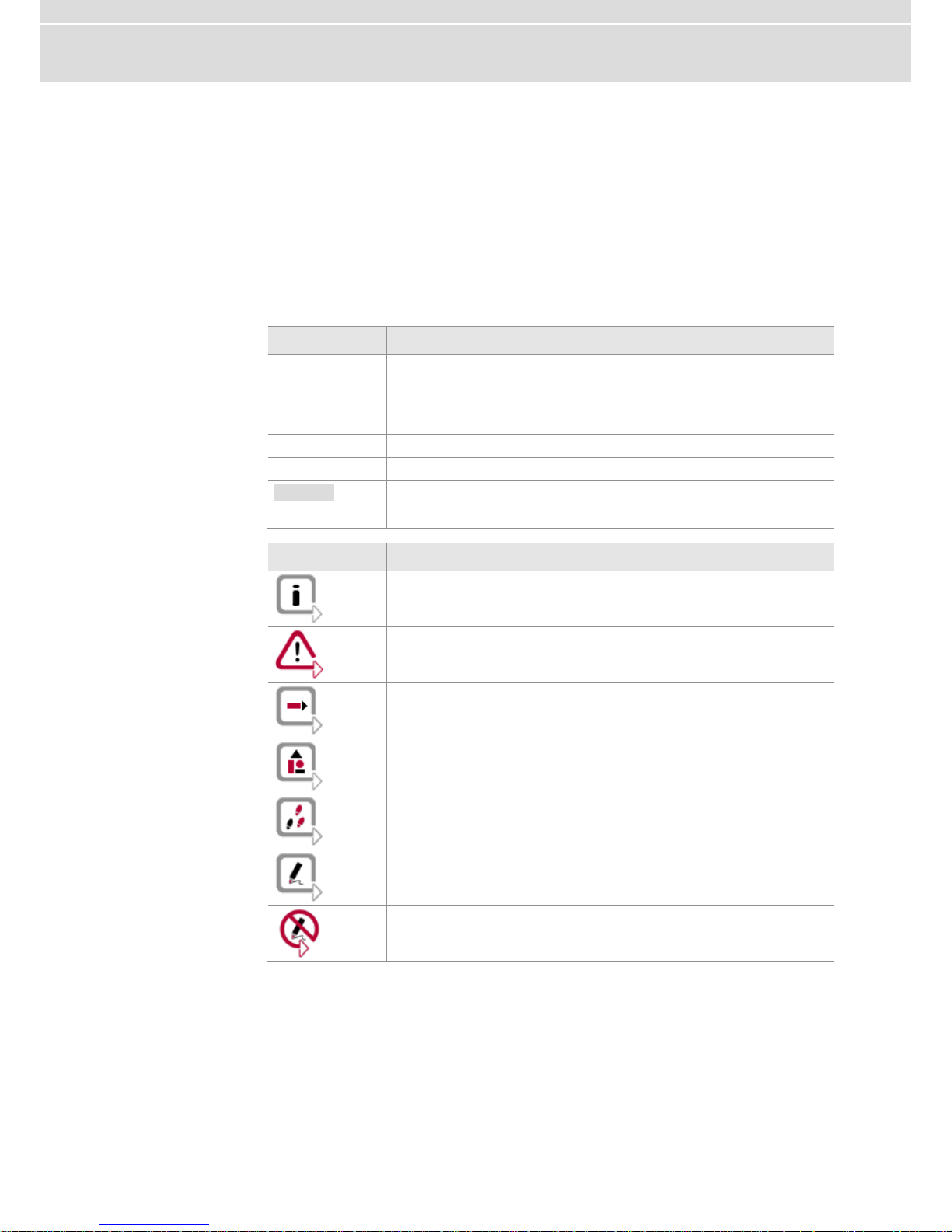
In the two following charts you will find the conventions used in the user manual
regarding utilized spellings and symbols.
Style
Utilization
bold
Blocks, surface elements, window- and dialog names of the
software. Accentuation of warnings and advices.
[OK] Push buttons in brackets
File|Save Notation for menus and menu entries
Microsoft
Legally protected proper names and side notes.
Source Code
File name and source code.
Hyperlink
Hyperlinks and references.
<CTRL>+<S>
Notation for shortcuts.
Symbol
Utilization
Here you can obtain supplemental information.
This symbol calls your attention to warnings.
Here you can find additional information.
Here is an example that has been prepared for you.
Step-by-step instructions provide assistance at these points.
Instructions on editing files are found at these points.
This symbol warns you not to edit the specified file.
Page 7

Manual Introduction
© Vector Informatik GmbH Version 4.0 - 5 -
1.1.1 Certification
Certified Quality
Management System
Vector Informatik GmbH has ISO 9001:2008 certification. The ISO standard is a
globally recognized standard.
1.1.2 Warranty
Restriction of
warranty
We reserve the right to change the contents of the documentation and the software
without notice. Vector Informatik GmbH assumes no liability for correct contents or
damages which are resulted from the usage of the documentation. We are grateful for
references to mistakes or for suggestions for improvement to be able to offer you
even more efficient products in the future.
1.1.3 Support
You need support?
Please check the addresses at the end of this manual for your local support.
1.1.4 Registered trademarks
Registered
trademarks
All trademarks mentioned in this documentation and if necessary third party
registered are absolutely subject to the conditions of each valid label right and the
rights of particular registered proprietor. All trademarks, trade names or company
names are or can be trademarks or registered trademarks of their particular
proprietors. All rights which are not expressly allowed are reserved. If an explicit label
of trademarks, which are used in this documentation, fails, should not mean that a
name is free of third party rights.
Windows, Windows XP, Windows Vista, Windows 7 are trademarks of the
Microsoft Corporation.
Page 8

Page 9

Manual CANboardXL Interface Family
© Vector Informatik GmbH Version 4.0 - 7 -
2 CANboardXL Interface Family
In this chapter you find the following information:
2.1 Introduction page 8
2.2 Driver Installation page 8
2.3 Synchronization page 9
Software Sync
Hardware Sync
2.4 Technical Data page 11
Page 10
CANboardXL Interface Family Manual
- 8 - Version 4.0 © Vector Informatik GmbH
2.1 Introduction
CANboardXL for
PCI, PCIe und PXI
The CANboardXL is available in three variants that have identical functionalities
PCI card for installation in desktop PCs
PCI express card for installation in desktop PCs
Compact PCI/PXI backplane card for installation in industrial PCs
All cards contain a powerful 32 bit 64MHz microcontroller from ATMEL with ARM7
core and two SJA1000 CAN controllers from Philips. The SJA1000 handles CAN
messages with 11 bit as well as 29 bit identifiers. The reception and analysis of
remote frames is possible without restrictions. The CANboardXL is able to detect and
to generate error frames on the bus.
Configuration
The CANboardXL interface family can be configured with the Vector Hardware
Config tool (Windows | Start | Settings | Control Panel | Vector Hardware).
Further details about the tool can be found in the separate installation instructions at
the end of this manual.
Bus types
Various transceivers are available to interface the CANboardXL to a particular type of
bus. These CAN and LIN transceivers are available as plug-in boards (Piggybacks)
and can be mounted on the CANboardXL. For information on installing transceivers
please refer to chapter Replacing Piggybacks on page 15. A list of available
Piggybacks is included in the accessories manual on the driver CD:
\Documentation\Accessories_for_Network_Interfaces.pdf
Connectors
The CANboardXL has the following connectors:
Two D-SUB9 connectors for independent CAN and LIN operation
Binder connector (type 712) for synchronization
Internal sync connector (CANboardXL PCIe only)
Note: The pin assignments of the D-SUB9 connectors depend on the Piggybacks
being used. Further information can be found in the accessories manual on the driver
CD.
2.2 Driver Installation
Note: Information about the driver installation process can be found in the separate
installation instructions at the end of this manual.
Page 11
Manual CANboardXL Interface Family
© Vector Informatik GmbH Version 4.0 - 9 -
2.3 Synchronization
General information
Time stamps, which are created during a measurement by two or more devices of the
Vector interface family, can be synchronized by software or hardware.
2.3.1 Software Sync
Synchronization
by software
The software synchronization is driver-based and available for all applications without
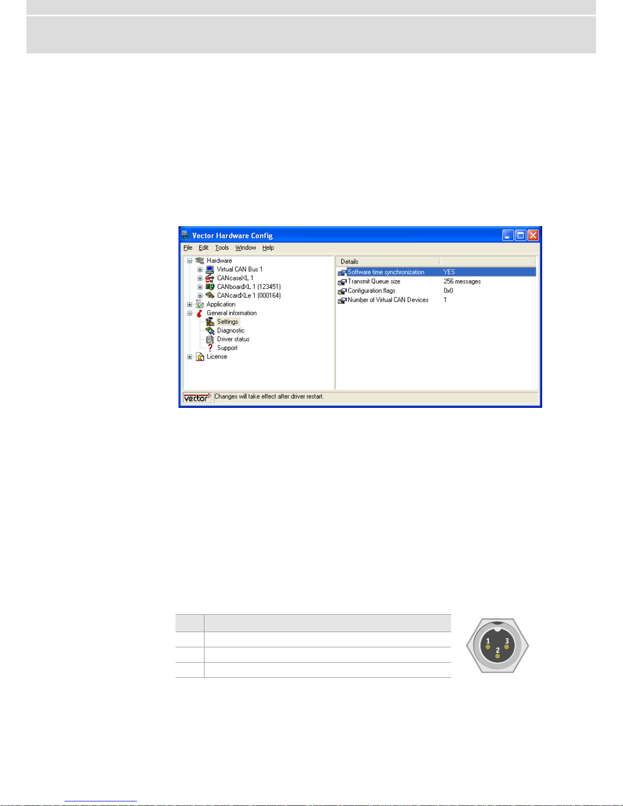
any restrictions. This kind of synchronization can be switched on in Vector Hardware
Config | General information | Settings | Software time synchronization.
Figure 1: Switching on the software synchronization.
The accuracy of the time stamp correction depends on the device and is typically
50 µs.
2.3.2 Hardware Sync
Synchronization
by hardware
A more precise synchronization of multiple devices is possible via the hardware
synchronization. The hardware synchronization with a maximum of four devices is
done with the SYNCcableXL (see accessories manual, article number 05018) and
has to be supported by the application. The accuracy of the time stamp correction
depends on the application and is typically 1 µs.
Functionality of
the hardware
synchronization
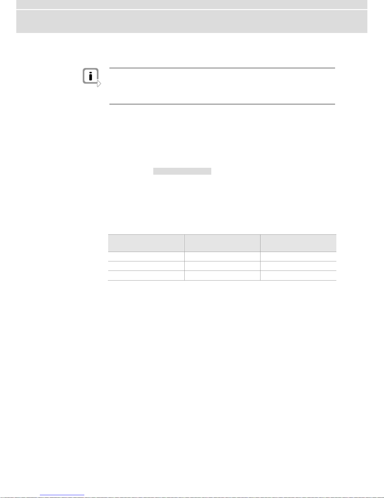
The devices to be synchronized must be interconnected by a two-wire bus (signals:
SYNC and GND). The devices have a 3-pin connector for this use case (Binder type
712).
Pin
Assignment
1
Not connected
2
Synchronization line
3
Ground
At each high-low edge of the sync line the CANboardXL generates a time stamp that
is provided to the application. This allows the application to synchronize the time
stamps of different devices to a common time base.
Page 12
CANboardXL Interface Family Manual
- 10 - Version 4.0 © Vector Informatik GmbH
The synchronization edges can be generated by the VN or the XL interface family.
Note: The hardware synchronization must be supported by the application. For
further information please refer to the relevant manual. Please note that the software
synchronization must be disabled (see Vector Hardware Config | General
information | Settings | Software time synchronization) if the hardware
synchronization is used.
Synchronization by
sync connector
(CANboardXL PCIe)
Multiple CANboardXL PCIe can be synchronized either by the Binder connector
outside the PC housing or by the internal sync connector. The internal sync connector
is a 10-pin connector (90° offset) and available next to the Piggyback slots. The
synchronization is done with a ribbon cable and a 10-pin standard socket.
Time synchronization
through
PXI backplane
Additional to the synchronization described above, the CANboardXL pxi supports time
synchronization through the PXI backplane.
In Figure 3 (see Replacing Piggybacks on page 15) you can see the switches (white
circle) that are used to control the synchronization between the cards.
In position ON, the synchronization is active. The right and left end of the
synchronization line, which is build with multiple CANboardXL pxi cards, has to be cut
off. The cut off of the right end is done with switch 2, the cut off of the left end with
switch 1.
Example
Time synchronization with three CANboardXL pxi:
CANboardXL pxi
Switch 1
Switch 2
1 (left)
OFF
ON
2 (middle)
ON
ON
3 (right)
ON
OFF
Page 13
Manual CANboardXL Interface Family
© Vector Informatik GmbH Version 4.0 - 11 -
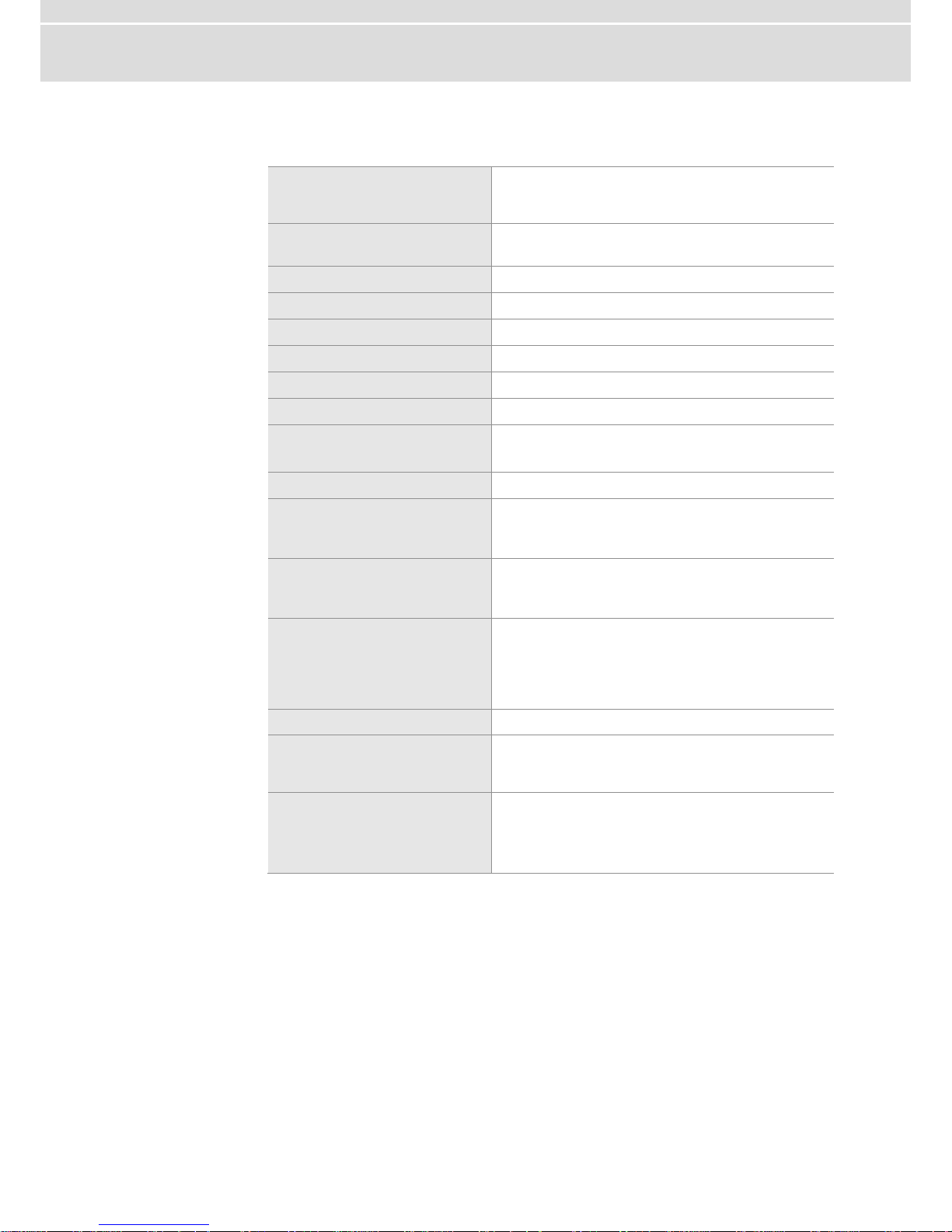
2.4 Technical Data
PC interface
CANboardXL : PCI
CANboardXL PCIe : PCI Express
CANboardXL pxi : Compact PCI / PXI
Channels
2 independent channels
for CAN, LIN and J1708
Transceiver
Piggybacks
CAN controller
2 Phillips SJA 1000
Microcontroller
ATMEL AT91R40008 32bit 64MHz
Max. baudrate
1 Mbit/s
Time stamp accuracy
1 µs
Error frame
Detection and generation
Power consumption
1W for CANboardXL/pxi without Piggybacks
2,5W for CANboardXL PCIe without Piggybacks
Configuration
Plug & Play
Dimensions
approx. 155 x 135 x 20 mm (PCI)
approx. 145 x 105 x 17 mm (PCIe)
approx. 210 x 135 x 20 mm (pxi)
Weight
approx. 210 g without Piggybacks (PCI)
approx. 210 g without Piggybacks (PCIe)
approx. 350 g without Piggybacks (pxi)
Temperature range
Operation: Standard -20...65 °C (PCI)
Operation: Standard 0...65 °C (PCIe)
Operation: Standard -20...75 °C (pxi)
Transport and storage: -40... 85 °C
Relative humidity
15 %...95 %, not condensing
Software requirements
Windows XP (SP3)
Windows Vista (SP1)
Windows 7
Hardware requirements
IBM PC AT or 100 % compatible;
Free PCI Slot (CANboardXL)
Free PCIe Slot (CANboardXL PCIe)
Free Compact PCI Slot (CANboardXL pxi)
Page 14

Page 15

Manual Hardware Installation
© Vector Informatik GmbH Version 4.0 - 13 -
3 Hardware Installation
In this chapter you find the following information:
3.1 General Notes page 14
3.2 CANboardXL and CANboardXL PCIe page 14
3.3 CANboardXL pxi page 14
3.4 Replacing Piggybacks page 15
Page 16

Hardware Installation Manual
- 14 - Version 4.0 © Vector Informatik GmbH
3.1 General Notes
Caution: Turn off the main power supply and disconnect your computer’s power cord.
Otherwise systems using an ATX power supply unit with soft power off may still be
powering the PCI slot. This can damage your PCI card when it is inserted into the slot
Caution: Do not force the CANboardXL into the slot. Make sure that the connectors
of the card’s PCI connector are aligned with the bus connector on the motherboard
before you insert the card into the slot. If it does not fit properly, gently remove it and
try again.
Note: Please observe all safety precautions prescribed by your PC manufacturer for
card installation!
Note: Do not touch the bottom and the topside of the PCBs (CANboardXL main
board and Piggybacks).
3.2 CANboardXL and CANboardXL PCIe
1. Turn off the computer and all peripheral devices. Unplug the power cord and
open the case.
2. Touch a metal plate on your computer to ground yourself and to discharge any
static electricity.
3. Remove the metal brackets from an unused slot.
4. Align the CANboardXL with the PCI/PCIe slot and press the card gently but firmly
into the slot.
5. Replace the computer cover.
6. Plug in the power cord.
3.3 CANboardXL pxi
1. Turn off the computer and all peripheral devices. Unplug the power cord and
open the case.
2. Touch a metal plate on your computer to ground yourself and to discharge any
static electricity.
3. Align the CANboardXL pxi with the slot and press the card gently but firmly into
the slot.
4. The CANboardXL pxi has to be fixed again with the screws.
Page 17

Manual Hardware Installation
© Vector Informatik GmbH Version 4.0 - 15 -
3.4 Replacing Piggybacks
1. Unplug the power cord and open the case.
2. Touch a metal plate on your computer to ground yourself and to discharge any
static electricity.
3. Unplug the CANboardXL.
Note: Each of the Piggybacks is fixed with a screw.
4. Detach the screw with the screw protection and remove the Piggyback carefully.
5. Plug in the alternative Piggyback.
CANboardXL
Figure 2: Channel 1 and 2 on CANboardXL.
CANboardXL pxi
Ch 1
Ch 2
Figure 3: Channel 1 and 2 on CANboardXL pxi.
Info: The two-row connector and the one-row connector must fit and must not be
displaced laterally.
Page 18

Hardware Installation Manual
- 16 - Version 4.0 © Vector Informatik GmbH
6. The Piggyback has to be fixed again with the screw and the screw protection.
7. Firmly insert the card into the selected slot. Push down to ensure the card is fully
seated.
8. Replace the computer cover.
9. Plug in the power cord.
Page 19

Manual CANboardXL Accessories
© Vector Informatik GmbH Version 4.0 - 17 -
4 CANboardXL Accessories
In this chapter you find the following information:
4.1 Accessories page 18
Page 20

CANboardXL Accessories Manual
- 18 - Version 4.0 © Vector Informatik GmbH
4.1 Accessories
Reference: Further information about the available accessories can be found in the
separate accessories manual on the driver CD:
\Documentation\Accessories_for_Network_Interfaces.pdf
Page 21

Manual Appendix A: Addresses
© Vector Informatik GmbH Version 4.0 - 19 -
5 Appendix A: Addresses
Vector Informatik
GmbH
Vector Informatik GmbH
Ingersheimer Str. 24
70499 Stuttgart
Germany
Support: +49 711 80670-200
Phone: +49 711 80670-0
Fax: +49 711 80670-111
mailto:info@de.vector.com
http://www.vector.com
Vector CANtech, Inc.
Vector CANtech, Inc.
39500 Orchard Hill Place
Suite 550
Novi, Mi 48375
USA
Support: +1 248 449 9290 Option 2
Phone: +1 248 449 9290
Fax: +1 248 449 9704
mailto:info@us.vector.com
http://www.vector.com
Vector Automotive
Technology
(Shanghai) Co., Ltd.
Vector Automotive Technology (Shanghai) Co., Ltd.
Sunyoung Center
Room 1701, No.398 Jiangsu Road
Changning District
Shanghai 200050
China
Phone: +86 21 6432 53530
Fax: +86 21 6432 5308
mailto:info@cn.vector.com
http://www.vector.com
Vector France SAS
Vector France SAS
168, Boulevard Camélinat
92240 Malakoff
France
Support: +33 1 4231 4010
Phone: +33 1 4231 4000
Fax: +33 1 4231 4009
mailto:information@fr.vector.com
http://www.vector.com
Page 22

Appendix A: Addresses Manual
- 20 - Version 4.0 © Vector Informatik GmbH
Vector GB Ltd.
Vector GB Ltd.
Rhodium
Central Boulevard
Blythe Valley Park
Solihull, Birmingham
West Midlands B90 8AS
United Kingdom
Support: +44 121 50681-77
Phone: +44 121 50681-50
mailto:info@uk.vector.com
http://www.vector.com
Vector Informatik
India Pvt. Ltd.
Vector Informatik India Pvt. Ltd.
Lokesh Madan
4/1/1/1, Sutar Icon, Sus Road
Pashan, Pune - 411 021
India
Phone: +91 20 2587 2023
Fax: +91 20 2587 2025
mailto:info@in.vector.com
http://www.vector.com
Vector Japan Co.,
Ltd.
Vector Japan Co., Ltd.
Seafort Square Center Bld.
18F, 2-3-12,
Higashi-shinagawa, Shinagawa-ku
Tokyo 140-0002
Japan
Support: +81 3 5769 7800
Phone: +81 3 5769 7800
Fax: +81 3 5769 6975
mailto:info@jp.vector.com
http://www.vector.com
Vector Korea IT Inc.
Vector Korea IT Inc.
#1406 Mario Tower
222-12 Guro-dong, Guro-gu
Seoul, 152-848
Republic of Korea
Support: : +82 2 807 0600 Ext.2
Phone: +82 2 807 0600
Fax: +82 2 8070601
mailto:info@kr.vector.com
http://www.vector.com
Page 23

Manual
© Vector Informatik GmbH Version 4.0 - 21 -
VecScan AB
VecScan AB
Theres Svenssons Gata 9
417 55 Göteborg
Sweden
Support: +46 (31) 764 76-00
Phone: +46 (31) 76476-00
Fax: +46 (31) 76476-19
mailto:info@se.vector.com
http://www.vector.com
Page 24

Page 25

Manual
Installation Instructions
Version 3.0
English
Page 26

Imprint
Vector Informatik GmbH
Ingersheimer Straße 24
D-70499 Stuttgart
The information and data given in this user manual can be changed without prior notice. No part of this manual may be reproduced in
any form or by any means without the written permission of the publisher, regardless of which method or which instruments, electronic
or mechanical, are used. All technical information, drafts, etc. are liable to law of copyright protection.
Copyright 2012, Vector Informatik GmbH. Printed in Germany.
All rights reserved.
Page 27

Manual Table of contents
© Vector Informatik GmbH Version 3.0 - I -
Table of contents
1 Introduction 3
1.1 About this User Manual 4
1.1.1 Certification 5
1.1.2 Warranty 5
1.1.3 Support 5
1.1.4 Registered Trademarks 5
2 Driver Installation 7
2.1 Minimum Requirements 8
2.2 Hints 8
2.3 Vector Driver Setup 9
2.4 Vector Hardware Configuration 11
3 Operating Test 13
3.1 Loop Test 14
3.1.1 CAN 14
3.1.2 FlexRay 16
3.1.3 MOST 17
4 Appendix A: Addresses 19
Page 28

Page 29

Manual Introduction
© Vector Informatik GmbH Version 3.0 - 3 -
1 Introduction
In this chapter you find the following information:
1.1 About this User Manual page 4
Certification
Warranty
Support
Registered Trademarks
Page 30

Introduction Manual
- 4 - Version 3.0 © Vector Informatik GmbH
1.1 About this User Manual
To find information
quickly
This user manual provides you with the following access help:
At the beginning of each chapter you will find a summary of the contents
In the header you can see in which chapter and paragraph you are
Conventions
In the two following charts you will find the conventions used in the user manual
regarding utilized spellings and symbols.
Style
Utilization
bold
Blocks, surface elements, window- and dialog names of the
software. Accentuation of warnings and advices.
[OK] Push buttons in brackets
File|Save Notation for menus and menu entries
Microsoft
Legally protected proper names and side notes.
Source Code
File name and source code.
Hyperlink
Hyperlinks and references.
<CTRL>+<S>
Notation for shortcuts.
Symbol
Utilization
Here you can obtain supplemental information.
This symbol calls your attention to warnings.
Here you can find additional information.
Here is an example that has been prepared for you.
Step-by-step instructions provide assistance at these points.
Instructions on editing files are found at these points.
This symbol warns you not to edit the specified file.
Page 31

Manual Introduction
© Vector Informatik GmbH Version 3.0 - 5 -
1.1.1 Certification
Certified Quality
Management System
Vector Informatik GmbH has ISO 9001:2008 certification. The ISO standard is a
globally recognized standard.
1.1.2 Warranty
Restriction
of warranty
We reserve the right to change the contents of the documentation and the software
without notice. Vector Informatik GmbH assumes no liability for correct contents or
damages which are resulted from the usage of the documentation. We are grateful for
references to mistakes or for suggestions for improvement to be able to offer you
even more efficient products in the future.
1.1.3 Support
You need support?
Please check the addresses at the end of this manual for your local support.
1.1.4 Registered Trademarks
Registered
trademarks
All trademarks mentioned in this documentation and if necessary third party
registered are absolutely subject to the conditions of each valid label right and the
rights of particular registered proprietor. All trademarks, trade names or company
names are or can be trademarks or registered trademarks of their particular
proprietors. All rights which are not expressly allowed are reserved. If an explicit label
of trademarks, which are used in this documentation, fails, should not mean that a
name is free of third party rights.
Windows, Windows XP, Windows Vista, Windows 7 are trademarks of the
Microsoft Corporation.
Page 32

Page 33

Manual Driver Installation
© Vector Informatik GmbH Version 3.0 - 7 -
2 Driver Installation
In this chapter you find the following information:
2.1 Minimum Requirements page 8
2.3 Vector Driver Setup page 9
2.4 Vector Hardware Configuration page 11
Page 34

Driver Installation Manual
- 8 - Version 3.0 © Vector Informatik GmbH
2.1 Minimum Requirements
Hardware
CPU
Pentium 4 or higher
Memory
512 MB or more
Network interface
CANcardXL : PCMCIA
CANcardXLe : ExpressCard 54
CANboardXL PCI : PCI
CANboardXL PCIe : PCI Express 1x
CANboardXL PXI : Compact PCI/PXI
CANcaseXL : USB
CANcaseXL log : USB
VN1610 : USB
VN1611 : USB
VN1630 : USB
VN2610 : USB
VN2640 : USB
VN3300 : PCI
VN3600 : USB
VN7600 : USB
VN8910 : USB
Software
Operating system
Windows XP SP3 (32 bit)
Windows Vista SP1 (32 bit)
Windows 7 (32/64 bit)
Driver version
8.x
Measurement
application
The devices can be run with several applications from Vector
(e. g. CANoe, CANalyzer) or with measurement applications
from other companies. Therefor the devices require a related
license. Applications based on the Vector XL Driver Library can
be run without a license.
2.2 Hints
Note: Many desktop PCs have power managers which block the CPU for a specific
time. This impairs accuracy of the time system. If your application has stringent timing
requirements (e. g. time-driven sending of messages or time-driven evaluations), you
have to deactivate these power managers. Power management settings may be con-
tained in the BIOS setup or on the Control Panel of Windows XP / Vista / Windows 7
(e. g. Power options).
No further mention will be made of the power manager in this document.
Info: Please note that you will need Administrator Rights for the following steps.
Page 35

Manual Driver Installation
© Vector Informatik GmbH Version 3.0 - 9 -
2.3 Vector Driver Setup
General information
The Vector Driver Disk offers a driver setup which allows the installation or the
removal of Vector devices.
1. Execute the driver setup from the autostart menu or directly from
\Drivers\Setup.exe before the device is inserted or connected to the PC with
the included USB cable.
If you have already inserted or connected the device to the PC, the Windows
found new Hardware wizard appears. Close this wizard and then execute the
driver setup.
2. Click [Next] in the driver setup dialog. The initialization process starts.
Page 36

Driver Installation Manual
- 10 - Version 3.0 © Vector Informatik GmbH
3. In the driver selection dialog select your devices to be installed (or to be
uninstalled).
4. Click [Install] to execute the driver installation, or [Uninstall] to remove existing
drivers.
5. A confirmation dialog appears. Click [Close] to exit.
If the driver has been properly installed, the device can be inserted or connected
to the PC with the included USB cable. The device is ready for operation now.
6. For Windows XP users only:
If the Windows found new Hardware wizard appears, select the option for auto-
matic driver search to complete the installation.
Page 37

Manual Driver Installation
© Vector Informatik GmbH Version 3.0 - 11 -
2.4 Vector Hardware Configuration
Executing Vector
Hardware Config
After the successful installation you will find the configuration application Vector
Hardware in the Control Panel (see below). The tool gives you information about the
connected and installed Vector devices. There are also several settings that can be
changed.
Control panel
Windows XP
Category view
Start | (Settings) | Control Panel, click in the left part of the window for further
Control Panel options followed by Vector Hardware.
Classic view
Start | (Settings) | Control Panel, click Vector Hardware in the list.
Control panel
Windows Vista
Category view
Start | (Settings) | Control Panel, click in the right part of the window for
Additional Options followed by Vector Hardware.
Classic view
Start | (Settings) | Control Panel, click Vector Hardware in the list.
Control panel
Windows 7
Category view
Start | Control Panel | Hardware and Sound, click Vector Hardware in the list.
Symbols view
Start | Control Panel, click Vector Hardware in the list.
The tool is split into two windows. The left window lets you access the installed Vector
devices, the right window displays the details of the selection. The following nodes
are available in the left window:
Hardware
Each installed Vector device is shown in Hardware. Additional details of available
channels are shown in a tree view. Status information on the device components and
the channels are also shown in this dialog.
Page 38

Driver Installation Manual
- 12 - Version 3.0 © Vector Informatik GmbH
Application
In Application all available applications are shown with their configured channels. If
you click on an application, all of its channels are displayed in the right pane on the
screen.
General information
The General information section contains general information on Vector devices and
applications.
License
The License section contains information on all currently valid licenses.
Note: You will find a detailed description of Vector Hardware Config in the online
help (Help | Contents).
Page 39

Manual Operating Test
© Vector Informatik GmbH Version 3.0 - 13 -
3 Operating Test
In this chapter you find the following information:
3.1 Loop Test page 14
CAN
FlexRay
MOST
Page 40

Operating Test Manual
- 14 - Version 3.0 © Vector Informatik GmbH
3.1 Loop Test
Operating test
The test described here can be performed to check the functional integrity of the
driver and the device. This test is identical for Windows XP, Windows Vista,
Windows 7 and independent of the application being used.
3.1.1 CAN
Device test
The operating test for CAN can be executed with the following devices:
CANcardXL
CANcardXLe
CANcaseXL
CANcaseXL log
CANboardXL Family
VN1610
VN1630
VN7600
Loop3.exe
Either two High-Speed or two Low-Speed transceivers are necessary for this
functional test:
1. Connect two CAN channels with a suitable cable. If two High-Speed transceivers
are being used, we recommend our CANcable 1 (CANcable 0 for Low-Speed
transceivers).
2. Start \Drivers\Common\Loop3.exe from the driver CD.
This program accesses the Vector devices and transmits CAN messages.
3. Select the connected CAN channels of the device(s) to be tested.
4. Set the appropriate baudrate depending on the transceiver being used (HighSpeed max. 1,000,000 Bd, Low-Speed max. 125,000 Bd).
5. Click [Start].
Page 41

Manual Operating Test
© Vector Informatik GmbH Version 3.0 - 15 -
6. You will see statistical data in the lower part of the window if the system has been
configured properly.
Loop3 application
7. The test procedure can be terminated with the [Stop] button.
An OK should appear in the upper part of the window.
Page 42

Operating Test Manual
- 16 - Version 3.0 © Vector Informatik GmbH
3.1.2 FlexRay
Device test
The operating test for FlexRay can be executed with the following devices:
VN3300
VN3600
VN7600
FRLoop.exe
This operating test requires an inserted FRpiggy.
1. Remove the FlexRay cable if it is connected.
2. Start \Drivers\Common\FRLoop.exe from the driver CD.
3. Execute the test.
4. If no error messages occur, the operating test was successful.
Page 43

Manual Operating Test
© Vector Informatik GmbH Version 3.0 - 17 -
3.1.3 MOST
Device test
The operating test for MOST can be executed with the following devices:
VN2610
VN2640
MLoop.exe
This functional test requires a MOST fiber optic cable and a fiber coupler for HFBR
connectors.
1. VN2610
Start \Drivers\Common\MLoop.exe from the driver CD
VN2640
Start \Drivers\Common\M150Loop.exe from the driver CD.
2. Select the VN2610/VN2640 to be tested from the list of detected devices.
3. Click [Twinkle] and check if the power LED of the VN2610/VN2640 is blinking at
least for one second.
4. Connect the MOST fiber optic cable with the VN2610/VN2640 device, select
Master mode and check if the program displays the status Unlock. Check if red
light comes out of the Tx fiber of the MOST fiber optic cable.
5. Connect both ends of the fiber with one fiber coupler to a ring and check if the
program displays the status Lock.
6. Close MLoop.exe with [Exit].
Page 44

Page 45

Manual Appendix A: Addresses
© Vector Informatik GmbH Version 3.0 - 19 -
4 Appendix A: Addresses
Vector Informatik
GmbH
Vector Informatik GmbH
Ingersheimer Str. 24
70499 Stuttgart
Germany
Support: +49 711 80670-200
Phone: +49 711 80670-0
Fax: +49 711 80670-111
mailto:info@de.vector.com
http://www.vector.com
Vector CANtech, Inc.
Vector CANtech, Inc.
39500 Orchard Hill Place
Suite 550
Novi, Mi 48375
USA
Support: +1 248 449 9290 Option 2
Phone: +1 248 449 9290
Fax: +1 248 449 9704
mailto:info@us.vector.com
http://www.vector.com
Vector Automotive
Technology
(Shanghai) Co., Ltd.
Vector Automotive Technology (Shanghai) Co., Ltd.
Sunyoung Center
Room 1701, No.398 Jiangsu Road
Changning District
Shanghai 200050
China
Phone: +86 21 6432 53530
Fax: +86 21 6432 5308
mailto:info@cn.vector.com
http://www.vector.com
Vector France SAS
Vector France SAS
168, Boulevard Camélinat
92240 Malakoff
France
Support: +33 1 4231 4010
Phone: +33 1 4231 4000
Fax: +33 1 4231 4009
mailto:information@fr.vector.com
http://www.vector.com
Page 46

Appendix A: Addresses Manual
- 20 - Version 3.0 © Vector Informatik GmbH
Vector GB Ltd.
Vector GB Ltd.
Rhodium
Central Boulevard
Blythe Valley Park
Solihull, Birmingham
West Midlands B90 8AS
United Kingdom
Support: +44 121 50681-77
Phone: +44 121 50681-50
mailto:info@uk.vector.com
http://www.vector.com
Vector Informatik
India Pvt. Ltd.
Vector Informatik India Pvt. Ltd.
Lokesh Madan
4/1/1/1, Sutar Icon, Sus Road
Pashan, Pune - 411 021
India
Phone: +91 20 2587 2023
Fax: +91 20 2587 2025
mailto:info@in.vector.com
http://www.vector.com
Vector Japan Co.,
Ltd.
Vector Japan Co., Ltd.
Seafort Square Center Bld.
18F, 2-3-12,
Higashi-shinagawa, Shinagawa-ku
Tokyo 140-0002
Japan
Support: +81 3 5769 7800
Phone: +81 3 5769 7800
Fax: +81 3 5769 6975
mailto:info@jp.vector.com
http://www.vector.com
Vector Korea IT Inc.
Vector Korea IT Inc.
#1406 Mario Tower
222-12 Guro-dong, Guro-gu
Seoul, 152-848
Republic of Korea
Support: : +82 2 807 0600 Ext.2
Phone: +82 2 807 0600
Fax: +82 2 8070601
mailto:info@kr.vector.com
http://www.vector.com
Page 47

Manual Appendix A: Addresses
© Vector Informatik GmbH Version 3.0 - 21 -
VecScan AB
VecScan AB
Theres Svenssons Gata 9
417 55 Göteborg
Sweden
Support: +46 (31) 764 76-00
Phone: +46 (31) 76476-00
Fax: +46 (31) 76476-19
mailto:info@se.vector.com
http://www.vector.com
Page 48

Get more Information!
Visit our Website for:
> News
> Products
> Demo Software
> Support
> Training Classes
> Addresses
www.vector.com
 Loading...