

Page 1

BRICK THUNDER DOCK
BRICK
THUNDER DOCK
Manual
Version 1.0
Page 2

Imprint
Vector Informatik GmbH
Ingersheimer Straße 24
D-70499 Stuttgart
The information and data given in this user manual can be changed without prior notice. No part of this
manual may be reproduced in any form or by any means without the written permission of the
publisher, regardless of which method or which instruments, electronic or mechanical, are used. All
technical information, drafts, etc. are liable to law of copyright protection.
© Copyright 2019, Vector Informatik GmbH. All rights reserved.
Page 3

Contents
1 General Information .......................................................................................................................... 5
Important Instructions .............................................................................................................. 5
Warranty and Liability .............................................................................................................. 5
Trademarks .............................................................................................................................. 6
Used Symbols and their Meanings .......................................................................................... 6
2 Safety ............................................................................................................................................... 7
Proper Use and Intended Purpose .......................................................................................... 7
Hazards ................................................................................................................................... 7
Battery Notice .......................................................................................................................... 7
Electrostatically Sensitive Components (ESD) ........................................................................ 8
Grounding Practices ............................................................................................................ 8
Warning of Hot Surface ........................................................................................................... 8
Disclaimer ................................................................................................................................ 8
3 Product Identification ........................................................................................................................ 9
Scope of Delivery..................................................................................................................... 9
Type Plate ................................................................................................................................ 9
4 Functional Description .................................................................................................................... 10
Overview ................................................................................................................................ 10
5 Technical Specification ................................................................................................................... 10
Base Specification ................................................................................................................. 10
6 Product Description ........................................................................................................................ 11
BRICK THUNDER DOCK Front View ................................................................................... 11
BRICK THUNDER DOCK Rear View .................................................................................... 11
7 Interfaces, Control Elements and Indicators .................................................................................. 12
Thunderbolt® 2 Interface ....................................................................................................... 12
Power Supply Interface ......................................................................................................... 12
8 Commissioning and Maintenance .................................................................................................. 13
Initial Commissioning ............................................................................................................. 14
Thunderbolt® Bridge Detection ......................................................................................... 15
BRICK STORAGE cartridge Driver Installation ................................................................. 17
BRICK STORAGE cartridge Volume Detection ................................................................ 20
Save BRICK STORAGE cartridge removal ....................................................................... 20
Page 4

List of Figures
Figure 1: BRICK THUNDER DOCK Type plate (example) ..................................................................... 9
Figure 2: BRICK THUNDER DOCK front view ...................................................................................... 11
Figure 3: BRICK THUNDER DOCK rear view ....................................................................................... 11
Figure 4: Thunderbolt® 2 interface ........................................................................................................ 12
Figure 5: Power supply interface ........................................................................................................... 12
Figure 6: BRICK THUNDER DOCK front view ...................................................................................... 14
Figure 7: BRICK THUNDER DOCK power In connector ...................................................................... 14
Figure 8: BRICK THUNDER DOCK Thunderbolt® connector .............................................................. 15
Figure 9: BRICK THUNDER DOCK Power switch ................................................................................ 15
Page 5

1 General Information
1
Important Instructions
Prior to use of the unit it is essential to comply with the following instructions. As stipulated by law, we
are providing important safety information and advice how you can avoid damage to the device and
other fittings.
▪ Connection to the power supply must be carried out with correct polarity. Polarity reversal could
cause irreparable damages.
▪ The correct supply voltage is 12V or 24V DC
▪ Operation of the device is allowed only in circuits with safety low voltage within the admissible limit
values (SELV standard EN60950). This applies to all connections to the unit.
▪ The use of a power supply outside the limits defined above could cause damage or even destruction
of the device.
▪ It is forbidden to directly connect the unit to the 230 V mains voltage!
▪ Please avoid mechanical stresses when the device is installed.
▪ The unit has undergone a comprehensive final check to guarantee that it has left the facility in a
perfect condition. Prior to initial operation, the unit has to be examined for damage caused by
transport or inappropriate storage. If there is any damage to the unit it must not be taken into service.
▪ The unit must not be operated with defective safety equipment or with incorrectly mounted or
inoperable safety/protection devices.
▪ Prior to initial operation, please check the suitability of the unit for the specific application. Please
take special note of the admissible environmental and operating conditions specified in the data
sheet.
▪ Any removal of identification numbers, repair work by yourself or modification of the unit is forbidden.
▪ Prior to initial operation carefully read this user manual containing notes and warnings in order to
ensure safe operation.
▪ Unless specified differently, all technical data apply to an environmental temperature of 25°C. The
specified values are subject to the usual fluctuations.
▪ Stresses due to extreme environmental conditions (e.g. heat or cold) over a longer period of time
may influence reliability. Even under normal conditions of use within the admissible limits service
life may be reduced by permanent operation at the limits. Tolerance of the extreme values is subject
to the usual fluctuations.
Warranty and Liability
We reserve the right to change the contents of the documentation and the software without notice.
Vector Informatik GmbH assumes no liability for correct contents or damages which are resulted from
the usage of the documentation. We are grateful for references to mistakes or for suggestions for
improvement to be able to offer you even more efficient products in the future.
Page 6
Trademarks
All trademarks mentioned in this documentation and if necessary third party registered are absolutely
subject to the conditions of each valid label right and the rights of particular registered proprietor. All
trademarks, trade names or company names are or can be trademarks or registered trademarks of their
particular pro- prietors. All rights which are not expressly allowed are reserved. If an explicit label of
trademarks, which are used in this documentation, fails, should not mean that a name is free of third party
rights.
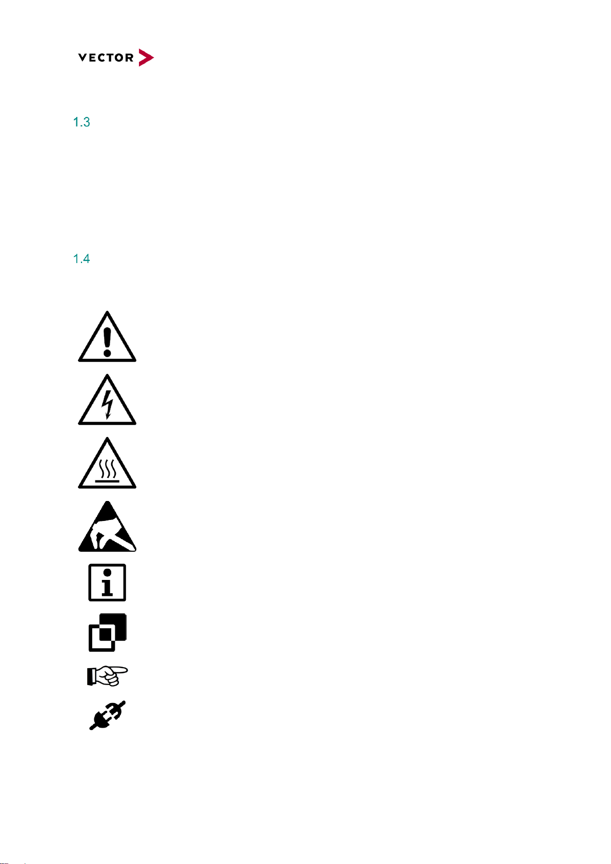
Used Symbols and their Meanings
Symbol
Meaning
Warning of general hazard. The kind of hazard is specified by the text next to the
symbol.
Warning of hazardous electrical voltage and the effects thereof.
This symbol refers to a hot surface that should not be touched without appropriate
precautions. There is danger of burning!
Warning of damages by electrostatic discharge
ESD (Electrostatically Sensitive Device) warning symbol
This symbol refers to general information about device and user manual.
This symbol introduces diverse details as to product configurations.
This symbol indicates that, in the case of non-observance of the warning, the device
or parts thereof could be damaged.
This symbol refers to instructions and recommendations for the connection of external
peripherals and their wiring.
Page 7

2 Safety
In order to avoid personal injuries and damage to property, you have to read and understand the
following safety instructions and hazard warnings prior to installation and use of this hardware. Keep
this documentation (manual) always near the hardware.
Please observe the notes in chapter 1 in addition to this chapter.
Proper Use and Intended Purpose
The hardware may only be operated (i) according to the instructions and descriptions of this manual; (ii)
with the electric power supply designed for the hardware, e.g. USB-powered power supply; and (iii) with
accessories manufactured or approved by Vector.
The hardware is exclusively designed for use by skilled personnel as its operation may result in serious
personal injuries and damage to property. Therefore, only those persons may operate the hardware who
(i) have understood the possible effects of the actions which may be caused by the hardware; (ii) are
specifically trained in the handling with the hardware, bus systems and the system intended to be
influenced; and (iii) have sufficient experience in using the hardware safely.
The knowledge necessary for the operation of the hardware can be acquired in workshops and internal
or external seminars offered by Vector. Additional and hardware specific information, such as „Known
Issues“, are available in the „Vector KnowledgeBase“ on Vector´s website at www.vector.com. Please
consult the „Vector KnowledgeBase“ for updated information prior to the operation of the hardware.
Hazards
The hardware may control and/or otherwise influence the behavior of control systems and electronic
control units. Serious hazards for life, body and property may arise, in particular, without limitation, by
interventions in safety relevant systems (e.g. by deactivating or otherwise manipulating the engine
management, steering, airbag and/or braking system) and/or if the hardware is operated in public areas
(e.g. public traffic, airspace). Therefore, you must always ensure that the hardware is used in a safe
manner. This includes, inter alia, the ability to put the system in which the hardware is used into a safe
state at any time (e.g. by „emergency shutdown“), in particular, without limitation, in the event of errors
or hazards.
Comply with all safety standards and public regulations which are relevant for the operation of the
system. Before you operate the system in public areas, it should be tested on a site which is not
accessible to the public and specifically prepared for performing test drives in order to reduce hazards.
Battery Notice
CAUTION!
There is a risk of explosion if the battery is replaced incorrectly. Replace only with the
same or equivalent type recommended by the manufacturer. Discard used batteries
according to the manufacturer’s instructions.
Please also see the battery supplementary sheet!
Valid only for devices containing a battery.
Page 8

Electrostatically Sensitive Components (ESD)
A sudden electrostatic discharge could destroy sensitive components. Therefore, proper packaging and
grounding prescriptions must be observed. Please always observe the following safety advices.
1. Plug-in cards always have to be transported in electrostatically safe containers or bags.
2. Please leave electrostatically sensitive components in their containers until they have reached the
electrostatically safe assembly site.
3. Take care that you are correctly grounded if you touch electrostatically sensitive components.
4. Make sure that electrostatically sensitive components are stored in protective packages or on
antistatic mats.
Grounding Practices
By observing the following measures, electrostatic damage to the device can be avoided.
1. Lay out antistatic mats at the work place. Wear a grounding strap which is connected to the work
place and the working tools.
2. Use antistatic foot mats, foot grounding equipment or air ionizers to provide additional safety.
3. Only touch sensitive components, plug-in cards and units on the housing or at the outer edges of
the plug-in cards.
4. Avoid contact with pins, wires and conductor tracks.
5. Make sure that all voltage and signal sources are switched off before establishing or disconnecting
electric connections or connecting testing devices.
6. Avoid non-conductive materials such as usual mounting accessories made of plastics or
polystyrene at the work place.
7. Use conductive tools (e.g. ESD screwdrivers) when working on electrostatically sensitive units and
components.
8. Always put plug-in cards and drives on the antistatic mat with the component side downwards.
Warning of Hot Surface
The BRICK THUNDER DOCK System can become very hot during operation and
should not be touched without appropriate precautions. There is danger of burning!
Disclaimer
Claims based on defects and liability claims against Vector are excluded to the extent damages or errors
are caused by improper use of the hardware or use not according to its intended purpose. The same
applies to damages or errors arising from insufficient training or lack of experience of personnel using
the hardware.
Page 9

3 Product Identification
Scope of Delivery
Please check the scope of delivery according to the survey printed below.
Product
BRICK THUNDER DOCK
Accessories
USB Stick (Driver and Documentations)
Thunderbolt® Cable 1m
Power Supply 12V/230V up to 60W, 12V5.0A, only use the specified power supply
Documentation
Manual BRICK THUNDER DOCK (on USB Stick)
Safety supplement
Type Plate
Figure 1: BRICK THUNDER DOCK Type plate
(example)
A type plate like this is located on the bottom of the
device. The example data used here refer to the
BRICK THUNDER DOCK, a device of the BRICK
CORE COM product group.
Symbol
Meaning
Legal notice regarding the disposal of used appliances (WEEE)
CE Label
Page 10

4 Functional Description
Overview
The BRICK THUNDER DOCK is designed to connect a BRICK STORAGE cartridge over a
Thunderbolt® interface to a PC-System.
5 Technical Specification
Base Specification
Basic technical characteristics:
Features
Details
Supply voltage
12V DC 5A
Storage interface
BRICK STORAGE cartridge
PC interface
Thunderbolt® 2
Housing dimensions
320 x 44 x 250 (B x H x T) mm
Cooling
Active
Weight
approx. 3kg
Characteristics
Details
Operating temperature device
0°C to +40°C
Storage temperature device
-40°C to +75°C
Air humidity
90% non-condensing
IP protection class
IP20
Electromagnetic compatibility (EMC)
EMV Directive 2014/30/EU
Safety
LVD Directive 2014/35/EU (Power Supply 230V)
RoHS II directive
2011/65/EU
Certifications
FCC Industrial Class A
Page 11

6 Product Description
BRICK THUNDER DOCK Front View
Figure 2: BRICK THUNDER DOCK front view
Pos.
Designation
Description
1 BRICK STORAGE cartridge slot
2 Air outlet, do not cover
BRICK THUNDER DOCK Rear View
Figure 3: BRICK THUNDER DOCK rear view
Pos.
Designation
Description
1
Thunderbolt IF
Thunderbolt 2 connector
2 Air inlet
3 Power LED
4 Power switch
5
POWER IN
Power input supply connector, only use the specified power supply
❸
❹
❺
❶
❷
❶
❷
Page 12

7 Interfaces, Control Elements and Indicators
Thunderbolt® 2 Interface
This connector provides the Thunderbolt® 2 interface (redundant ports).
Thunderbolt® 2 interface
Figure 4: Thunderbolt® 2 interface
Power Supply Interface
LED
Signal
LED Array
1
Power LED
Figure 5: Power supply interface
2
Power Switch
3
Power supply connector
2,1x5,5mm
❶ ❷ ❸
Page 13

8 Commissioning and Maintenance
In order to avoid injuries and damage caused by direct or indirect contact with hot surfaces the
following instructions must be observed:
Die BRICK THUNDER DOCK must be positioned and installed in a maintenance area or in an
operating facility of limited access.
The users having permission to enter the maintenance area or the operating facility must have
received adequate instructions regarding the risks.
Important instructions!
For positioning and installation or removal of the BRICK THUNDER DOCK System, please
observe the relevant instructions given in this user manual.
The device must only be positioned and installed by maintenance personnel responsible in this
area (that is familiar with the associated risks).
The device can be operated in all positions except with the upper side downwards.
In order to avoid overheating of the platform, keep a distance of at least 100 mm to the upper
cooling fins of the chassis.
In case of installation in a housing (e.g. a control cabinet): The housing (control cabinet) must
have enough space for the BRICK THUNDER DOCK System and the corresponding spaces
for air circulation and cable connections. Moreover, the housing must have sufficient, possibly
active, ventilation to avoid overheating.
The cooling fins and the inlet and discharge openings of the housing must not be blocked
(covered).
Page 14

Initial Commissioning
The accessories of the BRICK THUNDER DOCK include an appropriate power supply, a Thunderbolt®
cable and Windows® OS drivers.
1. Prerequisites
a. This Docking Station only works with Thunderbolt® aware Personal Computers.
b. Be sure the BRICK THUNDER DOCK is switched off
2. Insert a BRICK STORAGE cartridge (is not part of the scope of delivery) into the BRICK THUNDER
DOCK Docking Station.
Figure 6: BRICK THUNDER DOCK front view
3. Connect the Power supply line to the power supply unit and to the rear side (1) of the BRICK
THUNDER DOCK.
Figure 7: BRICK THUNDER DOCK power In connector
❶
Page 15

4. Connect the Thunderbolt® cable to the PC and to one of the two Thunderbolt® connectors on the
rear side (2) of the BRICK THUNDER DOCK. The second connector could be used to “Daisy chain”
2 BRICK THUNDER DOCK Stations (not specified).
Figure 8: BRICK THUNDER DOCK Thunderbolt® connector
5. If the PC is not powered, switch on the PC
6. Switch on (3) the BRICK THUNDER DOCK and see if the green LED (4) is on.
Figure 9: BRICK THUNDER DOCK Power switch
Thunderbolt® Bridge Detection
The following message of a Thunderbolt® aware Windows® system appears:
Proceed with the ok button and you get the next window where you have to define if the connection
should be accepted automatically.
❸
❷
❹
Page 16

Please choose “connect always”
Please accept the Thunderbolt® Device in the next message box:
Now the Thunderbolt® Bridge is installed and the RAID Controller within in the BRICK STORAGE
cartridge is detected by the system.
Page 17

BRICK STORAGE cartridge Driver Installation
If the system does not automatically ask you for a “RAID Controller” driver please use the devicemanager to update/install the driver:
Choose the correct driver directory on the accessory USB stick:
Press Install to install to device driver
Page 18

After correct installation procedure you get this message:
In Device Manager you will see the RAID controller now in category “Storage Controllers”.
Page 19

Page 20

BRICK STORAGE cartridge Volume Detection
After a successful driver installation procedure, you also should get a volume mounted by the OS.
Save BRICK STORAGE cartridge removal
If you want to disconnect the BRICK STORAGE cartridge form your PC system please use the
appropriate OS function:
Choose the “disconnect” icon:
Choose the correct volume to disconnect:
The system informs you, when the BRCK STORAGE cartridge can be removed and BRICK
THUNDER DOCK can be switched off.
 Loading...