

Page 1
BRICK CORE COM
Manual
Version 2.0n
Page 2

Imprint
Vector Informatik GmbH
Ingersheimer Straße 24
D-70499 Stuttgart
The information and data given in this user manual can be changed without prior notice. No part of this
manual may be reproduced in any form or by any means without the written permission of the
publisher, regardless of which method or which instruments, electronic or mechanical, are used. All
technical information, drafts, etc. are liable to law of copyright protection.
© Copyright 2019, Vector Informatik GmbH. All rights reserved.
Page 3

Contents
1 General Information ..................................................................................................................... 6
Important instructions .............................................................................................................. 6
Warranty and liability ............................................................................................................... 6
Trademarks .............................................................................................................................. 7
Used symbols and their meanings .......................................................................................... 7
2 Safety ........................................................................................................................................... 8
Proper Use and Intended Purpose .......................................................................................... 8
Hazards ................................................................................................................................... 8
Battery notice ........................................................................................................................... 8
Electrostatically Sensitive Components (ESD) ........................................................................ 9
Grounding practices............................................................................................................. 9
Warning of hot surface ............................................................................................................ 9
Disclaimer ................................................................................................................................ 9
3 System Configuration ................................................................................................................ 10
BRICK CORE COM computer core ....................................................................................... 11
Add-On BRICK CORE COM STORAGE BAY ...................................................................... 12
Add-On BRICK CORE COM PCIe ........................................................................................ 12
4 BRICK STORAGE ..................................................................................................................... 13
Lock / Unlock BRICK STORAGE cartridge ........................................................................... 13
BRICK STORAGE cartridge order Information ..................................................................... 13
5 Accessories ............................................................................................................................... 14
6 Product Identification ................................................................................................................. 15
Scope of delivery ................................................................................................................... 15
Type Plate .............................................................................................................................. 15
7 Technical Specification .............................................................................................................. 16
Technical Characteristics of BRICK CORE COM: ................................................................ 16
Environmental Characteristics and Conformity ..................................................................... 17
BRICK Temperature Management ........................................................................................ 17
BRICK System Critical Temperature warnings (absolute maximum rates) ....................... 17
BRICK STORAGE cartridge temperature warnings .......................................................... 18
Mechanical Details: ............................................................................................................... 19
BRICK CORE COM ........................................................................................................... 19
BRICK CORE COM with STORAGE BAY Add-on ............................................................ 20
BRICK CORE COM with STORAGE BAY and PCIe Add-ons .......................................... 21
8 Product Description ................................................................................................................... 22
BRICK CORE COM Computer Core ..................................................................................... 22
Front side BRICK CORE COM Computer core ................................................................. 22
Rear side BRICK CORE COM Computer core ................................................................. 23
BRICK CORE COM with STORAGE BAY ............................................................................ 24
Front side BRICK CORE COM with STORAGE BAY ....................................................... 24
9 Interfaces, Control Elements and Indicators ............................................................................. 25
Page 4

1GbE/TS 1/2/3/4 .................................................................................................................... 25
10GbE 1/2 .............................................................................................................................. 26
USB Client ............................................................................................................................. 26
DP (DisplayPort) .................................................................................................................... 27
2x Serial ATA (SATA) Port .................................................................................................... 28
USB3.0 Port 1/2/3/4 ............................................................................................................... 29
1GbE MGMT Port .................................................................................................................. 29
HMI Power ............................................................................................................................. 30
HMI Power button and LEDs ................................................................................................. 30
GPS SMA/F ........................................................................................................................... 31
SMA Port OPT1/2 .................................................................................................................. 31
SMA-RP WLAN 1/2 ............................................................................................................... 31
Microphone Input ................................................................................................................... 32
Headphones Output .............................................................................................................. 33
1GbE/802.1AS ....................................................................................................................... 34
CFast Slot .............................................................................................................................. 35
SYSCTRL (internal System Control) ..................................................................................... 36
GPIO General Purpose I/Os .................................................................................................. 37
Electrical characteristics Input/Output ........................................................................... 37
10 Typical Installation ..................................................................................................................... 38
Vehicle Power Wiring Diagram BRICK CORE COM and UPS (for reference only) .............. 38
11 BIOS/UEFI BRICK CORE COM 5700EQP616G ...................................................................... 39
Determination of the BIOS version ........................................................................................ 39
Operation ............................................................................................................................... 39
Advanced HDD Configuration ................................................................................... 40
Advanced South Bridge Configuration ...................................................................... 41
Advanced Onboard UART & CPLD Configuration .................................................... 42
12 Commissioning and Maintenance ............................................................................................. 43
Initial commissioning ............................................................................................................. 44
BRICK Core COM 5700EQP6 Operating system ......................................................... 46
Handling of internal components ........................................................................................... 47
Page 5

List of Figures
Figure 1: BRICK CORE COMplus ......................................................................................................... 11
Figure 2: BRICK CORE COMplus including STORAGE BAY attachment frame ................................. 12
Figure 3: BRICK CORE COMplus including STORAGE BAY and PCIe Add-on .................................. 12
Figure 4: BRICK CORE COM type plate (example) .............................................................................. 15
Figure 5: BRICK CORE COM mechanical drawing............................................................................... 19
Figure 6: BRICK CORE COM with STORAGE BAY mechanical drawing ............................................ 20
Figure 7: BRICK CORE COM with STORAGE BAY and PCIe mechanical drawing ............................ 21
Figure 8: BRICK CORE COMplus front view connectors ...................................................................... 22
Figure 9: BRICK CORE COMplus rear view connectors ...................................................................... 23
Figure 10: BRICK CORE COMplus front view STORAGE BAY connectors ......................................... 24
Figure 11: BRICK CORE COM STORAGE insert ................................................................................. 24
Figure 12: Pin assignment 1GbE/TS ..................................................................................................... 25
Figure 13: Pin assignment 10GbE/TS ................................................................................................... 26
Figure 14: Pin assignment USB Client .................................................................................................. 26
Figure 15: Pin assignment DisplayPort ................................................................................................. 27
Figure 16: Pin assignment mini SAS x4 ................................................................................................ 28
Figure 17: Pin assignment USB3.0 1/2/3/4 ........................................................................................... 29
Figure 18: Pin assignment 1GbE MGMT .............................................................................................. 29
Figure 19: Pin assignment HMI PWR .................................................................................................... 30
Figure 20: HMI Power button and LEDs ................................................................................................ 30
Figure 21: Pin assignment GPS ............................................................................................................ 31
Figure 22: Pin assignment OPT1/2 ....................................................................................................... 31
Figure 23: Pin assignment WLAN 1/2 ................................................................................................... 31
Figure 24: Pin assignment microphone ................................................................................................. 32
Figure 25: Pin assignment headphones ................................................................................................ 33
Figure 26: Pin assignment 1GbE 802.1AS ............................................................................................ 34
Figure 27: Pin assignment CFast .......................................................................................................... 35
Figure 28: Pin assignment SYSCTRL ................................................................................................... 36
Figure 29: Pin assignment GPIOs ......................................................................................................... 37
Figure 30: Power Wiring Diagram BRICK CORE COM and BRICK UPS ............................................. 38
Page 6

1 General Information
Important instructions
Prior to use of the unit it is essential to comply with the following instructions. As stipulated by law, we
are providing important safety information and advice how you can avoid damage to the device and
other fittings.
▪ Connection to the power supply must be carried out with correct polarity. Polarity reversal could
cause irreparable damages.
▪ The correct supply voltage is 12V or 24V DC
▪ Operation of the device is allowed only in circuits with safety low voltage within the admissible limit
values (SELV standard EN60950). This applies to all connections to the unit.
▪ The use of a power supply outside the limits defined above could cause damage or even destruction
of the device.
▪ It is forbidden to directly connect the unit to the 230 V mains voltage!
▪ Please avoid mechanical stresses when the device is installed.
▪ The unit has undergone a comprehensive final check to guarantee that it has left the facility in a
perfect condition. Prior to initial operation, the unit has to be examined for damage caused by
transport or inappropriate storage. If there is any damage to the unit it must not be taken into service.
▪ The unit must not be operated with defective safety equipment or with incorrectly mounted or
inoperable safety/protection devices.
▪ Prior to initial operation, please check the suitability of the unit for the specific application. Please
take special note of the admissible environmental and operating conditions specified in the data
sheet.
▪ Any removal of identification numbers, repair work by yourself or modification of the unit is forbidden.
▪ Prior to initial operation carefully read this user manual containing notes and warnings in order to
ensure safe operation.
▪ Unless specified differently, all technical data apply to an environmental temperature of 25°C. The
specified values are subject to the usual fluctuations.
▪ Stresses due to extreme environmental conditions (e.g. heat or cold) over a longer period of time
may influence reliability. Even under normal conditions of use within the admissible limits service
life may be reduced by permanent operation at the limits. Tolerance of the extreme values is subject
to the usual fluctuations.
Warranty and liability
We reserve the right to change the contents of the documentation and the software without notice.
Vector Informatik GmbH assumes no liability for correct contents or damages which are resulted from
the usage of the documentation. We are grateful for references to mistakes or for suggestions for
improvement to be able to offer you even more efficient products in the future.
Page 7
Trademarks
All trademarks mentioned in this documentation and if necessary third party registered are absolutely
subject to the conditions of each valid label right and the rights of particular registered proprietor. All
trademarks, trade names or company names are or can be trademarks or registered trademarks of their
particular pro- prietors. All rights which are not expressly allowed are reserved. If an explicit label of
trademarks, which are used in this documentation, fails, should not mean that a name is free of third party
rights.
Used symbols and their meanings
Symbol
Meaning
Warning of general hazard. The kind of hazard is specified by the text next to the
symbol.
Warning of hazardous electrical voltage and the effects thereof.
This symbol refers to a hot surface that should not be touched without appropriate
precautions. There is danger of burning!
Warning of damages by electrostatic discharge
ESD (Electrostatically Sensitive Device) warning symbol
This symbol refers to general information about device and user manual.
This symbol introduces diverse details as to product configurations.
This symbol indicates that, in the case of non-observance of the warning, the device
or parts thereof could be damaged.
This symbol refers to instructions and recommendations for the connection of external
peripherals and their wiring.
Page 8

2 Safety
In order to avoid personal injuries and damage to property, you have to read and understand the
following safety instructions and hazard warnings prior to installation and use of this hardware. Keep
this documentation (manual) always near the hardware.
Please observe the notes in chapter 1.1 in addition to this chapter.
Proper Use and Intended Purpose
The hardware may only be operated (i) according to the instructions and descriptions of this manual; (ii)
with the electric power supply designed for the hardware, e.g. USB-powered power supply; and (iii) with
accessories manufactured or approved by Vector.
The hardware is exclusively designed for use by skilled personnel as its operation may result in serious
personal injuries and damage to property. Therefore, only those persons may operate the hardware who
(i) have understood the possible effects of the actions which may be caused by the hardware; (ii) are
specifically trained in the handling with the hardware, bus systems and the system intended to be
influenced; and (iii) have sufficient experience in using the hardware safely.
The knowledge necessary for the operation of the hardware can be acquired in workshops and internal
or external seminars offered by Vector. Additional and hardware specific information, such as „Known
Issues“, are available in the „Vector KnowledgeBase“ on Vector´s website at www.vector.com. Please
consult the „Vector KnowledgeBase“ for updated information prior to the operation of the hardware.
Hazards
The hardware may control and/or otherwise influence the behavior of control systems and electronic
control units. Serious hazards for life, body and property may arise, in particular, without limitation, by
interventions in safety relevant systems (e.g. by deactivating or otherwise manipulating the engine
management, steering, airbag and/or braking system) and/or if the hardware is operated in public areas
(e.g. public traffic, airspace). Therefore, you must always ensure that the hardware is used in a safe
manner. This includes, inter alia, the ability to put the system in which the hardware is used into a safe
state at any time (e.g. by „emergency shutdown“), in particular, without limitation, in the event of errors
or hazards.
Comply with all safety standards and public regulations which are relevant for the operation of the
system. Before you operate the system in public areas, it should be tested on a site which is not
accessible to the public and specifically prepared for performing test drives in order to reduce hazards.
Battery notice
CAUTION!
There is a risk of explosion if the battery is replaced incorrectly. Replace only with the
same or equivalent type recommended by the manufacturer. Discard used batteries
according to the manufacturer’s instructions.
Please also see the battery supplementary sheet!
Valid only for devices containing a battery.
Page 9

Electrostatically Sensitive Components (ESD)
A sudden electrostatic discharge could destroy sensitive components. Therefore, proper packaging and
grounding prescriptions must be observed. Please always observe the following safety advices.
1. Plug-in cards always have to be transported in electrostatically safe containers or bags.
2. Please leave electrostatically sensitive components in their containers until they have reached the
electrostatically safe assembly site.
3. Take care that you are correctly grounded if you touch electrostatically sensitive components.
4. Make sure that electrostatically sensitive components are stored in protective packages or on
antistatic mats.
Grounding practices
By observing the following measures, electrostatic damage to the device can be avoided.
1. Lay out antistatic mats at the work place. Wear a grounding strap which is connected to the work
place and the working tools.
2. Use antistatic foot mats, foot grounding equipment or air ionizers to provide additional safety.
3. Only touch sensitive components, plug-in cards and units on the housing or at the outer edges of
the plug-in cards.
4. Avoid contact with pins, wires and conductor tracks.
5. Make sure that all voltage and signal sources are switched off before establishing or disconnecting
electric connections or connecting testing devices.
6. Avoid non-conductive materials such as usual mounting accessories made of plastics or
polystyrene at the work place.
7. Use conductive tools (e.g. ESD screwdrivers) when working on electrostatically sensitive units and
components.
8. Always put plug-in cards and drives on the antistatic mat with the component side downwards.
Warning of hot surface
The BRICK CORE COM System can become very hot during operation and should
not be touched without appropriate precautions. There is danger of burning!
Disclaimer
Claims based on defects and liability claims against Vector are excluded to the extent damages or errors
are caused by improper use of the hardware or use not according to its intended purpose. The same
applies to damages or errors arising from insufficient training or lack of experience of personnel using
the hardware.
Page 10

3 System Configuration
The BRICK CORE COM is available in various variants. This means that, for each area of application,
an optimum ratio of system scope, performance and price can be obtained. Please observe the following
chapters to obtain detailed information on the different options of configuration of the BRICK CORE
COM and additional accessories.
A BRICK CORE COM system can comprise 3 HW feature sets:
• BRICK CORE COM computer core
• Add-on BRICK CORE COM STORAGE BAY
• Add-on BRICK CORE COM PCIe
The add-on feature sets are optional. They can be assembled on the computer core
exclusively by the manufacturer or authorized partners. A subsequent extension by
the customer is not provided.
Page 11
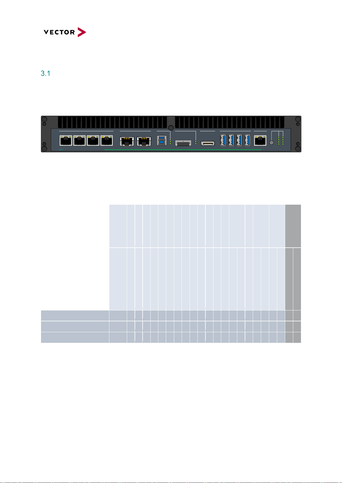
BRICK CORE COM computer core
is an actively vented high-performance Computer Core based on x86 architecture with a special
substructure for hardware time synchronized operation of 1GbE and 10GbE Logging ports based on
integrated GPS time signal or an external IEEE 802.1as time master.
1GbE/TS
1 2 3 4
10GbE
1 2
USB Client
DP
2x SATA
USB3.0
1 2 3 4
1GbE MGMT HMI
PWR
A B
1
2
3
4
BRICK CORE COM
plus
Figure 1: BRICK CORE COMplus
For the BRICK CORE COM computer core, the following HW equipment features are available for the
respective device configuration:
CPU/Graphic
Temp. Perfor. Class
RAM
RAM
Mass Storage OS
OS
1Gb Eth. IF
10Gb Eth. IF
USB
eSATA SFF8088
DP
USB Client
GPS
AUDIO
CFast
SYS CTRL
GPIO
Add-ons (not part of
the computer core)
Material
Number
Intel® Core i7® 5700EQ/GT2 P6 Active
-25 ~ 70°C @ 2,8 GHz
32 GByte 16 GByte 128GByte Industrial SSD Win® 7 Pro
6xRJ45 1Gb Ethernet 2x RJ45 10Gb Ethernet 4x USB 3.0 2x eSATA 6G SFF8088 1x Display Port USB 3.0 Client GPS
Headphone out Microphone in CFast Slot (no card) K15/Ignition Function BRICK System Com. Inte
rface
4xGPI
4xGPO
STORAGE BAY Add
-on
PCIe Add-on
BRICK CORE COM 5700EQ-16-128-ST
22510
✓
✓
opt.
✓
✓ ✓ ✓
✓ ✓ ✓ ✓ ✓ ✓ ✓ ✓ ✓ ✓ ✓ ✓ ✓
✓
-
BRICK CORE COM 5700EQ-16-128-ST-P
22511
✓
✓
opt.
✓
✓ ✓ ✓
✓ ✓ ✓ ✓ ✓ ✓ ✓ ✓ ✓ ✓ ✓ ✓ ✓ ✓ ✓
BRICK CORE COM 5700EQ-16-128-0-P
22512
✓
✓
opt.
✓
✓ ✓ ✓
✓ ✓ ✓ ✓ ✓ ✓ ✓ ✓ ✓ ✓ ✓ ✓ ✓ - ✓
- = not available
✓ = available
opt. = optional
Page 12
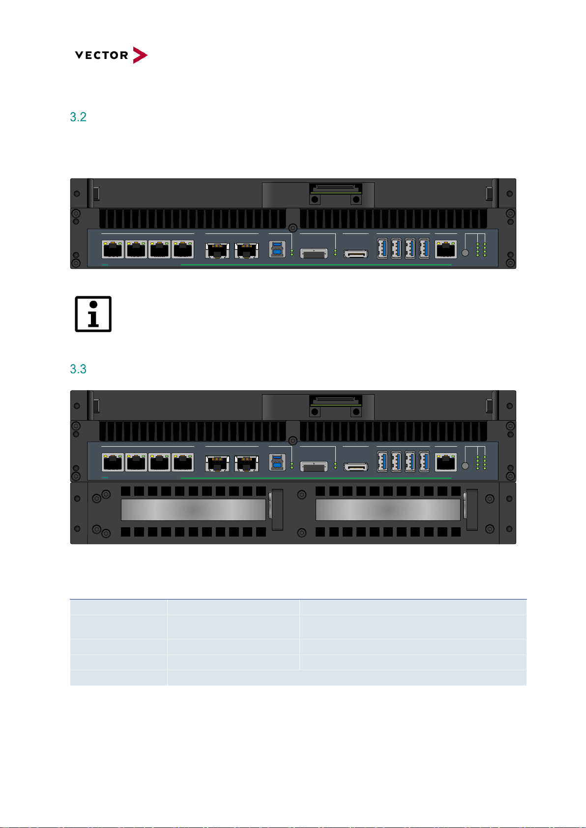
Add-On BRICK CORE COM STORAGE BAY
If large amounts of data with a high continuous band width are to be written or read the computer core
can be extended by a reception fixture for a BRICK STORAGE cartridge.
1GbE/TS
1 2 3 4
10GbE
1 2
USB Client
DP
2x SATA
USB3.0
1 2 3 4
1GbE MGMT HMI
PWR
A B
1
2
3
4
BRICK CORE COM
plus
Figure 2: BRICK CORE COMplus including STORAGE BAY attachment frame
Systems with a STORAGE BAY are always actively vented.
Add-On BRICK CORE COM PCIe
1GbE/TS
1 2 3 4
10GbE
1 2
USB Client
DP
2x SATA
USB3.0
1 2 3 4
1GbE MGMT HMI
PWR
A B
1
2
3
4
BRICK CORE COM
plus
XX XX PCIe Slot | Mech x8 ; Elec x8PCIe Slot | Mech x16 ; Elec x8
Figure 3: BRICK CORE COMplus including STORAGE BAY and PCIe Add-on
Insertion of non-validated PCIe cards may void certification and warranty.
SPC PCIe Add On
Value
Description
Operating Temperature
-25… +70°C
Add-On PCIe cards may have different specification
PCIe Slot Power
Limited power 1x 60W or 2x 30W
maximum
Power supply only via bus interface, no separate power
connector, max current all slots 5A @12V, 2A @3,3V
PCIe Slot left
Mechanical x16, electrical x8
8 Lanes PCIe 3.0 extension slot
PCIe Slot right
Mechanical x8, electrical x8
8 Lanes PCIe 3.0 extension slot
PCIe Card size
max. half size cards, 106.68 mm (height) X 175.26 mm (long), 1 Slot mounting
Page 13
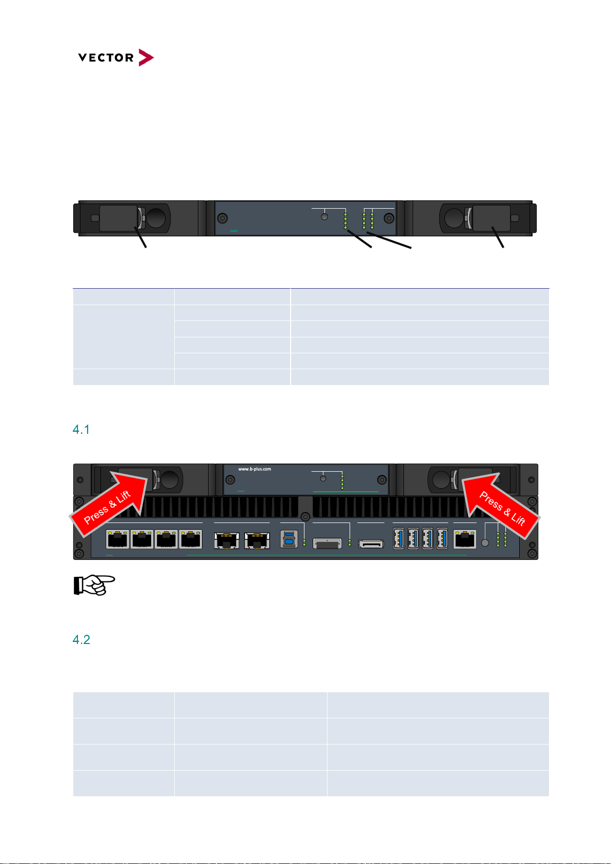
4 BRICK STORAGE
If large amounts of data with a high bandwidth are to be recorded reliably the BRICK CORE COM system
can be extended by a 1/2U (22mm) BRICK CORE COM STORAGE BAY. In this case, the STORAGE
BAY accommodates the mass storage device in the form of a BRICK STORAGE cartridge.
LOCK/UNLOCK DRIVE STATUS
BRICK STOR AGE
4 8
3 7
2 6
1 5
PCIe
LOCK
POWER
STATUS
Figure 5: BRICK STORAGE
Lock / Unlock BRICK STORAGE cartridge
1GbE/TS
1 2 3 4
10GbE
1 2
USB Client
DP
2x SATA
USB3.0
1 2 3 4
1GbE MGMT HMI
PWR
A B
1
2
3
4
BRICK CORE COM
plus
LOCK/UNLOCK
BRICK STORAGE
plus
PCIe
LOCK
POWER
STATUS
The BRICK STORAGE cartridge is not hot plug capable. Make sure your system is shut
down before you insert or remove the cartridge. Insertion or withdrawal of the BRICK
STORAGE cartridge during operation can cause data loss.
BRICK STORAGE cartridge order Information
Item number
Designation
Description
1
Fastener / Lock lever
Fastener to lock and unlock to remove cartridge
2
LED PCIe
Indicates PCI Express connection established and active
LED LOCK
Indicates cartridge locked correctly
LED POWER
Indicates Cartridge Power OK
LED STATUS
Green Indicates Status (Temp) OK. red indicates NOK (temp. low or high)
3
LED 1-8 Drive Status
Red indicates drive failure, green Drive activity
Material Number
Designation
Description
180120
BRICK STORAGE Cartridge 4TB
- 4 TB Storage prosumer SSD (0-60°C), up to 1GB/s
- RAID Controller preconfigured as RAID 0/NTFS
180121
BRICK STORAGE Cartridge 8TB
- 8 TB Storage prosumer SSD (0-60°C), up to 1GB/s
- RAID Controller preconfigured as RAID 0/NTFS
180122
BRICK STORAGE Cartridge 12TB
- 12 TB Storage prosumer SSD (0-60°C), up to 1GB/s
- RAID Controller preconfigured as RAID 0/NTFS
180123
BRICK STORAGE Cartridge 16TB
- 16 TB Storage prosumer SSD (0-60°C), up to 1GB/s
- RAID Controller preconfigured as RAID 0/NTFS
❶
❷
❸
❶
Page 14

5 Accessories
For using BRICK CORE COM in the lab or in vehicle the following accessories are available.
Material
Number
Designation
Description
22514
BRICK UPS 200
200Watt managed Li-ion UPS with 160Wh
22513
BRICK THUNDER DOCK
Highspeed Thunderbolt® Adapter to download data from a
BRICK STORAGE cartridge over a Thunderbolt® interface to a
PC-System
22442
BRICK Cable Guard
Cable Guard to secure connected cables to avoid loss cable and
connector damages.
Page 15
6 Product Identification
Scope of delivery
The scope of delivery depends on the ordered system or set configuration. Please check the scope of
delivery according to the survey printed below.
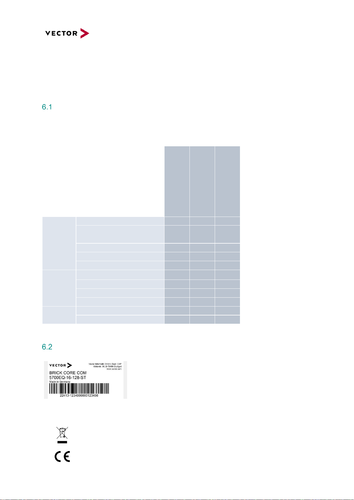
Type Plate
The type plate as shown is located on the bottom of the device.
The example data used here refer to the revision D01.
Figure 4: BRICK CORE COM type plate (example)
Symbol
Meaning
Legal notice regarding the disposal of used appliances (WEEE)
CE label
BRICK CORE COM 5700EQ
-16-128-ST
BRICK CORE COM 5700EQ
-16-128-ST-P
BRICK CORE COM 5700EQ
-16-128-0-P
Power Supply
Power supply line red-black, open end, 4qmm /1.5m
✓ ✓ ✓
Desktop type power supply AC
110-240V 50/60Hz, 220W, 24V, 9.5A
incl. Power cord EURO CEE7/7
opt.
opt.
opt.
Power cord UK (UK Plug)
opt.
opt.
opt.
Power cord USA/JP (NEMA 5-15, 3-pol)
opt.
opt.
opt.
Power cord CN (China Type 1)
opt.
opt.
opt.
Accessories
GPS-Antenna
✓ ✓ ✓
SYSCTRL Cable, KL15 yellow, FLRY 0.5qmm
✓ ✓ ✓
GPIO Cable
✓ ✓ ✓
OS Recovery Stick for Windows® / Linux
✓ ✓ ✓
Documentation
Manual BRICK CORE COM (on Recovery Stick)
✓ ✓ ✓
Safety supplement
✓ ✓ ✓
- = not available
✓ = available
opt. = optional
Page 16

7 Technical Specification
Technical Characteristics of BRICK CORE COM:
Features
Details
BRICK CORE COM 5700EQP6
Processor
Intel® Core 5700EQ 4x 2,6GHz (3,4GHz)
Graphic support
Intel® GT2 HD Graphics 5600, Base clock:
300 MHz; GT Turbo: up to 1000 MHz
Execution Units / Pixel Pipelines: 24EU / 3, Max Graphics Memory 2048MB,
GFX Memory Bandwidth (GB/s) 25.6,
GFX Memory Technology DVMT,
API (DirectX/OpenGL) 11.2 / 4.3 + OCL 2.0,
Shader Model 5.0,
Hardware accelerated Video MPEG2, VC-1, AVC, Blu-ray (+3D)
RAM
16GByte (2x 8GB SODIMM), DDR3L-1666
OS-Storage
128GByte M.2 SSD up to 512GByte M.2 SSD
Network interfaces
6x1Gbe (4x Intel® I210 Hardware Timestamp Support, 1x Intel® I210 TS 802.1AS,
1x Intel® I218LM)
2x 10Gbe (Intel X540)
USB interfaces
4xUSB3.0 Host (1000mA)
1xUSB3.0 Client (USB3380, need special software support)
Audio interfaces
Microphone input, stereo headphone output
Monitor interfaces
1xDP 1.2 (Display Port), maximum resolution: 3840x2160
External storage interfaces
CFast Slot,
2x eSATA 6G via SFF8088 plug connector
WLAN (Option)
802.11 a/b/g/n (Option)
GPS
ublox LEA-M8S
LTE
SIMCom SIM7100E 4G/LTE (project-based Option, limited certification), mini SIM
slot
GPIO
4xGPI: V_ON>1.95V, V_OFF<1.75V (+-5%), Umax 32V
4xGPO: Highside (switching of the input voltage, max. 1A per channel)
On/Off control “Ignition”
1x Digital Input via SYSCTRL plug connector (Ignition),
On: >4,75V / Off: <4,15V (+-5%), Umax 32V
BRICK system control interface
1x CAN, termination resistor switchable, 1x Digital Input (On/Off control)
Operating systems
Windows 7 Professional for embedded system
Housing dimensions
320 x (44 - 110) x 250 (B x H x T) mm (see details below)
Supply voltage
12V DC / 24 DC, safe in case of dropdown pulses (cranking) down to 6.5V
Cooling
Active (passive on request with different power / performance setup)
Power consumption typically
BRICK CORE COM based on Intel Core i7 5700EQ (without STORAGE and PCIe):
approx. 110 Watts depending on the system utilization
Power consumption maximum
BRICK CORE COM maximum rate 200W (in full configuration)
Standby (OFF) current
< 50 µA (RTC, GPS, µC Stby.)
Weight
BRICK CORE COM (without STORAGE BAY Add-on): approx. 5kg
Page 17

Environmental Characteristics and Conformity
Characteristics
Details
Operating temperature
-25°C to +70°C (for active cooled systems, without STORAGE cartridge)
Storage temperature
-40°C to +85°C
Air humidity
90% non-condensing
Vibration and shock
EN 60068-2-64:2008 (10-1000Hz – 33,8 m/s²)
EN 60068-2-27:2009 (half sine, 11ms, 500 m/s²)
IP protection class
IP2X
Electromagnetic compatibility (EMC)
RED Directive 2014/53/EU
Electrical safety
LVD Directive 2014/35/EU
RoHS II directive
2011/65/EU
USA / FCC
Part 15 Subpart B / FCC ID (W-LAN Module)
CANADA
ICES 003
BRICK Temperature Management
Critical Temperature protection for the BRICK CORE COM computing unit including Add On.
BRICK System Critical Temperature warnings (absolute maximum rates)
BRICK System Critical Temperature values
Sensors
Temperature Settings BRICK
max
min
Ambient BRICK Temp. located at backside (reference)
80
-25
Storage internal (reference)
80
-25
The critical Temperature values are continuously polled
at startup and during runtime by the BRICK µC System
HMI Indication
In a critical temp case at startup
the System will not be powered on and an Error Code
(LED) will be shown.
too high
too low
In a critical temp case during operation
the system will be set to LimpHome state (power down
but µC active) and an Error Code (LED) will be shown.
The System can only be re-powered by pressing power
button (Note: 3°C threshold)
Page 18

BRICK STORAGE cartridge temperature warnings
Critical temperature protection for BRICK CORE COM systems with BRICK STORAGE cartridge.
BRICK STORAGE cartridge temperature warnings
BSC Temperature Warning Settings
max
min
Cartridge Temperature HDD (internal)
60
>0
Cartridge Temperature SSD PRO (internal)
70
-20
Cartridge Temperature SSD industrial (internal)
tbd
-25
Storage Temperature warnings (see table), are
continuously polled by an independently µC System
HMI Indication
In a warning case (temp. out of range) at startup
the Cartridge will not be powered and a Warning LED is
set, to activate the Cartridge a restart under good
conditions is necessary
In a warning case (temp. out of range) during runtime
the Warning LED is set but the Storage keep running (to
avoid data lost) up to critical temp
Page 19

Mechanical Details:
BRICK CORE COM
Features
Details
Computer Core Unit
Base computing Unit with DC/DC power
Housing dimensions
320 x 44 x 250 (B x H x T) mm
Weight
approx. 5,0kg
Housing material and Surface
Solid aluminum housing with black anodized surface,
please note, due to this chemical process minimal differences in color are possible
All dimensions are given in millimeters [mm].
Figure 5: BRICK CORE COM mechanical drawing
Page 20

BRICK CORE COM with STORAGE BAY Add-on
Features
Details
Further external storage interfaces
Base computing Unit with DC/DC power and
PCIe 3.0-based STORAGE BAY Add-on.
Housing dimensions
320 x 66 x 250 (B x H x T) mm
Weight
approx. 5,5kg
Housing material and Surface
Solid aluminum housing with black anodized surface,
please note, due to this chemical process minimal differences in color are possible
All dimensions are given in millimeters [mm].
Figure 6: BRICK CORE COM with STORAGE BAY mechanical drawing
Page 21

BRICK CORE COM with STORAGE BAY and PCIe Add-ons
Features
Details
Further external storage interfaces
Base computing Unit with DC/DC power
PCIe 3.0-based STORAGE BAY Add-on and
PCIe Ad- on
Housing dimensions
320 x 110 x 250 (B x H x T) mm
Weight
approx. 7kg
Housing material and Surface
Solid aluminum housing with black anodized surface,
please note, due to this chemical process minimal differences in color are possible
All dimensions are given in millimeters [mm].
Figure 7: BRICK CORE COM with STORAGE BAY and PCIe mechanical drawing
Page 22

8 Product Description
BRICK CORE COM Computer Core
Front side BRICK CORE COM Computer core
1GbE/TS
1 2 3 4
10GbE
1 2
USB Client
DP
2x SATA
USB3.0
1 2 3 4
1GbE MGMT HMI
PWR
A B
1
2
3
4
BRICK CORE COM
plus
Figure 8: BRICK CORE COMplus front view connectors
Pos.
Designation
Description
1 Mounting holes with inner thread M4 (depth approx. 11.5mm)
2 Air outlets left and right for actively vented BRICK CORE COM systems
3
1GbE/TS 1,2,3,4
1Gb Ethernet Port (dedicated I210 per Port, TS-capable)
4
10GbE, 1,2
10Gb Ethernet Port (TR-capable need XTSS TR license)
5
USB Client
USB 3.0 Client Port (need project-based software support)
6
DP
Display Port
7
2xSATA
2xSATA 6G via SFF8088 (only Lanes 1 and 2 are supported)
8
USB3.0 1,2,3,4
USB3.0 Port
9
1GbE MGMT
1Gb Ethernet Port (adapted for System Management via Remote Desktop)
10
HMI PWR
On/Off button
11
HMI LED A1-4, B1-3
User LED (controlled via application software SIODI), see details in chapter 9.9
12
HMI LED B4
Operating status indication (Power LED), see details in chapter 9.9
❸
❹
❺
❻
❼
❽
❾
❿
⓬
⓫
❷
❶
❶
Page 23

Rear side BRICK CORE COM Computer core
ON
1 2
GPS
OPT1 OPT2
1 2
WLAN
AUDIO 802.1AS CFast SIM SYSCTRL
CAN
OPT
1 2
3 4
1 2 3 4
5 6 7 8
GPIO POWER 12/24V =
Figure 9: BRICK CORE COMplus rear view connectors
Pos.
Designation
Description
1 - Mounting holes with inner thread M4 (depth approx. 11.5mm)
2 - Air intake opening left and right for actively vented BRICK CORE COM systems
3
GPS
GPS Antenna connection
4
OPT1
HF SMA connector for option (i.e. LTE)
5
OPT2
HF SMA connector project specific option
6
WLAN 1,2
WLAN Antenna connection (Prim, Aux)
7
MIC Symbol
Audio input, stereo microphone
8
SPK Symbol
Audio output, stereo headphones
9
Temp
Opening for temperature sensors for system temperature management
10
802.1AS
1Gb Ethernet Port (optional: with specific time synchronization function)
11
Cover plate for CFast
and miniSIM socket
CFast Slot (CFast not included in the scope of delivery)
miniSIM socket (need option LTE)
12
SYSCTRL
BRICK System control connector
13
SYSCTRL SW
DIP-Switch for CAN termination for the system control connector
14
GPIO
4 GPI and 4 GPO
15
POWER
Power supply connector
❸
❹
❺
❻
❼
❽
❾
❿
⓬
⓫
⓭
⓮
⓯
❷
❶
❶
Page 24

BRICK CORE COM with STORAGE BAY
Depending on the configuration, a BRICK CORE COM system may be equipped with a STORAGE BAY.
Front side BRICK CORE COM with STORAGE BAY
1GbE/TS
1 2 3 4
10GbE
1 2
USB Client
DP
2x SATA
USB3.0
1 2 3 4
1GbE MGMT HMI
PWR
A B
1
2
3
4
BRICK CORE COM
plus
Figure 10: BRICK CORE COMplus front view STORAGE BAY connectors
Pos.
Designation
Description
1 Mounting holes with inner thread M4 (depth approx. 11.5mm)
2 Guide rollers
3 Connection terminal for the STORAGE CARTRIDGE
Into the STORAGE BAY, A STORAGE CARTRIDGE can be inserted from the front.
+ =
Figure 11: BRICK CORE COM STORAGE insert
Inserting or withdrawal of the BRICK STORAGE cartridge during operation can cause data
loss.
More information about the BRICK STORAGE cartridge can be found in the chapter referring
to accessories.
❶
❷
❸
❷
❶
Page 25

9 Interfaces, Control Elements and Indicators
1GbE/TS 1/2/3/4
These connectors are designed as RJ45 sockets with integrated LEDs and correspond to a 1000BASE-
T Ethernet interface according to IEEE 802.3 clause 40.
With activated Platform Timesync Service PTSS (part of BRICK XTSS) these ports are hardware time
synchronized with the defined time master and are able do a timestamp capturing of incoming data
frames.
Pin
Signal
RJ45 Network socket 1-4
1
GBEx_MDI0+
Figure 12: Pin assignment 1GbE/TS
2
GBEx_MDI0-
3
GBEx_MDI1+
4
GBEx_MDI2+
5
GBEx_MDI2-
6
GBEx_MDI1-
7
GBEx_MDI3+
8
GBEx_MDI3-
LED on the right
ACT = green
LED on the left
LINK100 = yellow
LINK1000 = green
Pin ❶
Pin ❽
Page 26

10GbE 1/2
These connectors are designed as RJ45 sockets with integrated LEDs and correspond to a 10GBASE-
T Ethernet interface according to IEEE 802.3an.
With activated Platform Timesync Service PTSS (part of BRICK XTSS) these ports are hardware time
synchronized with the defined time master. With activated XTSS-TR (time-relay) this ports can
synchronize connected IEEE 802.1AS devices like MDILink.
Pin
Signal
RJ45 Network socket 1-2
1
GBEx_MDI0+
Figure 13: Pin assignment 10GbE/TS
2
GBEx_MDI0-
3
GBEx_MDI1+
4
GBEx_MDI2+
5
GBEx_MDI2-
6
GBEx_MDI1-
7
GBEx_MDI3+
8
GBEx_MDI3-
USB Client
Pin
Signal
USB 3.0 Type B socket
1
VBUS
Figure 14: Pin assignment USB Client
2
D- 3 D+
4
GND 5 SSTX-
6
SSTX+
7
GND 8 SSRX-
9
SSRX+
Matching counterpart: USB 3.0 Type B plug and USB 1.0/2.0 Type B plug
This Port need project-based software adaption, this is not included in standard OS package
Pin ❸
Pin ❾
Pin ❽
Pin ❼
Pin ❺
Pin ❻
Status
Pin ❷
Pin ❹
Pin ❶
Page 27

DP (DisplayPort)
Pin
Signal
DisplayPort socket 20-pole
1
LANE0+
Figure 15: Pin assignment DisplayPort
2
GND 3 LANE0-
4
LANE1+
5
GND 6 LANE1-
7
LANE2+
8
GND 9 LANE2-
10
LANE3+
11
GND
12
LANE3-
13
CONFIG1
14
CONFIG2
15
AUX+
16
GND
17
AUX-
18
HPD
19
RTN_PWR
20
PWR
Matching counterpart: Customary DisplayPort cables.
It is recommended to use high-quality DisplayPort cables, especially for longer cable
lengths. The use of DisplayPort to HDMI and DisplayPort to DVI adapters is possible but,
also in this case, high-quality components should be used.
Pin ❶
Page 28

2x Serial ATA (SATA) Port
Pin
Signal
Mini SAS x4 socket / SFF-8088 socket
A1
GND
Figure 16: Pin assignment mini SAS x4
A2
SFF_SATA1_RXP
A3
SFF_SATA1_RXN
A4
GND
A5
SFF_SATA0_RXP
A6
SFF_SATA0_RXN
A7
GND
A8
Not connected
A9
Not connected
A10
GND
A11
Not connected
A12
Not connected
A13
GND
B1
GND
B2
SFF_SATA1_TXP
B3
SFF_SATA1_TXN
B4
GND
B5
SFF_SATA0_TXP
B6
SFF_SATA0_TXN
B7
GND
B8
Not connected
B9
Not connected
B10
GND
B11
Not connected
B12
Not connected
B13
GND
Matching counterpart: Mini SAS plug (SFF-8088)
Please note that only the Lanes 1 and 2 are supported by BRICK CORE COM
A1
A13
B13
B1
Page 29

USB3.0 Port 1/2/3/4
In the basic configuration, the system is provided with four USB 3.0 interfaces. To the USB interfaces,
various USB devices can be connected. Both ports are equipped with a current limit at 1000mA.
Pin
Signal
USB3.0 Type A sockets
1
VBUS *1
Figure 17: Pin assignment USB3.0 1/2/3/4
2
D- 3 D+ 4 GND
5
RX- 6 RX+
7
GND 8 TX-
9
TX+
*1 Overcurrent protection by self-resetting fuse (maximally 1000mA)
Matching counterpart: In order to achieve the data transmission rates typical for
USB3.0 connecting cables with USB3.0 type A plugs have to be used. Besides, the
connected peripheral devices have to support USB3.0.
Also a connection of devices with USB1.0/2.0 type A plugs is possible.
1GbE MGMT Port
Pin
Signal
RJ45 Network socket
1
GBEx_MDI0+
Figure 18: Pin assignment 1GbE MGMT
2
GBEx_MDI0-
3
GBEx_MDI1+
4
GBEx_MDI2+
5
GBEx_MDI2-
6
GBEx_MDI1-
7
GBEx_MDI3+
8
GBEx_MDI3-
This Ethernet port is not recommended for data capturing (No TS), it can be used for
connecting the BRICK to a LAN for setup or maintenance.
Pin ❶
Pin ❽
Pin ❾
Pin ❽
Pin ❼
Pin ❻
Pin ❺
Pin ❶
Pin ❷
Pin ❸
Pin ❹
Page 30

HMI Power
Pin
Signal
1 VIN+ typ. 12/24V (6V – 32V)
Figure 19: Pin assignment HMI PWR
2
VIN- 3 VIN+ typ. 12/24V (6V – 32V)
4
VIN-
Matching counterpart:
Molex MiniFit Sr. Receptiple Housing Art.-Nr.: 42816-0212
Molex Female Crimp Terminal 12, 10 & 8 AWG Art.-Nr.: 42815-0012
HMI Power button and LEDs
System Override: the microcontroller-based system management controller may override the
user programmed LED state in case of the described system warning or system shut down to
limp home state.
LED
Signal
PWR
On/Off button
Figure 20: HMI Power button and LEDs
A1
User LED
Programmable by SIODI application software
A2
A3
A4
B1
User LED
Programmable by SIODI application software
B2
User/System
Programmable by SIODI application software
System override: red BRICK UPS config error
B3
User/System
Programmable by SIODI application software
System override: red: System down state low temp
B4
System Status
Green: Indication of operating status (Power LED)
System override: System down state high temp
Pin ❷ / ❹
Pin ❶ / ❸
Page 31

GPS SMA/F
SMA socket, for using GPS antennas with SMA/M plug.
Pin
Signal
SMA socket
1
SMA GPS
Figure 21: Pin assignment GPS
2
Insulation
3
GND
SMA Port OPT1/2
SMA-RP (reverse polarity) socket, e.g. for connecting customary antennas with SMA-RP plug.
If used for LTE antenna 4G/LTE/GPS with SMA/M connector a gender changer is needed.
SMA-RP WLAN 1/2
SMA-RP (reverse polarity) socket, e.g. for connecting customary WLAN antennas with SMA-RP plug.
Pin
Signal
SMA-RP socket
1
SMA WLAN (1 prim, 2 aux)
Figure 23: Pin assignment WLAN 1/2
2
Insulation
3
GND
Matching counterpart: SMA-RP plug
Pin
Signal
SMA-RP socket
1
Option 1 SMA (preferred for LTE)
Option 2 SMA-RP project specific
Figure 22: Pin assignment OPT1/2
2
Insulation
3
GND
Page 32

Microphone Input
This connector can be used for connection of a microphone.
- Pre-amplifier with selectable 0 dB, +10 dB, +20 dB, and +30 dB gain settings
- Programmable, low-noise MIC bias level
Pin
Signal
Description
3.5mm jack socket
1
Sleeve
Ground
Figure 24: Pin assignment microphone
2
Ring
Right channel with stereo plugs, negative phase
with symmetrical connections
3
Tip
Left channel with stereo plugs, positive phase
with symmetrical connections, signal („hot“) with
mono connectors
Matching counterpart: 3.5mm stereo jack plug (TRS plug)
Page 33

Headphones Output
This connector is suitable for connecting wired headphones and earphones to the BRICK CORE COM.
A connection of actively intensified audio devices to this connector is not recommended as this may
cause an overregulation of the audio signal.
- 101 dB Dynamic range (A-wtd)
- -89 dB THD+N
- Minimum impedance 16 Ohm
- Maximum output power 50mW per channel
Pin
Signal
Description
3.5mm jack socket
1
Sleeve
Ground
Figure 25: Pin assignment headphones
2
Ring
Right channel with stereo plugs, negative phase
with symmetrical connections
3
Tip
Left channel with stereo plugs, positive phase
with symmetrical connections, signal („hot“) with
mono connectors
Matching counterpart: 3.5mm stereo jack plug (TRS plug)
Page 34

1GbE/802.1AS
This connector is designed as a RJ45 sockets with integrated LEDs and corresponds to a network
interface according to IEEE 802.1AS that can be used for timing and synchronization of time-critical
applications.
With activated Platform Timesync Service PTSS and Cluster Timesync (BRICK XTSS) this port can be
the time master alternatively to the internal GPS for PTSS and CTSS.
It is also able do a timestamp capturing of incoming data frames.
Pin
Signal
RJ45 Network socket
1
GBEx_MDI0+
Figure 26: Pin assignment 1GbE 802.1AS
2
GBEx_MDI0-
3
GBEx_MDI1+
4
GBEx_MDI2+
5
GBEx_MDI2-
6
GBEx_MDI1-
7
GBEx_MDI3+
8
GBEx_MDI3-
Pin ❶
Pin ❽
Page 35

CFast Slot
Pin
Signal
SATA Segment
S1
GND
Figure 27: Pin assignment CFast
S2
TX+
S3
TX-
S4
GND
S5
RX-
S6
RX+
S7
GND
Key
Power Segment
PC1
CDI (Card Detect In)
PC2
GND
PC3
Not connected
PC4
Not connected
PC5
Not connected
PC6
Not connected
PC7
GND
PC8
Not connected
PC9
Not connected
PC10
Not connected
PC11
Not connected
PC12
Not connected
PC13
3.3V PC14
3.3V PC15
GND PC16
GND
PC17
Not connected
S1
S7
PC1
PC17
Page 36

SYSCTRL (internal System Control)
Pin
Signal
3.50mm Pitch connector and DIP switch
1
CAN_HIGH
Figure 28: Pin assignment SYSCTRL
2
IGN_IN, Thresholds: On: >4,75V / Off: <4,15V (+-5%),
Umax 32V
3
CAN_LOW
4
n.c.
DIP switch 1 defines the CAN bus termination
DIP switch 2 is reserved for future applications
Configuration
1 2 CAN Termination (120R)
ON
OFF
This CAN Interface is for BRICK System internal use to connect
System components like BRICK UPS
Matching counterpart:
Molex UltraFit Receptiple Housing Art.-Nr.: 172258-1004
Molex Female Crimp Terminal 22 & 20 AWG Art.-Nr.: 172253-3123
Page 37

GPIO General Purpose I/Os
Pin
Signal
1 OUT4
Figure 29: Pin assignment GPIOs
2
OUT3
3
OUT2
4
OUT1
5
IN4 6 IN3 7 IN2
8
IN1
IN
Input
Switching thresholds: V_ON >1.95V, V_OFF<1.75V (+-5%),
Umax 32V, internal pull down 10K
OUT
Output Voltage
Highside (switching input voltage), max. 1A per channel
Max programmable switching frequency 1Hz
Matching counterpart:
Molex UltraFit Receptiple Housing Art.-Nr.: 172258-1008
Molex Female Crimp Terminal 22 & 20 AWG Art.-Nr.: 172253-3123
Electrical characteristics Input/Output
Symbol
Description
Value
Unit
Min
Typ
Max
VIN
Input voltage continuous full load
10
12
32 V V
IN min
Input voltage (short-term crank safe)
6,5
V
V
GPI,LOW
GPI Low voltage
1,75
V
V
GPI,HIGH
GPI High voltage
1,95 V V
GPI max
GPI input voltage max
32
V
R
IN,GPI
GPI input resistance
10 kΩ
V
IGN_IN,LOW
IGN_IN Input Low voltage
4,15
V
V
IGN_IN,HIGH
IGN_IN Input High voltage
4,75 V V
IGN_IN max
IGN_IN input voltage max
32
V
R
IN,IGN_IN
IGN_IN input resistance
12 kΩ
V
GPO
GPO output voltage
VIN
32
V
I
GPO max
GPO output current max
1 A f
GPO min
GPO output frequency
1
Hz
Page 38

10 Typical Installation
Vehicle Power Wiring Diagram BRICK CORE COM and UPS (for reference
only)
Figure 30: Power Wiring Diagram BRICK CORE COM and BRICK UPS
Page 39

11 BIOS/UEFI BRICK CORE COM 5700EQP616G
11
Determination of the BIOS version
To determine the current BIOS version please check the system information tab within the BIOS.
Operation
In the BIOS setup, the system behavior can be adapted to individual requirements. The BIOS setup
offers a series of menus to make changes to the system and to switch features on or off.
The Setup Utility changes system behavior by modifying the Firmware configuration. The setup
program uses a number of menus to make changes and turn features on or off.
Function keys during POST:
[F2]
Enter BIOS Setup
[F5]
Boot Menu
[ESC] + [2]
Enter BIOS Setup via Remote Keyboard in Console Redirection Mode
Function keys in the setup:
[F1]
Help
[F9]
Load default settings
[F10]
Save and Exit
.
This chapter describes important settings to be used for operation of the BRICK CORE
COM. All necessary settings are BIOS default (F9). Special Add-On configuration
(SPC) may need different settings.
Please consult your manufacturer before adjusting parameters in BIOS to avoid
functional restrictions of your BRICK CORE COM.
Page 40

Advanced HDD Configuration
Parameters
Options
Description
SATA Device
Enabled
Disabled
General activation of the SATA function
SATA Speed Limit
Auto
Gen 2
Gen 1
Fastest SATA speed
Interface Combination
IDE
AHCI
RAID
Defines the interface type of the mass
storage
Aggressive Link Power
Disabled
Enabled
Aggressive Link Power Management
for HDD Ports
ComExpress SATA0
Port Enable -> Disable, Enable
Hot Plug -> Disable, Enable
SATA Device Type -> Hard Disk
Drive, Solid State Drive
eSATA-Lane 1
ComExpress SATA1
Port Enable -> Disable, Enable
Hot Plug -> Disable, Enable
SATA Device Type -> Hard Disk
Drive, Solid State Drive
eSATA-Lane 2
ComExpress SATA2
Port Enable -> Disable, Enable
Hot Plug -> Disable, Enable
SATA Device Type -> Hard Disk Drive,
Solid State Drive
M.2-based internal SSD
Page 41

ComExpress SATA3
Port Enable -> Disable, Enable
Hot Plug -> Disable, Enable
SATA Device Type -> Hard Disk Drive,
Solid State Drive
CFast-Slot
Please note that, upon misadjustment of these parameters, the system does not boot any
more or data on the corresponding data media are even destroyed. Besides, misadjustment
may cause that data media are no longer recognized.
Advanced South Bridge Configuration
Parameters
Options
Description
SMBUS Device
Disabled
Enabled
Activates/Deactivates SMBUS Device
State After G3
State S5
State S0
Last State
S5 System works in the ATX mode
Page 42

Advanced Onboard UART & CPLD Configuration
Parameters
Options
Description
Serial Port 0
Disabled
Enabled
COM UART SER0 is not available!
Serial Port 1
Disabled
Enabled
COM UART SER1 is not available!
GPIO IRQ
Disabled
14
15
Configuration IRQ for GPIO pins
I2C IRQ
Disabled
14
15
Configuration IRQ of the I2C controller
Page 43

12 Commissioning and Maintenance
In order to avoid injuries and damage caused by direct or indirect contact with hot surfaces the
following instructions must be observed:
BRICK CORE COM must be positioned and installed in a maintenance area or in an operating
facility of limited access.
The users having permission to enter the maintenance area or the operating facility must have
received adequate instructions regarding the risks.
Important instructions!
For positioning and installation or removal of the BRICK CORE COM System, please observe
the relevant instructions given in this user manual.
The device must only be positioned and installed by maintenance personnel responsible in this
area (that is familiar with the associated risks).
The device can be operated in all positions except with the upper side downwards.
In order to avoid overheating of the platform, keep a distance of at least 100 mm to the upper
cooling fins of the chassis (passively cooled variant).
In case of installation in a housing (e.g. a control cabinet): The housing (control cabinet) must
have enough space for the BRICK CORE COM System and the corresponding spaces for air
circulation and cable connections. Moreover, the housing must have sufficient, possibly active,
ventilation to avoid overheating.
The cooling fins and the inlet and discharge openings of the housing must not be blocked
(covered).
Page 44

Initial commissioning
1. Connect the DC supply cable of the power supply unit to the rear side (1) of the BRICK CORE COM
system.
ON
1 2
GPS
OPT1 OPT2
1 2
WLAN
AUDIO 802.1AS CFast SIM SYSCTRL
CAN
OPT
1 2
3 4
1 2 3 4
5 6 7 8
GPIO POWER 12/24V =
2. Connect a suitable monitor which is able to display a resolution of at least X x Y to the display
port (2) at the front side. (Later the resolution can be reduced)
1GbE/TS
1 2 3 4
10GbE
1 2
USB Client
DP
2x SATA
USB3.0
1 2 3 4
1GbE MGMT HMI
PWR
A B
1
2
3
4
BRICK CORE COM
plus
3. Connect a compatible mouse to the USB port (e.g. 3).
1GbE/TS
1 2 3 4
10GbE
1 2
USB Client
DP
2x SATA
USB3.0
1 2 3 4
1GbE MGMT HMI
PWR
A B
1
2
3
4
BRICK CORE COM
plus
4. Connect a compatible keyboard to the USB port.
1GbE/TS
1 2 3 4
10GbE
1 2
USB Client
DP
2x SATA
USB3.0
1 2 3 4
1GbE MGMT HMI
PWR
A B
1
2
3
4
BRICK CORE COM
plus
❶
❷
❸
❹
Page 45

5. Connect the table power pack to the mains supply by using the country-specific network supply
line
6. For BRICK CORE COM with STORAGE BAY Add-on please insert Cartridge
1GbE/TS
1 2 3 4
10GbE
1 2
USB Client
DP
2x SATA
USB3.0
1 2 3 4
1GbE MGMT HMI
PWR
A B
1
2
3
4
BRICK CORE COM
plus
LOCK/UNLOCK
BRICK STORAGE
plus
PCIe
LOCK
POWER
STATUS
7. Please start the BRICK CORE COM system via the power button (5). Hold the button down until
the LED B4 (6) turns green.
For vehicle installation you can use IGNITION IN (SYS Controll) for boot and shut
down the system.
1GbE/TS
1 2 3 4
10GbE
1 2
USB Client
DP
2x SATA
USB3.0
1 2 3 4
1GbE MGMT HMI
PWR
A B
1
2
3
4
BRICK CORE COM
plus
LOCK/UNLOCK
BRICK STORAGE
plus
PCIe
LOCK
POWER
STATUS
8. The system will now boot the operating system defined in the scope of delivery. The LED B4 (6)
will first shine red before turning green.
1GbE/TS
1 2 3 4
10GbE
1 2
USB Client
DP
2x SATA
USB3.0
1 2 3 4
1GbE MGMT HMI
PWR
A B
1
2
3
4
BRICK CORE COM
plus
LOCK/UNLOCK
BRICK STORAGE
plus
PCIe
LOCK
POWER
STATUS
❺
❻
Page 46

BRICK Core COM 5700EQP6 Operating system
Your system will be delivered, depending on the configuration, with an operating system installed.
If you have ordered your BRICK CORE COM with a preinstalled operating system all drivers are installed
in accordance with the ordered system configuration. When switched on the first time, the system will
be fully operational. Please observe the following instruction.
Important information when using pre-installed "WINDOWS 7 PROFESSIONAL
FOR EMBEDDED SYSTEMS" operating systems:
The terms and conditions for using the pre-installed operating systems are defined in
the document "Microsoft Software License Terms".
Page 47

Handling of internal components
This section contains important information about the safe handling of internal components. Please
follow the instructions when handling all internal components of the BRICK CORE COM systems.
When installing or removing additional plug-in cards, please follow the following instructions:
Please observe the “general safety instructions for IT equipment” and installation
instructions.
The installation and removal of additional plug-in cards may only be made by a
qualified trained employee in accordance with the instructions of this manual.
Before removing the device cover please make sure that your system is switched off
and disconnected from the voltage supply.
Please observe the safety instructions regarding electrostatically sensitive
components (ESC). Failure to observe this warning may cause damage to the device
or components of the device.
The BRICK CORE COM system might get hot during operation and should not be
touched without adequate precautions. There is danger of burning.
 Loading...