

Page 1
Contact Temperature Sensor SC-T
Contact Temperature Sensor SC-T
Contact Temperature Sensor SC-T
Item Name
Probe
Definition
Cable length
SC-Tn3-2
NTC 3kΩ at 25°C (77°F)
B
25/50
3935
2m, (6.5ft)
SC-Tn10-2
NTC 10kΩ at 25°C (77°F)
B
25/50
3935
SC-Tn11-2
NTC 10kΩ at 25°C (77°F)
B
25/50
3630
SC-Tn12-2
NTC 10kΩ at 25°C (77°F)
B
25/50
3380
SC-Tn20-2
NTC 20kΩ at 25°C (77°F)
B
25/50
4200
SC-Tn100-2
NTC 100kΩ at 25°C (77°F)
B
25/50
4200
SC-Tp1-2
PT100
EN60751
SC-Tp2-2
PT1000
EN60751
SC-Tk5-2
NI1000
5000 ppm/K
AMS-2
Tightening strap for ½-3in pipes
AMS-3
Tightening strap for 3-6in pipes
Sensing Probe
Thermistor:
Range: (Probe only)
Accuracy:
-40…0°C (-40…32°F):
0…50°C (32…122°F):
50…100°C (122…212°F):
> 100°C (> 212°F):
NTC
-70…150°C (-94…302°F)
0.5 K
0.2 K
0.5 K
1 K
Platinum-Film:
Range: (Probe only)
Accuracy
PT according EN 60751
-70…200°C (-94…392°F)
EN 60751, Class B, ask for other class
Nickel Thin Layer:
Range: (Probe only)
Accuracy
1000 Ω at 0°C, 5000 ppm/K
-60…200°C (-76…392°F)
DIN 43760
Cable
Standard
Size
Insulation material
Operating Temperature
Ratings
2 x 0.20 mm2 (AWG 24)
PVC
-40…80°C (-40…176°F)
UL758, 1581/CSA C22.2 No 210.2
High temperature
Size
Insulation material
Operating temperature
Ratings
-H
2 x 0.35 mm2 (AWG 22)
FEP
-60...200°C (-76…392°F)
ULR/CSA C22.2 No 210.2
Plenum rated
Size
Insulation material
Operating temperature
Ratings
-P
2 x 0.5 mm2 (AWG 20)
Plenum PVC
-20…75°C (-4…167°F)
UL C(UL) PLENUM CMP OR E355847
FPLP UL
Single insulated PVC
Size
Insulation material
Operating Temperature
Ratings
-A
2 x 0.20 mm2 (AWG 24)
PVC
-40…80°C (-40…176°F)
UL758,1581 CSA C22.2 No.210.2
Environment
Operation
Climatic conditions
Temperature depends on cable
type
To IEC 721-3-3
class 3K5
See above
Transport & storage
Climatic conditions
Temperature
Humidity
Mechanical conditions
To IEC 721-3-2 and IEC 721-3-1
class 3K3 and class 1K3
-40…80°C (-40…176°F)
< 95% RH non-condensing
class 2M2
Standards
conform according to
EMC Standard 89/336/EEC
EMEI Standard 73/23/EEC
EN 61 000-6-1/ EN 61 000-6-3
Automatic electrical controls for
household and similar use
Special requirement on
temperature dependent controls
EN 60 730 –1
EN 60 730 – 2 – 9
Pollution Class
Normal acc. to EN 60 730,
RoHS compliant
Degree of Protection
IP65 to EN 60 529
Safety Class
III (IEC 60536)
Housing
Probe
Brass
Dimensions (Diameter x L)
Probe: ø 6 x 35 mm (ø 0.25” x 1.4”)
Contact Plate: 20x30mm (0.8” x 1.2”)
Weight (including package)
80g (2.8oz)
SC-Tn10-2A
Cable type:
default: PVC cable double insulated
-H = High temperature
-P = Plenum rated
-A = PVC cable single insulated
Cable length in Meter
Sensing Element (see below)
Sensor Type: Sensor with flying lead
20
(0.8)
35 (1.4)
30 (1.2)
6 (0.2)
SC-T
SC-T, Flying Lead Contact Temperature Sensor
Features
Thermistors and PT sensing elements to fit your system
Strap-On mounting for pipes or arched surfaces
Simple installation
Wide range of temperature probes
Including 2m (6.5ft) wire
Applications
Measure temperature for heating, ventilation and air conditioning
applications
For heating or cooling mode detection in 2-pipe systems
As frost protection sensor
Temperature sensor
The sensor measures the temperature by use of a glass packed thermistor
with a negative temperature coefficient (NTC), a platinum film (PT) or a nickel
thin layer (NI) based probe. Its resistance changes according to the
temperature. The change follows a specified curve. A summary of such curves
is printed on the back of this document. Contact our sales department for
curves or sensing elements not yet listed below.
Compensating conductor resistance
The length and type of conductors used to connect the sensor to the
measuring electronic influences the accuracy of the measurement. Especially
for elements with low resistance this has to be taken into account.
Compensation needs to be performed by the measurement electronics.
Ordering
Technical Specification
Warning! This device is intended to be used for comfort applications. Where a
device failure endangers human life and/or property, it is the responsibility of the
owner, designer and installer to add additional safety devices to prevent or detect
a system failure caused by such a device failure. The manufacturer of this device
cannot be held liable for any damage caused by such a failure.
Failure to follow specifications and local regulations may endanger life, cause
equipment damage and void warranty.
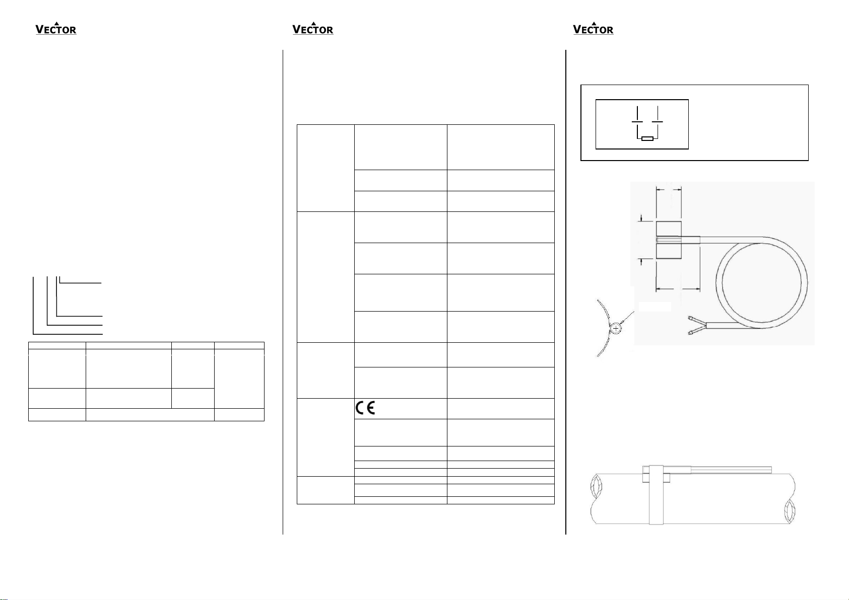
Wiring & Installation
Wiring Diagram
Dimensions [mm](in)
Installation
Mount the sensor on a supply or return pipe depending on application.
Make sure the maximum allowed temperature limit is not exceeded.
For better temperature transfer between sensor and medium use heat
conducting paste or heat conducting pads.
If possible place the sensor on the upper side of the pipe to prevent
permeation by condensate.
Bend the wings of the contact sensor to fit to the radius of the pipe.
Place the heat conducting pad or liquid between pipe and sensor and use the
tightening strap to fix the sensor to the pipe. Use moderate torque, do not
crush the sensor.
Doc: 70-00-0215A, V1.0, 20140722 © 2012-2014 Vector Controls GmbH, Switzerland Subject to alteration
www.vectorcontrols.com
Page 2
Contact Temperature Sensor SC-T
Contact Temperature Sensor SC-T
Contact Temperature Sensor SC-T
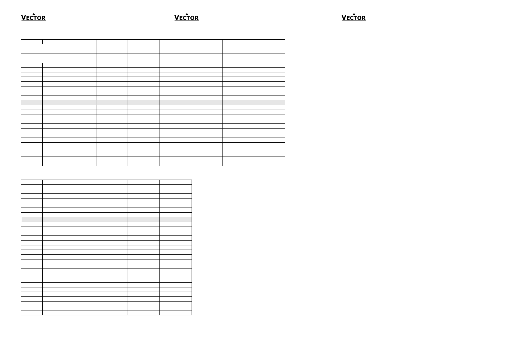
°C
°F
Tn3 [kΩ]
Tn5 [kΩ]
Tn10 [kΩ]
Tn11 [kΩ]
Tn12 [kΩ]
Tn20 [kΩ]
Tn100 [kΩ]
B
25/50
3935
3470
3935
3630
3380
4200
4200
B
25/85
3974
3535
3974
3687
3435
4260
4260
B
25/100
3988
3526
3988
3715
3455
4285
4285
Signal type
NTC 3k
NTC 5k
NTC 10k-2
NTC-10k-3
NTC 20k
NTC 100k
-50
-58
201,1
161,9
670,2
441,3
329,2
1711
8558
-40
-40
100,9
89,49
336,4
239,7
188,4
814,0
4095
-30
-22
53,09
54,07
177,0
135,3
111,3
415,6
2077
-20
-4
29,12
33,21
97,08
78,91
67.74
220,6
1105
-10
14
16,60
21,07
55,33
47,54
42.45
122,4
612,4 0 32
9,795
13,73
32,65
29,49
27.28
70,20
351,0
10
50
5,969
9,041
19,90
18,79
17.96
41,56
207,8
20
68
3,747
6,064
12,49
12,26
12.09
25,34
126,7
25
77
3,000
5,000
10,00
10,00
10,00
20,00
100,00
30
86
2,417
4,139
8,057
8,194
8,313
15,88
79,43
40
104
1,598
2,875
5,327
5,592
5,828
10,21
51,06
50
122
1,081
2,032
3,603
3,893
4,161
6,718
33,60
60
140
0,746
1,463
2,488
2,760
3,021
4,518
22,59
70
158
0,525
1,069
1,751
1,990
2,229
3,100
15,50
80
176
0,376
0,792
1,255
1,458
1,669
2,168
10,84
90
194
0,275
0,601
0,915
1,084
1,266
1,542
7,707
100
212
0,203
0,464
0,678
0,817
0,973
1,114
5,571
110
230
0,536
0,354
0,512
0,624
0,752
0,818
4,092
120
248
0,123
0,272
0,410
0,481
0,605
0,609
3,046
130
266
0,097
0,212
0,322
0,380
0,487
0,460
2,298
140
284
0,077
0,169
0,257
0,300
0,395
0,351
1,755
150
302
0,063
0,137
0,210
0,240
0,325
0,271
1,356
°C
°F
Tp1 [Ω]
Tp2 [Ω]
Tk5 [Ω]
Tk6 [Ω]
PT100
DIN 60751
PT1000
DIN 60751
NI1000,
K=5000
NI1000
K=6180
-50
-58
80,28
803,0
790,88
742,55
-40
-40
84,27
843,0
830,84
791,31
-30
-22
88,22
882,0
871,69
841,46
-20
-4
92,16
922,0
913,48
892,96
-10
14
96,09
961,0
956,24
945,82
0
32
100,00
1000,0
1000
1000
10
50
103,90
1039,0
1044,79
1055,52
20
68
107,79
1078,0
1090,65
1111,36
30
86
111,67
1117,0
1137,62
1170,56
40
104
115,54
1155,0
1185,71
1230,11
50
122
119,40
1194,0
1234,98
1291,05
60
140
123,24
1232,0
1285,45
1353,40
70
158
127,07
1270,5
1337,15
1417,21
80
176
130,89
1309,0
1390,12
1482,50
90
194
134,70
1347,0
1444,39
1549,34
100
212
138,50
1385,0
1500,00
1617,79
110
230
142,29
1423,0
1556,98
1687,89
120
248
146,06
1460,5
1615,37
1759,72
130
266
149,80
1498,0
1675,19
1833,35
140
284
153,60
1536,0
1736,48
1908,87
150
302
157,30
1573,0
1799,27
1986,35
160
320
161,05
1610,5
1863,60
2065,89
170
338
164,75
1647,5
1929,50
2147,58
180
356
168,45
1684,5
1997,00
2231,53
190
374
172,15
1721,5
2066,15
2317,83
200
392
175,85
1758,5
2136,96
2406,60
Resistance Table for Thermistors (NTC)
Resistance Table for Platinum Film and NI1000 Elements
Doc: 70-00-0215A, V1.0, 20140722 © 2012-2014 Vector Controls GmbH, Switzerland Subject to alteration
www.vectorcontrols.com
 Loading...