

Page 1

Quick Startup Guide for
SIMOVERT MASTERDRIVES
6SE70 VC
Vector Control
Section 1: Parameterization of Base Dri ve
Section 2: Parameterization of Rectifier
Section 3: Simovis Trace Setup Method
Section 4: When Should a Drive be re-Tuned
DROM-02069
Page 2

We reserve the right to modify functions, technical data, standards, drawings and parameters.
We have checked the contents of this document to ensure that they coincide
with the described hardware and software. However, deviations cannot be
completely ruled-out, so we cannot guarantee complete conformance.
However, the information in this document is regularly checked and the
necessary corrections will be included in subsequent editions. We are thankful
for any recommendations or suggestions.
e-mail:
Page 2 Version 1.0 March 1, 2000
mailto:drives.support@sea.siemens.com
Page 3

NOTE:
These instructions do not purport to cover all details or variations in equipment, nor to
provide for every possible contingency to be met in connection with installation,
operation or maintenance. Should further information be desired or should particular
problems arise which are not covered sufficiently for the purchaser’s purposes, please
contact your local Siemens office.
Further, the contents of these instructions shall neither become a part of nor modify
any prior or existing agreement, commitment or relationship. The sales contract
contains the entire obligation of Siemens Energy & Automation. The warranty
contained in the contract between the parties is the sole warranty of Siemens Energy &
Automation. Any statements contained herein do not create new warranties nor
modify the existing warranty.
Note:
This Quick Startup Guide is not an autonomous document, but is intended to direct users to
the section in the Operating Instructions which are important for start-up. Thus, these brief
instructions can only be completely valid when used in conjunction with the Operating
Instructions. It is especially important to observe the warning and information regarding
potential hazards in the Operating Instructions.
Warning:
• Electrical equipment has parts an components which are at hazardous voltage levels.
• If the warning information in the detailed Operating Instructions is not observed, this
can result in severe bodily injury or material damage.
• Only appropriately qualified personnel may work with this equipment.
• These personnel must be knowledgeable with all of the warning information and
service/maintenance measures of the Operating Instruction.
Perfect and safe operation of this equipment assumes professional transport, storage, erection
and installation as well as careful operating control and service.
Version 1.0 March 1, 2000 Page 3
Page 4

Page 4 Version 1.0 March 1, 2000
Page 5

Section 1:
Parameterization of Base Unit
SIMOVERT MASTERDRIVES
6SE70 VC
Vector Control
1.1 Power Section Defintion
1.2 Factory Reset
1.3 Basic Start-up
1.3.1 Volts/Hz without encoder feedback
1.3.2 Volts/Hz with encoder feedback
1.3.3 Vector Control without encoder feedback
1.3.4 Vector Control with encoder feedback
1.4 Drive Control Word
1.5 Communication Board Configuration
Note: Refer to Operating Instruction Manual for power and control connections.
Version 1.0 March 1, 2000 Page 5
Page 6

Page 6 Version 1.0 March 1, 2000
Page 7
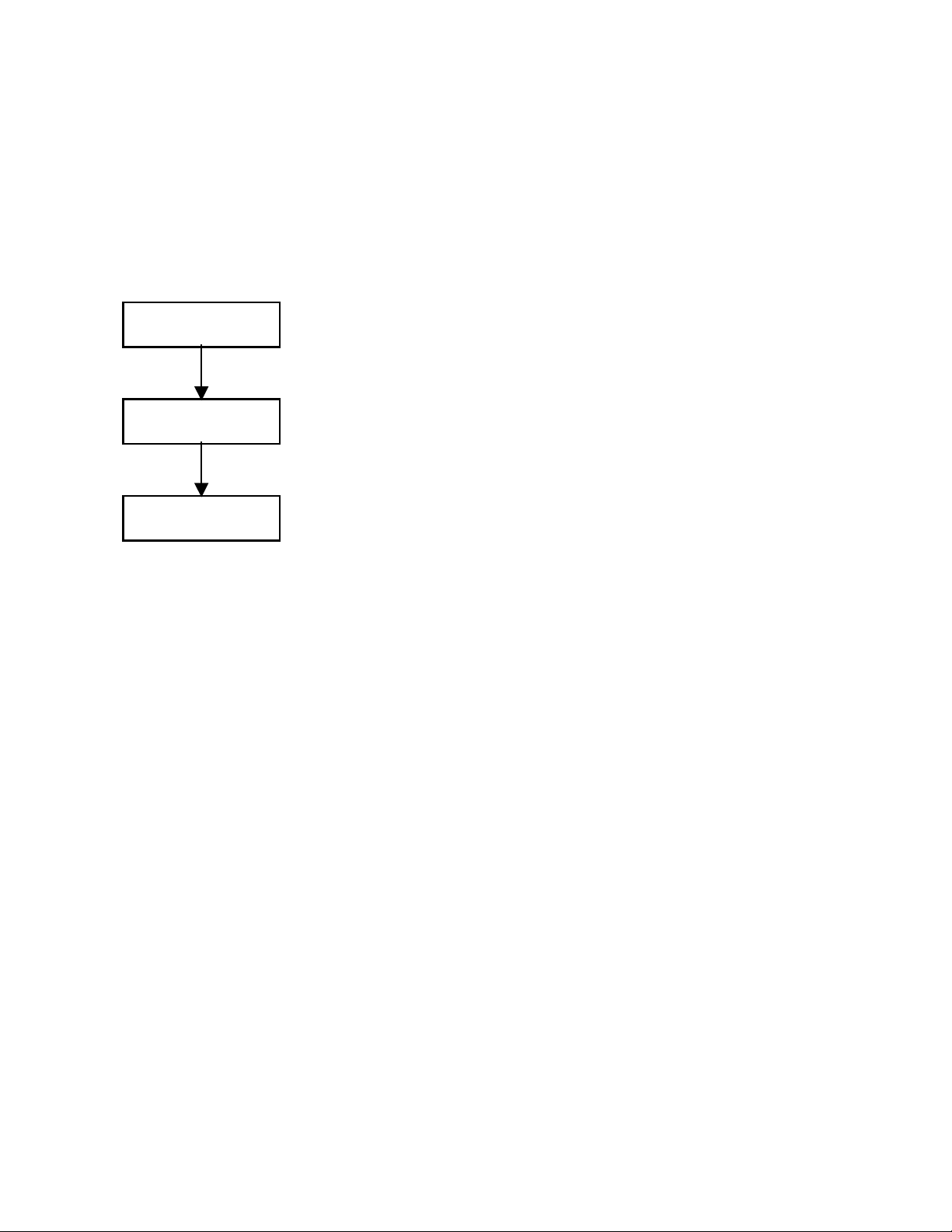
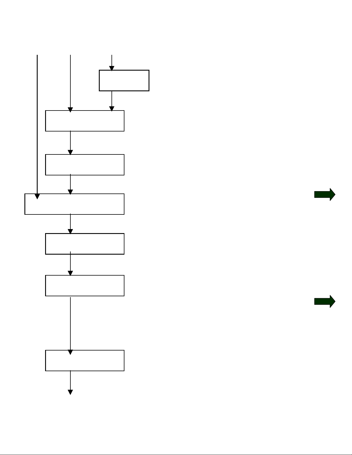
1.1 Power Section Definition
Note: Power Section is pre-defined at the factory. Power Section
Definition is required if a new board CUVC board is put into the drive or
boards are switched between units with different ratings. Drive should
be defaulted and re-parameterized after Power Section Definition.
P060 = 8
P070 = ?
P060 = 1
Select “Power Section Definition”
Menu
Input Code for unit (PWE)
(Refer to Compendium section
6.3 or use the bookmark “PWE
Listing” or check the following
table)
Return to Parameter Menu
Version 1.0 March 1, 2000 Page 7
Page 8

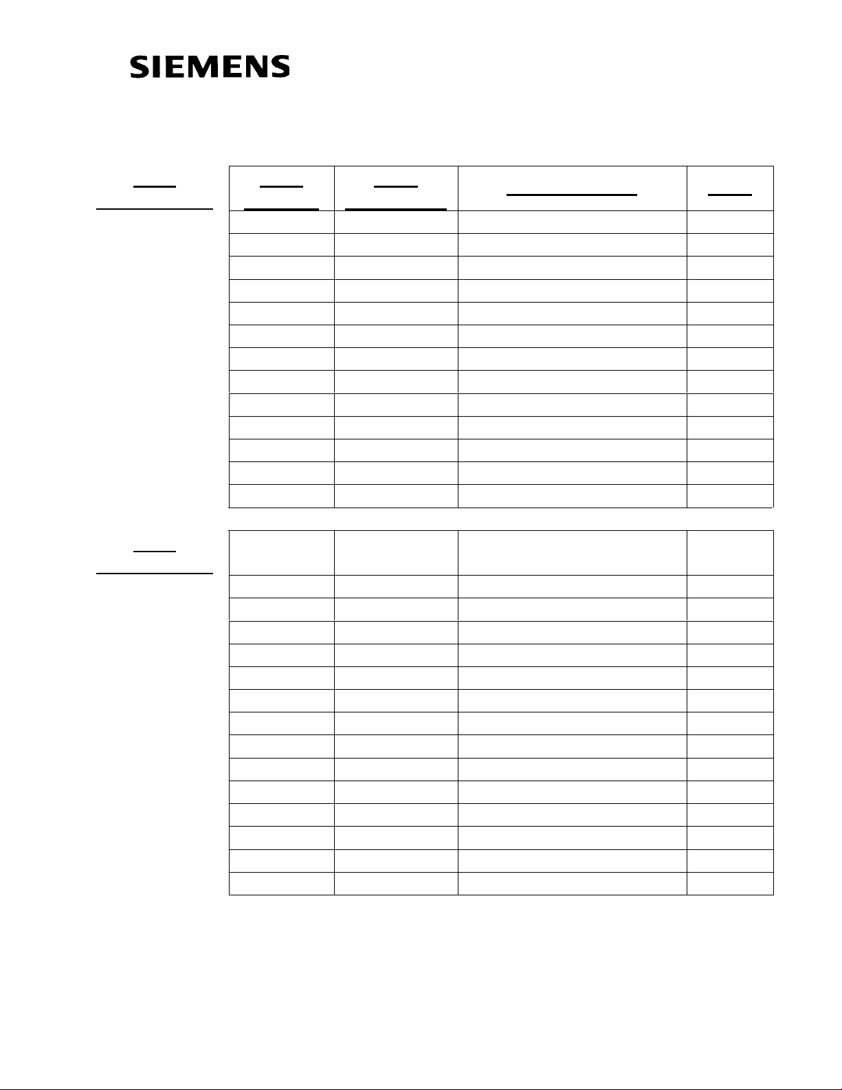
Unit List
P070: Parameter Value (PWE)
P072: Rated Output Current in Amps In[A]
Frequency Converter
AC-AC type
3 AC 200V to 230V
PWE Order Number In[A]
14 6SE7021-1CA60 10.6 21 6SE7021-3CA60 13.3 27 6SE7021-8CB60 17.7 32 6SE7022-3CB60 22.9 39 6SE7023-2CB60 32.2 48 6SE7024-4CC60 44.2 54 6SE7025-4CD60 54.0 64 6SE7027-0CD60 69.0 70 6SE7028-1CD60 81.0 13 6SE7031-0CE60 100.0 29 6SE7031-3CE60 131.0 41 6SE7031-6CE60 162.0 87 6SE7032-0CE60 202.0
*1
Frequency Inverter
DC-AC type
DC 270V to 310V
PWE Order Number In[A]
15 6SE7021-1R60 10.6
22 6SE7021-3RA60 13.3
28 6SE7021-8RB60 17.7
33 6SE7022-3RB60 22.9
40 6SE7023-2RB60 32.2
49 6SE7024-4RC60 44.2
55 6SE7025-4RD60 54.0
65 6SE7027-0RD60 69.0
71 6SE7028-1RD60 81.0
20 6SE7031-0RE60 100.0
34 6SE7031-3RE60 131.0
86 6SE7031-6RE60 162.0
92 6SE7032-0RE60 202.0
*1
Page 8 Version 1.0 March 1, 2000
Page 9

Frequency Converter
AC-AC type
3 AC
380V to 460V
Air Cooled
PWE
PWE
Order Number In[A]
Water
Cooled
3 6SE7016-1EA61 6.1
9 6SE7018-0EA61 8.0
11 6SE7021-0EA61 10.2
18 6SE7021-3EB61 13.2
25 6SE7021-8EB61 17.5
35 6SE7022-6EC61 25.5
42 6SE7023-4EC61 34.0
46 6SE7023-8ED61 37.5
52 6SE7024-7ED61 47.0
56 6SE7026-0ED61 59.0
66 6SE7027-2ED61 72.0
74 6SE7031-0EE60 92.0
82 6SE7031-2EF60 124.0
90 6SE7031-5EF60 146.0
98 6SE7031-8EF60 186.0
102 6SE7032-1EG60 210.0
108 6SE7032-6EG60 260.0
112 6SE7033-2EG60 315.0
116 6SE7033-7EG60 370.0
147 233 6SE7035-1EK60 510.0
151 237 6SE7036-0EK60 590.0
164 168 6SE7037-0EK60 690.0
*1
1
*
Version 1.0 March 1, 2000 Page 9
Based on 3kHz carrier frequency setting, larger frames have maximum carrier
frequency restrictions
Page 10

Frequency Inverter
DC-AC type
DC
510V to 650V
PWE
Air Cooled
PWE
Water
Order Number In[A]
Cooled
4 6SE7016-1TA61 6.1
10 6SE7018-0TA61 8.0
12 6SE7021-0TA61 10.2
19 6SE7021-3TB61 13.2
26 6SE7021-8TB61 17.5
36 6SE7022-6TC61 25.5
43 6SE7023-4TC61 34.0
47 6SE7023-8TD61 37.5
53 6SE7024-7TD61 47.0
57 6SE7026-0TD61 59.0
67 6SE7027-2TD61 72.0
75 6SE7031-0TE60 92.0
83 6SE7031-2TF60 124.0
91 6SE7031-5TF60 146.0
99 6SE7031-8TF60 186.0
103 6SE7032-1TG60 210.0
109 6SE7032-6TG60 260.0
113 6SE7033-2TG60 315.0
117 6SE7033-7TG60 370.0
120 206 6SE7035-1TJ60 510.0
123 209 6SE7036-0TJ60 590.0
126 212 6SE7037-0TK60 690.0
127 213 6SE7038-6TJ60 860.0
134 6SE7041-1TM60 1100.0
135 221 6SE7041-1TK60 1100.0
140 226 6SE7041-3TM60 1300.0
150 236 6SE7041-6TM60 1630.0
153 239 6SE7042-1TQ60 2090.0
154 199 6SE7041-3TL60 1300.0
163 167 6SE7037-0TJ60 690.0
181 247 6SE7038-6TS60 6450.0
185 250 6SE7041-1TS60 6270.0
194 244 6SE7042-5TN60 2470.0
*1
Page 10 Version 1.0 March 1, 2000
Page 11

Frequency Converter
AC-AC type
3 AC
500V to 575V
Air Cooled
PWE
PWE
Order Number In[A]
Water
Cooled
1 6SE7014-5FB61 4.5
5 6SE7016-2FB61 6.2
7 6SE7017-8FB61 7.8
16 6SE7021-1FB61 11.0
23 6SE7021-5FB61 15.1
30 6SE7022-2FC61 22.0
37 6SE7023-0FD61 29.0
44 6SE7023-4FD61 34.0
50 6SE7024-7FD61 46.5
60 6SE7026-1FE60 61.0
62 6SE7026-6FE60 66.0
68 6SE7028-0FF60 79.0
78 6SE7031-1FF60 108.0
84 6SE7031-3FG60 128.0
94 6SE7031-6FG60 156.0
100 6SE7032-0FG60 192.0
104 6SE7032-3FG60 225.0
136 222 6SE7033-0FK60 297.0
141 227 6SE7033-5FK60 354.0
143 229 6SE7034-5FK60 452.0
*1
1
*
Version 1.0 March 1, 2000 Page 11
Based on 3kHz carrier frequency setting, larger frames have maximum carrier
frequency restrictions
Page 12

Frequency Inverter
DC-AC type
DC
675V to 810V
PWE
Air Cooled
PWE
Water
Order Number In[A]
Cooled
2 6SE7014-5UB61 4.5
6 6SE7016-2UB61 6.2
8 6SE7017-8UB61 7.8
17 6SE7021-1UB61 11.0
24 6SE7021-5UB61 15.1
31 6SE7022-2UC61 22.0
38 6SE7023-0UD61 29.0
45 6SE7023-4UD61 34.0
51 6SE7024-7UD61 46.5
61 6SE7026-1UE60 61.0
63 6SE7026-6UE60 66.0
69 6SE7028-0UF60 79.0
79 6SE7031-1UF60 108.0
85 6SE7031-3UG60 128.0
95 6SE7031-6UG60 156.0
101 6SE7032-0UG60 192.0
105 6SE7032-3UG60 225.0
110 200 6SE7033-0UJ60 297.0
114 202 6SE7033-5UJ60 354.0
118 204 6SE7034-5UJ60 452.0
121 207 6SE7035-7UK60 570.0
124 210 6SE7036-5UK60 650.0
128 214 6SE7038-6UK60 860.0
130 216 6SE7041-0UM60 990.0
132 218 6SE7041-1UM60 1080.0
138 224 6SE7041-2UM60 1230.0
144 230 6SE7041-4UM60
6SE7041-4UQ60
148 234 6SE7042-1TQ60
6SE7041-6UQ60
155 195 6SE7041-1UL60 1080.0
157 6SE7042-4ULJ60 2450.0
159 197 6SE7041-1UL60 1230.0
*1
1400.0
1580.0
Page 12 Version 1.0 March 1, 2000
Page 13
Frequency Inverter
DC-AC type
DC
675V to 810V
Air Cooled
Frequency Converter
AC-AC type
3 AC
660V to 690V
Air Cooled
PWE
PWE
Order Number In[A]
Water
Cooled
161 6SE7043-3UR60 3270.0
165 6SE7044-1UR60 4090.0
169 6SE7044-8UR60 4900.0
173 6SE7045-7UR60 5720.0
177 6SE7046-5UR60 6540.0
179 245 6SE7036-5UR60 4940.0
182 248 6SE7038-6US60 6540.0
186 251 6SE7041-1US60 6160.0
188 253 6SE7041-2US60 5840.0
190 240 6SE7042-1UN60 2050.0
192 242 6SE7042-3UN60 2340.0
PWE
PWE
Order Number In[A]
Water
Cooled
58 6SE7026-0HF60 55.0
72 6SE7028-2HF60 82.0
76 6SE7031-0HG60 97.0
80 6SE7031-2HF60 118.0
88 6SE7031-5HF60 145.0
96 6SE7031-7HG60 171.0
106 6SE7032-1HG60 208.0
137 223 6SE7033-0HK60 297.0
142 228 6SE7033-5HK60 354.0
146 232 6SE7034-5HK60 452.0
*1
*1
Frequency Inverter
DC-AC type
DC
890V to 930V
PWE
Air Cooled
PWE
Water
Order Number In[A]
Cooled
59 6SE7026-0WF60 60.0
73 6SE7028-2WF60 82.0
Version 1.0 March 1, 2000 Page 13
*1
Page 14

DC
890V to 930V
PWE
Air Cooled
PWE
Water
Order Number In[A]
Cooled
77 6SE7031-0WG60 97.0
81 6SE7031-2WF60 118.0
89 6SE7031-5WF60 145.0
97 6SE7031-7WG60 171.0
107 6SE7032-1WG60 208.0
111 201 6SE7033-0WJ60 297.0
115 203 6SE7033-5WJ60 354.0
119 205 6SE7034-5WJ60 452.0
122 208 6SE7035-7WK60 570.0
125 211 6SE7036-5WK60 650.0
129 215 6SE7038-6WK60 860.0
131 217 6SE7041-0WM60 990.0
133 219 6SE7041-1WM60 1080.0
139 225 6SE7041-2WM60 1230.0
145 231 6SE7041-4WM60
6SE70414WQ60
149 235 6SE7041-6WM60
6SE7041-6WM60
152 238 6SE7034-5WK60 452.0
156 196 6SE7041-1WL60 1080.0
158 6SE7042-4WR60 2450.0
160 198 6SE7041-2WL60 1230.0
162 6SE7043-3WR60 3270.0
166 6SE7044-1WR60 4090.0
170 6SE7044-8WR60 4900.0
174 6SE7045-7WR60 5720.0
178 6SE7046-5WR60 6540.0
180 246 6SE7036-5WS60 4940.0
183 249 6SE7038-6WS60 6540.0
187 252 6SE7041-1WS60 6160.0
189 254 6SE7041-2WS60 5840.0
191 241 6SE7042-1WN60 2050.0
193 243 6SE7042-3WN60 2340.0
*1
1400.0
1580.0
Page 14 Version 1.0 March 1, 2000
Page 15
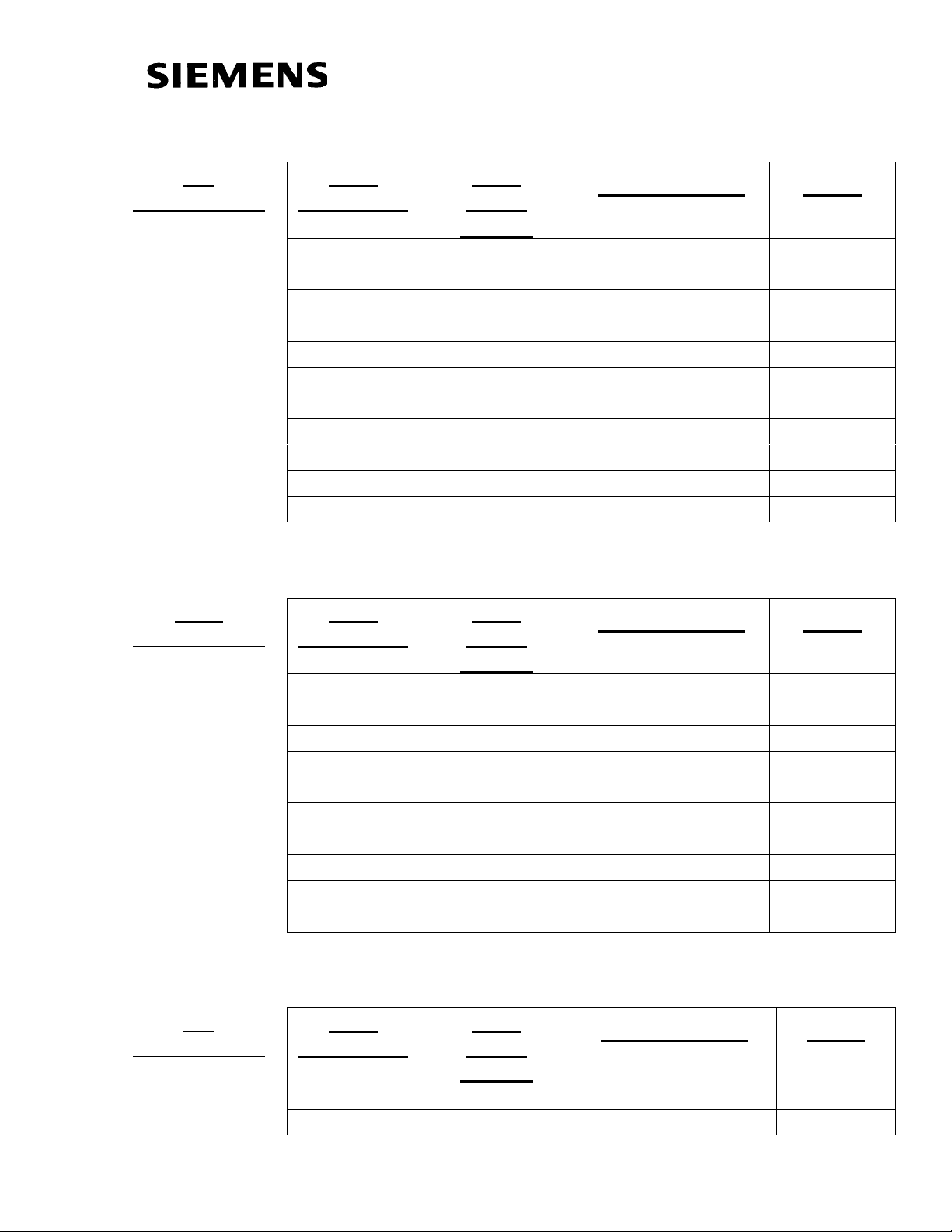
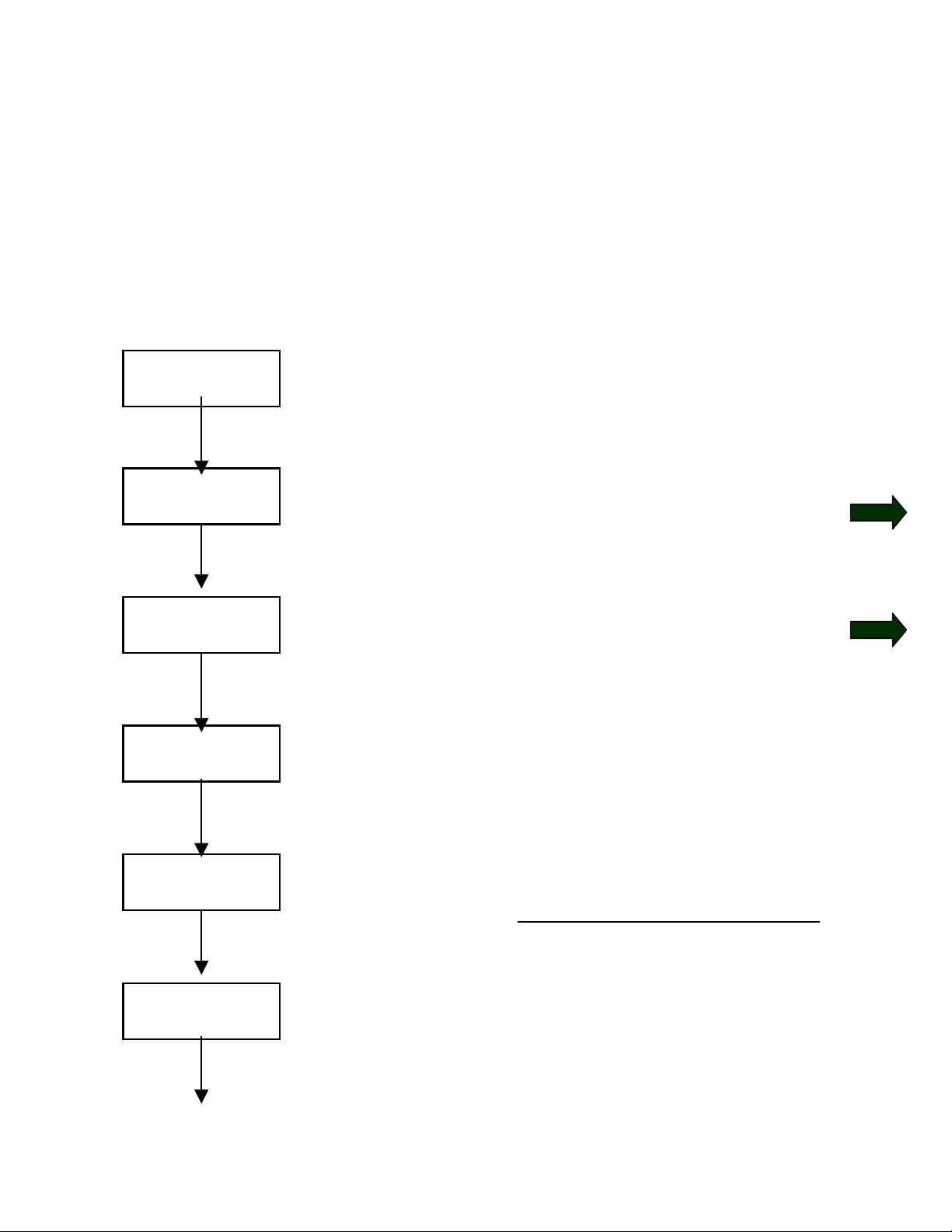
1.2 Factory Reset
P053 = 6
P060 = 2
P366 = 0
P970 = 0
6: Parameter Changes permitted
via PMU and Serial Interface
(OP1 and PC)
2: Menu Select = Fixed Settings
Select Factory Setting
0: Standard
Start Parameter Reset
0: Parameter Reset
1: No Parameter Change
Version 1.0 March 1, 2000 Page 15
Page 16

Page 16 Version 1.0 March 1, 2000
Page 17
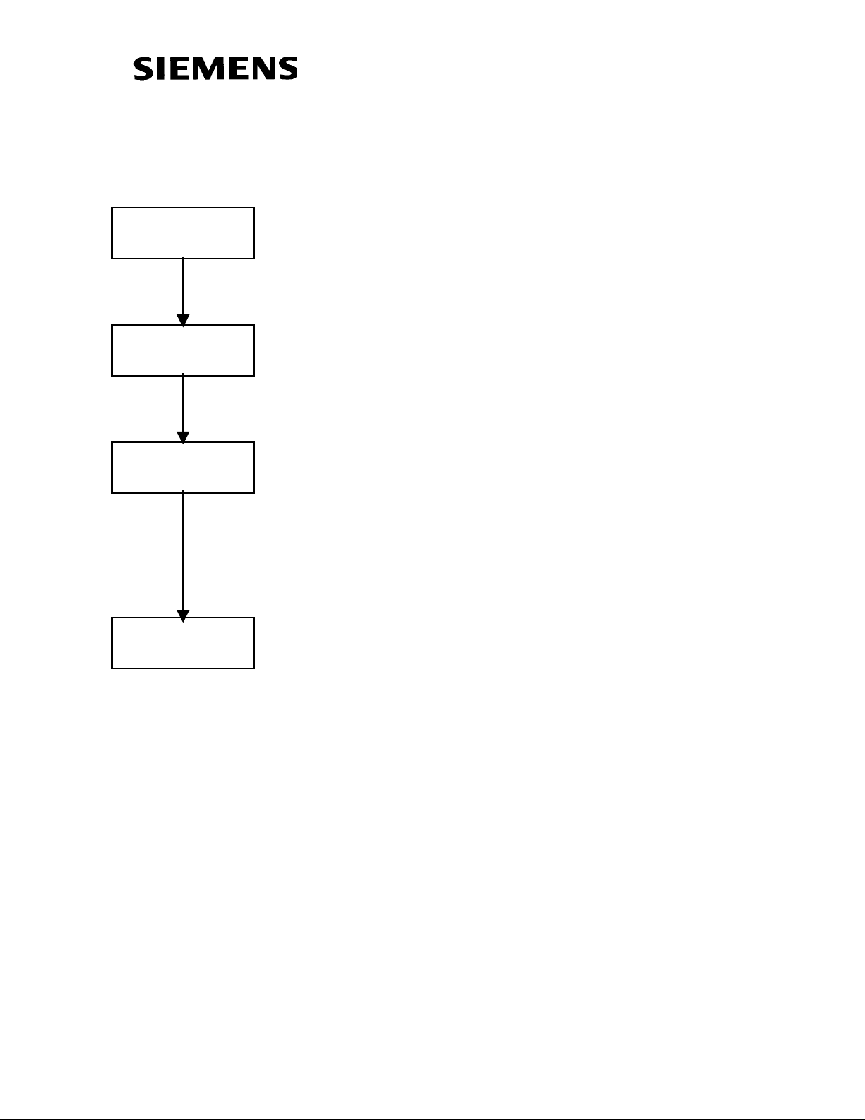
1.3 Basic Start-up without Motor Connected to Load
1.3.1 Volts/Hz without Encoder
P060 = 5
P071 = ?
P095 = ?
P095 = 2 10 or 11
P097 = ?
P060=5
Select “Drive Settings”
P071 = Input Line Voltage
AC-AC Converter=460Volt
DC-AC Inverter = 620Volt
P095 = Select Motor Type
2: Asynchronous 1PH7 Motor
10: IEC Induction Motor
11: NEMA Induction Motor
P097 = Motor Code number for
1PH7 motor (See Appendix)
P101 = 460
P102 = xxx
P095 = 10 11
P104 = ?
P105 = ?
Motor Nameplate Information
P101= Motor Voltage (V)
P102 = Motor Rated Current (A)
P104 = Cos (phi) per nameplate
P105 = Rated Horsepower
Version 1.0 March 1, 2000 Page 17
Page 18
P106 = ?
P107 = 60
P108 = xxxx
P115 = 1
P340 = 3
P106 = NEMA Motor Nameplated
efficiency (if unknown set =0.8)
P107 = Rated Motor Frequency
P108 = Nameplated Rotor RPM
P115 = 1
“Automatic Parameterization”
P340 = Carrier Frequency
Low # = Cooler Motor and Drive
High # = Lower Motor Noise
P383 = xxxx
P452 = 100
P383 = Motor Thermal Time
Constant. If constant unknown use
general guidelines;
2 Pole Motor = 480 seconds
4 Pole Motor = 600 seconds
6 Pole Motor = 720 seconds
P452 = Maximum Forward Speed in
Percentage (usually 100%)
Page 18 Version 1.0 March 1, 2000
Page 19

P453 = -100
P060 = 1
P128 = xxxx
P462 = xxxx
P453 = Maximum Reverse Speed in
Percentage (usually -100%)
P060 = Return to Parameter Menu
P128 = Maximum Motor Current
Options: P128 = P102
P128=1.1*P102
P128=1.5*P102
P462 = Acceleration Time in seconds
P464 = Deceleration Time in seconds
P464 = xxxx
P443i2= 11
P443i2(Index2) = 11
Configures drive for analog input
(0-10Vdc) to be active at
terminals X101 pin#15 and
pin#16
If 4-20mA is required closed
CUVC board mounted jumper
S3, position 1 and 2.
Start/Stop Control is located on
the PMU (operator control panel
mounted directly on the drive)
Speed Setpoint is controlled with
the Up / Down arrows.
Version 1.0 March 1, 2000 Page 19
Page 20

Connect External Wiring as connection diagram.
r
Custome
Connection Points
Internal Connections
Step 1: Dry set of contacts between terminals X101, pin#1 and pin#5 for Local/Remote Mode Selection. Jumper if not required.
Step 2: Dry set of contacts between terminals X101, pin#1 and pin#8 for
Coast to Stop Selection. Jumper if not required.
Step 3: Dry set of contacts between terminals X101, pin#1 and pin#9 for Source of Main Start/Stop Selection.
Step 4: Dry set of contacts between terminals X101, pin#1 and pin#7 for
Source of Fault Reset. Leave open if not required. “P” button on PMU
will be fault reset location if pin#7 is not used.
Step 5: Dry set of contacts between terminals X101, pin#1 and pin#6 for
Fixed Speed or Preset Speed Selection. Leave open if not required.
Page 20 Version 1.0 March 1, 2000
Page 21

Speed value is determined by P402. A selection of P402=100% will be
a full speed reference setpoint.
Step 6: Fault Status is provided by a 24 Vdc signal at terminals X101
pin#3 with respect to pin#2. Leave open if not required.
Step 7: Drive Operating Status is provided by a 24 Vdc signal at
terminals X101 pin#4 with respect to pin#2.
Step 8: Connect external speed reference 0-10Volt or 4-20 mA (CUVC
board mounted jumper S3 pin 2 and 2 must be closed for mA input).
Adjust over the full range and monitor P447. With a zero input r447
should read near 0.00, and with full value r447 should read near 100%.
Step 9: Connect the motor to the load, unless the plan is to install an
encoder feedback or change to Vector Control.
Standard Commissioning for a Volts/Hz
controlled motor without feedback is
complete, after adjusting only 19
parameters.
Version 1.0 March 1, 2000 Page 21
Page 22

1.3.2 Volts/Hz with Encoder
Note: Complete section 1.3.1 before operating the motor with encoder feedback.
P060 = 5
P100 = 0
P130 = ?
P151 = ?
P060=5
Select “Drive Settings”
P100=0
Selects Volts/Hz
with Encoder Feedback
P130 = Select Type of Encoder
11: Pulse Encoder
15: Pulse Encoder with Zero Pulse
P151 = Pulse Per Revolution (PPR)
P060 = 1
Page 22 Version 1.0 March 1, 2000
P060 = Return to Parameter Menu
Page 23

Additional Connection for +15 Vdc Encoder.
Step 10: Set Speed Reference to 20%.
Step 11: Provide Start command. Note that if Signal A and Signal B are
reversed, the motor will accelerate rapidly.
Step 12: Connect the motor to the load, unless the plan is to change to
Vector Control.
Standard Commissioning for a Volts/Hz
controlled motor with feedback is
complete, after adjusting only 24
parameters.
Version 1.0 March 1, 2000 Page 23
Page 24

1.3.3 Vector Control without Encoder Feedback
Note: Complete section 1.3.1 (Volts/Hz control without encoder feedback).
P060 = 5
P100 = 3
P060 = 1
P115 = 4
P060=5
Select “Drive Settings”
P100=3
Selects Vector Control
without Encoder Feedback
P060 = Return to Parameter Menu
If you plan to use an encoder, go to
section1.3.4, otherwise continue.
P115 = 4 No-Load Measurement
Uncoupled motor will ROTATE.
Alarm message “A080” will appear,
and a start command must be issued
within 20 seconds to perform the test,
otherwise P115 will unset.
Wait
Page 24 Version 1.0 March 1, 2000
This test will adjust the following
parameters
P103, P120
Wait for display to change back
o
to
009.
Page 25

P115=5
Wait
P115=5 Controller Optimization
Alarm message “A080” will appear,
and a start command must be issued
within 20 seconds to perform the test,
otherwise P115 will unset.
This test is best performed on a
coupled motor under actual conditions;
however, if the load is cyclic (0-100%
load variation), manual tuning may be
preferred.
This test will adjust the following
parameters
P116, P223, P235, P236,
P240, P471
Step 10: Set Speed Reference to 20%, and monitor speed feedback r000, current feedback r004, and actual DC BUS r006. If stable increase speed in increments and continue to monitor feedbacks.
Standard Commissioning for a Vector
Controlled motor without feedback is
complete, after adjusting only 24
parameters, and utilizing two of the selftuning options.
Version 1.0 March 1, 2000 Page 25
Page 26
1.3.4 Vector Control with Encoder Feedback
Note: Complete section 1.3.1 (Volts/Hz control without encoder feedback), and
section 1.3.3 (Vector control without encoder feedback)
Step 10: Operate the uncoupled motor if sections 1.3.1 and 1.3.3 are complete and
verify operation of the motor without faults.
P060=5
P060 = 5
P100 = 4
Select “Drive Settings”
P100=4
Selects Vector Control
with Encoder Feedback
Connect encoder as per
diagram
P130 = ?
P151 = ?
P060 = 1
P115 = 4
P130 = Select Type of Encoder
11: Pulse Encoder
15: Pulse Encoder with Zero Pulse
P151 = Pulse Per Revolution (PPR)
P060 = Return to Parameter Menu
P115 = 4 No-Load Measurement
Uncoupled motor will ROTATE.
Alarm message “A080” will appear,
and a start command must be issued
within 20 seconds to perform the test,
otherwise P115 will unset.
Page 26 Version 1.0 March 1, 2000
Page 27

Wait
P115=5
Wait
This test will adjust the following
parameters
P103, P120
Wait for display to change back
o
to
009.
P115=5 Controller Optimization
Alarm message “A080” will appear,
and a start command must be issued
within 20 seconds to perform the test,
otherwise P115 will unset.
This test is best performed on a
coupled motor under actual conditions;
however, if the load is cyclic (0-100%
load variation), manual tuning may be
preferred.
This test will adjust the following
parameters
P116, P223, P235, P236,
P240, P471
Step 11: Set Speed Reference to 20%, and monitor speed feedback r000, current feedback r004, and actual DC BUS r006. If stable increase speed in increments and continue to monitor feedbacks.
Standard Commissioning for a Vector
Controlled motor with feedback is
complete, after adjusting only 31
parameters, and utilizing two of the selftuning options.
Version 1.0 March 1, 2000 Page 27
Page 28

Page 28 Version 1.0 March 1, 2000
Page 29

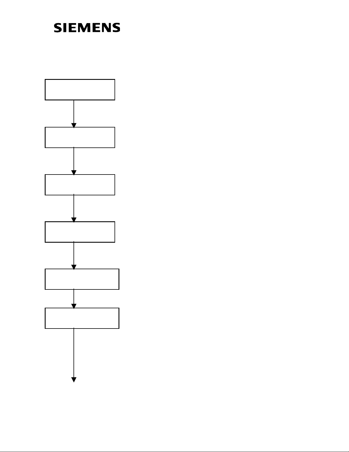
1.4 Drive Control Word
Function Diagrams will be referred to in bra ckets with the ir number. Please refer to
function diagrams in the compendium. Example [Diagram Number]
Assign Digital Inputs
Assign Off2(Coast Stop)
Assign Off3(Quick Stop)
Assign ON/OFF1
Digital Inputs/Outputs:
Binector Assignments for Control
may be made from Digital Inputs
P555, P556 & P557 can be used
to assign Coast to Stop
P558, P559 & P560 can be used
to assign Quick Stop
P554 MUST be assigned to
activate drive. Note:
Acceleration and Deceleration
will be based on ramp generator
[320]
[180] Assign Other
Functionality as
Required
See [190]
Assign Other Control
Functionality as
Required
Version 1.0 March 1, 2000 Page 29
Page 30

Page 30 Version 1.0 March 1, 2000
Page 31

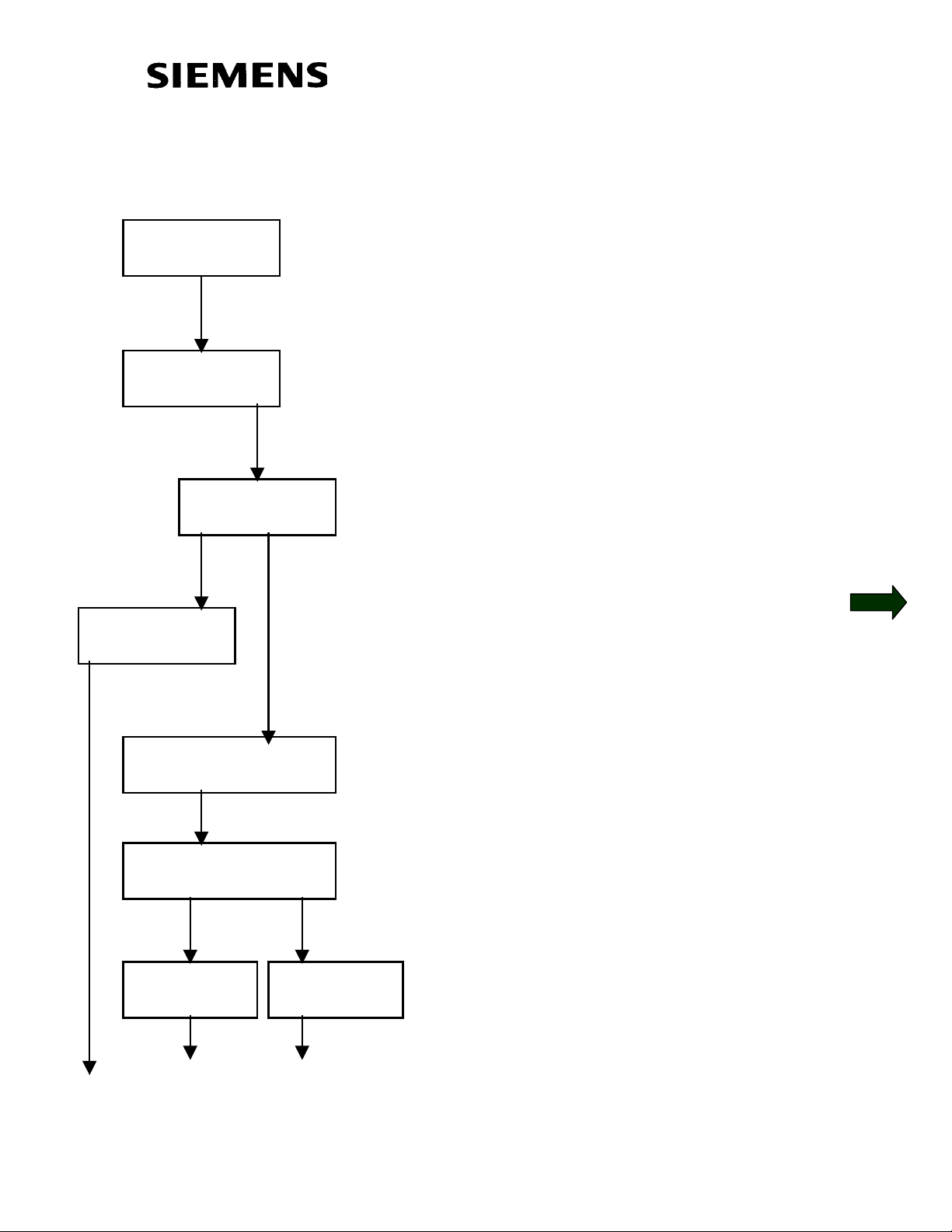
1.5 Communication Board Configuration
P060 = 4
CBx Inserted?
NO
P711 = ?
to
P721.1…5 = ?
SLB Inserted?
NO
P740 = ?
P741 = ?
P742 = ?
P740
= 1
P743 = 0
P745 = ?
YES
YES
P740 = 0
Select “Board Configuration”
Menu
Parameterize CBx Boards
See Function Diagrams
Simolink Address
0: Dispatcher (Master)
>0: Transceiver (Slave)
SLB Telegram Failure Time
SLB Transmit Power
1: Up to 15 m
2: Up to 25 m
3: Up to 40 m
P743=0,
node evaluation.
Enter Number of Channels
Automatic number of
P746 = ?
P749.1…8 = ?
YES
Enter Simolink Cycle Time
correspond to pulse frequency, i.e. =3.2)
Simolink Receive Address =
Node. Channel
(must
CBP Inserted?
NO
P918.1…2 = ?
Input CBP Bus Addresses
Return to Parameter Menu
P060 = 1
Version 1.0 March 1, 2000 Page 31
Page 32

Page 32 Version 1.0 March 1, 2000
Page 33

Section 2:
Parameterization of a Rectifer
Unit
SIMOVERT MASTERDRIVES
6SE70 VC
Vector Control
2.0 Power Section Defintion
2.1 Factory Reset
Basic Start-up
2.2 Rectifier or Regen without auto-transformer
2.3 Regen with auto-transformer
Version 1.0 March 1, 2000 Page 33
Page 34

Page 34 Version 1.0 March 1, 2000
Page 35

2.0 Power Section Definition
Note: Power Section is pre-defined at the factory. Power Section
Definition is required if a new board CUR board is put into the drive or
boards are switched between units with different ratings. CUR cards will
exist Regen Rectifiers and Large Common Rectifiers. The smaller
Common Rectifier will not have parameters. Drive should be defaulted
and re-parameterized after Power Section Definition.
P051 = 3
P052 = 2
P070 = xxx
P052 = 0
P51=3 : Export Mode
P52=2: Function select “Initialization”
Input Code for unit (PWE)
(Refer to the following table)
Return to Parameter Menu
Version 1.0 March 1, 2000 Page 35
Page 36

Unit List
P070: Parameter Value (PWE)
P075: Rated DC Output Current in Amps In[A]
Large Common Rectifier
AC-DC type
3 AC 380V to 460V
PWE Order Number In[A
103 6SE7038-2EH85-0AA0 821.0 105 6SE7041-0EH85-0AA0 1023.0 109 6SE7041-3EK85-0AA0 1333.0 118 6SE7041-8EK85-0AA0 1780.0
3 AC 500V to 575V 101 6SE7037-7FH85-0AA0 774.0
104 6SE7041-0FH85-0AA0 1023.0 107 6SE7041-3FK85-0AA0 1285.0 111 6SE7041-5FK85-0AA0 1464.0 120 6SE7041-8FK85-0AA0 1880.0
3 AC 660V to 690V 102 6SE7037-7HH85-0AA0 774.0
106 6SE7041-0HH85-0AA0 1023.0 108 6SE7041-3HK85-0AA0 1285.0 110 6SE7041-5HK85-0AA0 1464.0 119 6SE7041-8HK85-0AA0 1880.0
Page 36 Version 1.0 March 1, 2000
Page 37
Regenerative Rectifier
AC-DC type
3 AC
380V to 460V
Air Cool
PWE
PWE
Order Number In[A]
Water Cool
14 6SE7022-1EC85-1AA0 21.0
20 6SE7024-1EC85-1AA0 41.0
31 6SE7028-6EC85-1AA0 86.0
39 6SE7031-7EE85-1AA0 173.0
42 6SE7032-2EE85-1AA0 222.0
48 6SE7033-1EE85-1AA0 310.0
51 6SE7033-8EE85-1AA0 375.0
54 6SE7034-6EE85-1AA0 463.0
57 6SE7036-1EE85-1AA0 605.0
63 6SE7038-2EH85-1AA0 821.0
66 6SE7041-0EH85-1AA0 1023.0
73 6SE7041-3EK85-1AA0 1333.0
79 6SE7041-8EK85-1AA0 1780.0
3 AC
500V to 575V
15 6SE7022-7FC85-1AA0 27.0
21 6SE7024-1FC85-1AA0 41.0
28 6SE7027-2FC85-1AA0 72.0
32 6SE7028-8FC85-1AA0 94.0
38 6SE7031-5FE85-1AA0 151.0
44 6SE7032-4FE85-1AA0 235.0
46 6SE7032-7FE85-1AA0 270.0
49 6SE7033-5FE85-1AA0 354.0
52 6SE7034-2FE85-1AA0 420.0
55 6SE7035-4FE85-1AA0 536.0
61 6SE7037-7FH85-1AA0 774.0
67 6SE7041-0FH85-1AA0 1023.0
71 6SE7041-3FK85-1AA0 1285.0
74 6SE7041-5FK85-1AA0 1464.0
80 6SE7041-8FK85-1AA0 1880.0
Version 1.0 March 1, 2000 Page 37
Page 38

Regenerative Rectifier
AC-DC type
3 AC
660V to 690V
Air Cool
PWE
PWE
Order Number In[A]
Water Cool
36 6SE7031-4HE85-1AA0 140.0
43 6SE7032-2HE85-1AA0 222.0
47 6SE7032-7HE85-1AA0 270.0
53 6SE7034-2HE85-1AA0 420.0
56 6SE7035-3HE85-1AA0 536.0
62 6SE7037-7HH85-1AA0 774.0
68 6SE7041-0HH85-1AA0 1023.0
72 6SE7041-3HK85-1AA0 1285.0
75 6SE7041-5HK85-1AA0 1464.0
81 6SE7041-8HK85-1AA0 1880.0
Page 38 Version 1.0 March 1, 2000
Page 39

2.1 Factory Reset
P051 = 3
P052 = 2
P077 = 0
P052 = 0
P51=3 : Export Mode
P52=2: Function select “Initialization”
P077=0 for standard default
P052=0 Return to Parameter Menu
P052 = 1
Version 1.0 March 1, 2000 Page 39
P052=1 Perform Factory Reset
Page 40

Page 40 Version 1.0 March 1, 2000
Page 41

2.2 Basic Start-up (Regenerative Rectifier without
Autotransformer)
P051 = 2
P053 = 6
P052 = 5
P071 = 460
P051=2
Select “Basic Mode Settings”
P053 =6 Access Parameter
P052 = 5
Drive Settings
P071 = Input Rectifier Voltage
Generally = 460 Volt
P320 = 20
P773 = 1.00
Version 1.0 March 1, 2000 Page 41
P320 = 20
Smooth Load Amps, to
prevent input line sags
from effecting the DC BUS
regulator
P773= 1.00
Deadband Converter, to
prevent “toggling” between
Regen and Rectifier
bridges.
Page 42

P052 = 21
P052 = 0
With DC BUS connected to the
COMMON DC BUS of the system, set
P52=21 and provide a start command
at terminal X101, pin #9
The circuit identification test will take
about 10 seconds.
P052=0 Drive back to ready mode.
Standard Commissioning for a Common
Rectifier or a Regenerative Rectifier
without Autotransformer is complete, after
adjusting only 8 parameters.
Page 42 Version 1.0 March 1, 2000
Page 43

Connect External Wiring as connection diagram.
r
Custome
Connection Points
Internal Connections
Step 1: Dry set of contacts between terminals X101, pin#6 and pin#13 for Local/Remote Mode Selection. Jumper if not required.
Step 2: Dry set of contacts between terminals X101, pin#6 and pin#10
for Coast to Stop Selection. Jumper if not required.
Step 3: Dry set of contacts between terminals X101, pin#6 and pin#9 for Source of Main Start/Stop Selection.
Step 4: Dry set of contacts between terminals X101, pin#6 and pin#11
for Source of Fault Reset. Leave open if not required. “P” button on
PMU will be fault reset location if pin#11 is not used.
Step 5: Drive Operating Status is provided by a 24 Vdc signal at
terminals X104 pin#19 with respect to pin#20.
Version 1.0 March 1, 2000 Page 43
Page 44

Page 44 Version 1.0 March 1, 2000
Page 45
2.3 Basic Start-up (Regenerative Rectifier with
Autotransformer)
P051 = 2
P053 = 6
P052 = 5
P071 = 460
P051=2
Select “Basic Mode Settings”
P053 =6 Access Parameter
P052 = 5
Drive Settings
P071 = Input Rectifier Voltage
Generally = 460 Volt
P320 = 20
P773 = 1.00
Version 1.0 March 1, 2000 Page 45
P320 = 20
Smooth Load Amps, to
prevent input line sags
from effecting the DC BUS
regulator
P773= 1.00
Deadband Converter, to
prevent “toggling” between
Regen and Rectifier
bridges.
Page 46

P571 = 0
P318 = 95
P052 = 21
P571=0 Selects Autotransformer
P318 = 95%
Selects percentage of nominal
DC BUS voltage. In cases where
the input line voltage is
dependable a setting of 100% is
permissible.
With DC BUS connected to the
COMMON DC BUS of the system, set
P52=21 and provide a start command
at terminal X101, pin #9
P052 = 0
The circuit identification test will take
about 10 seconds.
P052=0 Drive back to ready mode.
Standard Commissioning for a
Regenerative Rectifier with
Autotransformer is complete, after
adjusting only 10 parameters.
Page 46 Version 1.0 March 1, 2000
Page 47

Section 3:
Simovis Trace Setup Method
SIMOVERT MASTERDRIVES
6SE70 VC
Vector Control
Version 1.0 March 1, 2000 Page 47
Page 48

Page 48 Version 1.0 March 1, 2000
Page 49
3.0 Simovis Trace
N
(
)
Load Simovis from
Vector Control
Documentation CD
Launch Simovis
Option: To speed up your
communication link set the
drive P701 = 38,400 with the
PMU and configure Simovis
for 38,400 communication.
from Desktop Icon
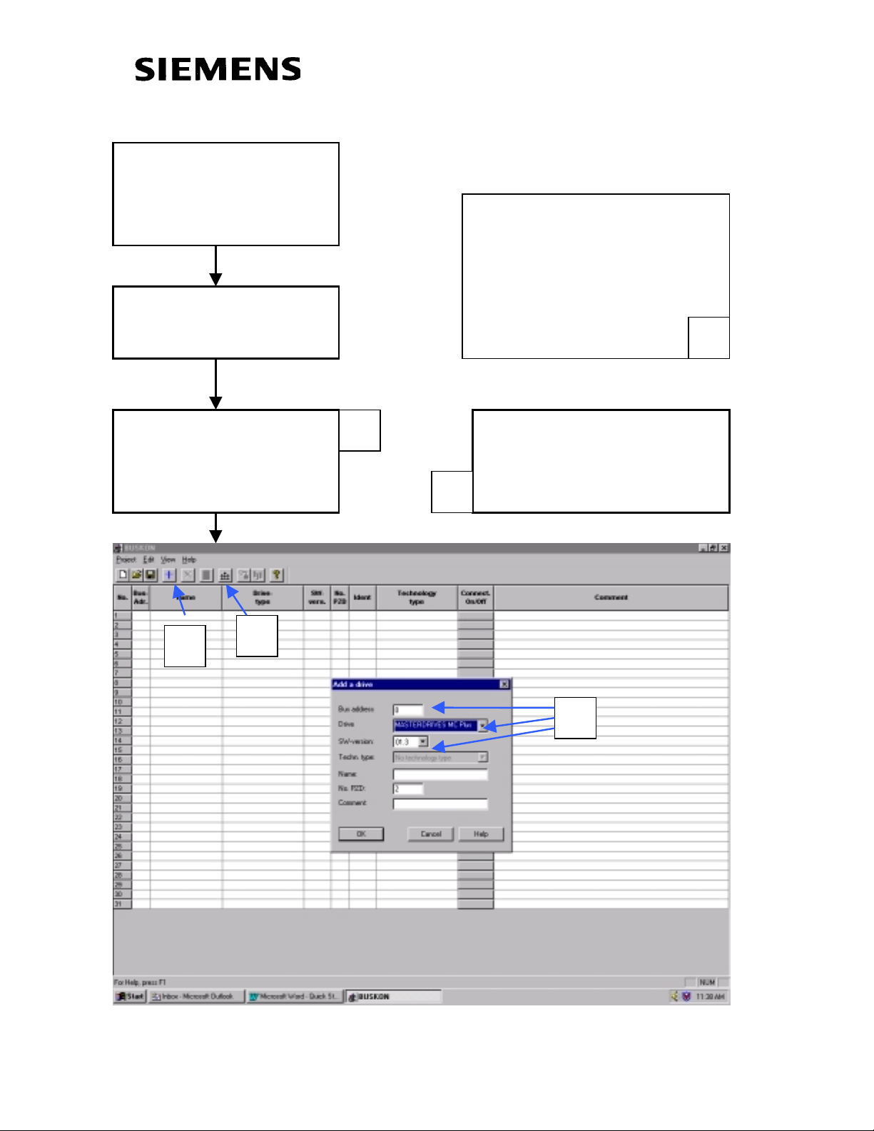
Add a Drive in
Simovis Bus
Configuration
A
C
A
Select USS Bus Address,
Drive and SW Version.
ote: Proper Simovis Cable
B
must be used.
B
C
RS 232
Version 1.0 March 1, 2000 Page 49
Page 50

Double Click Selected
Drive to start Simovis
Window
Verify Drive
Connection
A
Select Trace from
Diagnostics Menu Bar
B
Green Box should be lit up
in the lower left corner
B
A
Page 50 Version 1.0 March 1, 2000
Page 51

Select Record Settings in
the Lower Left Corner
Select Desired Channels
to Record
Set the Record Interval
and Pre-trigger
Select Trigger Channel
A
B
C
D
Each Interval = (4.0 / P340) seconds.
Pre-trigger is in Percentage (%).
To Trigger With a Binector, Select:
Trigger Channel = K431
Trigger Condition “=” “1 Hex”
K431 is the output of a Binector to
Connector Converter that will be
configured on the following page.
Function
Diagram
[720]
B
C
D
A
Version 1.0 March 1, 2000 Page 51
Page 52

Select “Function Block
N
g
pag
Grafics” from the
Parameter Menu Bar
A
To Configure the Trace to
Trigger with a Binector
follow instructions on this
e.
C
Select Function
umber 289
Zoom X 2
(with right Mouse click)
B
Set Trigger Binector in
U076.01
(i.e. U076.01 = 18 Din5)
Activate Block
U952.89 = 4
D
A
C
The block activated by Parameter
U952.89 is selected with 289.
K431 can now be used to
trigger the Trace function
when Binector
asserted hi
(i.e. DIN 5) is
h.
D
Function
Diagram
[720]
B
Page 52 Version 1.0 March 1, 2000
Page 53

Go to the Trace Window
(Diagnostics Menu – Trace)
Verify Record Settings
Start Trace
C
Trigger Trace
Observe Status Message
A
B
D
A
C DB
Version 1.0 March 1, 2000 Page 53
Page 54

Select Data Trace A
N
d
Click Data Set to
make it Active
Scale
Vertical Axis
B
Scale
Horizontal Axis
ote: Background can be change
with right mouse click.
Traces can be saved for reference.
C
Click and Drag
scale to shift it up
and down.
Y▲& Y ▼ to
change Scale
Click and drag “T”
marker to shift
Horizontal Scale.
Move “[ ]” to
change scale
A
B
C
Page 54 Version 1.0 March 1, 2000
Page 55

Section 4:
When to Re-Tune the Drive
SIMOVERT MASTERDRIVES
6SE70 VC
Vector Control
Version 1.0 March 1, 2000 Page 55
Page 56

Page 56 Version 1.0 March 1, 2000
Page 57

4.0 Conditions that would merit re-tuning the drive
Hardware additions made to the drive, such as an output reactor or a
dv/dt filter.
Physical changes to the process, such as the motor being changed
(even if the it is an identical motor, bearing changes and coupling
changes can have an influence on performance), gearbox changes,
length of motor cables changed.
Process changes, such as motor loading, and speed range changes to
name a few. Note that since the type of change described is wideranging manual tuning may be a better alternative. Review the
parameters effected for P115=5.
Software changes, P068, P095, P097, P100(this includes any changes
in P101 through P109), P339, P340, P357.
Exceptions:
• If the carrier frequency of P340 is adjusted in multiples that retuning is not required (ie: 2.5 kHz to 5.0 kHz)
• If P100 is changed from a value of 4 to 5.
Repair or Maintenance, such as replacing either the motor or the CUVC
logic card.
Exceptions:
• If tuning parameters P103, P116, P120, P223, P235, P236, P240 and P471 had been recorded prior to the CUVC card being replaced.
Version 1.0 March 1, 2000 Page 57
 Loading...