

Page 1
W0582
Installation, Operation
and Maintenance Manual
VEC-991-4000B
Peristaltic Pumps
Vector 4000 Series
Models: 4003, 4004, 4006, 4007, 4009, 4010,
& 4014
Model: 4004
1204 Chestnut Avenue, Minneapolis, MN 55403
Tel: (612) 332-5681 Fax: (612) 332-6937
Toll-free fax [US only]: (800) 332-6812
www.vectorpump.com
email: sales@wannereng.com
Model: 4010
Page 2
Vector 4000 Important Precautions
Safety Measures
! CAUTION
Important Precautions
• To avoid personal injury or pump damage, follow all
instructions and safety precautions carefully.
• Don’t exceed the manufacturer’s recommended RPM
or pressure limits.
• Follow all codes and hydraulic recommendations on
installation and operation of the pumping system.
• To prevent vibration, mount thepump andmotor securely
to a rigid, level base.
• For safety and easier servicing, provide adequate work
space around the pump. Allow space to remove the front
co
ver, hose clamps, hose, and drive unit.
W0387
Safety Precautions
General remarks
These safety and installation instructions contain important
information and precautionary notes and must be available to
those operating the pump. Please read them thoroughly prior to
installation, electrical connection and use of the pump. Operating
instructions for components of pumps must be followed.
These safety and installation instructions do not cover local
regulations. Installers and operators must also observe local
regulations during installation and operation.
Each pump must be labeled by the end user to warn of any hazards
that the system process may produce; e.g. corrosive chemicals
or hot process etc.
All personnel involved in the operation, maintenance, inspection
and installation of the pump must be fully qualied to perform
the work. The personnel’s responsibilities, competence, and
supervision must be clearly dened by the operator. To the extent
that if the personnel in question is not already in possession of
the requisite know how, appropriate training and instruction must
be provided. In addition, the operator is responsible for ensuring
that the contents of the operating instructions are fully understood
by all the responsible personnel.
When installing a Vector pump in conjunction with a motor, or motor
and frequency controller, the relevant manuals must be referred
to for electromagnetic compatibility.
All safety instructions in this manual and all relevant local health
and safety regulations must be followed.
Pay attention to the weight of the pump before attempting to lift
either manually or when selecting appropriate lift equipment.
1. Mechanical risk:
Ensure that all protections (cover, sight glass, ventilator hood,
coupling protection) are in place before operating the pump.
Disconnect the electrical supply before any mechanical work,
except during hose replacement.
Hose replacement must be done with the pump cover closed.
While replacing a hose, wear protective gloves and clothes.
Keep hands away from the brackets, suction and discharge
anges.
During pump maintenance, check that lifting points are correctly used.
The frame of the pump must be rmly fastened to the ground.
2. Electrical risk:
Ensure that the electrical installation conforms to the local
standards required; especially regarding ground and thermal
protection.
3. Operational risk:
Check that the materials to be pumped are compatible with the
following:
• Peristaltic pump operation.
• Hose material.
• Lubricant.
• Inserts material.
• Shoe material.
Wanner cannot guaranty the hose lifetime or the material loss
due to a hose burst. It is the operator’s responsibility to prevent
pumped liquid loss with additional hose rupture detectors and
or automatic shut down valves. Check guarantee for further
information.
Ensure that the pump is compatible with the process.
Ensure that the pump suction side pressure is correct.
To avoid hose rupture, make sure that:
• The pump casing is not lled with the pumped material.
• That the suction line is not on load. Otherwise the material
may empty into the pump casing and leak out of the pump.
• That the discharge line is not under pressure. Otherwise the
pumped material may be forced back into the pump casing
and leak out of the pump.
A leakage detector as well as automatic shut down valves are
recommended in order to prevent hose rupture.
When draining the pump following a hose rupture, make sure
the lubricant and pumped material are disposed of properly.
Complete or partial blockage of the positive displacement
pump discharge line can lead to a dangerous high pressure
condition. Before operating the pump, make sure there is no
complete or partial hose blockage.
Before each use, check the direction of rotation of the pump.
While placing the pump under vacuum, mount window screw
using an airtight glue to avoid air leakage.
2
Wanner Engineering, Inc.
United States Instant Information: www.vectorpump.com
(612) 332-5681 Fax (612) 332-6937 VEC-991-4000B
Page 3

Vector 4000 Contents
1 IMPORTANT PRECAUTIONS 2
1.1 Safety Measures 2
1.2 Contents 3
2 HOW TO USE THIS MAINTENANCE MANUAL
2.1 Use of the Pump 4
2.2 Responsibility 4
2.3 User Training and Instruction 4
2.4 Limited Warranty 4
3 DESCRIPTION 5
3.1 Identication 5
3.2 Description of Pump Operation 5
3.3 Pump Parts 6
3.4 Pump Hose 9
3.5 Pump Gearbox 9
3.6 Electrical Motors 9
3.7 Available Options 9
4 I N STA LL AT ION
4.1 Inspection 10
4.2 Installation Planning 10
4.3 Piping 10
4.4 Lifting the Pump 11
5 PUMP STARTUP 11
5.1 Preparations 11
5.2 Startup 11
6 MAINTENANCE 11
6.1 Emptying and Filling of Lubricant 11
6.2 Hose Cleaning 13
6.3 Hose Replacement 13
6.3.1 Removing of the Hose 13
6.3.2 Cleaning of the Pump Casing 15
6.3.3 Reassembly of the Hose 15
6.4 Replacement of Spare Parts 17
6.5 Shoe Shimming 21
6.6 Additional Information 22
6.7 Periodic Check 23
7 STORAGE 23
7.1 Pump Storage 23
7.2 Hose Storage 23
8 TROUBLESHOOTING 24
9 CHARACTERISTICS AND TECHNICAL SPECIFICATIONS 26
9.1 Dimensions 26
9.2 Parts List 29
9.3 Lubrication Table 35
9.4 Shoe Shimming Table 35
9.5 Generated Noise and Temperature 36
Wanner Engineering, Inc.
United States Instant Information: www.vectorpump.com
(612) 332-5681 Fax (612) 332-6937 VEC-991-4000B
3
Page 4
Vector 4000 Introduction
2. HOW TO USE THIS MAINTENANCE MANUAL
This technical manual covers the Vector 4000 Series pumps.
The manual provides instructions on how to install, start, and
maintain the pumps. All persons, installers, and users must
read the manual in its entirety prior to installation and use.
Your local Wanner distributor is also available for additional
information .
For a reply, please include the following information:
- Type of pump
- Pump
Also visit our website www.vectorpump.com for further information.
2.1 USE OF THE PUMP
The pump was dened for specic application. Any other use
which does not comply with this use invalidates the warranty.
Wanner cannot be held responsible for damage or possible
injury incurred during the use of the pump. The pump was designed in accordance with applicable norms and directives. Use
the pump only for applications represented above. If you want
to change your application, rst contact your Wanner distributor.
2.2 RESPONSIBILITY
Wanner will be under no circumstances responsible for damage
or wounds caused by non respect of security directives and
maintenance instructions contained in this manual, or by negligence during the installation, use, service or repair of Wanner
hose pumps. Moreover, additional directives of security can be
necessary according to working conditions or according process. Contact your Wanner distributor if you notice a potential
danger during the use of the pump.
2.4 Limited Warranty
Wanner Engineering, Inc. (“Wanner”) extends to the original
purchaser of equipment supplied or manufactured by Wanner
and bearing its name, a limited one-year warranty from the
date of purchase against defects in material or workmanship,
under normal use and service, and provided the equipment
is installed, operated and maintained in accordance with
instructions supplied by Wanner. Wanner will repair or replace,
at its option, defective parts without charge if: (a) you provide
written notice of any defect within thirty (30) days from the
discovery of the defect; (b) the claim is received by Wanner
before the expiration of the warranty period; and (c) such parts
are returned with transportation charges prepaid to Wanner
Engineering, Inc., 1204 Chestnut Avenue, Minneapolis,
Minnesota 55403. A return goods authorization must be
received prior to the return of the defective part. No allowance
will be made for repairs undertaken without WEI’s written
consent or approval.
2.3 USER TRAINING AND INSTRUCTION
Every person who installs, uses, or performs any operations or
maintenance on the pump must be qualied. The person must
also read and be familiar with this technical manual.
Any temporary personnel must be supervised by skilled users.
The order of operational steps dened in this manual must be
followed. Store this manual next to the pump so that it can be
consulted at any time.
4
Wanner Engineering, Inc.
United States Instant Information: www.vectorpump.com
(612) 332-5681 Fax (612) 332-6937 VEC-991-4000B
Page 5
Vector 4000 Description
3 DESCRIPTION
3.1 Identication
Vector pumps are identied by the nameplate located on
the upper bracket. It includes the type and model number of
the pump. This model number indicates information regarding pump materials, type of the hose, characteristics of the
gearbox, and characteristics of the motor. The gearbox as well
as the motor have their own nameplates on which include the
reduction ratio, power, and electrical voltage.
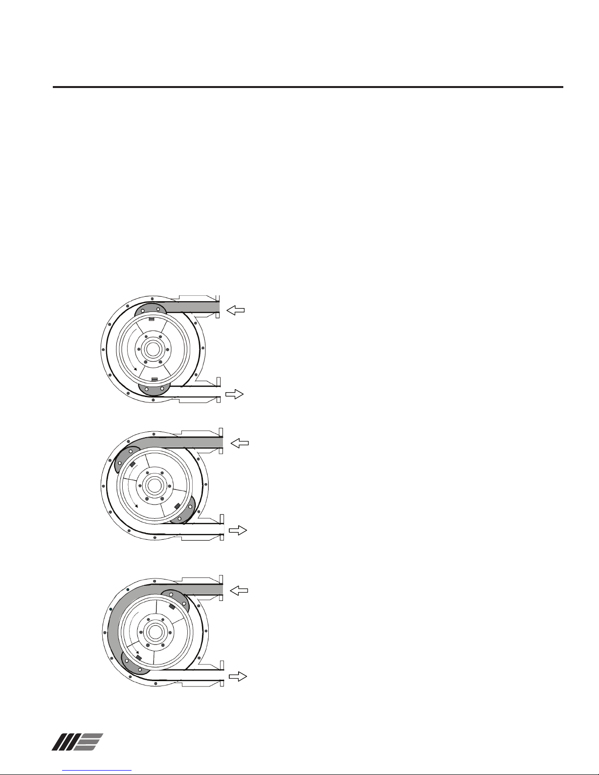
3.2 Description of Pump Operation
PHASE 1
The pump hose is compressed successively by two pressing
shoes assembled on a rotating wheel. The rst shoe, by pressing the walls of the hose, will create a vacuum and suck the
pumped liquid into the hose.
Wanner Engineering, Inc.
PHASE 2
The pumped liquid has now entered the hose. The second
shoe will compress the hose and push the liquid towards the
pump outlet.
PHASE 3
As soon as, at the discharge side, the shoe is detached from
the hose, the other shoe diametrically opposite is already in
compression thus avoiding an internal material leakage. The
material is then successively sucked and pushed due to the
wheel rotation.
United States Instant Information: www.vectorpump.com
(612) 332-5681 Fax (612) 332-6937 VEC-991-4000B
5
Page 6
Vector 4000 Description
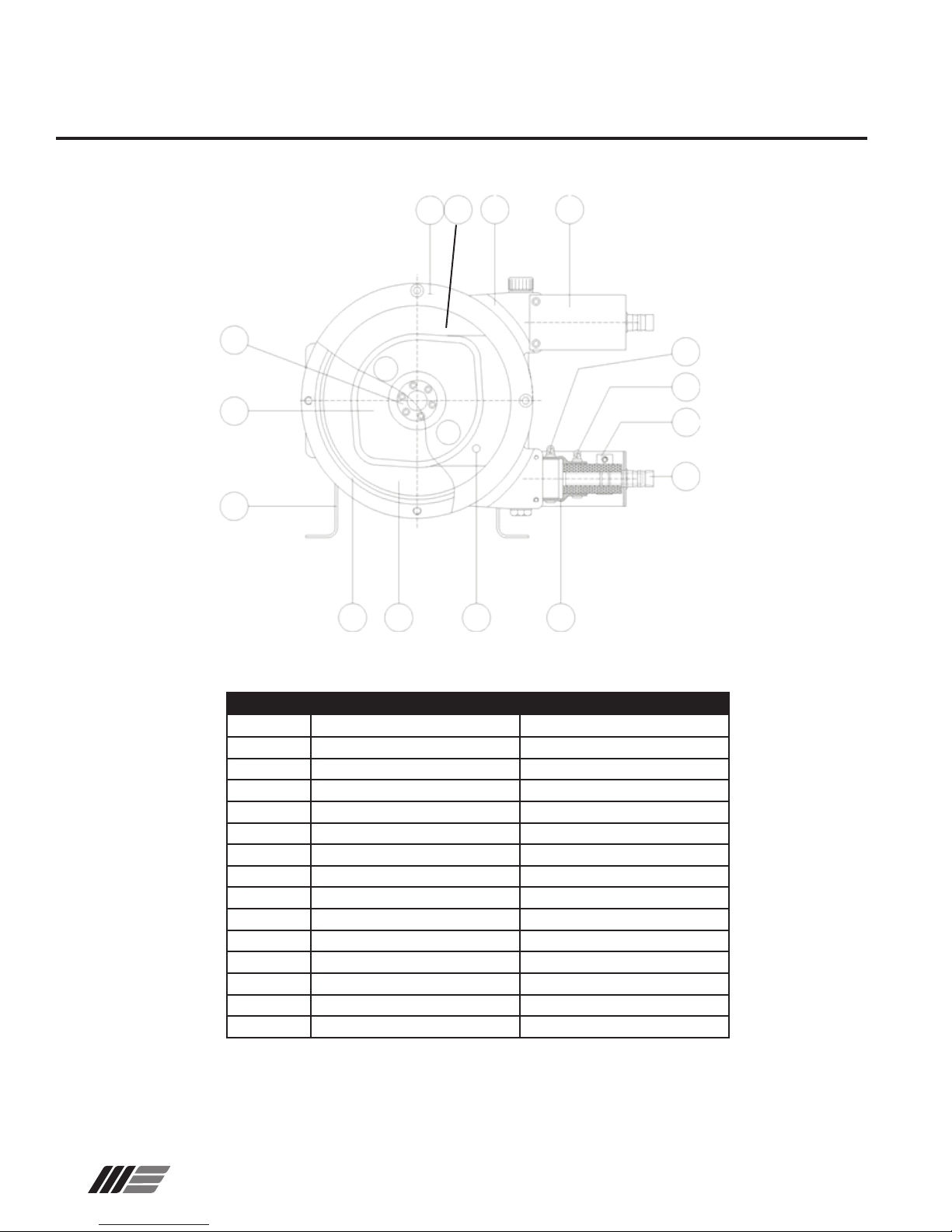
3.3 PUMP PARTS
19
3
21
271 1
18
7
8
9
12
1610
614
VECTOR 4003, 4004
PART NO DESIGNATION 4003, 4004 MATERIAL
1 CASING CAST IRON
2 COVER, TRANSPARENT LEXAN
3 WHEEL CAST IRON
6 SLEEVE EPDM
7 CLAMP ON CASING STAINLESS STEEL
8 CLAMP SLEEVE / HOSE STEEL
9 CLAMP ON HOSE STEEL
10 SEAL COVER NITRILE
12 INSERT STAINLESS STEEL
14 LUBRICANT GLYCERIN BLEND
16 HOSE NR/NBR/EPDM
18 BRACKET ELECTROPLATED STEEL
19 HUB STEEL
21 FRAME ELECTROPLATED STEEL
71 COVER PLATE ELECTROPLATED STEEL
6
Wanner Engineering, Inc.
United States Instant Information: www.vectorpump.com
(612) 332-5681 Fax (612) 332-6937 VEC-991-4000B
Page 7
Vector 4000 Description
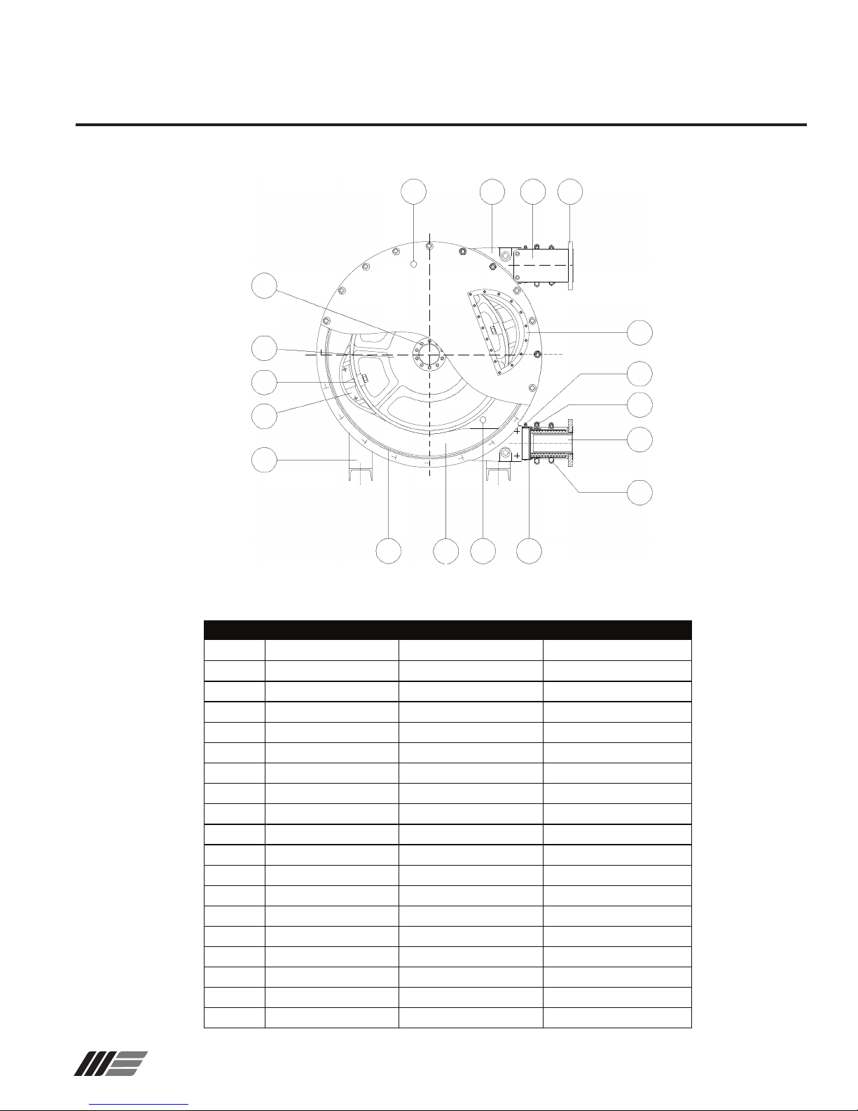
3.3 PUMP PARTS
19
20
3
4
5
21
PART NO DESIGNATION
1
CASING
2
COVER
3
WHEEL
4
SHIM
5
SHOE
6
SLEEVE
7
CLAMP ON CASING
8
CLAMP SLEEVE / HOSE
9
CLAMP ON HOSE
10
SEAL COVER
12
INSERT
14
LUBRICANT
15
SIGHTGLASS
16
HOSE
18
BRACKET
19
HUB
21
FRAME
46
SIGHT GLASS SEAL
47
INLET/OUTLET FLANGE
2
10
VECTOR 4006, 4007, 4009, 4010
16
4006, 4007 MATERIAL
CAST IRON
ELECTROPLATED STEEL
CAST IRON
GALVANIZED STEEL
ALUMINIUM
EPDM
STAINLESS STEEL
STAINLESS STEEL
STAINLESS STEEL
NITRILE
STAINLESS STEEL
GLYCERIN BLEND
LEXAN
NR/NBR/EPDM
ELECTROPLATED STEEL
STEEL
STEEL
NITRILE
STAINLESS STEEL
1
14
47
18
6
4009, 4010 MATERIAL
CAST IRON
STEEL
CAST IRON
GALVANIZED STEEL
ALUMINIUM (4009) / CAST IRON (4010)
EPDM
STEELCK
STAINLESS STEEL
STEEL
NITRILE
STAINLESS STEEL
GLYCERIN BLEND
LEXAN
NR/NBR/EPDM
ELECTROPLATED STEEL
STEEL
STEEL
NITRILE
STAINLESS STEEL
15
7
8
12
9
Wanner Engineering, Inc.
United States Instant Information: www.vectorpump.com
(612) 332-5681 Fax (612) 332-6937 VEC-991-4000B
7
Page 8
Vector 4000 Description
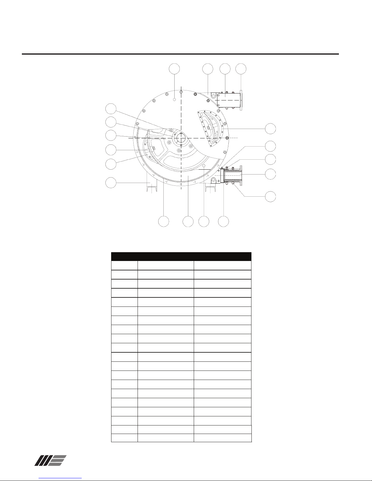
3.3 PUMP PARTS
2
1
18
47
19
20
15
3
4
5
21
7
8
12
9
10 16 14 6
PART NO DESIGNATION
1
CASING
2
COVER
3
WHEEL
4
SHIM
5
SHOE
6
SLEEVE
7
CLAMP ON CASING
8
CLAMP SLEEVE / HOSE
9
CLAMP ON HOSE
10
SEAL COVER
12
INSERT
14
LUBRICANT
15
SIGHT GLASS
16
HOSE
18
BRACKET
19
HUB
20
BOLT ON PLATE
21
FRAME
46
SIGHT GLASS SEAL
47
INLET/OUTLET FLANGE STAINLESS STEEL
VECTOR 4014
4014 MATERIAL
CAST IRON
STEEL
CAST IRON
GALVANIZED STEEL
CAST IRON
EPDM
STAINLESS STEEL
STAINLESS STEEL
STEEL
NITRILE
STAINLESS STEEL
GLYCERIN BLEND
LEXAN
NR/NBR/EPDM
ELECTROPLATED STEEL
STEEL
CAST IRON
STEEL
NITRILE
8
Wanner Engineering, Inc.
United States Instant Information: www.vectorpump.com
(612) 332-5681 Fax (612) 332-6937 VEC-991-4000B
Page 9
Vector 4000 Description
3.4 PUMP HOSE
Wanner hoses are manufactured according to strict specications for the best performance of the pump and to assure optimum hose life. Hoses are available in four materials: Natural
Rubber (NR), perbunan (NBR), EPDM, and Hypalon. The hose
material must be compatible with the liquid pumped. Consult
your Wanner distributor to obtain the correct hose for your use.
Vector 4000 pumps operate in temperatures between + 14°F
and +176°F. Pumps are painted with a 150µ Polyurethane
paint to resist corrosive environments. Pumps are designed for
indoor and outdoor use.
HOSE DIMENSIONS (dimensions in mm)
PUMP INNER ø THICKNESS LENGTH
4003 10 11 570
4004 15 11 830
4006 25 14.5 1090
4007 32 15.5 1300
4009 40 13.5 1500
4010 51 15 1820
4014 80 21.5 2910
3.5 GEARBOX
Gearboxes are sized according to the pump’s radial loads.
Consult the gearbox maintenance manual for the type, quan-
tity, and frequency of oil changes.
3.6 ELECTRICAL MOTORS
The standard motors provided on pumps are TEFC motors and
require a 230/460 VAC, 60Hz, 3Ø voltage source. If the pump
is to be used in an explosive environment, please contact the
factor y.
3.7 AVAILABLE OPTIONS
The following Vector Pump options are available:
- Hose rupture detector.
- Pulsation dampener.
Please contact your Wanner distributor for additional information about these options
Wanner Engineering, Inc.
United States Instant Information: www.vectorpump.com
(612) 332-5681 Fax (612) 332-6937 VEC-991-4000B
9
Page 10
Vector 4000 Installation
W0383A
6 to 8 feet
6 to 8 feet
4 INSTALLATION
4.1 INSPE C T I O N
The pump must be checked upon receipt for any possible
damage or incomplete shipment. Notify Wanner Engineering
of any discrepancies immediately.
Check all boxes or packages containing spare parts or
accessories packed with the pump.
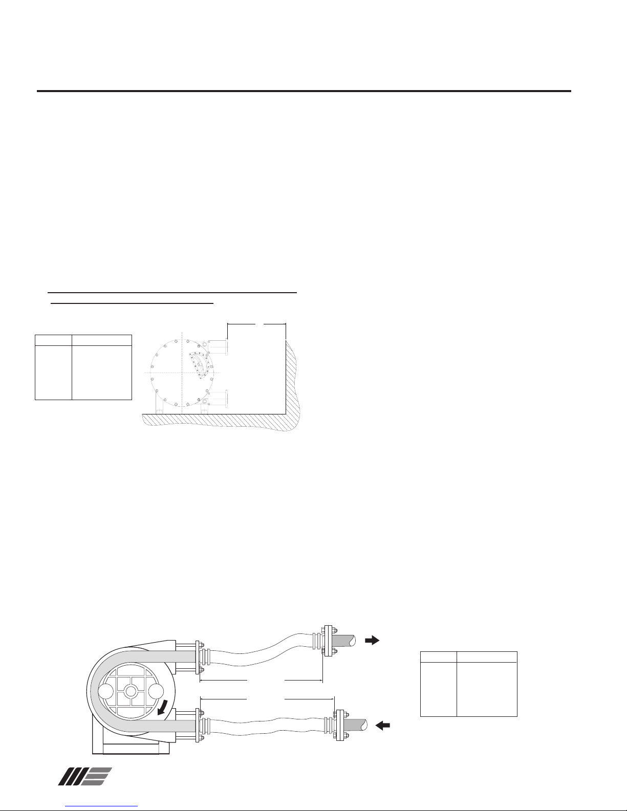
4.2 INSTALLATION PLANNING
Location
1. Locate the pump near the liquid source, so that the suction line
is short and direct.
2. When practical, locate the pump above the level of the liquid; if
the hose fails, the pumpage drains back into the tank.
3. Allow space to remove the front cover, hose, and drive
unit. See Inlet Hose Length Chart (A).
Inlet Hose Length Chart (A)
A
PUMP DISTANCE (A)
4003 1.3 ft
4004 1.6 ft
4006 2.6 ft
4007 3.3 ft
4009 3.9 ft
4010 4.6 ft
4014 6.5 ft
Foundation
The foundation should be suciently rigid and substantial to
absorb any vibration, and to permanently support the base plate
at all points. A concrete foundation, poured on a solid footing of
adequate thickness to support the pumping unit provides the
most satisfactory foundation.
The base plate should be installed in a level position. The size
and location of the base mounting holes are shown on the pump
specication sheets. Use the dimensions provided in the pump
specication data sheets for general piping.
Note: For a detailed description of proper procedures
for grouting base plates, refer to the Hydraulic Institute
Standards.
4.3 PIPING
Inlet piping:
1. Size the inlet line 1.5 or two sizes larger than the pump suction
opening.
2. Suction lines should be as short and direct as possible.
3. See Site Plumbing Figure below. Install 6 to 8 feet of
reinforced exible hose between pump and rigid piping to
absorb vibration, expansion and contraction, and to make
maintenance easier.
Note: The inlet hose must be capable of withstanding a
vacuum. This avoids hose collapse which will restrict
ow.
4. Install an inlet pressure/vacuum gauge on the inlet side of the
pump.
5. To reduce turbulence and resistance, do not use 90° elbows.
If turns are necessary in the suction line use 45° elbows or
long sweeping elbows when required.
6. Install piping supports where necessary to relieve strain on
the inlet line and to minimize vibration.
7. In some cases, a pulsation dampener may be required to
decrease acceleration head and pulsations. Mount dampener
within ten pipe diameters of the pump suction connection. The
closer the better.
Discharge piping:
1. See Site Plumbing Figure below. Install a length, B,
of reinforced flexible hose (one size larger than pump
connection) between pump and rigid piping. This will absorb
vibration, provide for expansion and contraction. It also
creates a reservoir and eases the replacement of the hose.
2. Size the rigid discharge line to be at least the size of the pump
inlet connection.
3. Install piping supports where necessary to relieve strain on
discharge piping and to minimize vibration.
4. Install a pressure gauge in the discharge piping.
5. In some cases, a pulsation dampener may be required
to decrease pulsations. Mount dampener within ten pipe
diameters of the pump discharge connection. The closer the
better.
6. Install a pressure relief valve to protect the pump and piping.
10
Wanner Engineering, Inc.
Site Plumbing Figure
B
B
United States Instant Information: www.vectorpump.com
(612) 332-5681 Fax (612) 332-6937 VEC-991-4000B
PUMP DISTANCE (B)
4003 2 ft
4004 2 ft
4006 2.5 ft
4007 3 ft
4009 4 ft
4010 5 ft
4014 8 ft
Page 11
Vector 4000 Installation and Maintenance
4.4 LIFTING THE PUMP
Pumps are provided with two lift rings tted on the upper part
of the frame. While lifting the pump, do the following:
1. Lift the complete hose pump using the lifting rings plus
additional support on the gearbox and the motor using
suitably rated straps or slings.
2. Never exceed a lift’s upper weight limit. Refer to the Pump
Weight table below to determine the size of lift required.
3. The motorized pump, given its centre of gravity, will tend
to overbalance on the pump head side. Make sure that
the persons are at a security distance of the pump to avoid
any risk of wound.
4. Never raise the pump otherwise than by the pump’s lifting
rings.
5. Never raise the pump by it’s orices nor by it’s brackets.
Pump Weight
Pump 4003 4004 4006 4007 4009 4010 4014
Lb. 55 77 176 287 463 694 2050
5. PUMP STARTUP
5.1 PREPARATIONS
1. Connect the electrical motor in accordance with the local
rules and regulations. Perform this work by qualied
personnel.
2. Make sure that the lubricant level arrives at the level of the
sight glass. Add lubricant if required by the breather
or by the sight glass. See 6.1.
3. Make sure the shimming of the pump is according to the
pump process. See 6.5.
4. Check the direction of rotation of the pump. It is
recommended to install a rotation inverter on the motor
for the hose change.
5. 2 STARTU P
1. Install piping at the inlet and outlet of the pump.
2. Make sure that valves at the inlet and outlet are opened.
3. Start the pump by checking its direction of rotation by the
sight glass.
6. MAINTENANCE
Note: The numbers in parentheses are Reference Numbers
located in the Parts List exploded views of this manual.
6.1 CHANGING LUBRICANT.
Check lubricant level every 1000 hours. Change as follows:
1. Stop the pump
2. Place a tray underneath the drain plug (23)
3. If necessary, install a tap and a drain circuit instead of the
drain plug
4. Make sure tray will hold the quantity of lubricant during
the drainage process. See 9.3 Lubrication Table for quantity.
5. Unscrew the drain plug and drain lubricant
6. Position and tighten drain plug by applying Teon® band
or waterproof paste of close drain tap.
7. Remove sight glass (15) as well as seal (46) and ll the
casing with Wanner lubricant. See 9.3 Lubrication Table for
quantity. Fill with lubricant to the level of the sight glass or
underneath the shaft line. See illustration below.
Note: You can also ll the casing by removing the
breather cap (52) at the back of the pump casing.
8. Check the condition of the seal (replace if necessary).
Reassemble sight glass (or tighten the breather cap).
Maximum lubricant
level
15,46
52
Note: The numbers in parentheses are Reference Numbers
located in the Parts List exploded views of this manual.
Wanner Engineering, Inc.
23
Note: If the pump is mounted with the inlet/outlet posi-
tioned upwards, lubricant drainage is obtained by unscrewing some cover bolts in the lower part.
United States Instant Information: www.vectorpump.com
(612) 332-5681 Fax (612) 332-6937 VEC-991-4000B
11
Page 12

Vector 4000 Maintenance
W0582
6.1 CHANGING LUBRICANT. (Cont’d)
FOR MODELS 4003, 4004:
Unscrew breather plug (52). Place a funnel inside the
breather plug hole and ll the casing with the Wanner lubricant.
See 9.3 Lubrication Table for quantity. Fill lubricant to just
underneath the shaft.
52
12
Wanner Engineering, Inc.
United States Instant Information: www.vectorpump.com
(612) 332-5681 Fax (612) 332-6937 VEC-991-4000B
Page 13

Vector 4000 Maintenance
6.2 HOSE CLEANING
The hose can be cleaned without removing. Use water or
cleaning liquid (check compatibility with hose material). With
Some pumped material requires cleaning after each use to
avoid material hardening in the hose.
CAUTION: Make sure that the cleaning liquid temperature
is the same as the hose material.
6.3 HOSE REPLACEMENT
Note: The numbers in parentheses are Reference Numbers
located in the Parts List exploded views of this manual.
CAUTION: Before any hose change, check the following
points:
1. Skilled personnel are to perform this service and have read
and understand this manual.
2. Close inlet and outlet valves to minimize material loss.
3. Wear clothes that provide protection when using the
pumped material.
4. Observe all safety and environmental rules governing the
use of the pumped material.
6.3.1 HOSE REMOVAL
1. Disconnect and remove suction and discharge piping.
2. Drain lubricant as outlined in Section 6.1.
3. Loosen clamps (8) and (9) at the suction inlet.
Remove insert (12) and ange (47) See Figure 1.
8
9
47
12
Figure 1
FOR MODELS 4003, 4004:
3. Loosen clamps (8) and (9) at suction inlet. Remove
circlips (24) and remove bracket (18) and insert (12). See
Figure 2.
8 9
24
12
18
Figure 2
Wanner Engineering, Inc.
United States Instant Information: www.vectorpump.com
(612) 332-5681 Fax (612) 332-6937 VEC-991-4000B
13
Page 14

Vector 4000 Maintenance
6.3.1 HOSE REMOVAL (Cont’d)
4. -At the discharge outlet, loosen clamps (8) and (9).
-Remove the insert (12) and remove the ange (47) as
well as the brackets (18). See Figure 3.
5. Remove clamps.
9 8
47
FOR MODELS 4003, 4004:
At the pump outlet, loosen clamps (8) and (9).Remove circlips (24)
and dismantle bracket (18). Remove insert (12) and clamps.
See Figure 5.
8
9
12
18
WARNING!
The hose can come out of the pump casing very fast and
cause harm. Ensure that no one is in front of the pump´s
outlets when removing the hose.
WARNING!
Use care when you jog/run the motor to avoid injury.
6. Carefully jog/run motor to expel hose from pump casing
outlet side. See Figure 4.
12
Figure 3
Pump casing
24
18
Figure 5
Figure 4
14
Wanner Engineering, Inc.
United States Instant Information: www.vectorpump.com
(612) 332-5681 Fax (612) 332-6937 VEC-991-4000B
Page 15

Vector 4000 Maintenance
6.3.2 PUMP CASING CLEANING
Note: The numbers in parentheses are Reference Numbers
located in the Parts List exploded views of this manual.
This operation is necessary when a hose burst has caused
material contamination inside the pump casing.
1. Unscrew cover bolt s (33) by leaving two cover bo lt s partly
fastened to the casing. Partially remove the cover (2) from
the casing and x a shackle in one of the cover’s highest bolt
holes (4014 is equipped with a lifting ring). Unfasten the
remaining cover bolts and remove the cover. See Figure 6.
2. Check the state of the cover seal (10) and replace if
necessary.
3. Check the state of wear of the pressing shoes (5) and
replace them if necessary. See 6.4.
CAUTION: A wear of shoes can cause problems to the
pump and provoke abnormal hose lifetime.
4. In the case of a hose burst, it is possible that the shaft seal (26)
and seal ring (27) have been damaged when pumping an
abrasive liquid. See 6.4 and Parts List to replace.
5. Wash the casing with clear water and remove any residue.
6. Dry the pump casing entirely.
7. Replace the cover seal in its groove.
8. Reassemble the pump cover.
6.3.3 REASSEMBLY OF THE HOSE
2,10
6
33
Figure 6
5
47
WARNING! You should never assemble a new hose without a mounted cover.
1. Pre-assemble the ange (47) at the inlet port with two
bracket bolts See Figure 7.
FOR MODELS 4003, 4004:
Temporarily mount the bracket 18 at the inlet port.
2. Clean the new Wanner hose carefully. Slightly coat it with
Wanner lubricant. Slightly lubricate the inside of the
sleeve (6).
18
Figure 7
Wanner Engineering, Inc.
United States Instant Information: www.vectorpump.com
(612) 332-5681 Fax (612) 332-6937 VEC-991-4000B
15
Page 16

Vector 4000 Maintenance
6.3.3 REASSEMBLY OF THE HOSE (Cont’d)
3. Insert hose at the outlet port. See Figure 8.
WARNING!
Use care when you jog/run the motor to avoid injury.
4. Reverse the direction of rotation of the motor.
5. While pushing on the hose, jog/run the motor and check the
direction of rotation.
6. The shoes mounted on the wheel are going to “swallow” the
hose and push it out of the inlet port. Jog the motor to bring
the hose against the ange (47). See Figure 9.
7. Assemble the clamps (8) and (9) on the inlet side. Mount
the insert (12) into the hose. Tighten clamps.
FOR MODELS 4003, 4004
Dismantle the bracket 18. Mount clamps on the hose. Mount
the insert into the hose. Fix bracket (18) and block the insert
with circlips (24). Tighten clamps.
Outlet Port
Figure 8
Note: If you have diculty assembling inserts into the
pump hose, coat them slightly with Wanner lubricant.
Never use another lubricant.
8. Assemble the brackets (18) and pre-assemble ange (47) on
the outlet side with two temporary bolts.
FOR MODELS 4003, 4004
Assemble the brackets at the outlet side.
9. Reverse the direction of rotation of the motor.
WARNING!
Use care when you jog/run the motor to avoid injury.
10. Jog/run the motor to bring the hose against the discharge
ange.
11. Perform step 7 at discharge side.
12. Fill the pump with the necessary quantity of Wanner
lubricant. See 6.1. and 9.3.
13. Take away the temporary ange bolts and x the piping on
both suction and discharge sides.
14. Open the valves at the suction and discharge sides.
15. Check the direction of rotation of the pump. Check for any
possible lubricant leakage by the inserts, sleeves or cover.
18
47
Figure 9
16
Wanner Engineering, Inc.
United States Instant Information: www.vectorpump.com
(612) 332-5681 Fax (612) 332-6937 VEC-991-4000B
Page 17

Vector 4000 Maintenance
6.4 REPLACEMENT OF SPARE PARTS
Note: The numbers in parentheses are Reference Numbers
located in the Parts List exploded views of this manual.
6.4.1 REPLACEMENT OF PUMP SHOES (except 4003 and
4004)
WARNING!
Use care when you jog/run the motor to avoid injury.
1. Jog/run the motor and position one of the shoes in front of
the sight glass.
2. Cut the power supply.
3. Drain the lubricant. See 6.1.
4. Remove the pump cover (2) as well as the cover seal (10).
See Figure 10 and Figure 11.
5. Disassemble the shoe which is not in contact with the hose
and put aside the shims if any. Check that the pin (30) is
still on the wheel (4006, 4007, 4009, 4010).
6. Mount a new shoe on the wheel with shoe bolt (28) and shoe bolt
washer (29). Slide the shims (4) between the shoe and the
wheel before tightening.
CAUTION: Be careful of the position of the shoe with centering pin 30 (4006, 4007, 4009, 4010).
7. Tighten the shoe onto the wheel.
8. Temporarily reassemble the cover with three cover bolts (33)
positioned 120° from each other.
WARNING!
Use care when you jog/run the motor to avoid injury.
9. Jog the motor 180° to bring the second shoe in front of the
sight glass.
10. Remove the cover once again and perform steps 5 thru 7.
11. Reposition the cover and tighten all cover bolts.
2,10
Figure 10
28,29
Wanner Engineering, Inc.
Figure 11
United States Instant Information: www.vectorpump.com
(612) 332-5681 Fax (612) 332-6937 VEC-991-4000B
17
Page 18

Vector 4000 Maintenance
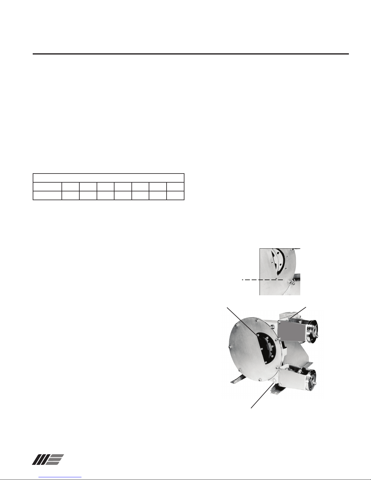
6.4.2 REPLACEMENT OF THE SEAL RING (27) AND THE
SHAFT SEAL (26)
Note: The numbers in parentheses are Reference Numbers
located in the Parts List exploded views of this manual.
Wanner hose pumps are equipped with a leakage channel to
observe wear of the seal ring or the shaft seal. This channel is
at the back of the pump casing underneath the gearbox ange.
It also protects the gearbox seals by leaving the lubricant or
the material to pass freely at the back of the pump casing. See
Figure 12, Figure 13, and Figure 14.
41
72
27
LEAKAGE
CHANNEL
Figure 12
PUMPS 4006, 4007, 4009, 4010
1. Isolate the pump from the power supply.
2. Empty the lubricant and clean out the pump. See 6.1.
3. Remove the pump hose. See 6.3.1.
4. Disassemble the pump cover and remove the cover
seal (10).
5. Disassemble the wheel by unscrewing the hub (19).
6. Remove the wheel of the pump shaft with a suitable lifting
equipment.
7. Support the gear motor with a suitable lifting equipment.
8. Unscrew nuts (41), washers (72) and remove gearbox from
pump casing.
9. Cut out and remove seal sleeve (27) if damaged.
10. Slip on spacer ring (73) if used and glue to the
shaft.
Note: Contact Factory before performing step 11!
11. Position new seal ring (27) against spacer ring or
the gearbox shaft’s shoulder. Fill the key groove with
silicone mastic to ensure correct sealing.
12. Remove the shaft seal (26) with a drift punch.
13. Replace with new shaft seal using a suitable tool
(wooden or plastic cylinder). Check the mounting
position of the seal (opened side turned to the cover).
26
Cylinder Tool
Figure 13
18
Wanner Engineering, Inc.
United States Instant Information: www.vectorpump.com
(612) 332-5681 Fax (612) 332-6937 VEC-991-4000B
Page 19

Vector 4000 Maintenance
14. Mount the gear motor on the casing being careful not to
damage the shaft seal. Tighten nuts (41) and washers (72).
15. Mount the wheel on the pump shaft. Position and space
wheel as indicated by the illustration in Figure 15. Refer
to the Positioning Distances (L) table, depending on the
pump used.
19
LL
Figure 15
Figure 14
Model: 4003 4004 4006 4007 4009 4010 4014
Distance: 4 2.75 5.5 6 5 3 8
Distance (L) in mm (plus or minus 0.5 mm)
Positioning Distances (L)
Wanner Engineering, Inc.
United States Instant Information: www.vectorpump.com
(612) 332-5681 Fax (612) 332-6937 VEC-991-4000B
19
Page 20

Vector 4000 Maintenance
16. Cross tighten the expandible hub (19) with a dynamometric
spanner to the torque gure specied in the Hub Torque
table. Check the wheel position once again. See Figure 16.
Hub Torque TABLE
Torq u e
Spanner
Figure 16
17. Mount the cover seal (10) in its groove and mount the
cover.
18. Mount the pump hose as stated in 6.3.3.
Note: The numbers in parentheses are Reference Numbers
located in the Parts List exploded views of this manual.
1. Steps 1 thru 10. for Vector pumps 4003 and 4010.
2. Disassemble the seal ange (25) and remove the shaft
seal with a screwdriver or a similar tool.
3. Take the new shaft seal (26) between the thumb and index
ngers and form a “gure 8”.Insert seal into its groove. See
Figure 17.
25
PUMP TYPE TORQUE Nm
4003, 4004 12
4006, 4007 13
4009 27
4010 35
4014 11 0
67
26
Figure 17
4. Mount gear motor on pump casing. See 6.4.2., step 13.
5. Replace the O-ring (67) if necessary and reassemble the
seal ange.
6. For pump 4014, perform steps 14 thru 17 as above.
20
Wanner Engineering, Inc.
“gure 8”
United States Instant Information: www.vectorpump.com
(612) 332-5681 Fax (612) 332-6937 VEC-991-4000B
Page 21

Vector 4000 Maintenance
6.5 SHOE SHIMMING (except 4003 and 4004)
Note: The numbers in parentheses are Reference Numbers
located in the Parts List exploded views of this manual.
Note: This paragraph does not apply to pumps 4003, 4004.
CAUTION: The shimming of shoes is an operation which
consists in adding shims under the shoe to stop any internal leakage. An internal leakage considerably reduces
the life time of the hose as well as the ow. As a result,
it is essential to adjust the shoe’s shimming according
to the rotation speed of the pump, the desired discharge
pressure and the liquid viscosity.
WARNING! Never run the pump without the sight glass.
The shoe shimming can be made without disassembling the
hose or the cover. Shims are inserted or removed thru the
sight glass opening as described in the following steps.
See Figure 18 illustrations.
WARNING!
Use care when you jog/run the motor to avoid injury.
37
1. Jog/run the motor and bring a shoe in front of the sight
glass.
2. Cut the power supply of the pump.
3. Unscrew the sight glass bolts (37) and remove taking care in
not damaging the seal.
4. Slightly unscrew the shoe’s fastening bolt(s) and lift the shoe (5)
o the wheel with a screwdriver or a similar tool.
5. You can now either slide in or remove the necessary
number of shims under the shoe.
Note: Consult the shimming table 9.6 to determine the
precise number of shims according to your application.
6. Tighten the shoe bolts (28).
7. Reassemble the sight glass with its seal.
8. Re-connect and jog/run the motor to bring the second shoe
WARNING!
Use care when you jog/run the motor to avoid injury.
in front of the sight glass.
9. Cut the power supply of the pump.
10. Repeat steps 3 thru 7.
Replace the sight glass seal (46) if necessary.
5
Inserting Shims
Wanner Engineering, Inc.
Figure 18
United States Instant Information: www.vectorpump.com
(612) 332-5681 Fax (612) 332-6937 VEC-991-4000B
21
Page 22

Vector 4000 Maintenance
6.6 ADDITIONAL INFORMATION
Note: The numbers in parentheses are Reference Numbers located in the Parts List exploded views of this manual.
6.6.1 MAINTENANCE AND PERIODIC INSPECTIONS TABLE (4003, 4004, 4006, 4007, 4010, and 4014).
1 Pump hose replacement In prevention, change the pump hose
after 90 % of the life time of the rst
hose.
2 Lubricant replacement. At the end of two hose changes or 5000
hours of use. Otherwise, in every hose
break
3 Gearbox oil replacement. Refer to the gearbox maintenance
manual provided with the pump.
4 Replacement of the seal ring (27). In case of presence of lubricant in the
leak channel.
5 Replacement of the shaft seal (26). In case of presence of lubricant in the
leak channel.
6 Replacement of the shaft seal (105)
and (10 6)
7 Replacement of the shoes. If these are worn on the contact
8 Replacement of the cover seal (10). In the case of a leak around the pump
8 Replacement of the sleeves (6). If damaged. Refer to 6.3. Perform steps
9 Replacement of the bearings (103)
and (104)
In case of presence of oil in the leak
channel or at the lip seals.
surface.
cover.
If there are abnormal noises coming
from the bearing case.
See 6.3.
See 6.1. and 9.3.
See 6.4.2.
See 6.4.2.
See 6.4.2. and 6.6.
See 6.4.1.
See 6.3.2.
1 thru 4 of 6.3.1 and change
sleeves. Use care.
See 6.4. and 6.6.
9 Check the lubricant level. Before starting the pump and
periodically during the pump service.
10 Check for lubricant leakage at the
leakage channel.
11 Check the pump casing to dis-
cern possible leakages around the
cover, the sight glass, the anges and
the sleeves.
12 Check for wear on the shoe’s pressing
surface.
13 Check the presence of a gearbox oil
leakage.
14 Check for strange noises coming
from the pump, gearbox and bearing case or abnormal pump casing
temperature.
22
Wanner Engineering, Inc.
Before starting the pump and periodically during the pump service.
Before starting the pump and periodically during the pump service.
At every hose change. See 6.4.
Before starting the pump and periodically during the pump service.
Periodically during the pump service.
United States Instant Information: www.vectorpump.com
(612) 332-5681 Fax (612) 332-6937 VEC-991-4000B
See 6.1.
See 6.4.
See 3.5.
Page 23

Vector 4000 Maintenance and Storage
6.6.2 SETUP
Note: The numbers in parentheses are Reference Numbers
located in the Parts List exploded views of this manual.
Before the setting up the pump, check the following:
1. The pump with its drive and frame must be xed to a solid
base with a slope which does not exceed 5mm for 1m and
must be rmly fastened to this one.
2. The alignment of pump and drive shafts must be made in
accordance with instructions given by the manufacturer of
the coupling. Refer to the specic notice of such material.
To achieve alignment and coupling, use a perfectly straight
ruler to control the misalignment, and a feeler gauge for
angular misalignment. Control four points (top, bottom, left,
right) at each stage of the installation (after setting on
foundations, after xing pipes and after a rst start).
3. Make sure there is enough room around the pump to carry
out maintenance. If that was not the case, envisage
the moving of the pump in a space provided for this
purpose.
4. Make sure the room is adequately ventilated to relieve the
heat generated by the pump. Leave a space behind
the motor ventilator hood so as not to obstruct the air intake.
6.6.3 PUMP STARTING
Perform the procedures outlined in the PUMP STARTUP section 5, before pump operation.
6.7 PERIODIC CHECK
Regularly check the absence of grease coming from the leakage channel or from lip seal (106).
7 STORAGE
7.1 PUMP STORAGE
Store the pump in a sheltered and dry place and ensure that
the storage room temperature is between 68°F and 113°F.
Protect the pump if necessary and block the inlet and outlet
orices:
1. If the pump stays without working more than 1 month, with
draw the hose from the pump or remove one of the shoes
as well as its centering pin and position the wheel
so that the second shoe can be seen threw the sight glass.
For models 4003,4004, position the wheel so that one of the
cam lobes remains submerged in the lubricant.
2. If you can neither remove the hose or one of the shoes,
run the pump 5 minutes a week.
7.2 HOSE STORAGE
Hoses must be stored sheltered from light in a cool place.
CAUTION: Hose performance is reduced after two years,
due to material aging.
6.6.4 BEARING CASE DISMANTLING AND LIP SEAL REPLACEMENT
Perform steps in 6.4.2. Disassemble the bearing case in the
same way as for the gearbox.
1. Remove lip seals (105) and (106) from the bearing
case.
2. Remove circlips (107).
3. Remove shaft with bearings.
4. Disassemble bearings and replace them together with shaft (102)
as needed.
Wanner Engineering, Inc.
United States Instant Information: www.vectorpump.com
(612) 332-5681 Fax (612) 332-6937 VEC-991-4000B
23
Page 24

Vector 4000 Troubleshooting
8 TROUBLESHOOTING
PROBLEM POSSIBLE REASON RESOLUTION
The pump does not work No power supply. Check that the pump power switch is in
the “ON” position.
Check the motor connection.
The pump wheel stalls. Check the hose.
Check that the discharge pressure is not
too high.
Check that the material hasn’t blocked the
hose.
The lubricant level detector has been
activated.
Low capacity or pressure Not enough Shims under shoes. Add the sucient number of shims.
Air leak at the inlet of the pump. Check and tighten pump clamps (if nec-
Valve closed or partly closed at inlet. Open valve.
Wor n hose. Replace hose.
Material too viscous or excessive pump
speed in comparison with the material
viscosity.
Piping blocked or partly blocked at inlet. Unblock piping and ensure good material
Check lubricant level.
Check if the pump hose has burst. Replace.
essary).Check inlet piping seals.
Check with your Wanner distributor.
ow.
24
Wanner Engineering, Inc.
United States Instant Information: www.vectorpump.com
(612) 332-5681 Fax (612) 332-6937 VEC-991-4000B
Page 25

Vector 4000 Troubleshooting
8 TROUBLESHOOTING
PROBLEM POSSIBLE REASON CORRECTION
Hose life is too short. Incompatibility of the hose with the
pumped material.
Discharge pressure too high. Check that the discharge pressure of the
Pump speed too high. Reduce pump speed.
Wrong shimming. Check shimming.
Pumped material temperature too high. Contact your Wanner distributor.
Lubricant leakage around the cover Loose cover bolts. Cover seal wear. Tighten cover bolts. Replace cover seal.
Lubricant leakage in the leakage channel
(underneath the gearbox ange)
Lubricant leakage at the sleeves Loose clamps or damaged sleeve(s). Tighten clamps. Replace sleeves.
Pipe pulsations. Piping not connected correctly. Fix piping connections.
Shaft seal or seal ring wear. Replace.
Process creating abnormal pulsations
due to the pumped material, the speed
of pump, discharge pressure, or the pipe
sizing.
Make sure the compatibility of the hose
with your material and contact your Wanner distributor.
pump does not exceed 15 bars (or 8 bars
for 4003, 4004). Check that the outlet
piping is not blocked up and that all
valves are opened.
Make sure that the security valve works
co rrec tly.
Make sure that the piping friction losses
do not exceed the value requested for an
appropriate functioning of the pump.
Contact your Wanner distributor.
Wanner Engineering, Inc.
United States Instant Information: www.vectorpump.com
(612) 332-5681 Fax (612) 332-6937 VEC-991-4000B
25
Page 26

Vector 4000 Dimensions
9 CHARACTERISTICS AND TECHNICAL SPECIFICATIONS
9.1 VECTOR 4000 PUMP DIMENSIONS: 4003, 4004, 4006, 4007, 4010, 4014 FLANGED GEAR MOTOR and FPSHS series
PUMPS 4003, 4004
M
O
L
N
4 x K
P
I
J
3 LOBES
2 LOBES
H
H
D
Q
Q
F
G
C
E
B
A
Model A B C D E F G H I J
4003 103.5 115 226 95 256 220 240 33.5 260 280
4004 73 193 296 145 322 250 280 51.75 300 330
Model K L M N O P Q
4003 4xø9 - 46.5 34.5 ø16 * 56 81.25
4004 4xø13 - 49 35.5 ø20 * 68.8 124.75
Note: all units in mm.
ALL DIMENSIONS AND TECHNICAL DATA IS SUBJECT TO CHANGE WITHOUT NOTICE
26
Wanner Engineering, Inc.
United States Instant Information: www.vectorpump.com
(612) 332-5681 Fax (612) 332-6937 VEC-991-4000B
Page 27

Vector 4000 Dimensions
B C D E F G H I J
L M N
Q
65 69
83 89
9.1 VECTOR 4000 PUMP DIMENSIONS: 4006, 4007
L D C
M N
O
H
E
H
B
4 x K
P
I F
J
G
Q Q
A
Model
4006
4007
Model
4006
4007
Note: all units in mm.
A
95
122.5
K
4xø13
4xø13
262
330
-
-
355.5
435.5
190
238
416
525.5
O
(ANSI FLANGE)
1in. 150 lb
1.5 in. 150 lb
311
426
61
109
351
476
P
110
157.75
110
157.75
560
770
600
810
Wanner Engineering, Inc.
United States Instant Information: www.vectorpump.com
(612) 332-5681 Fax (612) 332-6937 VEC-991-4000B
27
Page 28

Vector 4000 Dimensions
N
Q
86
B C D E F G H I J
9.1 VECTOR 4000 PUMP DIMENSIONS: 4009, 4010, 4014
L
N
O
M
4xK
P
I
J
D C
Q Q
H
E
H
F
G
B
A
MODEL
4009
4010
4014
MODEL
4009
4010
4014
Note: all units in mm.
A
110
164.5
262
K
4xø19
4xø19
4xø27
430
554
876
M
75
94.5
140.5
400
517.5
803
102
142
28
Wanner Engineering, Inc.
291
360
555
O
(ANSI FLANGE)
1.5 in. 150 lb
2.0 in. 150 lb
3.0 in. 150 lb
616
801.5
1320
340
513
690
P
87
152
210
170
256.5
345
United States Instant Information: www.vectorpump.com
(612) 332-5681 Fax (612) 332-6937 VEC-991-4000B
420
593
830
170
186.5
345
850
950
1300 1400
1050
950
Page 29

Vector 4000 Parts
51 6
41
27
39
7 848 9
16
26 23 52 18 42 21
3
121
42 72
19
10
2
34
33
71 not shown. See 3.3. Vector 4003, 4004 Description.
Vector 4003, 4004
Wanner Engineering, Inc.
United States Instant Information: www.vectorpump.com
(612) 332-5681 Fax (612) 332-6937 VEC-991-4000B
29
Page 30

Vector 4000 Parts
768125 151237
8 9 48
27
22
40
3
74
24 27 14 139 26
A
12
23
47
16
10
2
46
15
38
37
35 3633
B
DETAIL B
19
30
28
29
5
DETAIL A
4
Vector 4006, 4007
30
Wanner Engineering, Inc.
United States Instant Information: www.vectorpump.com
(612) 332-5681 Fax (612) 332-6937 VEC-991-4000B
Page 31

Vector 4000 Parts
768125 151237
8 9 48
27
22
40
3
74
24 27 14 139 26
A
12
23
47
16
10
2
46
15
38
37
35 3633
B
DETAIL B
19
30
28
29
5
DETAIL A
4
Vector 4009, 4010
Wanner Engineering, Inc.
United States Instant Information: www.vectorpump.com
(612) 332-5681 Fax (612) 332-6937 VEC-991-4000B
31
Page 32

Vector 4000 Parts
63 78 64
Lifting ring on
4014 cover.
32
37 72
37
22
31
19
48
42 72
26 25 43
70*
67
6 7 8 9
B
14136 21
A
12 10 2 46 51 83 7316
47
2315 25 18
3435 36 33
C
DETAIL C
20
3
30**
DETAIL A
28
29
4
5
DETAIL B
Vector 4014
32
Wanner Engineering, Inc.
United States Instant Information: www.vectorpump.com
(612) 332-5681 Fax (612) 332-6937 VEC-991-4000B
Page 33

Vector 4000 Parts List
X X X
X X X
X X X
X
X
X X X
X X X
X X
X X X
X X X
X X X
X X X
X
X X X
X X X
X X X
X X X
X X X
X
X X X
X X X
X
X
X
X X X
X
X
X X X
X X X
X X X
X X
X
X
9.2 VECTOR 4000 Parts List
F.
Ref # DESCRIPTION 4003 4004 4014
1
CASING
2
COVER, TRANSPARENT
3
WHEEL
4
SHIM
5
SHOE
6
SLEEVE
7
CLAMP SLEEVE
8
CLAMP ON SLEEVE / HOSE
9
CLAMP ON HOSE
10
COVER SEAL
12
INSERT
14
LUBRICANT
15
SIGHT GLASS
16
HOSE
18
BRACKET
19
HUB
20
BOLT ON PLATE
21
FRAME
22
LIFT RING
23
OIL PLUG
24
CIRCLIPS
25
SEAL FLANGE
26
SHAFT SEAL
27
SEAL SLEEVE
28
SHOE BOLT
29
SHOE BOLT WASHER
30
SHOE CENTERING PIN
31
BOLT ON PLATE SCREW
32
NUT FOR 31
33
COVER BOLT
34
COVER BOLT WASHER
35
COVER STUD
36
NUT FOR 35
37
SIGHT GLASS BOLT
38
WASHER FOR 37
39
FRAME BOLT
40
WASHER FOR 39
41
GEARBOX STUD
42
NUT FOR 41
43
SEAL FLANGE BOLT
46
SIGHT GLASS SEAL
47
INLET & OULET FLANGE
DESIGNATION
FPSH 05
FPSH10
X
X
X
X
X
X
X
X
X
X
X
X
X
X
X
X
X
X
X
X
X
X
FPSH15
FPSH20
X
4006 to
FPSH25 TO
4007
FPSH40
X
X
X
X
X
X
X
X
X
X
4009 to
FPSHX40 TO
4010
X
X
X
FPSH80
X
X
X
X
X
X
X
X
X
X
X
X
X
X
X
X
X
X
X
X
X
X
X
X
X
X
X
X
X
X
X
X
X
X
X
X
X
X
X
X
Wanner Engineering, Inc.
United States Instant Information: www.vectorpump.com
(612) 332-5681 Fax (612) 332-6937 VEC-991-4000B
33
Page 34

9
CLAMP ON HOSE
X X X X
10
COVER SEAL
X
X X X
12
INSERT
X
X X X
14
LUBRICANT
X
X X X
15
SIGHT GLASS
X
X
16
HOSE
X
X X X
18
BRACKET
X
X X X
19
HUB
X
X X X
20
BOLT ON PLATE
21
FRAME
X
X X X
22
LIFT RING
23
OIL PLUG
X
X X X
24
CIRCLIPS
X
X
25
SEAL FLANGE
26
SHAFT SEAL
X
X X X
27
SEAL SLEEVE
X
X X X
28
SHOE BOLT
X
X
29
SHOE BOLT WASHER
X
X
30
SHOE CENTERING PIN
X
X
31
BOLT ON PLATE SCREW
32
NUT FOR 31
33
COVER BOLT
X
X X X
34
COVER BOLT WASHER
X
35
COVER STUD
X
36
NUT FOR 35
X
37
SIGHT GLASS BOLT
X X
38
WASHER FOR 37
X
X
39
FRAME BOLT
X
X X X
40
WASHER FOR 39
X
X X X
41
GEARBOX STUD
X
X X X
42
NUT FOR 41
X
X X
43
SEAL FLANGE BOLT
46
SIGHT GLASS SEAL
X
X
47
INLET & OULET FLANGE
X
X
X X X
X X
X X X
X
X X X
X X
X X X
X X X
X X X
X X X
X X X
X X X
X X X
X X X
X X X
X
X
X
X
X
X
X
X
X
X
X
X
X
X
X
X
X
X
X
X
X
X
X
X
X
X
X
X
X
X
X
X
Vector 4000 Parts List (Cont’d)
9.2 VECTOR 4000 Parts List (Cont’d)
F.
Ref # DESCRIPTION 4003 4004 4014
48 BRACKET BOLT
49 BRACKET BOLT WASHER
51 90° BEND
52 BREATHER PLUG
63
101 BEARING CASE
102 SHAFT
103 ROLLAR BEARING
104 BALL BEARING
105 LIP SEAL
106 LIP SEAL
107 CIRCLIPS
108 GREASER
109 SHAFT KEY
LIFT RING ON COVER
64
BOLT FOR 63
67
O RING FOR SEAL FLANGE
70
GEARBOX CENTRING FLANGE
71
COVER PLATE
72
WASHER for 41
73
SPACER RING
74
PLUG
110 SHAFT KEY
DESIGNATION
FPSH 05
FPSH10
X
X
X
X
X
X
X
X
X
X
X
X
X
FPSH15
FPSH20
X
X
4006 to
FPSH25 TO
FPSH40
4007
X X
4009 to
FPSHX40 TO
4010
FPSH80
X
X
X
X
X
X
X
X
X
X
X
X
X
X
X
X
X
X
X
X
34
Wanner Engineering, Inc.
United States Instant Information: www.vectorpump.com
(612) 332-5681 Fax (612) 332-6937 VEC-991-4000B
Page 35

Vector 4000 Lubrication and Shoe Shimming
0
2
3
4
3
0
2
3
0 to 45 4
3
0
2
1
3
2
4
3
9.3 LUBRICATION TABLE
9
The table indicates the quantity of lubricant necessary for every pump size.The table indicates the quantity of lubricant
necessary for every pump size. Employ only Vector lubricant for Vector hose pumps. Refer to 6.2 for
lubricant emptying and filing.
QUANTITY OF LUBRICANT (LITRES)
QUANTITY OF LUBRICANT (LITRES)
.4 SHOE SHIMMING TABLE
Refer to 6.5 to remove or add shims. The table below points out the necessary number of shims under every
shoe according to the speed, pressure and the temperature of the product. Respect these indications scrupulously
to optimize the hose life and to avoid a possible deterioration of the internal parts.
For temperatures over 140°F, withdraw one shim in comparison with the table below.
For viscosities over 3000cP or concentrations exceeding 300g / l, withdraw one shim in comparison with the table below.
For a suction lift higher than 4 metres, add one shim to the following figures.
CAUTION: Every shoe must include the same number of shims (0.5mm).
PUMPS
PUMPS
4003
(QUARTS)
(QUARTS) 42
0.4
4014
.42 .85 1.5 2.4 6.3 9.5
40
4004
0.8
4006
1.4
4007
2.3
4009
6
4010
9
PUMP TYPE 4006
Pressure bar (psi) Speed - Rpm
∆P ≤ 5 (72.5)
5 (72.5) ≤ ∆P ≤ 7.5 (108.75)
7.5 (108.75) ≤ ∆P ≤ 10 (145)
10 (145) ≤ ∆P ≤ 15 (217.5) 10 (145) ≤ ∆P ≤ 15 (217.5)
PUMP TYPE 4009
Pressure bar (psi) Speed - Rpm
∆P ≤ 5 (72.5)
5 (72.5) ≤ ∆P ≤ 7.5 (108.75)
7.5 (108.75) ≤ ∆P ≤ 10 (145)
10 (145) ≤ ∆P ≤ 15 (217.5)
Wanner Engineering, Inc.
0 to 40
40 to 160
0 to 40
40 to 125
0 to 40
40 to 105
0 to 40
40 to 90
0 to 55
55 to 120
0 to 55
55 to 95
0 to 55
55 to 75
0 to 55
55 to 60
Number of
Number of
shims
0
1
2
shims
0
Pressure bar (psi) Speed - Rpm
∆P ≤ 5 (72.5)
5 (72.5) ≤ ∆P ≤ 7.5 (108.75)
7.5 (108.75) ≤ ∆P ≤ 10 (145)
PUMP TYPE 4007
0 to 40
40 to 140
0 to 45
45 to 140
0 to 45
45 to 110
45 to 80
Number of
shims
0
1
2
United States Instant Information: www.vectorpump.com
(612) 332-5681 Fax (612) 332-6937 VEC-991-4000B
35
Page 36

Vector 4000 Shoe Shimming
0
2
3
4
0
2
3
4
TEMPERATURE
The cover and the pump casing can become very hot due to the friction on the hose and liquid temperature. If
you need to limit the pump temperature, please contact your Wanner distributor.
9.4 SHOE SHIMMING TABLE
PUMP TYPE 4010
Pressure bar (psi) Speed - Rpm
0 to 30
30 to 100
0 to 30
30 to 65
0 to 30
30 to 50
0 to 30
30 to 42
∆P ≤ 5 (72.5)
5 (72.5) ≤ ∆P ≤ 7.5 (108.75)
7.5 (108.75) ≤ ∆P ≤ 10 (145)
10 (145) ≤ ∆P ≤ 15 (217.5)
Number of
shims
0
1
2
3
Pressure bar (psi) Speed - Rpm
∆P ≤ 5 (72.5)
5 (72.5) ≤ ∆P ≤ 7.5 (108.75)
7.5 (108.75) ≤ ∆P ≤ 10 (145)
10 (145) ≤ ∆P ≤ 15 (217.5)
PUMP TYPE 4014
0 to 20
20 to 60
0 to 20
20 to 47
0 to 20
20 to 37
0 to 20
20 to 31
Number of
shims
0
1
2
3
9.5 GENERATED NOISE AND TEMPERATURE
NOISE
The Wanner Pumps do not generate more than 60dB during their operation.
1204 Chestnut Avenue, Minneapolis, MN 55403
Tel: (612) 332-5681 Fax: (612) 332-6937
Toll-free fax [US only]: (800) 332-6812
www.vectorpump.com
email: sales@wannereng.com
36
© 2016 Wanner Engineering, Inc. Printed in USA
VEC-991-4000B 12/2016, Revised 5/2017
 Loading...