

Page 1
225 Watt
Power Inverter
Vehicle Power System
Converts DC Vehicle Power
to 115 Volt AC Household Power
VEC034B
USER’S MANUAL
& WARRANTY INFORMATION
IMPORTANT SAFETY INFORMATION, SAVE THESE INSTRUCTIONS
TO REDUCE THE RISK OF INJURY, USER MUST READ AND UNDERSTAND
THIS INSTRUCTIONAL MANUAL. THIS MANUAL CONTAINS IMPORTANT
INFORMATION REGARDING THE OPERATION AND WARRANTY OF THIS
PRODUCT. PLEASE RETAIN FOR FUTURE REFERENCE.
8
Fault Protection Code and Troubleshooting Guide
INVERTER POWER SWITCH TURNED ON
SPECIFICATIONS
Output Connection: North American standard outlets
Output Voltage: Approx. 115 volts AC, RMS 60 Hz
Output Current: 6.5 amps max.
Output Waveform: Modified Sine Wave
Input Voltage: 12.8 volts DC
Low Voltage Alarm
and Shutdown: < 10.7 volts DC
No Load Input Current: 0.4 amps max.
Input Fuses: Internal
Input Cables: Battery clip cables
Additional Protection: Overload, overvoltage, overheating
Trouble/Indication Possible Cause Suggested Remedy
No AC output — Fault LED
lit
DC input is below
10.7 volts
Recharge or replace the
battery.
Excessive appliance
load
Reset unit by turning OFF,
then back ON.
Inverter hot
Disconnect load from
inverter. Operate inverter
without load for a few
minutes. Reconnect load.
No AC output — Power
LED not lit
Bad connection or
wiring
Tighten all DC connections.
Fault LED lights Low battery voltage
Recharge battery. Remove
load from inverter while
recharging battery.
Motorized power tool will
not operate
Excessive start-up load
If appliance does not start,
appliance is drawing too
much voltage and will not
work with this inverter.
Motorized power tool
does not operate at
correct speed
Purely inductive load
Make the load not purely
inductive (i.e., operate an
incandescent lamp at the
same time as power tool).
Television/radio
interference
Snow in picture,
“buzzing” sound
Keep inverter and antenna
distant from each other.
Use shielded antenna.
Connect antenna to
amplifier.
VEC034B_ManualEN_021406 2/17/06 10:06 AM Page 8
Page 2

2. Battery chargers that have a warning label stating that dangerous voltages are present at the
battery terminals.
The majority of portable appliances do not have this problem. Most portable appliances use separate
transformers or chargers that plug into AC receptacles to supply a low DC or AC voltage output to the
appliance. If the appliance label states that the charger or adapter produces a low DC or AC voltage
output (30 volts or less), there should be no problem powering that charger or adapter.
Some fluorescent lamps may not operate properly with this type of inverter. If the bulb appears to be too
bright, or fails to light, do not use the lamp with this inverter.
Some fans with synchronous motors may slightly increase in speed (RPM) when powered by the inverter.
This is not harmful to the fan or to the inverter.
Important Cable Information
Substantial power loss and reduced battery operating time result from inverters installed with cables that
are not able to supply full power. Symptoms of low battery power can result from cables that are either
excessively long or an insufficient gauge. Marine installations are also subjected to vibration and stresses
that exceed those of other mobile installations. Therefore, the installer/operator should be especially
aware of the requirements to maintain secure, tight, water-resistant electrical connections and to provide
for strain relief for DC cables and appliance wiring. Cable insulation must be the appropriate type for
the environment.
Read All Instructions Before Using This Power Inverter!
SAVE THESE INSTRUCTIONS
IMPORT
ANT SAFETY INSTRUCTIONS
WARNINGS
TO REDUCE THE RISK OF FIRE, ELECTRIC SHOCK, EXPLOSION OR INJURY:
• Disconnect inverter before attempting any maintenance or cleaning. Turning off
controls will not reduce the risk of electric shock.
• NEVER connect to AC distribution wiring.
• Remove appliance plug from outlet strip or turn off inverter before working on the
appliance. Multiple outlet power strips with switches and circuit breakers only
interrupt power to the "hot" receptacle terminals. The "neutral" terminals remain
powered with respect to the "ground" terminals.
• Do not open — there are no user-serviceable parts inside. Return to manufacturer or
take to a qualified service technician when service or repair is required. Incorrect
reassembly may result in a risk of electric shock or fire.
• DO NOT make any electrical connections or disconnections in areas designated as
IGNITION PROTECTED. This inverter is NOT approved for ignition protected areas.
• Do not install in compartments containing batteries or flammable materials. This
equipment employs components that tend to produce arcs or sparks.
• Use this unit in properly ventilated areas ONLY.
• Do not insert foreign objects into the outlets.
• Do not expose the unit to liquids, including water, rain or snow.
• Do not attempt to install or operate this unit while operating a motor vehicle.
• This is not a toy — keep away from children.
FOR USAGE ABOVE 80 WATTS:
• Use battery clips ONLY.
• DO NOT use the DC accessor y plug or the fuse will open.
CAUTIONS
• Always inspect battery supply connections and cables to ensure they are tight and that cable insulation
is not damaged.
• Do not use with positive ground electrical systems.* Reverse polarity connection will result in a blown
fuse and may cause permanent damage to the inverter and will void warranty.
*Most modern automobiles, RVs, trucks and boats are negative ground and can be used with this inverter.
• Grounding the Neutral will cause the inverter to shut down. Do not operate this inverter if it is wet. Do
not install in engine compartment — install in a well ventilated area.
• This inverter has not been not tested for use with medical devices.
BATTERY PRECAUTIONS
• Someone capable of being of assistance should be within the range of your voice or near enough to
come to your aid when you work on or near a lead-acid battery.
• Have fresh soap and water nearby. If battery acid contacts skin or clothing, immediately wash with
soap and water. If acid enters eye, flood the eye with cold running water for 10 minutes and
immediately seek medical attention.
• NEVER smoke or allow a spark or flame in the vicinity of the battery.
• Remove personal metal items, such as rings, bracelets, necklaces and watches when working with a
lead-acid battery. These conduct electricity. A lead-acid battery can produce a short circuit current
high enough to cause a severe burn.
APPLIANCE PRECAUTIONS
NEVER plug in battery chargers for cordless power tools if the charger carries a warning that dangerous
voltages are present at the battery terminals.
NEVER plug small appliances directly into the inverter outlets to recharge nickel-cadmium batteries.
Always use the charger provided with the appliance.
Certain chargers for small nickel-cadmium batteries can be damaged if plugged into the inverters. DO
NOT use inverters with the following two types of equipment.
1. Small, battery-operated appliances such as flashlights, cordless razors and toothbrushes that can
be plugged directly into an AC receptacle to recharge.
VEC034B_ManualEN_021406 2/17/06 10:06 AM Page ii
Page 3

TABLE OF CONTENTS
Introduction . . . . . . . . . . . . . . . . . . . . . . . . . . . . . . . . . . . . . . . . . . . . . . . . . . . 1
Controls, Indicators and Connectors . . . . . . . . . . . . . . . . . . . . . . . . . . . . . . . . . . 2
How This Inverter Works . . . . . . . . . . . . . . . . . . . . . . . . . . . . . . . . . . . . . . . . . . 2
Principle of Operation . . . . . . . . . . . . . . . . . . . . . . . . . . . . . . . . . . . . . . . . . . 2
The Power Inverter Output Waveform . . . . . . . . . . . . . . . . . . . . . . . . . . . . . . . 3
Protective Features of the Inverter . . . . . . . . . . . . . . . . . . . . . . . . . . . . . . . . . . . . 3
Installation and Operating Instructions . . . . . . . . . . . . . . . . . . . . . . . . . . . . . . . . 4
Power Source Requirements . . . . . . . . . . . . . . . . . . . . . . . . . . . . . . . . . . . . . . 4
Connection to a Power Source . . . . . . . . . . . . . . . . . . . . . . . . . . . . . . . . . . . . 4
Connection to Load . . . . . . . . . . . . . . . . . . . . . . . . . . . . . . . . . . . . . . . . . . . 5
Placement of the Inverter . . . . . . . . . . . . . . . . . . . . . . . . . . . . . . . . . . . . . . . . 5
Operating Tips . . . . . . . . . . . . . . . . . . . . . . . . . . . . . . . . . . . . . . . . . . . . . . . 6
Care and Maintenance . . . . . . . . . . . . . . . . . . . . . . . . . . . . . . . . . . . . . . . . . . 7
Storage . . . . . . . . . . . . . . . . . . . . . . . . . . . . . . . . . . . . . . . . . . . . . . . . . . . . 7
Maintenance . . . . . . . . . . . . . . . . . . . . . . . . . . . . . . . . . . . . . . . . . . . . . . . . 7
Fuse Replacement . . . . . . . . . . . . . . . . . . . . . . . . . . . . . . . . . . . . . . . . . . . . . 7
Troubleshooting . . . . . . . . . . . . . . . . . . . . . . . . . . . . . . . . . . . . . . . . . . . . . . . . 7
Common Audio/Visual Problems . . . . . . . . . . . . . . . . . . . . . . . . . . . . . . . . . . 7
Fault Protection Code and Troubleshooting Guide . . . . . . . . . . . . . . . . . . . . . . 8
Specifications . . . . . . . . . . . . . . . . . . . . . . . . . . . . . . . . . . . . . . . . . . . . . . . . . 8
INTRODUCTION
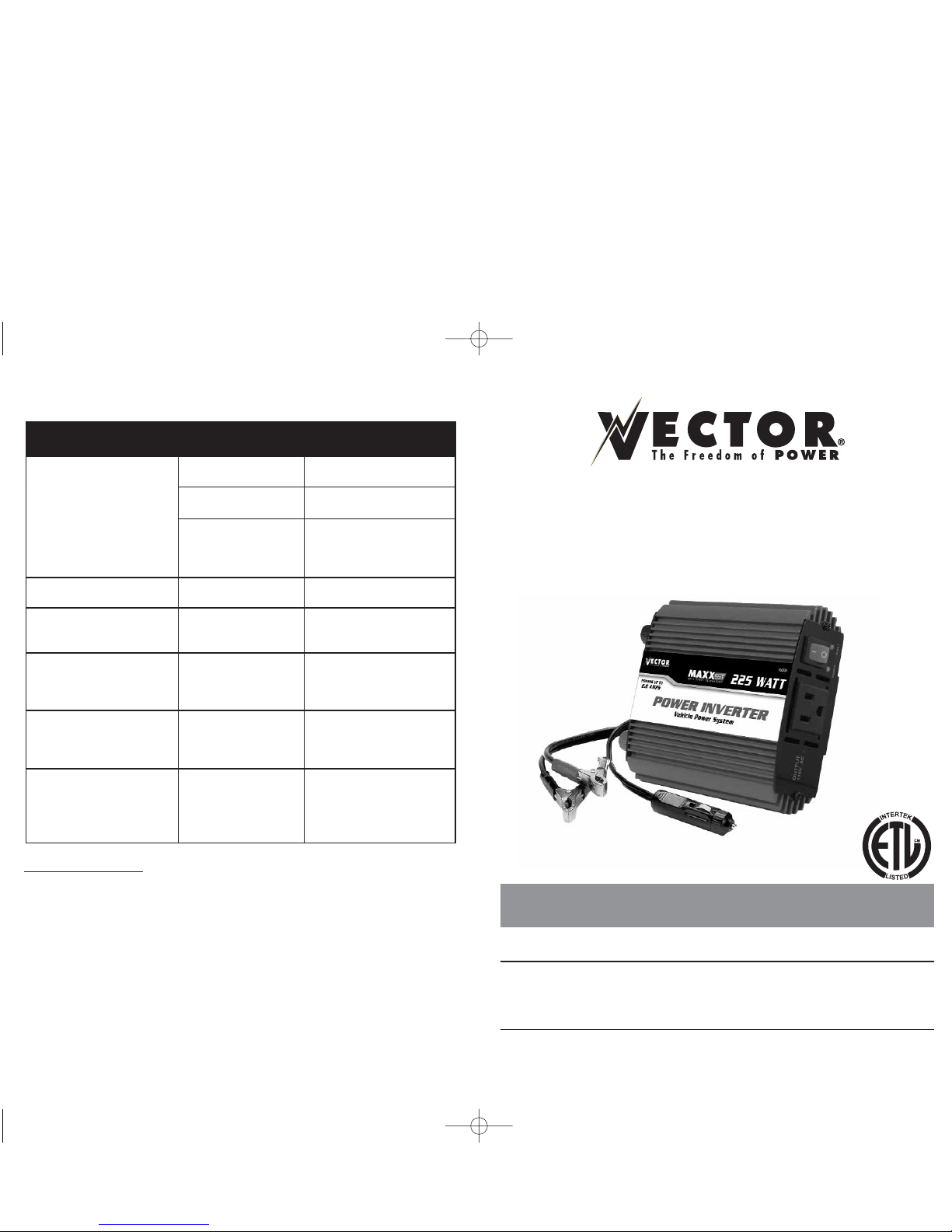
Your new
VEC034B 225 Watt Power Inverter V ehicle Power System
is one
in a series of the most advanced DC to AC inverters available. With proper care and
appropriate usage, it will give you years of dependable service in your car, truck, RV
or boat.
The
VEC034B
supplies 225 watts of continuous power, in the form of a standard
North American household outlet that is ready to deliver 115 volt AC power
whenever and wherever you need it! The heavy-duty inverter has enough power to
run most household or electronic appliances. It also comes equipped with battery
clips to handle higher amperage/load applications, such as: power tools, stereo
amplifiers, vacuums, etc. Added safety features include automatic shutdown and a
low battery alarm to prevent damage to your battery.
This Vector Power Inverter is configured with the latest Soft Start Technology (SST).
Before introduction of Soft-Start, high start-up currents from large inductive loads could
shut down the inverter. Soft Start improves inverter operation. Three major features
incorporated in SST include: First, gradual voltage ramp-up during inverter start-up.
This eliminates failed cold starts under load. Second, output that momentarily dips in
voltage and quickly recovers to allow large motorized loads to start. This eliminates
almost all shutdowns from momentary overloads. Last, the inverter needs to be turned
Page 4

3
This type of waveform is suitable for most AC loads, including linear and switching
power supplies used in electronic equipment, transformers, and motors.
The modified sine wave produced by the Power Inverter has an RMS (root mean
square) voltage of 115 volts, which is the same as standard household power. Most
AC voltmeters (both digital and analog) are sensitive to the average value of the
waveform rather than the RMS value. They are calibrated for RMS voltage under the
assumption that the waveform measured will be a pure sine wave. These meters will
not read the RMS voltage of a modified sine wave correctly. They will read about 20
to 30 volts low when measuring the output of the inverter. For accurate measurement
of the output voltage of this unit, use a true RMS reading voltmeter such as a Fluke
179, Fluke 79 III series, Beckman 4410, or Triplett 4200.
Modified Sine Wave and Sine Wave Comparison
PROTECTIVE FEATURES OF THE INVERTER
The Power Inverter monitors the following potentially hazardous conditions:
Low Battery Voltage —
This condition is not harmful to the inverter, but could damage the
power source. An alarm will sound and the Inverter automatically shuts down when input
voltage drops below 10.7 volts. When the condition is corrected, the inverter will
auomatically restart.
Over Voltage Protection —
The Power Inverter will automatically shutdown when the
input voltage exceeds 15.0 volts DC.
Overload Protection —
The unit will automatically shut down when the continuous
draw exceeds the 225 watts. Reduce the load and manually reset using the inverter’s
ON/OFF Power Switch.
Over Temperature Protection —
If the temperature inside the Power Inverter reaches
150°F, the unit will automatically shut down. Allow the unit to cool for at least 15
minutes before restarting after a heat-related shutdown. Unplug the unit while cooling.
If the Fault LED lights when the battery is fully charged, follow the steps outlined in the
“Troubleshooting” section of this User’s Manual. The Fault LED will light if there is an
excessive voltage drop between the battery and the inverter.
Note:
Reverse polarity or short circuit condition may cause external or internal fuses
to open and may cause irreversible damage to the Power Inverter. Take extra
care to ensure a proper polarity hook-up.
INSTALLATION AND OPERATING INSTRUCTIONS
Power Source Requirements
The power source must provide a nominal voltage of 12.8 volts DC and must be able
to supply the necessary current to operate the load. The power source may be a
battery or a well-regulated DC power supply. To obtain a rough estimate of the current
(in amperes) the power source must deliver, simply divide the power consumption of
the load (in watts AC) by 10.
Example: If a load is rated at 225 watts AC, the power source must be able to deliver:
225 divided by 10 = 22.5 amperes.
2
CONTROLS, INDICATORS AND CONNECTORS
Figure 1
details the front panel, featuring the unit’s 115 volt AC Outlet, ON/OFF
Power Switch and two LED indicators. The green LED indicates power and proper
operation of the inverter and the red LED indicates inverter shutdown from an overload or over-temperature fault. In addition to turning the unit ON and OFF, the
ON/OFF Power Switch can be used to force reset of the inverter circuits.
Power is supplied through a standard North American outlet that can accommodate
either two- or three-pin AC plugs.
Figure 1 Front Panel
Figure 2
shows the back panel of the inverter, where the DC Power Connections and
high speed cooling fan are located.
Figure 2 Back Panel
HOW THIS INVERTER WORKS
The power inverter converts low voltage DC (direct current) from a battery or other
power source to standard 115 volt AC (alternating current) household power.
Principle of Operation
The inverter converts power in two stages. The first stage is a DC to DC conversion
process that raises the low voltage DC at the inverter input to 145 volts DC. The
second stage is the actual inverter stage that converts the high voltage DC current into
115 volts, 60 Hz AC current.
The DC-to-DC converter stage uses modern high frequency power conversion
techniques that have replaced the bulky transformers found in less technologicallyadvanced models. The inverter stage uses advanced power MOSFET transistors in a
full bridge configuration. This ensures excellent overload capacity.
The Power Inverter Output Waveform
The AC output waveform of the Power Inverter is known as “modified sine wave.” It
is a waveform that has characteristics similar to the sine wave shape of utility power.
12VDC to
145VDC
CONVERSION
145VDC to
115VAC
CONVERSION
Internal
Fuses
115VAC, 60Hz
to AC appliances
12VDC
Input
AC
Outlet
HIGH SPEED COOLING FAN
POSITIVE DC POWER
CONNECTION
NEGATIVE DC POWER
CONNECTION
INVERTER ON/OFF
POWER SWITCH
POWER LED
INDICATOR
FAULT LED
INDICATOR
115 VOLT AC
OUTLET
VEC034B_ManualEN_021406 2/17/06 10:06 AM Page 2
Page 5

5
3. Install a fuse holder or breaker close to the POSITIVE (+) terminal of the DC source
(battery).
4. Connect a length of wire on one side of the fuse holder or circuit breaker.
Connect the other end of the wire to the POSITIVE (+) terminal of the inverter.
5. Connect a length of wire between the inverter’s NEGATIVE (–) terminal and the
DC power source NEGATIVE (–-) terminal.
6. Connect a short length of wire to the other terminal of the fuse holder or circuit
breaker. Mark it “POSITIVE” or “+”.
7. Connect the free end of the fuse or breaker wire to the POSITIVE (+) terminal of
the DC power source (battery).
8. Test the inverter by turning it on and plugging in a 100 watt lamp or equipment.
9. If the inverter is not operating properly, then refer to the “T roubleshooting” section
of this manual.
CAUTIONS
•Loose connectors may cause overheated wires and melted
insulation.
• Check to make sure you have not reversed the polarity. Damage due
to reversed polarity is not covered by our warranty.
Connection To Load
The Power Inverter is equipped with a standard North American three-prong type
outlet. Plug the cord from the equipment you wish to operate into the AC outlet. Make
sure the load requirement of your equipment does not exceed 250 watts.
The Power Inverter is engineered to be connected directly to standard electrical and
electronic equipment in the manner described above. Do not connect the Power
Inverter to household or RV AC distribution wiring. Do not connect the Power Inverter
to any AC load circuit in which the neutral conductor is connected to ground (earth)
or to the NEGATIVE of the DC (batter y) source.
CAUTION – Rechargeable Devices
Certain rechargeable devices do not operate well from a modified sine
wave inverter. They only operate pr operly from a standard household
outlet which provides a pure sine wave. Therefore, Vector
recommends that these types of devices be operated from a standard
household outlet only, not from the inverter.
This problem does not occur with the majority of battery-operated
devices. Most of these devices use a separate charger or transformer
that is plugged into an AC outlet. This inverter is easily capable of
operating most chargers and transformers.
Placement of the Inverter
For best operating results, the inverter should be placed on a flat surface, such as the
ground, car floor or seat, or other solid surface. A power cord has been provided for
easy positioning of the inverter. The inverter should only be operated in locations that
meet the following criteria:
DRY – Do not allow water and/or other liquids to come into contact with the inverter.
4
CAUTION
• The Power Inverter must be connected only to batteries with a
nominal output voltage of 12 volts. The unit will not operate from a
6 volt battery and will sustain permanent damage if connected to a
24 volt battery.
• Reverse polarity connection will result in a blown fuse and may
cause permanent damage to the inverter.
Connection to a Power Source
The Power Inverter comes equipped with a DC accessory outlet plug and battery clip
cables for connection to a power source.
Connecting to a Power Source Using the Accessory Outlet Plug
The DC accessory outlet plug is suitable for operating the inverter at power outputs up
to 80 watts. The connectors on the DC Accessory Outlet Plug are clearly marked
POSITIVE (+) and NEGATIVE (–). Attach them to the appropriate post on the back of
the inverter and secure by screwing on the connector caps.
Connect the inverter to a power source by inserting the plug end of the DC Accessory
Outlet Plug firmly into the DC accessory outlet of a vehicle or other functioning 12 volt
DC power source.
CAUTIONS
• When operating above 80 watts, do not use the 12 Volt DC
Accessory Outlet Plug. Use the provided cables or direct hardwiring.
• Do not use with positive ground electrical systems.
Notes:
Most vehicle accessory outlet circuits have fuses rated at 15 to 20 amps or
greater. To operate at full power, either use the battery clip cable (supplied)
or directly wire to the power source with user-supplied wire and fuse. The
majority of modern automobiles, RVs and trucks are negative ground.
Some vehicles require that the ignition be switched to the accessory position
to power the accessory outlet.
Connecting to a Power Source Using the Provided Cables
Use the provided cables and connect the Power Inverter directly to the 12 volt power
source as follows:
1. Make sure the Power Inverter power is turned OFF and that no flammable fumes
are present in the installation area.
2. Connect the RED cable to the RED post marked (+) on the back of the inverter.
Connect the battery clip to the POSITIVE ter minal of the batter y.
3. Connect the BLACK cable to the BLACK post marked (–) on the back of the
inverter. Connect the battery clip to the NEGATIVE terminal of the battery.
4. Make sure that all connections between battery clips and terminals are secure.
Direct Hardwiring to Power Source
Use #14 AWG wire if the inverter to power source connection is 4 feet or less. For
longer cable lengths use #10 AWG wire. In either case, protect the positive (+) wire
from shorts by installing a 50 amp fuse or circuit breaker close to the DC power
source (battery) terminal.
1. Check to be sure the inverter’s power switch is turned OFF and that no flammable
fumes are present.
2. Identify the POSITIVE (+) and NEGA TIVE (–) DC power source (battery) terminals.
VEC034B_ManualEN_021406 2/17/06 10:06 AM Page 4
Page 6

7
CARE AND MAINTENANCE
Storage
1. Ideal storage temperature range is 50-68°F (10-20°C).
2. Store and use the inverter in a cool, dry place with adequate ventilation.
3. Avoid locations that are exposed to heating units, radiators, direct sunlight or
excessive humidity or dampness.
Maintenance
This unit contains no user-serviceable parts. It is recommended that the unit be
returned to manufacturer for service (see the Warranty for repair/replacement policy
and contact information).
Fuse Replacement
This power inverter is equipped with multiple internal fuses. Normally, these fuses will
not blow unless there is a serious problem inside the unit. Internal fuses are
replaceable; however, only electronically knowledgeable people should attempt fuse
replacement. If the unit is damaged during fuse replacement, the warranty may be
voided. Vector recommends contacting Technical Support for guidance. Call toll free:
(866) 584-5504.
TROUBLESHOOTING
Common Audio/Visual Problems
“Buzzing” sound in audio systems
Some inexpensive stereo systems and “boom boxes” emit a buzzing sound from their
speakers when operated from the Power Inverter. This occurs because the power
supply in the electronic device does not adequately filter the modified sine wave
produced by the inverter. The only solution to this problem is to use a higher quality
sound system that incorporates a higher quality power amplified supply.
Television Interference
The Inverter is shielded to minimize interference with TV signals. However, in some
instances, interference may still be visible, particularly with weak TV signals. Try the
following corrective measures:
• Position the inverter as far as possible from the television, the antenna and the
antenna cables. Use an extension cable, if necessary.
• Adjust the orientation of the inverter, the antenna cables and the TV power cord to
minimize interference.
• Make sure that the antenna feeding the television provides an adequate (“snow
free”) signal and that high quality, shielded antenna cable is used.
6
COOL – Ambient air temperature should be between 30˚F (–1˚C) non-condensing
and 105˚F (40˚C). Do not place the inverter on or near a heating vent or any piece
of equipment that is generating heat above room temperature. Keep the inverter
away from direct sunlight, if at all possible.
VENTILATED – Keep the area surrounding the inverter clear to ensure free air
circulation around the unit. Do not place items on or over the inverter during
operation. A fan is helpful if the inverter is operating at maximum power outputs for
extended periods of time. The unit will restart after it cools.
SAFE – Do not use the inverter near flammable materials or in any locations that may
accumulate flammable fumes or gases.
Operating Tips
Rated Versus Actual Current Draw of Equipment
Most electrical tools, appliances and audio/video equipment have labels that
indicate the power consumption in amps or watts. Be sure the power consumption of
the item you wish to operate is rated at 225 watts or less. (If the power consumption
is rated in amps AC, multiply by the AC volts (115) to determine the wattage).
The inverter has overload protection, so it is safe to try to operate equipment rated at
225 watts or less. The inverter will shut down if it is overloaded.
Resistive loads are the easiest for the inverter to operate. However, large resistive
loads, such as electric stoves or heaters usually require more wattage than this inverter
can deliver on a continuous basis. Inductive loads, such as TVs and stereos require
more current to operate than do resistive loads of the same wattage rating.
Induction motors, as well as some televisions, may require two to six times their
wattage rating to start up. The most demanding in this category are those that start
under load, such as compressors and pumps.
Testing is the only definitive way to determine whether a specific load can be started
and how long it can run.
CAUTION
This inverter will not operate high wattage appliances or equipment
that produces heat, such as hair dryers, microwave items, or toasters.
Battery Operating Time
With a typical vehicle battery, a minimum operating time of 2 to 3 hours can be
expected. In most instances, 5 to 10 hours of operating time is achievable. However,
Vector recommends that the operator start the vehicle every half hour to recharge the
battery system. This will guard against any unexpected shut-down of the equipment
and will ensure that there is always sufficient battery capacity to start the vehicle’s
engine. The inverter’s Fault LED will light when DC voltage drops below 11.0 volts.
The inverter may be used whether or not the vehicle’s engine is running. However , the
inverter may not operate while the engine is starting since the battery voltage can
drop substantially during cranking.
The inverter draws less than 0.6 ampere from the battery when it is not supplying
power to a load and ON/OFF Switch is in ON position. In most instances, the
inverter can be left connected to the battery when not in use since it draws so little
current. However, if the vehicle is to remain unused for several days, disconnect the
inverter from the battery.
VEC034B_ManualEN_021406 2/17/06 10:06 AM Page 6
 Loading...