

Page 1
W0454
W0453
Installation and
Operation Manual
VEC-991-2400A
Peris ta lt ic Pum ps
Vector 2000 Series
Models: 2002, 2003, 2004, 2005, 2006, 2007
Models: 2002, 2003, 2004
WANNER ENGINEERING, INC.
1204 Chestnut Avenue, Minneapolis, MN 55403
TEL: (612) 332 - 56 81 FAX: (612) 332- 69 37
TOLL-FREE FAX [US only]: (800) 332-6812
www.vectorpump.com
email: sales@wannereng.com
Models: 2005, 2006, 2007
Page 2

Vector Series Installation
! CAUTION
Important Precautions
• To avoid personal injury or pump damage, follow all
instructions and safety precautions c arefully.
• Don’t exceed the manufact urer’s recommended RPM
or pressure limits.
• Follow all codes and hydraulic recommendations on
installation and operation of the pumping system.
• To prevent vibration, mount the pump and motor securely
to a rigid, level base.
• For safety and easier servicing, provide adequate work
space around the pump. Allow space to remove the front
cover, hose clamps, hose, and drive unit.
W0387
Contents
Important Precautions ............................................ 2
Principles of Operation ........................................... 2
Installation Planning ...............................................2
Pump Test and Installation ..................................... 3
Before Initial Start-Up .............................................3
Maintenance ..........................................................4
Troubleshooting ......................................................4
Service
Models 2002, 2003, 2004, 2005 ....................... 4
Models 2006, 2007 ............................................ 6
Parts List Identification
Models 2002, 2003, 2004 .................................7
Models 2005, 2006, 2007 .................................8
Limited Warranty
Wanner Engineering, Inc. extends to the original purchaser
of equipment manufactured by it and bearing its name, a
limited one-year warranty from the date of purchase against
defects in material or workmanship, provided that the
equipment is installed and operated in accordance with the
recommendations and instructions of Wanner Engineering,
Inc. Wanner Engineering, Inc. will repair or replace, at its
option, defective parts without charge if such parts are
returned with transportation charges prepaid to Wanner
Engineering, Inc., 1204 Chestnut Avenue, Minneapolis,
Minnesota 55403.
This warranty does not cover:
1. The electric motors (if any), which are covered by
the separate warranties of the manufacturers of these
components.
2. Normal wear and/or damage caused by or related to
abrasion, corrosion, abuse, negligence, accident, faulty
installation or tampering in a manner which impairs normal
operation.
3. Transportation costs.
This limited warranty is exclusive, and is in lieu of any
other warranties (express or implied) including warranty of
merchantability or warranty of fitness for a particular purpose
and of any nonc ontractual liabilities including product
liabilities based on negligence or strict liability. Every form
of liability for direct, special, incidental or consequential
damages or loss is expressly excluded and denied.
2
Wanner Engineering, Inc.
Principle of Operation
Two rollers, mounted on a rotor, alternately compress a thickwalled hose in a patented concentric guide. As they rotate, they
push the liquid in the hose from the suction to the discharge
side. The subsequent opening of the hose, after a roller passes,
creates a vacuum on the suction side — resulting in continuous
pumping.
Installation Planning
Inlet Piping
• Size the inlet line one or two sizes larger than pump suction
opening.
• Suction lines should be as short and direct as possible.
• Size the suction line so that the velocity will not exceed
1 – 3 ft/sec.
Velocity =
Pipe I.D.
• Install a 3 ft. to 4 ft. flexible hose between pump and hard
piping to absorb vibrations, expansions, or contractions.
• Install an inlet pressure/vacuum gauge on the inlet side of
the pump.
• To reduce turbulence and resistance, do not use 90° elbows.
If turns are necessary in the suction line use 45° elbows or
long sweeping elbows when required.
• Install piping supports where necessary to relieve strain on
the inlet line and to minimize vibration.
• In extreme cases, a pulsation dampener may be required to
decrease acceleration head.
Discharge Piping
• Size the discharge line to at least the size of the pump inlet
connection.
• Between the pump and hard piping, install flexible a hose
long enough to reduce pulsations (typically 3 ft. to 4 ft.).
• Install a pressure gauge in the discharge piping.
• In extreme cases, a pulsation dampener may be required to
absorb excessive pulsation (caused by high pump speed and
long discharge lines).
United States Instant Information: www.vectorpump.com
(612) 332-5681 Fax (612) 332-6937 VEC-991-2400A
0.408 x GPM
Page 3
Vector Series Installation
W0455
Pressure
Rollers
W0456
DISCHARGE
INLET
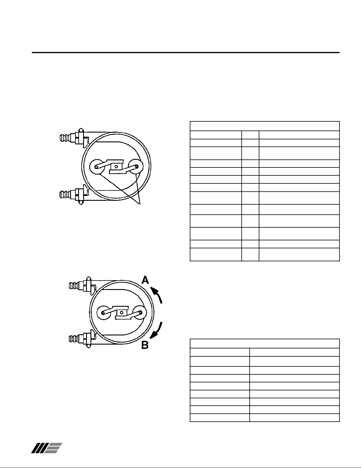
Pump Test and Installation
Before you install the pump in the system, set the direction of
pump rotation and the position of the pressure rollers:
1. Remove front cover from pump (four screws).
2. See Figure 1. For easier adjustment, check that pressure
rollers are in position shown (one roller compressing middle
of hose, and one roller free).
Note: Model 2006 and 2007 pumps use a dif ferent rotor
assembly than the one shown.
Figure 1
3. Connect incoming power supply to motor (refer to motor
manufacturer’s instructions).
4. See Figure 2. Run pump and check direction of rotation,
“A” or “B” as shown. All pumps must rotate in direction “A“
(counterclockwise). To reverse rotation, exchange two of
three wires that connect incoming power to motor.
Before Initial Start-Up
Before you pump fluid through the system, be sure that:
1. All shutoff valves are open.
2. All connections are tightly secured.
3. See Hose Identification Table. Hose material is compatible
with fluid being pumped, and hose design matches duty cycle
and discharge pressures.
Hose Identification
Extruded Code Description
Hypalon HE Black color, shinny smooth surface
Neoprene PE Flat black c olor, rough surface, rubber
Varprene VE Cream color, smooth surface
Silicone SE Rus t color, smooth surface
®
Pharmed
Fiber Braided
Hypalon HF Black color, yellow stripe, double
EPDM EF Black color, white stripe, double braided
Natural Rubber NF Black color, green stripe, double
Natural Rubber MF Black color, no stripes, thick double
Nitrile Rubber BF Black color, white inner hose
Nitrile Rubber - Oil Rated OF Black color, HBRF-HY-K stamped on
4. See Material Operating Temperatures Table. Temperature of
fluid pumped is within operating temperature range of hose
material installed in pump. Hose material can be identified by
5th and 6th digit of pump model number. E.g. 2007-NF-BB-D2,
where ‘NF’ designates natural rubber.
CAUTION: Contact factory when pumping a fluid that is
within 15˚ F of the maximum hose temperature. Take safety
precautions to insure hot pumpage does not harm operators
if a hose leaks.
smell
FE Cream color, Pharmed® name on hose
braided
braided (standard duty)
braids (heav y duty)
hose
Figure 2
5. S et pressure rolle rs (see “Ser vice: Set t ing the Roller
Pressure”). Roller pressure is not set at factory, because it
must be adjusted to compensate for size of inlet and discharge
lines and specific gravity of fluid being pumped.
6. Verify all fasteners are properly tightened.
7. Reattach front cover.
8. Install pump in system.
Wanner Engineering, Inc.
Material Operating Temperatures
Material Operating Temperatures
EPDM 0 to 180˚ F
Hypalon 0 to 180˚ F
Neoprene 50 to 130˚ F
Silicone 0 to 180˚ F
Varprene 0 to 160˚ F
Natural Rubber 0 to 185˚ F
Nitrile Rubber 0 to 160˚ F
®
Pharmed
United States Instant Information: www.vectorpump.com
(612) 332-5681 Fax (612) 332-6937 VEC-991-2400A
0 to 180˚ F
3
Page 4
Vector Series Installation
W0458
Loosen screw(s) that
secure this bracket.
Do not loosen screw(s)
for this bracket.
W0456
DISCHARGE
INLET
A
B
Hose Support
Hose Clamp
W0459
Routine Maintenance
Periodically inspect hose for signs of failure caused by chemical
attack, material fatigue, etc.
Check non-petroleum silicone lubricant on hose, and reapply
if worn off.
Inspect roller bearings for damage, and replace if necessary
(See Parts List, item 11).
Check that all fasteners are properly tightened.
Troubleshooting
If the hose fails prematurely, check for:
• Chemical attack. If the hose becomes soft, spongy, or harder
than when originally supplied, chemical attack may be the
problem.
• Improper hose selection for the fluid being pumped.
• Improper roller setting. If flow fluctuates back and forth or up
and down in the discharge line, the rollers may not be adjusted
with equal pressure on the hose.
• See Figure 3. If the hose fails in area A, this may occur from
operating the pump at a discharge pressure higher than the
hose is rated for, or with a closed discharge line. If the hose
fails in area B, this may occur from operating the pump under
a higher vacuum or higher inlet pressure than the hose is
rated for, or with a closed suction line.
• Line system problems — debris, closed valves, or a clogged
• Fluid temperature too high.
• Abrasive material being pumped, or solid size too large.
• Hose connector becomes loose:
- Wrong size connector.
- Suction pressure too high
Figure 3
or packed line.
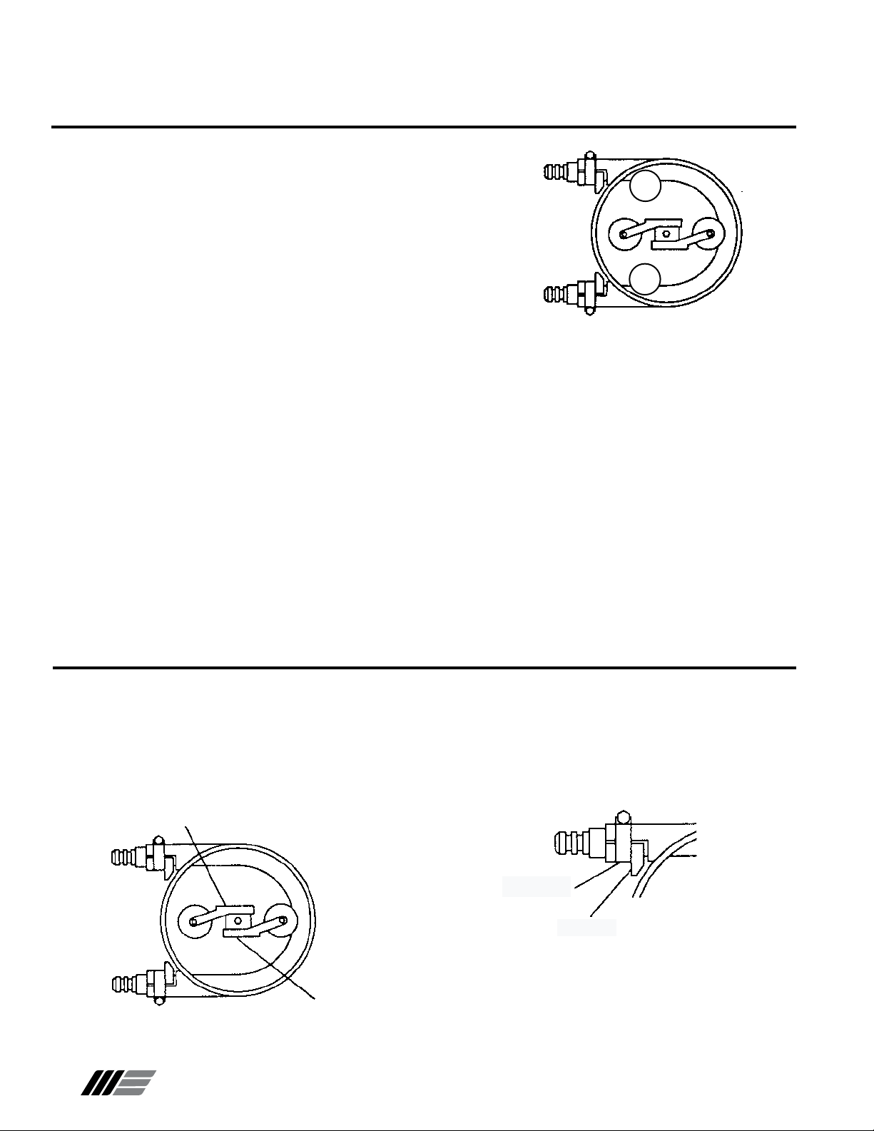
Service (Models 2002, 2003, 2004, 2005)
Replacing Worn Hose
Remove Old Hose
1. Turn off and lock out all power to pump motor.
2. Remove front cover from pump (four screws).
3. See Figure 4. Position pressure rollers as shown.
4
Figure 4
Wanner Engineering, Inc.
4. Loosen screw(s) that secure mounting bracket of pressure
roller which is compressing hose. To maintain correct hose
compression adjustment, DO NOT loosen opposite roller’s
mounting bracket.
5. See Figure 5. Loosen hose clamp bolts. Remove hose
supports and clamps that secure both ends of hose.
6. Remove hose from pump casing.
Figure 5
7. Pull (cut hose if needed) hose connectors from worn hose.
Clean if reusable.
8. Carefully clean pump casing and front cover.
United States Instant Information: www.vectorpump.com
(612) 332-5681 Fax (612) 332-6937 VEC-991-2400A
Page 5

Service (Models 2002, 2003, 2004, 2005)
W0460
Roller adjustment
position
W0461
Inlet (Suction)
Opening
W0462
Measure
here.
Measure
here.
These two dimensions
should be the same.
Install New Hose
1. Check for correct length of hose:
Model 2002: 13 in. (330 mm)
Model 2003: 15 3/8 in. (390 mm)
Model 2004: 23 1/4 in. (590 mm)
Model 2005: 33 7/8 in. (860 mm)
2. Install connectors in new hose.
3. Make sure that pressure rollers are in same position as before.
See Remove Old Hose, Step 3.
4. Position bent hose inside pump casing.
5. Push upper connector against end of pump casing. Install
top hose clamp and secure its bolt.
6. Repeat Step 5 on lower connection.
Important: On models 2002 through 2005, make sure the
hose lays completely against the inside of the pump casing.
7. Smear non-petroleum silicone grease on inner surface of
hose (where rollers contact hose).
8. S e t roller pres s ure accor ding to proced ure follo wing
(steps 2 thru 6).
a. If there is vacuum on first attempt, rollers are set.
b. See Figure 8. If not enough vacuum, gradually move rollers
forward in 1/32 to 1/8 in. (0.8 to 3.0 mm) increments and
repeat test until suction seems to be correct. (Make sure
compression is same for both rollers by measuring roller
bracket in relation to rectangular rotor block).
Figure 7
Setting Roller Pressure
Note: This pressure setting must be checked when a new hose
is installed, because of variations in hose thickness.
1. Remove front cover from pump.
2. See Figure 6. Loosen all roller bracket screws and slide both
rollers away from the hose to reduce compression on the
hose. Retighten all roller bracket screws.
3. See Figure 7. Start pump. Place palm of hand over suction
opening and check for vacuum.
Figure 6
Figure 8
4. Test pump in full operation, and readjust as necessary.
5. Reattach front cover.
Wanner Engineering, Inc.
United States Instant Information: www.vectorpump.com
(612) 332-5681 Fax (612) 332-6937 VEC-991-2400A
5
Page 6

Service (Models 2006, 2007)
W0465
Point
A
W0463
Roller
Holder
Rotor
W0464
Hose Support
Hose Clamp
W0459
W0466
Inlet (Suction)
Opening
Replacing a Worn Hose
Remove Old Hose
1. Turn off and lock out all power to pump motor.
2. Remove front cover from pump (four screws).
3. See Figure 9. Position rotor as shown.
Figure 9
4. Remove roller holder (two screws) not compressing hose.
Also remove any shims under it.
5. See Figure 10. Turn rotor 180° as shown.
Figure 10
5. See Figure 11. Loosen clamp bolts. Remove hose supports
and clamps that secure both ends of hose.
Install New Hose
1. Check for correct length of hose:
Model 2006: 45 1/4 in. (1150 mm)
Model 2007: 57 1/4 in. (1455 mm)
2. Install connectors in new hose.
3. Position bent hose inside pump casing.
4. Push upper connector against end of pump casing. Install
top clamp and secure clamp bolt.
5. Repeat Step 4 on the lower connection.
Important: On models 2006
and 2007, allow a 1-1.5 mm gap
between the hose and the inside
of the pump casing at Point A as
shown in the illustration at right.
6. Smear non-petroleum silicone grease on inner surface of
hose (where rollers contact hose).
7. Turn the rotor 180°. Reinstall the roller holder without shims.
8. Set roll er press ure accord ing to proc e dure followin g
(steps 3 thru 7).
Setting Roller Pressure
Note: The pressure setting must be checked when a new hose
is installed, because of variations in hose thickness.
1. Remove front cover from pump (four screws).
2. Remove any shims under two roller holders.
3. Be sure bolts securing roller holders are tight.
4. See Figure 12. Start pump. Place palm of hand over suction
opening and check for vacuum.
a. If there is vacuum on first attempt, rollers are set.
b. If not enough vacuum, gradually add 0.5 mm (.02 in.) shims
under one of rollers and repeat test until suction seems to
be correct. Do not install more than four shims under
each roller.
Figure 11
6. Remove hose from pump casing.
7. Pull (cut hose if needed) hose connectors from worn hose.
Clean if reusable.
8. Carefully clean pump casing and front cover.
6
Wanner Engineering, Inc.
Figure 12
5. Add same number of shims under other roller.
6. Test pump in full operation, and readjust as necessary.
7. Reattach front cover.
United States Instant Information: www.vectorpump.com
(612) 332-5681 Fax (612) 332-6937 VEC-991-2400A
Page 7

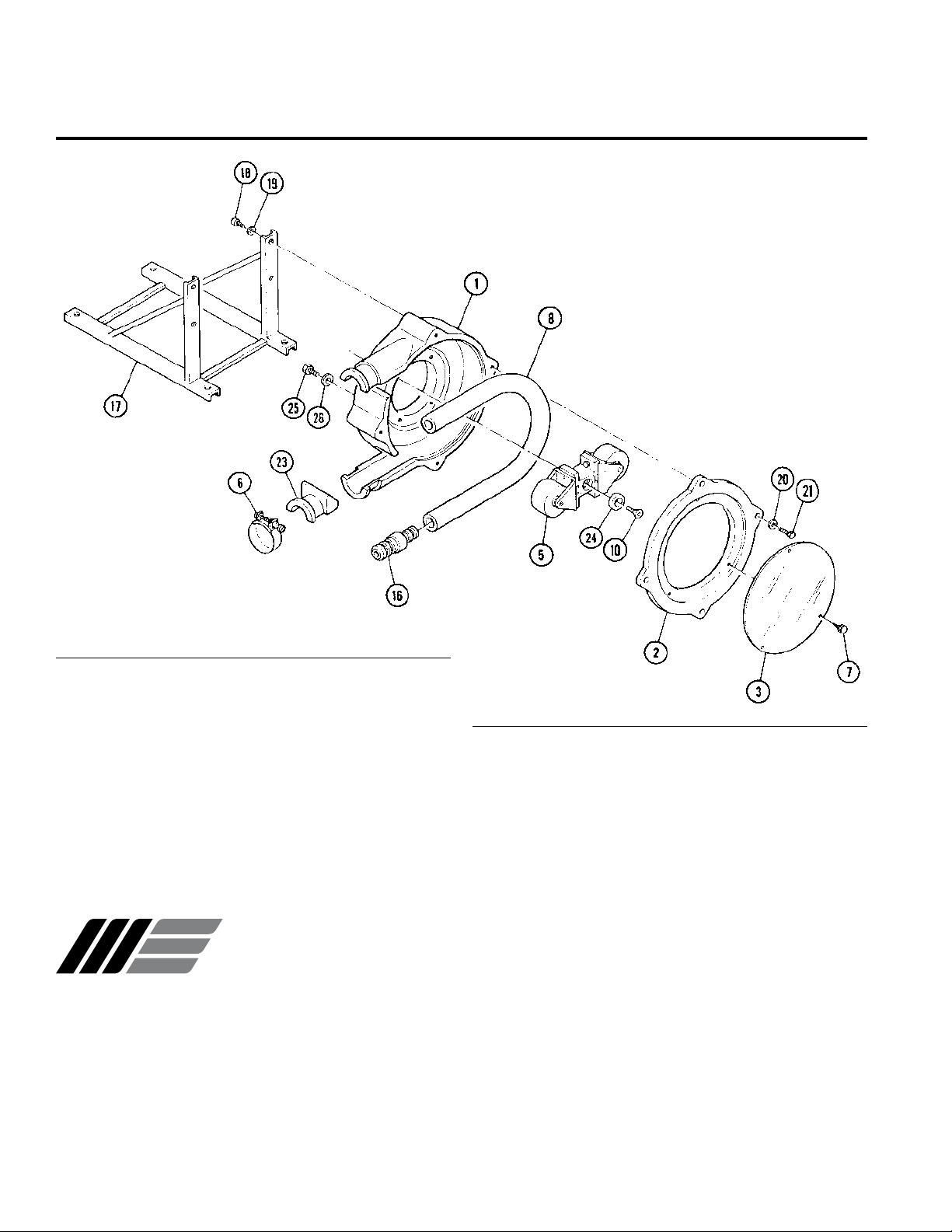
Parts List (Models 2002, 2003, 2004)
W0467
Ref. Qty, per
No. Description Pump
1 Casing
2 Cover, front ........................................................
3 Window, cover ...................................................
4 Bracket, mounting .............................................
5 Roller assembly .................................................
6 Clamp, hose
7 Screw, cover ...............................................
8 Hose ..................................................................
9 Key, motor (non shown) .....................................
10 Screw, roller .......................................................
................................................................ 1
....................................................... 2
1 or 2
Ref. Qty, per
No. Description Pump
11 Stud ...................................................................
1
16 Connector, hose ................................................
1
17 Base ...................................................................
1
18 Bolt, mounting ...................................................
1
19 Nut .....................................................................
20 Washer .............................................................
21 Bolt, cover ..........................................................
1
22 Key, roller assembly (not shown) ......................
2
23 Support, hose ....................................................
1
24 Washer, roller mounting ....................................
4
1
1
6
6
16
4
1
2
1
Wanner Engineering, Inc.
United States Instant Information: www.vectorpump.com
(612) 332-5681 Fax (612) 332-6937 VEC-991-2400A
7
Page 8
W0468
See note.
Parts List (Models 2005, 2006, 2007)
Notes:
• Models 2006 and 2007 use 0.5 mm shims to adjust the hose
compression.
• Model 2005 uses the same style of roller assembly as Models
2002 – 2004 (see previous page.
Ref. Qty, per
No. Description Pump
1 Casing
2 Cover, front ........................................................
3 Window, cover ................................................... 1
5 Roller assembly ................................................. 1
6 Clamp, hose....................................................... 4
7 Screw, cover ............................................... 2 or 3
8 Hose .................................................................. 1
10 Screw, roller ....................................................... 1
................................................................ 1
1
WANNER ENGINEERING, INC.
1204 Chestnut Avenue, Minneapolis, MN 55403
TEL: (612) 332 - 56 81 FAX: (612) 332- 69 37
TOLL-FREE FAX [US only]: (800) 332-6812
Ref. Qty, per
No. Description Pump
16 Connector, hose ................................................
17 Base ...................................................................
18 Bolt, mounting ................................................... 4
19 Washer .............................................................. 4
20 Washer .............................................................. 4
21 Bolt, cover .......................................................... 4
23 Support, hose .................................................... 2
24 Washer, roller mounting .................................... 1
25 Bolt ..................................................................... 4
26 Washer ................................................................
— Shim, 0.5 mm (.02 in.) ............................... 8 max
1
1
www.vectorpump.com
email: sales@wannereng.com
8
© 2004 Wanner Engineering, Inc. Printed in USA
VEC-991-2400A 10/2004, Revised 8/2007
 Loading...