

Vecow UMBC-1100 User Manual

USER
USER
UMBC-1100
Intel® Xeon®/Core™ i7/i5/i3 Processor MicroATX Motherboard
Workstation-grade Intel
®
C246 PCH, 4 GigE LAN, 6 USB 3.1, 5 COM, M.2, 3 PCIe
Manual
Manual
1.0.0 Edition 20191216

Record of Revision
Version Date
0.10 2019/12/11 All Preliminary Release
1.00 2019/12/16 Ocial Release
Page Description
Remark
©Vecow UMBC-1100 User Manual
ii

Disclaimer
This manual is released by Vecow Co., Ltd. for reference purpose only. All
product oerings and specications are subject to change without prior notice.
It does not represent commitment of Vecow Co., Ltd. Vecow shall not be liable
for direct, indirect, special, incidental, or consequential damages arising out of
the use of the product or documentation or any infringements upon the rights of
third parties, which may result from such use.
Declaration of Conformity
FCC
CE
This equipment has been tested and found to comply with the limits for a Class
A digital device, pursuant to part 15 of the FCC Rules. These limits are designed
to provide reasonable protection against harmful interference when the
equipment is operated in a commercial environment. This equipment generates,
uses, and can radiate radio frequency energy, and if it is not installed and used
in accordance with the instruction manual, it may cause harmful interference to
radio communications. Operation of this equipment in a residential area is likely
to cause harmful interference in which case the user will be required to correct
the interference at his own expense.
The products described in this manual complies with all applicable European
Union (CE) directives if it has a CE marking. For computer systems to
remain CE compliant, only CE-compliant parts may be used. Maintaining CE
compliance also requires proper cable and cabling techniques.
Copyright and Trademarks
This document contains proprietary information protected by copyright. No part
of this publication may be reproduced in any form or by any means, electric,
photocopying, recording or otherwise, without prior written authorization
by Vecow Co., Ltd. The rights of all the brand names, product names, and
trademarks belong to their respective owners.
©Vecow UMBC-1100 User Manual
iii
Order Information
Part Number Description
UMBC-1100 MicroATX Motherboard, Intel® C246 with Intel® Xeon®/
UMBC-1100
Core™ i7/i5/i3 Processor (CFL-R S/CFL-S), 4 GigE LAN, 6 USB 3.1,
4 COM, 8 SATA III, 1 M.2, 1 PCIe x16, 2 PCIe x4, 16 GPIO
CPU List
Series CPU Cores GHz TDP (W) CPU
®
Intel
Xeon
®
Intel
Core™
E-2278GE 8 4.7 80
E-2278GEL 8 3.9 35
®
E-2226GE 6 4.6 80
i7-9700E
8
i7-9700TE 3.8 35 i7-8700T 6 4 35
i5-9500E
6
i5-9500TE 3.6 35 i5-8500T 6 3.5 35
i3-9100E
4
i3-9100TE 3.2 35 i3-8100T 4 3.1 35
4.4 65 i7-8700 6 4.6 65
4.2 65 i5-8500 6 4.1 65
3.7 65 i3-8100 4 3.6 65
E-2176G 6 4.6 80
E-2124G 4 4.5 71
Cores
GHz TDP (W)
©Vecow UMBC-1100 User Manual
iv

Optional Accessories
Part Number Description
DDR4 32G Certied DDR4 32GB 2666MHz U-DIMM
DDR4 16G Certied DDR4 16GB 2666MHz U-DIMM
DDR4 8G Certied DDR4 8GB 2666MHz U-DIMM
DDR4 4G Certied DDR4 4GB 2666MHz U-DIMM
COM Port Cable COM Cable with DB9 Connector
SATA Data Cable SATA Cable with 7P SATA Vertical SATA Connector
USB 3.1 Cable USB Cable with Dual USB 3.1 Type A Connector
USB 2.0 Cable USB Cable with Dual USB 2.0 Type A Connector
1U CPU Cooler CPU Cooler for 1U Chassis
2U CPU Cooler CPU Cooler for 2U Chassis
©Vecow UMBC-1100 User Manual
v

Table of Contents
CHAPTER 1 GENERAL INTRODUCTION 1
1.1 Overview 1
1.2 Features 2
1.3 Product Specication 3
1.4 Supported CPU List 5
1.5 Mechanical Dimension 6
CHAPTER 2 GETTING TO KNOW YOUR UMBC-1100 7
2.1 Packing List 7
2.2 Front Panel I/O Functions 8
2.2 Connector/Jumper Locations 11
2.3 Jumper Settings 28
CHAPTER 3 SYSTEM SETUP 31
3.1 Installing CPU 31
3.2 Installing CPU Cooler 32
3.3 Installing ATX Power 33
3.4 Installing DDR4 U-DIMM Modules 34
3.5 Installing M.2 35
CHAPTER 4 BIOS SETUP 36
4.1 Entering BIOS Setup 36
4.2 Main 37
4.3 Advanced 37
4.4 Chipset 48
4.5 Security 54
4.6 Boot 56
4.7 Save & Exit 57
©Vecow UMBC-1100 User Manual
vi

APPENDIX A : Isolated DIO Guide 58
APPENDIX B : Software Functions 61
APPENDIX C : RAID Functions 63
APPENDIX D : Power Consumption 67
APPENDIX E : Supported Memory & Storage List 69
©Vecow UMBC-1100 User Manual
vii

1
GENERAL INTRODUCTION
1.1 Overview
Vecow UMBC-1100 is a high performance industrial MicroATX Motherboard.
Workstation-grade Intel® C246 chipset exible supports 8-core 9th Generation
Intel® Xeon®/Core™ i7/i5/i3 processor (CFL-R S/CFL-S), 4 DDR4 U-DIMM
sockets support 2666MHz up to 128GB ECC memory, advanced Intel® UHD
Graphics 630 supporting DirectX 12 and OpenGL 4.5 API, and up to Ultra HD
4K resolution, Vecow UMBC-1100 MicroATX Motherboard delivers leading
system productivity; Multiple PCIe 3.0 (8GT/s), SATA III (6Gbps), USB 3.1
(5Gbps), and GigE LAN (1Gbps) connections make high-speed data transfer
possible.
Fanless design supporting 0°C to 60°C operating temperature, onboard
DisplayPort, VGA and HDMI display interfaces support triple independent
displays and up to 4K resolution; 4 GigE LAN, 5 COM RS-232/422/485, 8
SATA III, 6 USB 3.1, 4 USB 2.0, 16 GPIO; 1 PCIe x16, 2 PCIe x4, and 1 M.2
expansion; iAMT 12.0, TPM 2.0, Wake on LAN and PXE smart manageability,
Vecow ECX-1000 Series 5,25" SBC serves compact & exible solutions to meet
your project requirements.
Workstation-grade Intel
with Intel® C246 chipset, leading performance and system productivity, flexible
expansion, industrial-grade reliability and integrated features, Vecow UMBC-1100
MicroATX Motherboard is your powerful solution for Smart Manufacturing,
Public Surveillance, Gaming, Self-service System, Traffic Control and any
performance-driven Industrial 4.0/AIoT applications.
©Vecow UMBC-1100 User Manual
®
Xeon®/Core™ i7/i5/i3 processor (Coffee Lake), running
GENERAL INTRODUCTION
1

1.2 Features
• Workstation-grade Platform : LGA 1151 Socket supports 8 cores 9th Generation
®
Intel
Xeon®/Core™ i7/i5/i3 Processor (Coffee Lake-Refresh s) running with
®
Intel
C246 Chipset
• Supports DDR4 2666/2400MHz U-DIMM memory, up to 128GB (ECC/Non-ECC)
• Display : VGA, DisplayPort and HDMI display interfaces, up to 4K resolution
• 4 Independent GigE LAN, iAMT 12.0 supported
• Storage : 8 SATA III support RAID 0, 1, 5, 10 data protection
• 6 USB 3.1, 4 USB 2.0
• 5 COM RS-232/422/485, 16 GPIO
• Expansion : 1 PCIe x16, 2 PCIe x4, 1 M.2
• Supports case open detection
• Optional supports TPM 2.0/1.2
©Vecow UMBC-1100 User Manual
GENERAL INTRODUCTION
2

1.3 Product Specication
System
Processor
Chipset Intel® C246 Chipset
BIOS AMI
SIO IT8786E
Memory
8 cores Intel® Xeon®/Core™ i7/i5/i3 Processor
(CFL-R S/CFL-S)
• DDR4 2666MHz (ECC/Non-ECC)
• Up to 128GB
• 4 288-pin U-DIMM Socket
Graphics
Graphics Processor Intel® UHD Graphics 630
3 display interfaces :
Interface
• 1 VGA : Up to 1920 x 1200 @60Hz
• 1 DisplayPort : Up to 4096 x 2160 @60Hz
• 1 HDMI : Up to 4096 x 2160 @24Hz
Ethernet
LAN 1 Intel® I219LM GigE LAN supports iAMT 12.0
LAN 2 Intel
LAN 3 Intel
®
I211 GigE LAN
®
I211 GigE LAN
LAN 4 Intel® I211 GigE LAN
Audio
Audio Codec Realtek ALC892, 5.1 Channel HD Audio
Audio Interface 1 Mic-in, 1 Line-out
Storage
SATA 8 SATA III (6Gbps) support S/W RAID 0, 1, 5, 10
I/O Interface
• 1 HDMI Connector
• 1 DisplayPort Connector
Rear I/O
Internal I/O
• 1 VGA Connector
• 4 RJ45 Connector
• 4 USB 3.1 Tape A Connector
• 5 COM RS-232/422/485 Header
• 8 SATA Connector
• 4 USB 2.0 Header
• 2 USB 3.1 Header
• 1 GPIO Header
• 1 CPU Fan Header
• 4 System Fan Header
©Vecow UMBC-1100 User Manual
GENERAL INTRODUCTION
3

Expansion
PCIe x16 1 PCIe x16 Slot (Gen 3)
PCIe x4 2 PCIe x4 Slot (Gen 3)
M.2 1 M.2 Key M Socket
Power
Input Voltage
Power Type ATX Input
Power Interface
+12V +5V +3.3V 5VSB
7.25A 0.58A 0.27A 0.07A
• 1 24-pin ATX Power Connector
• 1 8-pin 12V ATX Power Connector
Others
TPM Optional Inneon SLB9665 supports TPM 2.0, LPC interface
Watchdog Timer Reset : 1 to 255 sec./min. per step
Smart Management Wake on LAN, PXE supported
HW Monitor
Monitoring temperature, voltages. Auto throttling control when
CPU overheats.
Software Support
OS Windows 10, Linux
Mechanical
Dimension (W x L) 244.0mm x 244.0mm (9.60" x 9.60")
Weight 1450 g (3.2 lb)
Environment
Operating Temperature 0°C to 60°C (-32°F to 140°F)
Storage Temperature -40°C to 85°C (-40°F to 185°F)
Humidity 5% to 95% humidity, non-condensing
Relative Humidity 95% at 60°C
EMC CE, FCC
©Vecow UMBC-1100 User Manual
GENERAL INTRODUCTION
4

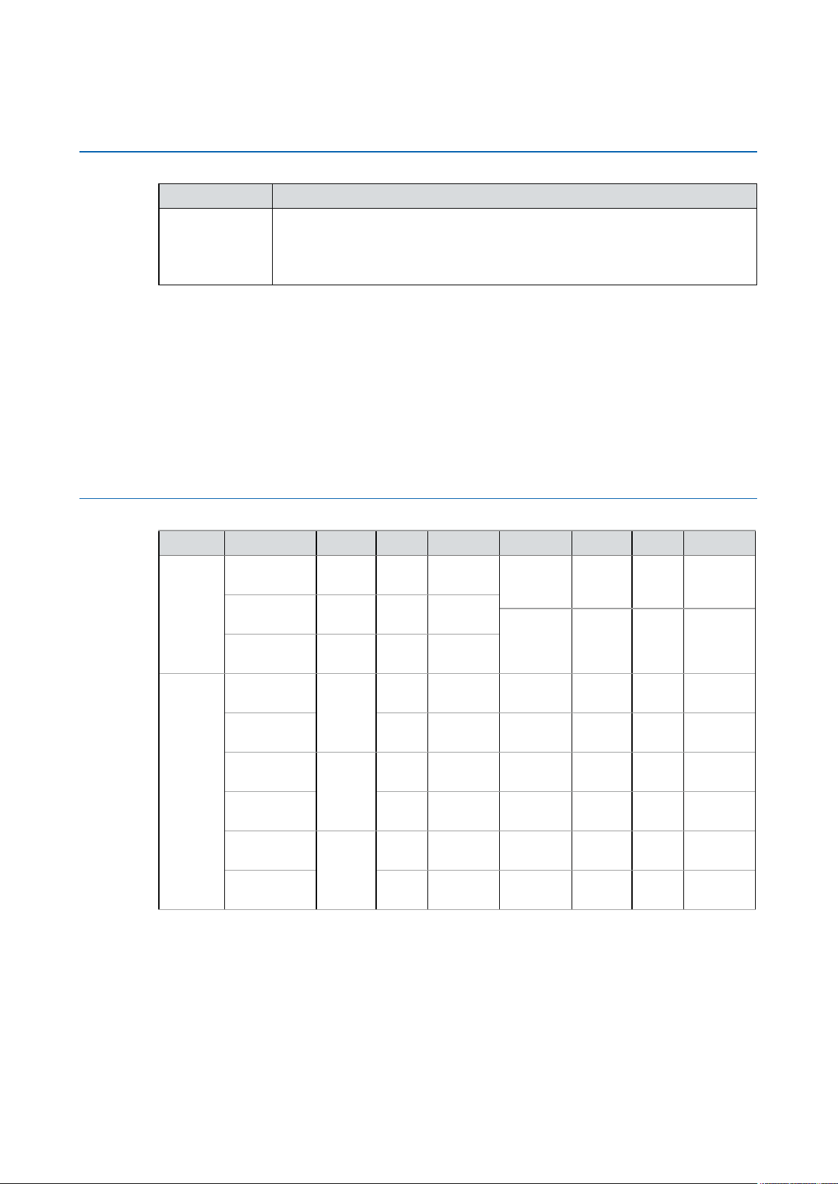
1.4 Supported CPU List
Processor No. Cores TDP Cache Max. Frequency ECC Memory
®
Intel
Xeon® E-2278GE 8 80W 16M Up to 4.7GHz Y
®
Intel
Xeon® E-2278GEL 8 35W 16M Up to 3.9GHz Y
®
Intel
Xeon® E-2226GE 6 80W 12M Up to 4.6GHz Y
®
Intel
Xeon® E-2176G 6 80W 12M Up to 4.6GHz Y
®
Intel
Xeon® E-2124G 4 71W 8M Up to 4.6GHz Y
®
Intel
Core™ i7-9700E 8 65W 12M Up to 4.4GHz N
®
Intel
Core™ i7-9700TE 8 35W 12M Up to 3.8GHz N
®
Intel
Core™ i7-8700 6 65W 12M Up to 4.6GHz N
®
Intel
Core™ i7-8700T 6 35W 12M Up to 4.0GHz N
®
Intel
Core™ i5-9500E 6 65W 9M Up to 4.2GHz N
®
Intel
Core™ i5-9500TE 6 35W 9M Up to 3.6GHz N
®
Intel
Core™ i5-8500 6 65W 9M Up to 4.1GHz N
®
Intel
Core™ i5-8500T 6 35W 9M Up to 3.5GHz N
®
Intel
Core™ i3-9100E 4 65W 6M Up to 3.7GHz Y
®
Intel
Core™ i3-9100TE 4 35W 6M Up to 3.2GHz Y
®
Intel
Core™ i3-8100 4 65W 6M Up to 3.6GHz Y
®
Intel
Core™ i3-8100T 4 35W 6M Up to 3.1GHz Y
©Vecow UMBC-1100 User Manual
GENERAL INTRODUCTION
5
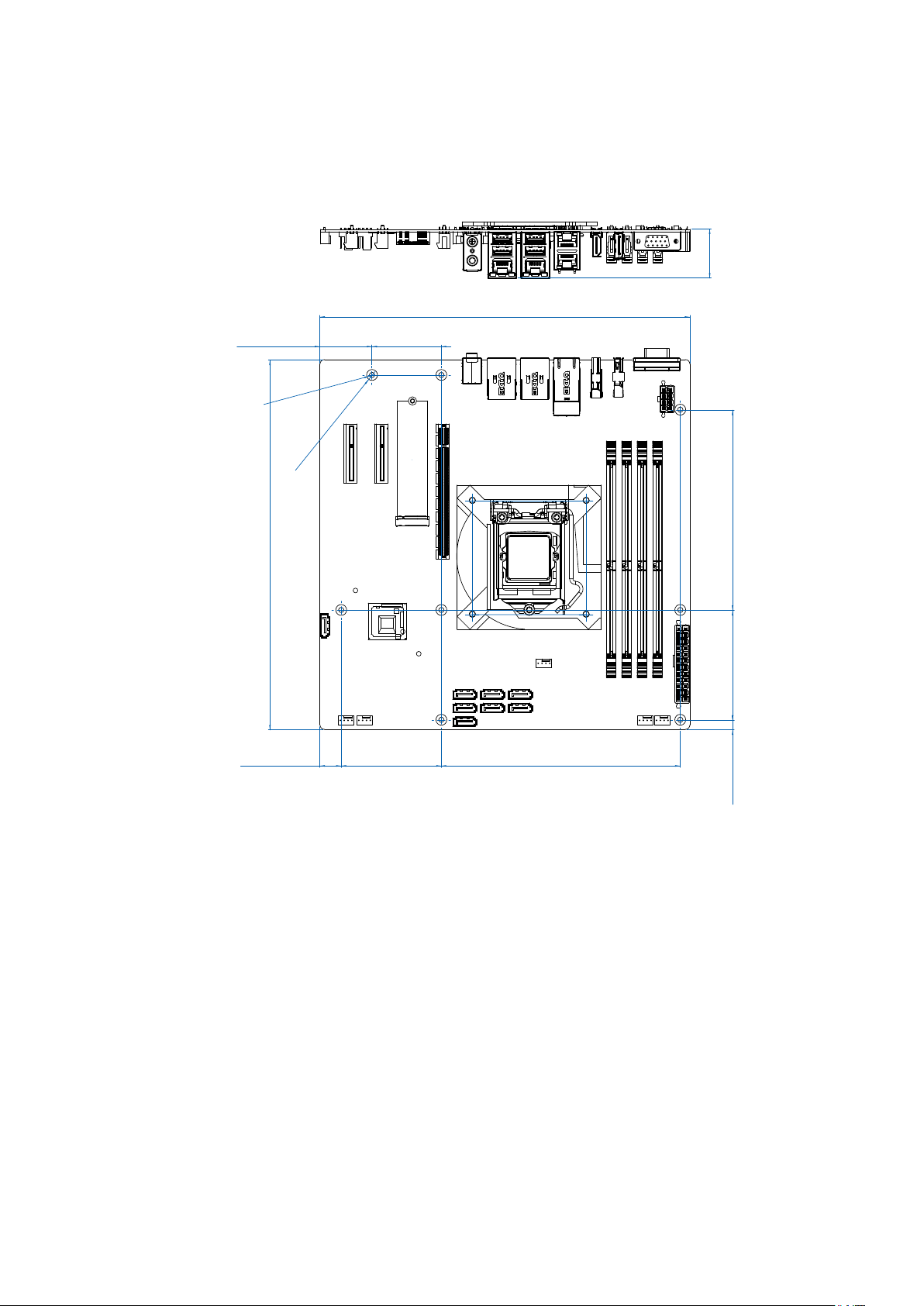
1.5 Mechanical Dimension
32.4 (1.27")
Unit : mm (inch)
243.8 (9.60)
34.3 (1.35)
Ø3.5 (0.14)
Ø7.2 (0.28)
243.8 (9.60)
14.0 (0.55)
45.7 (1.80)
66.0 (2.60)
132.1 (5.20)
72.4 (2.85)
157.5 (6.20)
6.4 (0.25)
©Vecow UMBC-1100 User Manual
GENERAL INTRODUCTION
6
2
GETTING TO KNOW YOUR UMBC-1100
2.1 Packing List
Item Description Qty
1 UMBC-1100 MicroATX Motherboard 1
2 Driver/User Manual DVD 1
3 IO Shield 1
©Vecow UMBC-1100 User Manual
GETTING TO KNOW YOUR UMBC-1100
7
2.2 Front Panel I/O Functions
In Vecow's UMBC-1100 series family, all I/O connectors are located on the front
panel. Most of the general connections to the computer device, such as audio,
USB, RJ45,HDMI,Display Port, and any VGA, are placed on the front panel.
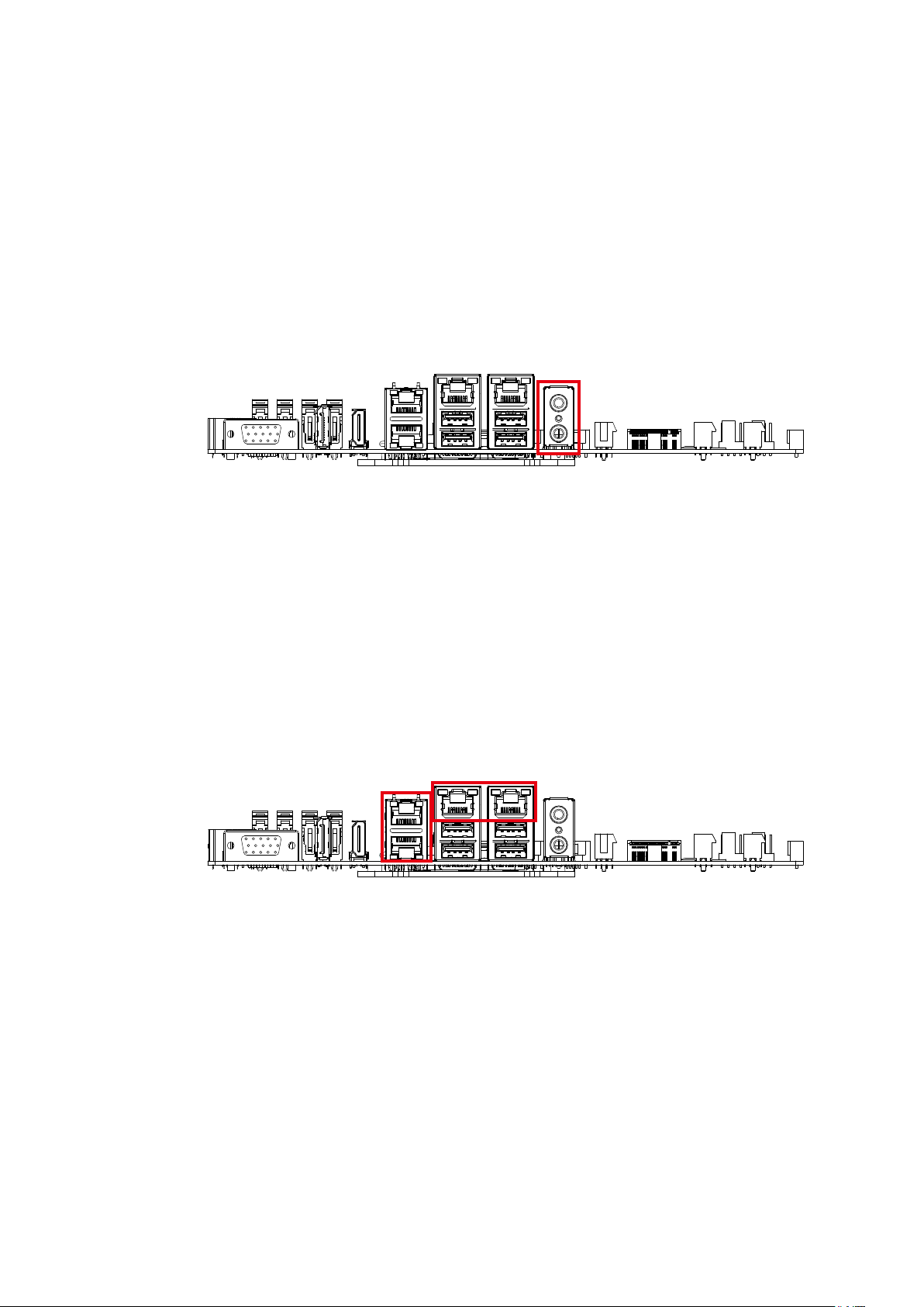
2.2.1 Audio Connector
There are two audio connectors, mic-in and line-out, on the front side of UMBC-1100.
Onboard Realtek ALC892 audio codec supports 5.1 channel HD audio and fully
complies with Intel
®
High Denition Audio (Azalia) specications.
To utilize the audio function on the Windows platform, you need to install
®
corresponding drivers for both Intel
C246 chipset and Realtek ALC892 codec.
Please refer to chapter four for more details on driver installation.
2.2.2 10/100/1000 Mbps Ethernet Port
There are two 8-pin RJ-45 jacks supporting 10/100/1000 Mbps Ethernet
connections in the front side of UMBC-1100. LAN1 is powered by Intel® I219-LM
Ethernet engine; LAN2,LAN3 and LAN4 are powered by Intel® I211-AT Ethernet
engine. When both LAN1, LAN2,LAN3 and LAN4 work in normal status, basic
iAMT function is enabled.
Using suitable RJ-45 cable, you can connect UMBC-1100 system to a computer
or to any other devices with Ethernet connection, for example, a hub or a switch.
Moreover, LAN1,LAN2,LAN3 and LAN4 supports Wake on LAN and Pre-boot
functions. The pinouts of LAN1,LAN2,LAN3 and LAN4 are listed as follow :
©Vecow UMBC-1100 User Manual
GETTING TO KNOW YOUR UMBC-1100
8
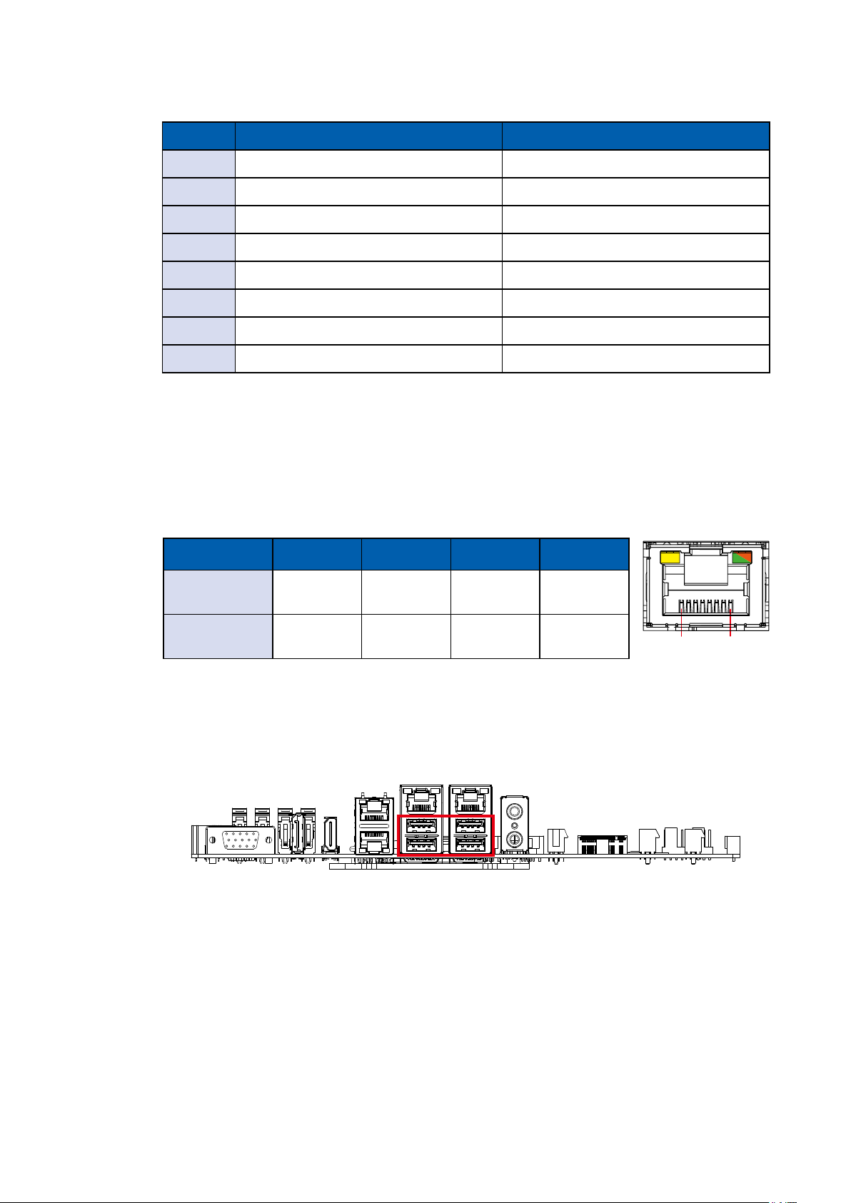
Pin No. 10/100 Mbps 1000Mbps
1 E_TX+ MDI0_P
2 E_TX- MDI0_N
3 E_RX+ MDI1_P
4 ------ MDI2_P
5 ------ MDI2_N
6 E_RX- MDI1_N
7 ------ MDI3_P
8 ------ MDI3_N
Each LAN port is supported by standard RJ-45 connector with LED indicators to
present Active/Link/Speed status of the connection.
The LED indicator on the right bottom corner lightens solid green when the cable
is properly connected to a 100Mbps Ethernet network and solid orange when the
cable is properly connected to a 1000Mbps Ethernet network. The left LED will
keep blinking o when Ethernet data packets are being transmitted/received.
LED Location LED Color 10Mbps 100Mbps 1000Mbps
Right
Left Yellow
Green/
Orange
O
Blinking
Yellow
Solid
Green
Blinking
Yellow
Solid
Orange
Blinking
Yellow
8 1
2.2.3 USB 3.1
There are 4 USB 3.1 Gen1 connections available supporting up to 5GB per
second data rate in the top side of UMBC-1100. They are also compliant with
the requirements of SuperSpeed (SS), high speed (HS), full speed (FS) and low
speed (LS).
©Vecow UMBC-1100 User Manual
GETTING TO KNOW YOUR UMBC-1100
9
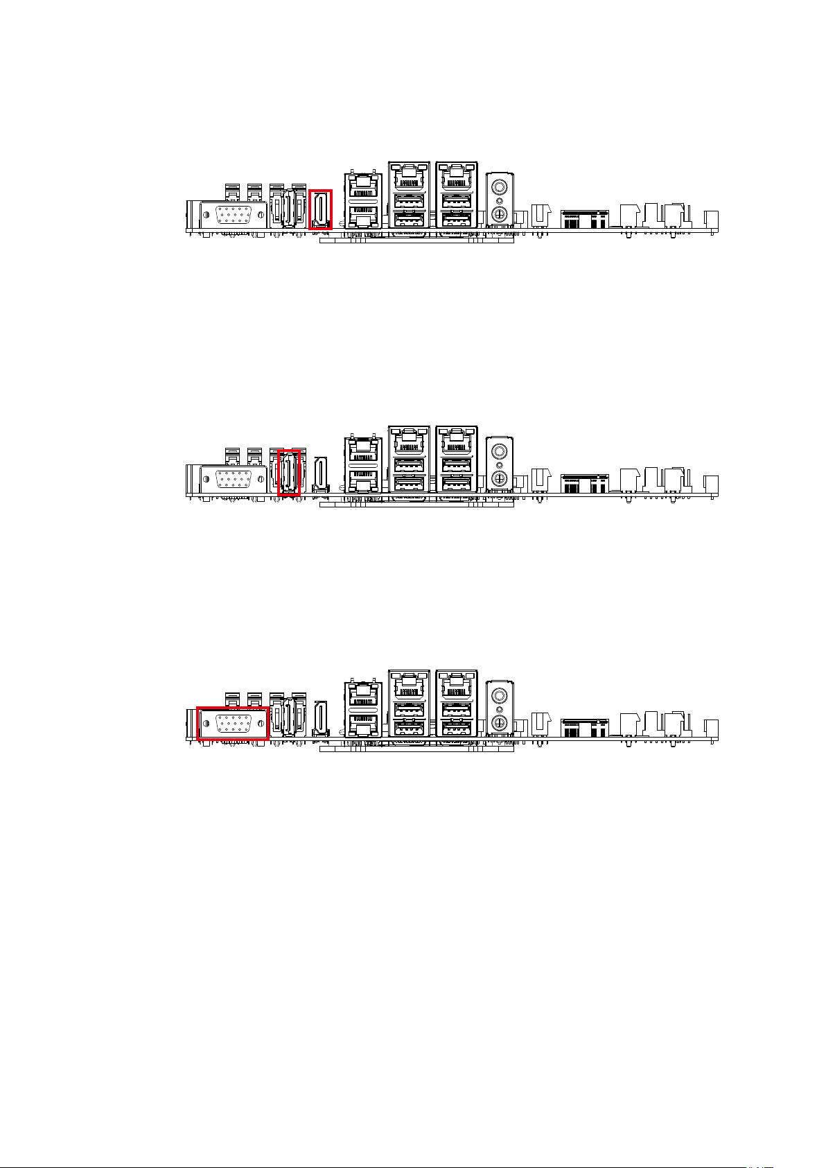
2.2.4 HDMI
Onboard HDMI Port supports DDC channel mode. The connection supports up
to 4096x2160 @24Hz.
2.2.5 DISPLAY PORT
UMBC-1100 supports single Display Port and up to 4096 x 2304 pixels resolution.
2.2.6 VGA
UMBC-1100 supports single VGA and up to 1920 x 1200 pixels resolution.
©Vecow UMBC-1100 User Manual
GETTING TO KNOW YOUR UMBC-1100
10
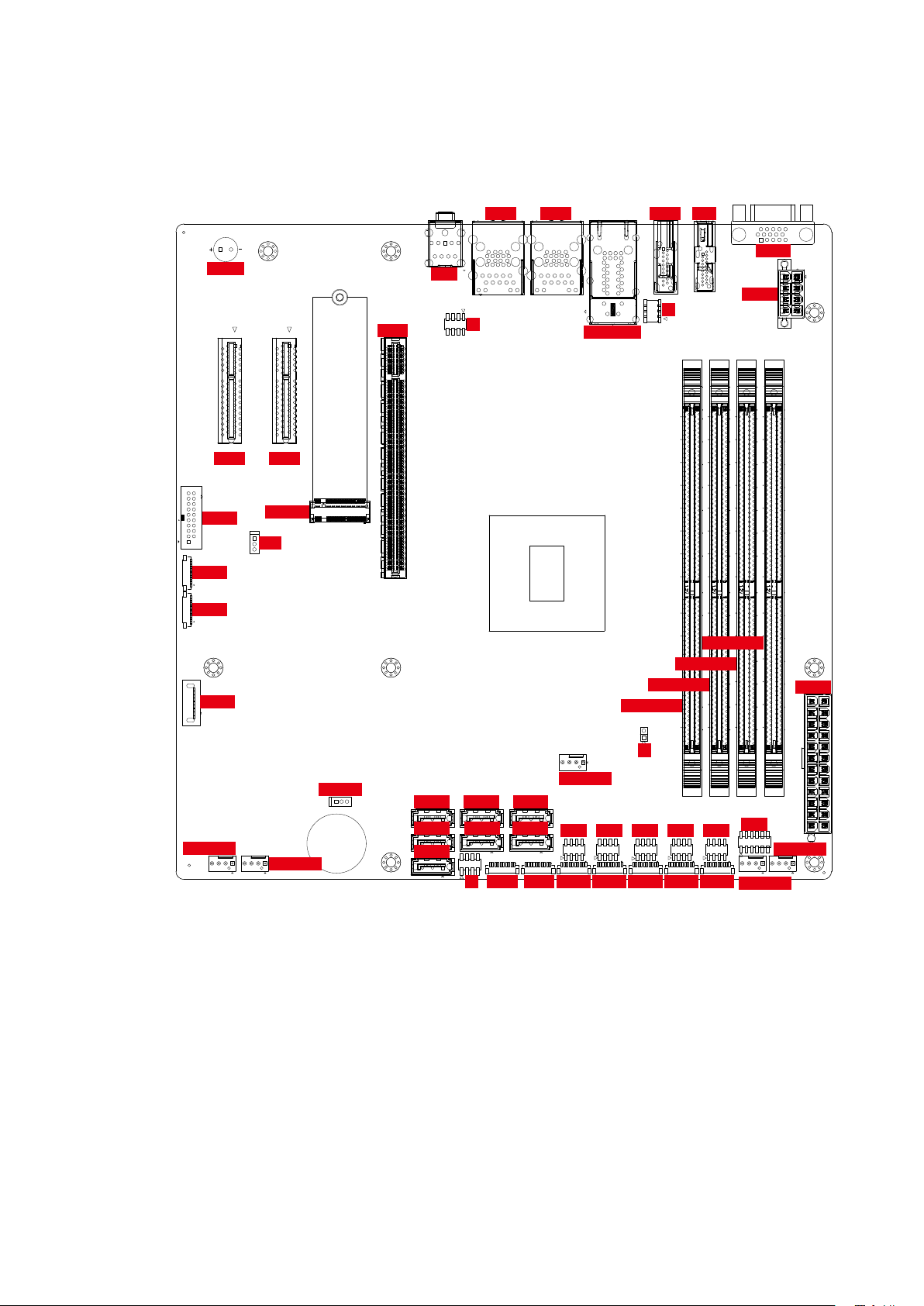
2.2 Connector/Jumper Locations
1
2.2.1 Top Side
CN15CN14
Buzzer
A2B2A1
B1
A32
A31
B31
B32
CN20 CN22
11
12 345
U4 U1
U5
U13
22 25
CN6
A2B2A1
B1
A32
A31
B31
B32
CN19
B2
B1
A1
A2
U14
1
R1
4
R2
L1
L2
1
7
J5
2
8
U4
U9
U10
U18
R9
R10
L4L3
U1
U5
U9
U13
U10
U18
U14
R1
R9
R2
R10
L2L1
L3
L5
L1
R1
L4
R10
R11
CN_LAN34
CN4CN23
11 15
10
6
5
146
1
1
VGA2
JPWR2
146
1
4
1
146
L8
L4
R13
R22
7
8
R23
R12
R24
J4
2
1
1
146
JUSB3
11019
10
JUSB2
10
JUSB1
1
SATA8
SYS_FAN1
M2_CN1
JP6
B81
A81
A82
B82
220
77
222
79
220
220
77
77
220
77
79
222
222
222
79
79
P1_DIMMA4
P1_DIMMA3
P1_DIMMA2
JPWR1
P1_DIMMA1
143
143
1
4
7 1
7 1
10
1
CPU_FAN1
SW1 SW2 SW3 SW4 SW5
8
2
1
7
1
1
10
JCOMS1
SYS_FAN2
14
14
SATA7 SATA4 SATA3
2
1
7
SATA6 SATA2 SATA1
1
7
SATA5
7 1
1
7
7
1
8
2
10
71
JDIO2J1 JDIO1 JCOM1 JCOM2 JCOM3 JCOM4 JCOM5
J2
8
2
1
8
2
1
7
7
1
110 1
10
2
1
10
143
143
288
288
30
20
2
8
8
1
1
7
7
1
10
288
CN3
2
14 14
SYS_FAN3
288
12
SYS_FAN4
11
24
12
©Vecow UMBC-1100 User Manual
GETTING TO KNOW YOUR UMBC-1100
11
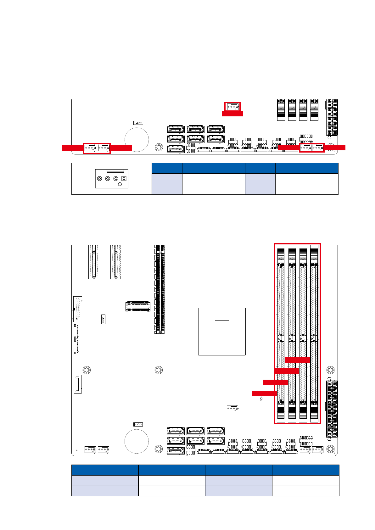
2.2.2 CPU and SYS FAN Connector
4
1
1
5
6
10
11 15
11019
11
1
A2B2A1
B1
A32
A31
B31
B32
A2B2A1
B1
A32
A31
B31
B32
143
222
79
220
77
146
1
143
222
79
220
77
146
1
222
79
220
77
146
222
79
220
77
146
1
1
4
8
7
1
2
8
7
1
2
10
1
10
12 345
22 25
U18
U14
U13
U10
U9
U5
U4
U1
R10
R9
R2
R1
L4
L3
L2L1
U18
U14
U13
U10
U9
U5
U4 U1
R10
R9
R2
R1
L4L3
L2
L1
R24
R12
R23
R11
R22
R10
R13
R1
L8
L5
L4
L1
B81
B82
A81
A82
B2
A2
A1
B1
4
1
1
5
6
10
11 15
1
A2B2A1
B1
A2B2A1
B1
1
4
8
7
1
2
8
7
1
2
12 345
22 25
U18
U14
U13
U10
U9
U5
U4
U1
R10
R9
R2
R1
L4
L3
L2L1
U18
U14
U13
U10
U9
U5
U4 U1
R10
R9
R2
R1
L4L3
L2
L1
R24
R12
R23
R11
R22
R10
R13
R1
L8
L5
L4
L1
B2
A2
A1
B1
The fan power connector is for additional thermal requirements. The pin assignments
of SYS_FAN1, SYS_FAN2, SYS_FAN3, SYS_FAN4 and CPU_FAN1 are listed in
the following table.
143
SYS_FAN1 SYS_FAN2
14
14
143
288
1
4
288
CPU_FAN1
2
7 1
7
7
7 1
1
1
1
7
7
2
7 1
1
8
10
10
1
71
8
2
1
1
10
8
2
2
1
7
1
7
1
110 1
10
2
8
1
7
1
10
30
20
2
8
8
1
7
7
1
10
SYS_FAN3 SYS_FAN4
Pin No. Denition Pin No. Denition
14
1 GND 2 +12V (1.5A max)
3 Fan speed sensor 4 Fan PWM
288
288
12
2
1
11
14 14
2.2.3 P1_DIMMA1, P1_DIMMA2, P1_DIMMA3, P1_DIMM_A4 : DDR4 Slot
There are 4 DDR4 channel onboard, support DDR4 2666/2400/2133, max 64GB
Each channel 16GB.
24
12
1
1
A32
A31
B31
B32
11
11019
10
10
1
A32
A31
B31
B32
B81
B82
A81
A82
146
220
77
77
222
79
79
1
146
146
220
222
146
220
77
220
77
79
222
222
79
P1_DIMMA4
P1_DIMMA3
P1_DIMMA2
2
1
7
1
7
7 1
14
14
1
7
7
1
8
2
10
71
7 1
7 1
10
1
4
2
1
1
10
P1_DIMMA1
1
8
8
2
2
1
7
1
7
1
110 1
10
143
143
2
8
1
7
1
10
143
143
288
288
30
20
2
8
8
1
1
7
7
1
10
288
288
24
12
2
11
14 14
12
Pin No. Denition Pin No. Denition
P1_DIMM_A1 DDR4 Channel A P1_DIMM_A2 DDR4 Channel A
P1_DIMM_A3 DDR4 Channel B P1_DIMM_A4 DDR4 Channel B
©Vecow UMBC-1100 User Manual
GETTING TO KNOW YOUR UMBC-1100
12
4
1
1
5
6
10
11 15
11019
11
1
A2B2A1
B1
A32
A31
B31
B32
A2B2A1
B1
A32
A31
B31
B32
143
288
222
79
220
77
146
1
143
288
222
79
220
77
146
1
143
288
222
79
220
77
146
143
288
222
79
220
77
146
1
1
4
1
4
8
7
1
2
8
7
1
2
10
1
10
12 345
22 25
U18
U14
U13
U10
U9
U5
U4
U1
R10
R9
R2
R1
L4
L3
L2L1
U18
U14
U13
U10
U9
U5
U4 U1
R10
R9
R2
R1
L4L3
L2
L1
R24
R12
R23
R11
R22
R10
R13
R1
L8
L5
L4
L1
B81
B82
A81
A82
B2
A2
A1
B1
2.2.4 J1 : Miscellaneous Pin Header
4
1
1
5
6
10
11 15
11019
11
1
A2B2A1
B1
A32
A31
B31
B32
A2B2A1
B1
A32
A31
B31
B32
222
79
220
77
146
1
222
79
220
77
146
1
222
79
220
77
146
222
79
220
77
146
1
1
4
8
7
1
2
8
7
1
2
10
1
10
12 345
22 25
U18
U14
U13
U10
U9
U5
U4
U1
R10
R9
R2
R1
L4
L3
L2L1
U18
U14
U13
U10
U9
U5
U4 U1
R10
R9
R2
R1
L4L3
L2
L1
R24
R12
R23
R11
R22
R10
R13
R1
L8
L5
L4
L1
B81
B82
A81
A82
B2
A2
A1
B1
2.0mm 2x4p header
This pin header can be used as a backup for following functions, hard drive
LED indicator, reset button, power LED indicator, and power-on/o button,which
already can be accessed by front panel and top panel. The pin-outs of
Miscellaneous port are listed in following table :
2
7 1
1
7
1
7
7 1
14
14
Group Pin No. Description
HDD LED
2
8
Reset button
1
7
Power and standby LED
Power on button
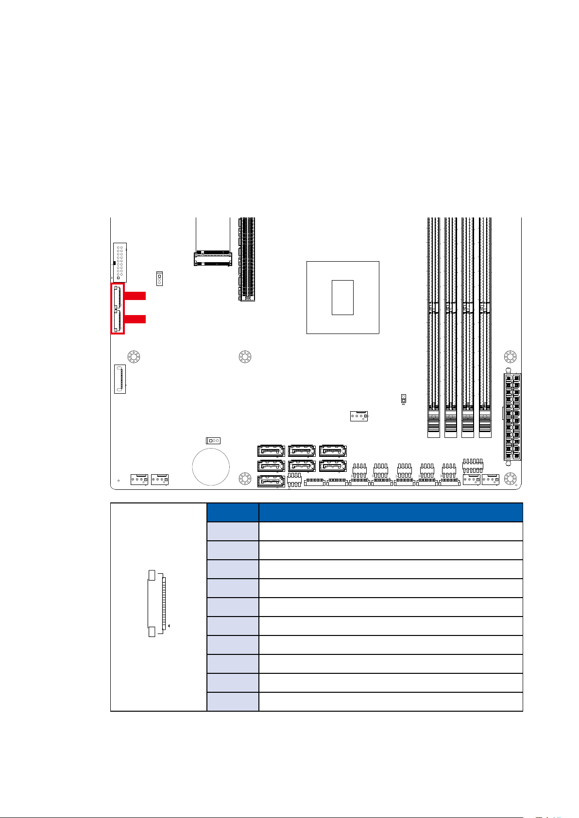
2.2.5 SATA 1 ~ SATA8 : SATA III Connector
Standard 7 PIN SATA Connector
There are 8 onboard high performance Serial ATA III. It supports higher storage
capacity with less cabling eort and smaller required space. The pin assignments
of SATA 1 to 8 are listed in the following table :
1
7
7
2
7 1
1
8
10
10
1
J1
71
8
2
1
1
10
8
2
2
1
7
1
7
1
110 1
10
2
8
1
7
1
10
2
30
20
2
8
8
1
1
7
7
1
10
24
12
11
14 14
12
1 HDD_LED_P
3 HDD_LED_N
5 FP_RST_BTN_N
7 Ground
2 PWR_LED_P
4 PWR_LED_N
6 FP_PWR_BTN_N
8 Ground
SATA8
143
1
4
SATA7
7
SATA6
7
7 1
14
14
SATA5
SATA4
2
1
7
7
1
2
SATA2
7 1
1
7 1
1
8
10
10
1
71
SATA3
8
2
SATA1
1
1
10
8
2
2
1
7
1
7
1
110 1
10
Pin No. Denition Pin No. Denition
17
1 GND 2 TXP
3 TXN 4 GND
5 RXN 6 RXP
143
2
8
1
7
1
10
143
143
288
288
30
20
2
8
8
1
1
7
7
1
10
288
288
24
12
2
11
14 14
12
7 GND
©Vecow UMBC-1100 User Manual
GETTING TO KNOW YOUR UMBC-1100
13
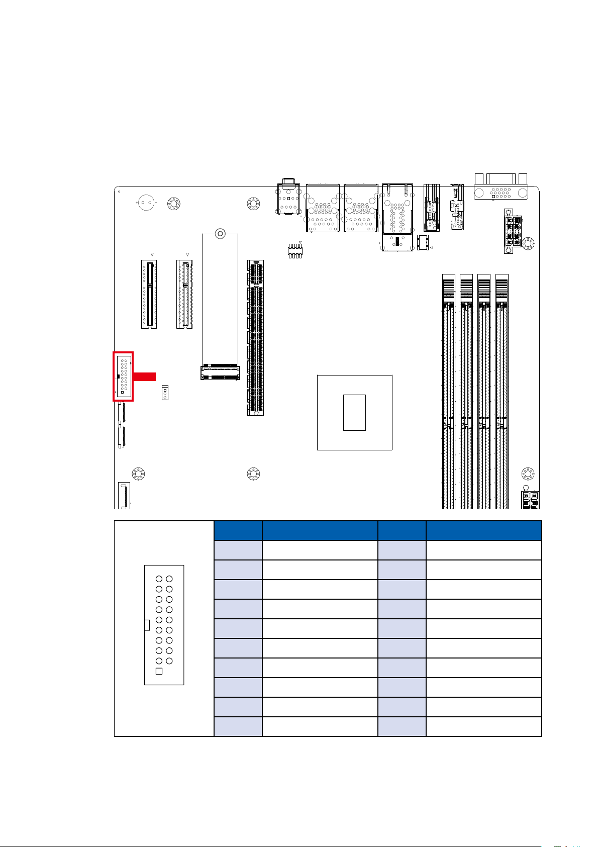
2.2.6 JUSB1, JUSB2 : Internal USB 2.0
4
1
1
5
6
10
11 15
1
A2B2A1
B1
A32
A31
B31
B32
A2B2A1
B1
A32
A31
B31
B32
146
1
146
1
146
146
1
1
4
8
7
1
2
8
7
1
2
12 345
22 25
U18
U14
U13
U10
U9
U5
U4
U1
R10
R9
R2
R1
L4
L3
L2L1
U18
U14
U13
U10
U9
U5
U4 U1
R10
R9
R2
R1
L4L3
L2
L1
R24
R12
R23
R11
R22
R10
R13
R1
L8
L5
L4
L1
B2
A2
A1
B1
The UMBC-1100 main board provides maxima eight expansion USB ports. The
USB interface supports 480Mbps transfer rate which comply with high speed
USB specication Rev. 2.0.
The USB interface is accessed through one 10-pin JST 1.0mm connector. You
will need an adapter cable if you use a standard USB connector. The adapter
cable has a 10-pin connector on one end and a USB connector on the other.
The pin assignments of JUSB1 and JUSB2 are listed in the following table :
11
11019
10
JUSB2
10
JUSB1
1
B81
A81
A82
B82
220
77
222
79
220
220
77
77
220
77
79
222
222
222
79
79
143
1
7 1
7 1
10
1
4
2
1
1
10
14
14
Pin No. Defnition
7
7
7 1
2
1
1
1
7
7
1
8
2
10
71
8
8
2
2
1
7
1
7
1
110 1
10
143
2
8
1
7
1
10
143
143
288
288
30
20
2
8
8
1
1
7
7
1
10
288
288
24
12
2
11
14 14
12
1 USB +VCC(+V5/Max. 0.5A)
2 USB +VCC(+V5/Max. 0.5A)
3 USB +VCC(+V5/Max. 0.5A)
10
4 DATA0-
5 DATA0+
1
6 DATA1-
7 DATA1+
8 Ground
9 Ground
©Vecow UMBC-1100 User Manual
10 Ground
GETTING TO KNOW YOUR UMBC-1100
14
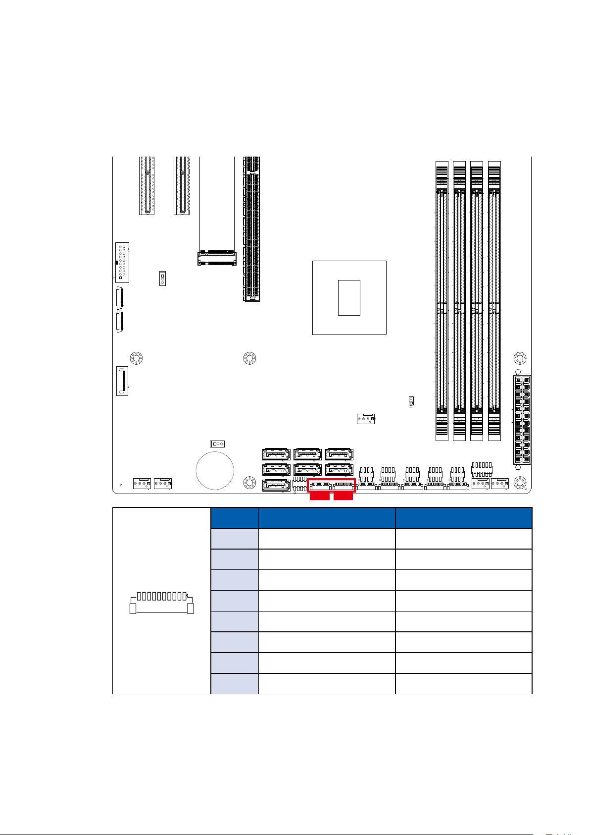
2.2.7 JUSB3 : Internal USB 3.1
1
There are 2 USB 3.1 connections available supporting up to 5GB per second
data rate in the top side of UMBC-1100. They are also compliant with the
requirements of SuperSpeed (SS), high speed (HS), full speed (FS) and low
speed (LS).
11 15
10
6
5
1
1
4
1
1
146
146
146
11
JUSB3
12 345
U4 U1
U5
U13
22 25
A2B2A1
B1
A2B2A1
B1
A32
A31
B31
B32
A32
A31
B31
B32
B1
A1
A2
B2
U14
1
R1
4
R2
L1
L2
1
7
2
8
U4
U1
L5
U9
U5
U9
U13
U10
U18
R9
R10
L4L3
U10
U18
U14
R1
R9
R2
L2L1
L3
L8
L1
L4
R1
R13
R10
L4
R10
R22
7
8
R11
R23
R12
R24
2
1
1
146
11019
10
10
1
B81
A81
A82
B82
220
77
222
79
220
220
77
77
220
77
79
222
222
222
79
79
Pin No. Defnition Pin No. Defnition
1 +V5/Max. 1.5A 2 RX1-
3 RX1+ 4 Ground
10
11
5 TX1- 6 TX1+
7 Ground 8 DATA1-
9 DATA1+ 10 NC
11 DATA2+ 12 DATA2-
19
1
13 Ground 14 TX2+
15 TX2- 16 Ground
©Vecow UMBC-1100 User Manual
17 RX2+ 18 RX2-
19 +V5/Max. 1.5A
GETTING TO KNOW YOUR UMBC-1100
15
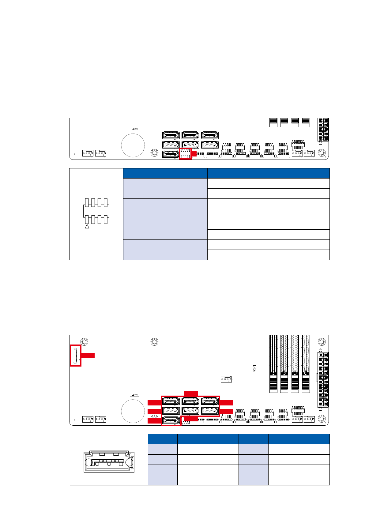
2.2.8 JDIO1, JDIO2 : GPIO Header
4
1
1
5
6
10
11 15
1
A2B2A1
B1
A2B2A1
B1
1
4
8
7
1
2
8
7
1
2
12 345
22 25
U18
U14
U13
U10
U9
U5
U4
U1
R10
R9
R2
R1
L4
L3
L2L1
U18
U14
U13
U10
U9
U5
U4 U1
R10
R9
R2
R1
L4L3
L2
L1
R24
R12
R23
R11
R22
R10
R13
R1
L8
L5
L4
L1
B2
A2
A1
B1
There is a 16-bit GPIO connector on the top side. Each GPIO channel can be
conguration GPI or GPO. Please refer to below table to see the pin denition in
details. JDIO1 and JDIO2 Pin dene are as below :
1
1
146
A32
A31
B31
B32
11
11019
10
10
1
A32
A31
B31
B32
B81
A81
A82
B82
220
77
77
222
79
79
1
146
146
220
222
146
220
77
220
77
79
222
222
79
143
1
4
14
14
7
7
7 1
2
7 1
1
1
1
7
7
2
7 1
1
8
10
10
1
71
JDIO2 JDIO1
8
2
1
1
10
8
2
2
1
7
1
7
1
110 1
10
143
2
8
1
7
1
10
143
143
288
288
30
20
2
8
8
1
1
7
7
1
10
288
288
24
12
2
11
14 14
12
Pin No. JDIO1 Denition JDIO2 Denition
1 SIO_GPI80 SIO_GPI84
2 SIO_GPI81 SIO_GPI85
110
3 SIO_GPI82 SIO_GPI86
4 SIO_GPI83 SIO_GPI87
5 SIO_GPO70 SIO_GPO74
6 SIO_GPO71 SIO_GPO75
7 SIO_GPO72 SIO_GPO76
8 SIO_GPO73 SIO_GPO77
©Vecow UMBC-1100 User Manual
GETTING TO KNOW YOUR UMBC-1100
16
4
1
1
5
6
10
11 15
11019
11
1
A2B2A1
B1
A32
A31
B31
B32
A2B2A1
B1
A32
A31
B31
B32
146
1
146
1
146
146
1
1
4
8
7
1
2
8
7
1
2
10
12 345
22 25
U18
U14
U13
U10
U9
U5
U4
U1
R10
R9
R2
R1
L4
L3
L2L1
U18
U14
U13
U10
U9
U5
U4 U1
R10
R9
R2
R1
L4L3
L2
L1
R24
R12
R23
R11
R22
R10
R13
R1
L8
L5
L4
L1
B2
A2
A1
B1
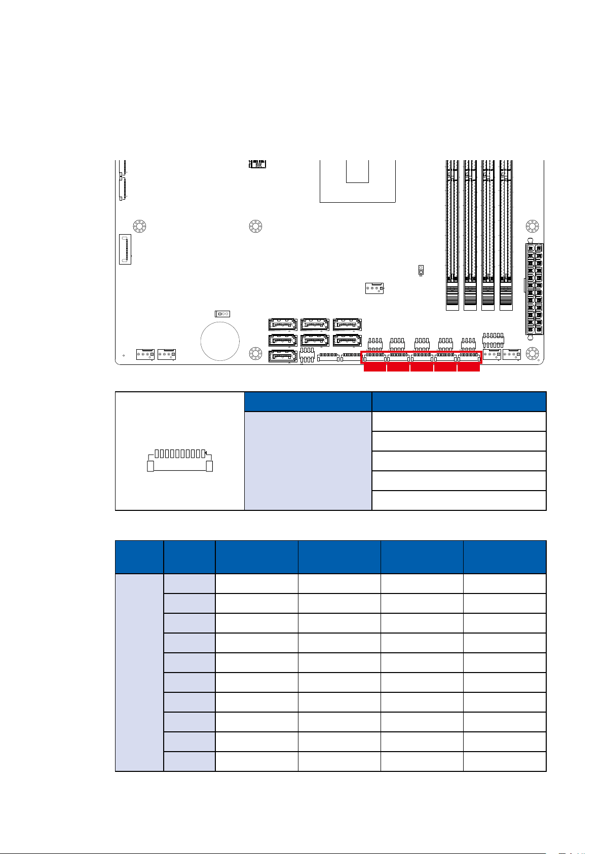
2.2.9 JCOM1 ~ JCOM5 : COM Port Header
Serial port 1 to 5 (JCOM 1 to 5) can be congured for RS-232, RS-422, or RS-485
with auto ow control communication. The default denition of COM 1 to 5 is RS-232,
if you want to change to RS-422 or RS-485, you can nd the setting in BIOS.
B81
A81
A82
B82
10
1
1
4
2
7 1
1
7
1
7
7 1
14
14
1
7
7
2
7 1
1
8
10
10
1
71
8
2
1
1
10
8
2
2
1
7
1
7
1
110 1
10
JCOM1 JCOM2 JCOM3 JCOM4 JCOM5
220
77
222
79
143
288
20
2
2
8
8
1
1
7
7
1
10
1
10
220
220
77
77
220
77
79
222
222
222
79
79
143
143
143
288
30
8
1
7
288
288
24
12
2
11
14 14
12
BIOS Setting Function
110
COM1 (JCOM1)
COM2 (JCOM2)
COM3 (JCOM3)
COM4 (JCOM4)
COM5 (JCOM5)
RS-485 w/z auto-ow control
RS-232
RS-422 (5-wire)
RS-422 (9-wire)
RS-485
The pin assignments are listed in the following table :
Serial
Port
Pin No. RS-232
RS-422
(5-wire)
1 GND_EARTH GND_EARTH GND_EARTH GND_EARTH
2 GND GND GND GND
3 RI ----------- CTS- RI
1, 2
3, 4, 5
4 DTR RXD- RXD- -----------
5 CTS ----------- CTS+ -----------
6 TXD RXD+ RXD+ -----------
RS-422
(9-wire)
RS-485
(3-wire)
7 RTS ----------- RTS+ -----------
8 RXD TXD+ TXD+ DATA +
9 DSR ----------- RTS- -----------
10 DCD TXD- TXD- DATA -
©Vecow UMBC-1100 User Manual
GETTING TO KNOW YOUR UMBC-1100
17
 Loading...