


USER
USER
SPC-3000/3500
Intel® Core™ i7/i5/i3 SoC (Skylake-U) Ultra-Compact Fanless
Embedded System, 4 GigE LAN, 4 USB 3.0, 9 COM, SUMIT, -40°C to 85°C
Manual
Manual
1.2.0 Edition 20171002

Record of Revision
Version Date Page Description Remark
0.1 08/10/2016 All Preliminary Release
1.0 10/21/2016 All Ofcial Release
1.1 07/20/2017 96-97 Update
1.2 10/02/2017 90-91 Update
ii

Disclaimer
This manual is released by Vecow Co., Ltd. for reference purpose only. All
product offerings and specications are subject to change without prior notice.
It does not represent commitment of Vecow Co., Ltd. Vecow shall not be liable
for direct, indirect, special, incidental, or consequential damages arising out of
the use of the product or documentation or any infringements upon the rights of
third parties, which may result from such use.
Declaration of Conformity
FCC
CE
This equipment has been tested and found to comply with the limits for a Class
A digital device, pursuant to part 15 of the FCC Rules. These limits are designed
to provide reasonable protection against harmful interference when the
equipment is operated in a commercial environment. This equipment generates,
uses, and can radiate radio frequency energy, and if it is not installed and used
in accordance with the instruction manual, it may cause harmful interference to
radio communications. Operation of this equipment in a residential area is likely
to cause harmful interference in which case the user will be required to correct
the interference at his own expense.
The products described in this manual complies with all applicable European
Union (CE) directives if it has a CE marking. For computer systems to
remain CE compliant, only CE-compliant parts may be used. Maintaining CE
compliance also requires proper cable and cabling techniques.
Copyright and Trademarks
This document contains proprietary information protected by copyright. No part
of this publication may be reproduced in any form or by any means, electric,
photocopying, recording or otherwise, without prior written authorization
by Vecow Co., Ltd. The rights of all the brand names, product names, and
trademarks belong to their respective owners.
iii
Order Information
Part Number Description
SPC-3010-600U
SPC-3010-300U
SPC-3010-955U
SPC-3020-600U
SPC-3020-300U
SPC-3020-955U
SPC-3030-600U
SPC-3000, onboard Intel
®
Core™ i7-6600U, 2 GigE LAN, 1 SSD,
4 USB 3.0, 2 COM, 1 SIM
SPC-3000, onboard Intel
®
Core™ i5-6300U, 2 GigE LAN, 1 SSD,
4 USB 3.0, 2 COM, 1 SIM
SPC-3000, onboard Intel
®
Celeron® 3955U, 2 GigE LAN, 1 SSD,
4 USB 3.0, 2 COM, 1 SIM
SPC-3000, onboard Intel
®
Core™ i7-6600U, 4 GigE LAN, 1 SSD,
4 USB 3.0, 5 COM, 1 SIM, 16 Isolated DIO
SPC-3000, onboard Intel
®
Core™ i5-6300U, 4 GigE LAN, 1 SSD,
4 USB 3.0, 5 COM, 1 SIM, 16 Isolated DIO
SPC-3000, onboard Intel
®
Celeron® 3955U, 4 GigE LAN, 1 SSD,
4 USB 3.0, 5 COM, 1 SIM, 16 Isolated DIO
SPC-3000, onboard Intel
®
Core™ i7-6600U, 4 GigE LAN, 2 SSD,
4 USB 3.0, 9 COM, 1 SIM, 16 Isolated DIO
SPC-3510-600U
SPC-3510-300U
SPC-3510-955U
SPC-3520-600U
SPC-3520-300U
SPC-3520-955U
SPC-3530-600U
SPC-3500, onboard Intel
®
Core™ i7-6600U, 2 GigE LAN, 1 SSD,
4 USB 3.0, 2 COM, 1 SIM
SPC-3500, onboard Intel
®
Core™ i5-6300U, 2 GigE LAN, 1 SSD,
4 USB 3.0, 2 COM, 1 SIM
SPC-3500, onboard Intel
®
Celeron® 3955U, 2 GigE LAN, 1 SSD,
4 USB 3.0, 2 COM, 1 SIM
SPC-3500, onboard Intel
®
Core™ i7-6600U, 4 GigE LAN, 1 SSD,
4 USB 3.0, 5 COM, 1 SIM, 16 Isolated DIO
SPC-3500, onboard Intel
®
Core™ i5-6300U, 4 GigE LAN, 1 SSD,
4 USB 3.0, 5 COM, 1 SIM, 16 Isolated DIO
SPC-3500, onboard Intel
®
Celeron® 3955U, 4 GigE LAN, 1 SSD,
4 USB 3.0, 5 COM, 1 SIM, 16 Isolated DIO
SPC-3500, onboard Intel
®
Core™ i7-6600U, 4 GigE LAN, 2 SSD,
4 USB 3.0, 9 COM, 1 SIM, 16 Isolated DIO
iv
Order Accessories
Part Number Description
DDR4 16G
DDR4 8G
DDR4 4G
PWA-120W 120W, 24V, 90V AC to 264V AC Power Adapter with 3-pin
PWA-160W-WT 160W, 24V, 85V AC to 264V AC Power Adaptor with 3-pin
TMK2-20P-100
TMK2-20P-500
TMB-TMBK-20P Terminal Board with One 20-pin Terminal Block Connector
VESA Mount
DIN-RAIL
Rack Mount
3G Module
Certied DDR4 16GB 2133MHz RAM
Certied DDR4 8GB 2133MHz RAM
Certied DDR4 4GB 2133MHz RAM
Terminal Block
Terminal Block, Wide Temperature -30°C to +70°C
Terminal Block 20-pin to Terminal Block 20-pin Cable, 100cm
Terminal Block 20-pin to Terminal Block 20-pin Cable, 500cm
and DIN-Rail Mounting
VESA Mounting Kit
DIN Rail Kit
1U Rackmount/ 2U Rackmount
Mini PCIe 3G/GPS Module with Antenna
4G Module
WiFi & Bluetooth
Module
Mini PCIe 4G/GPS Module with Antenna
Mini PCIe WiFi & Bluetooth Module with Antenna
v

Table of Contents
CHAPTER 1 GENERAL INTRODUCTION 1
1.1 Overview 1
1.2 Features 2
1.3 Product Specication 2
1.3.1 Specications of SPC-3010 2
1.3.2 Specications of SPC-3020 4
1.3.3 Specications of SPC-3030 6
1.3.4 Specications of SPC-3510 8
1.3.5 Specications of SPC-3520 10
1.3.6 Specications of SPC-3530 12
1.4 Supported CPU List 14
1.5 Mechanical Dimension 14
1.5.1 Dimensions of SPC-3000 14
1.5.1 Dimensions of SPC-3500 14
CHAPTER 2 GETTING TO KNOW YOUR SPC-3000/3500 15
2.1 Packing List 15
2.2 Front Panel I/O Functions 16
2.2.1 SPC-3010 Front I/O & Functions 16
2.2.2 SPC-3020 Front I/O & Functions 20
2.2.3 SPC-3030 Front I/O & Functions 27
2.2.4 SPC-3510 Front I/O & Functions 34
2.2.5 SPC-3520 Front I/O & Functions 40
2.2.6 SPC-3530 Front I/O & Functions 47
2.3 Rear Panel I/O Functions 56
2.3.1 SPC-3010 Rear I/O & Functions 56
2.3.2 SPC-3020 Rear I/O & Functions 57
2.3.3 SPC-3030 Rear I/O & Functions 61
2.3.4 SPC-3510 Rear I/O & Functions 65
2.3.5 SPC-3520 Rear I/O & Functions 66
2.3.6 SPC-3530 Rear I/O & Functions 70
2.4 Main Board Expansion Connectors 74
2.5 Main Board Jumper Settings 95
vi

CHAPTER 3 SYSTEM SETUP 98
3.1 How to Open Your SPC-3000/3500 98
3.2 Installing DDR4 SO-DIMM Modules 100
3.3 Installing Mini PCIe Card 101
3.4 Installing Antenna Cable 102
3.5 Installing SIM Card 103
3.6 Installing SSD/HDD 104
3.7 Mounting Your SPC-3000/3500 106
CHAPTER 4 BIOS SETUP 107
4.1 Entering Setup 107
4.2 Main Menu 108
4.3 Advanced Function 108
4.4 Chipset 119
4.5 Security 124
4.6 Boot 125
4.7 Save & Exit 126
APPENDIX A : ISOLATED DIO GUIDE 127
APPENDIX B : GPIO & WDT Functions 131
APPENDIX C : RAID Installation Guide 132
APPENDIX D : Power Consumption 136
vii

1
GENERAL INTRODUCTION
1.1 Overview
SPC-3000/3500 is a series of rugged Ultra-compact Fanless Embedded Box
PC. Powered by 6th generation Intel® Core™ i7/i5/i3 processor (Skylake-U),
dual channel DDR4 2133MHz up to 16GB memory, SPC-3000/3500 serves
up to 10% CPU performance enhances than the former generation Intel® SoC
solution with lower CPU power consumption; Advanced Intel
graphics engine supports DirectX 12, OpenGL 4.4 and OpenCL 2.0 API, DVI-I
and DisplayPort interfaces support up to ultra HD 4K resolution, SPC-3000/3500
offers up to 34% improved graphics performance than the former generation.
Multiple Gen 3 PCIe (8GT/s), SATA III (6Gbps), USB 3.0 (5Gbps), PoE (1Gbps)
LAN and exible 3G/ 4G/ WiFi/ LTE/ GPS/ GPRS/ UMTS wireless connections
make high-speed data conveying possible. Vecow SPC-3000/3500 Series Ultracompact Fanless Embedded System delivers you outstanding Power-Efcient
Performance for demanding workloads.
®
HD Graphics 520
Featured with 2 independent Gigabit LANs support iAMT 11.0, 2 COM RS232/ 422/ 485, 4 external USB 3.0, 4 USB 2.0, 2 Mini PCIe sockets, 1 SIM card
socket for 3G/ 4G/ LTE/ WiFi/ GPRS/ UMTS, 2 SATA III and 16 GPIO, 9V to 36V
wide range power input, fanless -40°C to 85°C operating temperature, smart
manageability features, all-in-one and cable-less designs, SPC-3000/3500 is
your compact embedded engine.
Onboard SUMIT A, B connection supports up to 5 GigE LAN connections,
up to 9 COM RS-232/422/485 expansions, 10GB LAN data delivery or any
customized expansion function for your application, Vecow SPC-3000/3500
Series Ultra-compact Fanless Embedded System integrates outstanding
performance, remarkable power productivity, smart manageability, mobile
availability, versatile expandability, industrial-grade reliability and all-in-one
compact solution for low-prole performance driven embedded applications.
Vecow SPC-3000/3500 Series Ultra-compact Fanless Embedded System
delivers outstanding performance, compact integrated functions, smart
manageability, mobile availability, trusted reliability and flexible expansion
features for your Healthcare Service, Smart Automation, Point-Of-Information
(POI), Self-Services, In-vehicle Infotainment, Industry 4.0 and any performance
driven compact Internet of Things (IoT) applications.
GENERAL INTRODUCTION
1
1.2 Features
• 6th Generation Intel® Core™ i7/ i5/ i3 U-series Processor (Skylake-U)
• DDR4 2133MHz memory, up to 16GB
• Fanless, -40°C to 85°C Operating Temperature
• Onboard DisplayPort and DVI-D display interfaces support up to 4K display
• 2 Independent GigE LAN, iAMT 11.0 supported
• 2 Mini PCIe Socket for 3G/ 4G/ LTE/ WiFi/ GPRS/ UMTS
• 4 USB 3.0, 1 SIM Socket, 1 SSD, 2 COM RS-232/422/485, 16 GPIO
• Supports Full function SUMIT A, B expansion : Up to 5 Independent GigE LAN,
up to 9 COM RS-232/422/485, up to 4 SIM Socket or fiber connections
• 9V to 36V DC Power Input, 16 Isolated DIO
• Easy to customize for low-profile system applications
• One-stop SUMIT Expansion Design and Manufacturing Services
1.3 Product Specication
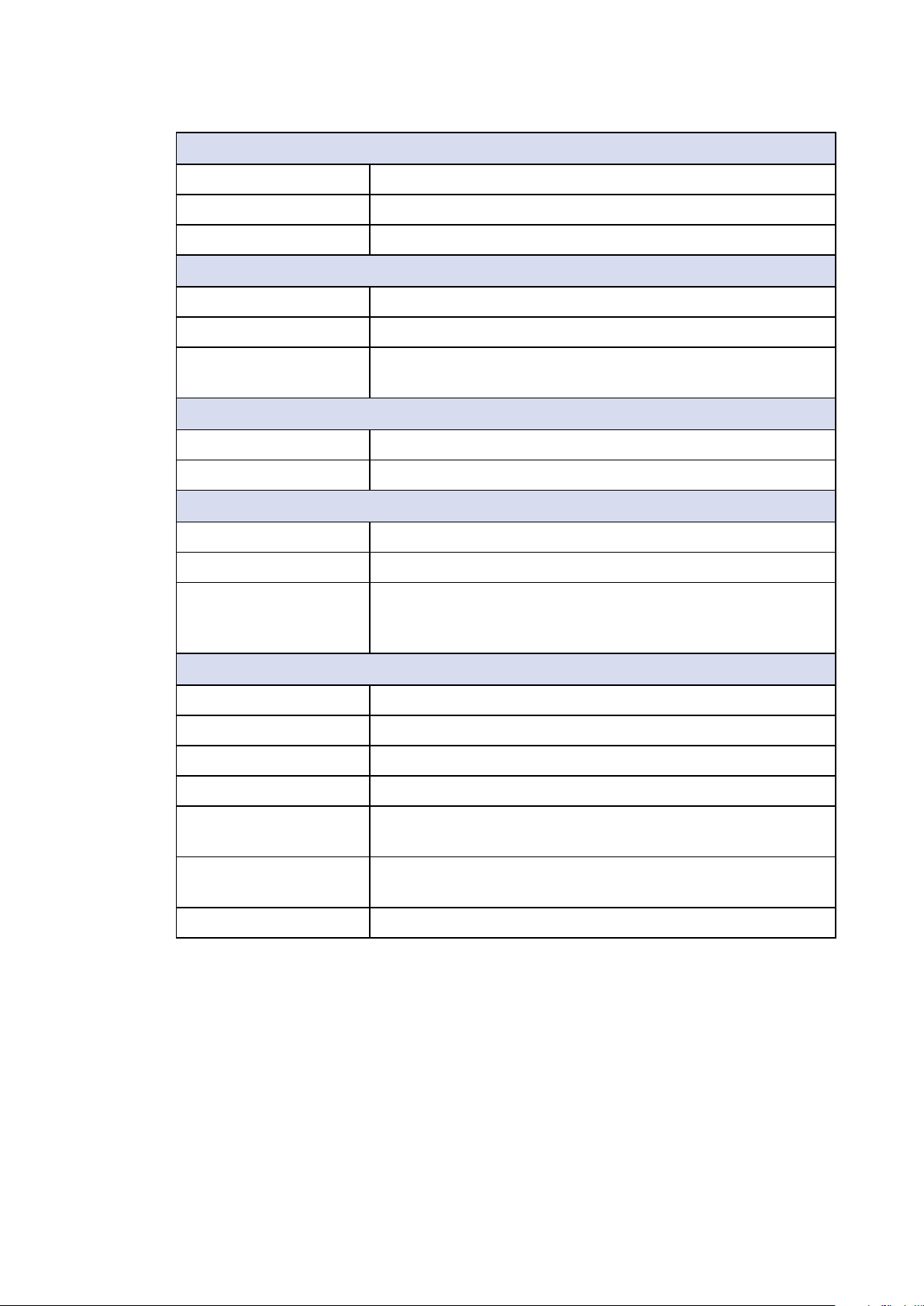
1.3.1 Specications of SPC-3010
System
Processor Intel® Core™ i7-6600U/ i5-6300U/ Celeron® 3955U
Processor (Skylake-U)
Chipset Intel
BIOS AMI
SIO IT8786E
Memory 1 DDR4 2133MHz SO-DIMM, up to 16GB
®
SoC (Skylake)
I/O Interface
Serial 2 COM RS-232/ 422/ 485
USB 3.0 4 USB 3.0 (External)
USB 2.0 SPC-3010-600U, SPC-3010-300U : 4 USB 2.0 (Internal)
SPC-3010-955U : 2 USB 2.0 (Internal)
GPIO 16 GPIO (Internal)
LED Power, HDD
SIM Card 1 SIM Card Socket (Internal)
Expansion
Mini PCIe 2 Mini PCIe Socket :
SUMIT A, B • 1 SUMIT Connector A (Internal, optional)
©Vecow SPC-3000/3500 User Manual
• 1 Full-size for PCIe/ USB/ Internal SIM Card
• 1 Full-size for PCIe/ USB/ mSATA
• 1 SUMIT Connector B (Internal, optional)
GENERAL INTRODUCTION
2
Graphics
Graphics Processor Intel® HD Graphics 520
Interface • DVI-D : Up to 1920 x 1200
• DisplayPort : Up to 4096 x 2304
Storage
SATA 2 SATA III (6Gbps)
mSATA 1 SATA III (Mini PCIe Type, 6Gbps)
Storage Device 1 2.5" SSD/ HDD Bracket (Internal)
Audio
Audio Codec Realtek ALC892, 5.1 Channel HD Audio
Audio Interface 1 Mic-in, 1 Line-out
Ethernet
LAN 1 Intel® I219 Gigabit LAN supports iAMT 11.0
LAN 2 Intel
®
I210 Gigabit LAN
Power
Power Input 9V to 36V, DC-in
Power Interface 3-pin Terminal Block : V+, V-, Frame Ground
Remote Switch 2-pin Terminal Block : On, Off
Others
Watchdog Timer Reset : 1 to 255 sec./min. per step
Smart Management Wake on LAN, PXE supported
HW Monitor Monitoring temperature, voltages. Auto throttling control
when CPU overheats.
Software Support
Microsoft Windows 10, Windows 8.1, Windows 7
Linux Fedora 19, Ubuntu 10.04 LTS, or Linux Kernel 3.0 above
Mechanical
Dimensions (WxLxH) 150mm x 106mm x 44mm (5.9” x 4.2” x 1.7”)
Weight 0.9 kg (1.98 lb)
Mounting • Wallmount by mounting bracket
• DIN Rail Mount (Optional)
• 1U Rackmount (Optional)
Environment
Operating Temperature -40°C to 70°C (-40°F to 158°F)
Storage Temperature -40°C to 85°C (-40°F to 185°F)
Humidity 5% to 95% Humidity, non-condensing
GENERAL INTRODUCTION
3
Relative Humidity 95% at 70°C
Shock • IEC 60068-2-27
• SSD : 50G @ Wallmount, Half-sine, 11ms
Vibration • IEC 60068-2-64
• SSD : 5Grms, 5Hz to 500Hz, 3 Axis
EMC CE, FCC, EN 50155, EN 50121-3-2
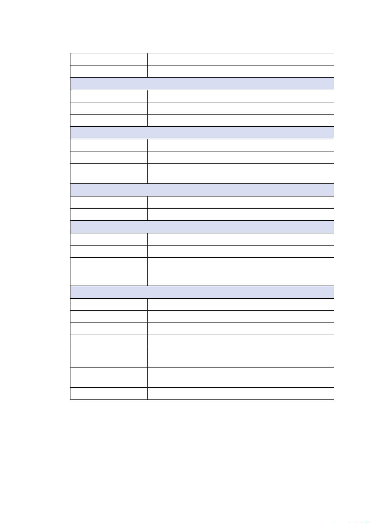
1.3.2 Specications of SPC-3020
System
Processor Intel® Core™ i7-6600U/ i5-6300U/ Celeron® 3955U
Processor (Skylake-U)
Chipset Intel
BIOS AMI
SIO IT8786E
®
SoC (Skylake)
Memory 1 DDR4 2133MHz SO-DIMM, up to 16GB
I/O Interface
Serial 2 COM RS-232/ 422/ 485
USB 3.0 4 USB 3.0 (External)
USB 2.0 SPC-3020-600U, SPC-3020-300U : 4 USB 2.0 (Internal)
SPC-3020-955U : 2 USB 2.0 (Internal)
Isolated DIO 16 Isolated DIO : 8 DI, 8 DO
LED Power, HDD
SIM Card 1 SIM Card Socket (Internal)
Expansion
Mini PCIe 2 Mini PCIe Socket :
• 1 Full-size for PCIe/ USB/ Internal SIM Card
• 1 Full-size for PCIe/ USB/ mSATA
SUMIT A, B • 1 SUMIT Connector A (Internal, optional)
• 1 SUMIT Connector B (Internal, optional)
Graphics
Graphics Processor Intel® HD Graphics 520
Interface • DVI-D : Up to 1920 x 1200
Storage
SATA 2 SATA III (6Gbps)
mSATA 1 SATA III (Mini PCIe Type, 6Gbps)
©Vecow SPC-3000/3500 User Manual
• DisplayPort : Up to 4096 x 2304
GENERAL INTRODUCTION
4
Storage Device 1 2.5" SSD/ HDD Bracket (Internal)
Audio
Audio Codec Realtek ALC892, 5.1 Channel HD Audio
Audio Interface 1 Mic-in, 1 Line-out
Ethernet
LAN 1 Intel® I219LM Gigabit LAN supports iAMT 11.0
LAN 2 Intel
LAN 3 Intel
LAN 4 Intel
®
I210 Gigabit LAN
®
I210 Gigabit LAN
®
I210 Gigabit LAN
Power
Power Input 9V to 36V, DC-in
Power Interface 3-pin Terminal Block : V+, V-, Frame Ground
Remote Switch 2-pin Terminal Block : On, Off
Others
Watchdog Timer Reset : 1 to 255 sec./min. per step
Smart Management Wake on LAN, PXE supported
HW Monitor Monitoring temperature, voltages. Auto throttling control
when CPU overheats.
Software Support
Microsoft Windows 10, Windows 8.1, Windows 7
Linux Fedora 19, Ubuntu 10.04 LTS, or Linux Kernel 3.0 above
Mechanical
Dimensions (WxLxH) 150mm x 106mm x 68mm (5.9” x 4.2” x 2.7”)
Weight 1.3 kg (2.87 lb)
Mounting • Wallmount by mounting bracket
• DIN Rail Mount (Optional)
• 2U Rackmount (Optional)
Environment
Operating Temperature -40°C to 70°C (-40°F to 158°F)
Storage Temperature -40°C to 85°C (-40°F to 185°F)
Humidity 5% to 95% Humidity, non-condensing
Relative Humidity 95% at 70°C
Shock • IEC 60068-2-27
• SSD : 50G @ Wallmount, Half-sine, 11ms
Vibration • IEC 60068-2-64
• SSD : 5Grms, 5Hz to 500Hz, 3 Axis
EMC CE, FCC, EN 50155, EN 50121-3-2
GENERAL INTRODUCTION
5
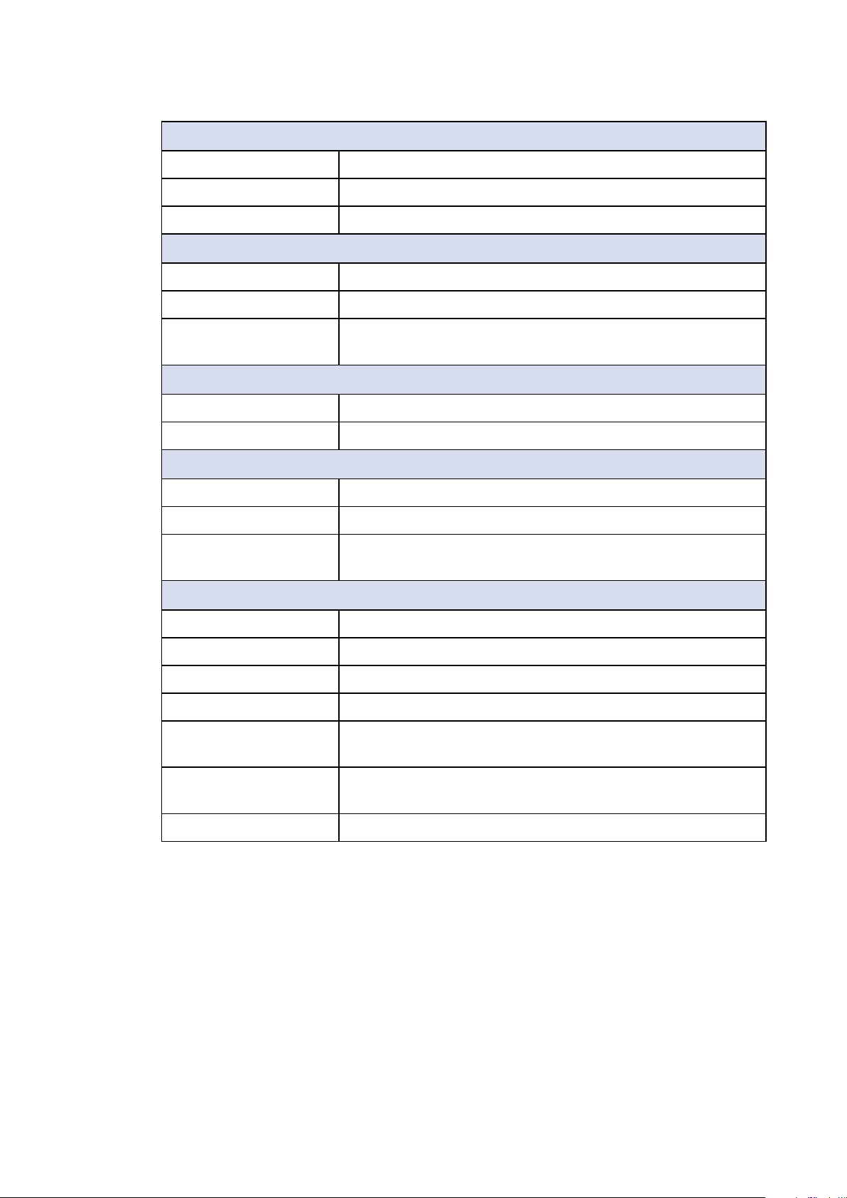
1.3.3 Specications of SPC-3030
System
Processor Intel® Core™ i7-6600U Processor (Skylake-U)
Chipset Intel
BIOS AMI
SIO IT8786E
Memory 1 DDR4 2133MHz SO-DIMM, up to 16GB
I/O Interface
Serial 9 COM RS-232/ 422/ 485
USB • 4 USB 3.0 (External)
Isolated DIO 16 Isolated DIO : 8 DI, 8 DO
LED Power, HDD
SIM Card 1 SIM Card Socket (Internal)
Expansion
®
SoC (Skylake)
• 4 USB 2.0 (Internal)
Mini PCIe 2 Mini PCIe Socket :
• 1 Full-size for PCIe/ USB/ Internal SIM Card
• 1 Full-size for PCIe/ USB/ mSATA
SUMIT A, B • 1 SUMIT Connector A (Internal, optional)
• 1 SUMIT Connector B (Internal, optional)
Graphics
Graphics Processor Intel® HD Graphics 520
Interface • DVI-D : Up to 1920 x 1200
• DisplayPort : Up to 4096 x 2304
Storage
SATA 2 SATA III (6Gbps)
mSATA 1 SATA III (Mini PCIe Type, 6Gbps)
Storage Device 1 2.5" SSD/ HDD Bracket (Internal)
Audio
Audio Codec Realtek ALC892, 5.1 Channel HD Audio
Audio Interface 1 Mic-in, 1 Line-out
Ethernet
LAN 1 Intel® I219LM Gigabit LAN supports iAMT 11.0
LAN 2 Intel
LAN 3 Intel
LAN 4 Intel
©Vecow SPC-3000/3500 User Manual
®
I210 Gigabit LAN
®
I210 Gigabit LAN
®
I210 Gigabit LAN
GENERAL INTRODUCTION
6

Power
Power Input 9V to 36V, DC-in
Power Interface 3-pin Terminal Block : V+, V-, Frame Ground
Remote Switch 2-pin Terminal Block : On, Off
Others
Watchdog Timer Reset : 1 to 255 sec./min. per step
Smart Management Wake on LAN, PXE supported
HW Monitor Monitoring temperature, voltages. Auto throttling control
when CPU overheats.
Software Support
Microsoft Windows 10, Windows 8.1, Windows 7
Linux Fedora 19, Ubuntu 10.04 LTS, or Linux Kernel 3.0 above
Mechanical
Dimensions (WxLxH) 150mm x 106mm x 82mm (5.9” x 4.2” x 3.2”)
Weight 1.7 kg (3.75 lb)
Mounting • Wallmount by mounting bracket
• DIN Rail Mount (Optional)
Environment
Operating Temperature -40°C to 70°C (-40°F to 158°F)
Storage Temperature -40°C to 85°C (-40°F to 185°F)
Humidity 5% to 95% Humidity, non-condensing
Relative Humidity 95% at 70°C
Shock • IEC 60068-2-27
• SSD : 50G @ Wallmount, Half-sine, 11ms
Vibration • IEC 60068-2-64
• SSD : 5Grms, 5Hz to 500Hz, 3 Axis
EMC CE, FCC, EN 50155, EN 50121-3-2
GENERAL INTRODUCTION
7
1.3.4 Specications of SPC-3510
System
Processor Intel® Core™ i7-6600U/ i5-6300U/ Celeron® 3955U
Processor (Skylake-U)
Chipset Intel
BIOS AMI
SIO IT8786E
Memory 1 DDR4 2133MHz SO-DIMM, up to 16GB
I/O Interface
Serial 2 COM RS-232/ 422/ 485
USB 3.0 4 USB 3.0 (External)
®
SoC (Skylake)
USB 2.0
SPC-3510-600U, SPC-3510-300U : 4 USB 2.0 (Internal)
SPC-3510-955U : 2 USB 2.0 (Internal)
GPIO 16 GPIO (Internal)
LED Power, HDD
SIM Card 1 SIM Card Socket (Internal)
Expansion
Mini PCIe 2 Mini PCIe Socket :
• 1 Full-size for PCIe/ USB/ Internal SIM Card
• 1 Full-size for PCIe/ USB/ mSATA
SUMIT A, B • 1 SUMIT Connector A (Internal, optional)
• 1 SUMIT Connector B (Internal, optional)
Graphics
Graphics Processor Intel® HD Graphics 520
Interface • DVI-D : Up to 1920 x 1200
• DisplayPort : Up to 4096 x 2304
Storage
SATA 2 SATA III (6Gbps)
mSATA 1 SATA III (Mini PCIe Type, 6Gbps)
Storage Device 1 2.5" SSD/ HDD Bracket (Internal)
Audio
Audio Codec Realtek ALC892, 5.1 Channel HD Audio
Audio Interface 1 Mic-in, 1 Line-out
Ethernet
LAN 1 Intel® I219LM Gigabit LAN supports iAMT 11.0
LAN 2 Intel
©Vecow SPC-3000/3500 User Manual
®
I210 Gigabit LAN
GENERAL INTRODUCTION
8
Power
Power Input 9V to 36V, DC-in
Power Interface 3-pin Terminal Block : V+, V-, Frame Ground
Remote Switch 2-pin Terminal Block : On, Off
Others
Watchdog Timer Reset : 1 to 255 sec./min. per step
Smart Management Wake on LAN, PXE supported
HW Monitor Monitoring temperature, voltages. Auto throttling control
when CPU overheats.
Software Support
Microsoft Windows 10, Windows 8.1, Windows 7
Linux Fedora 19, Ubuntu 10.04 LTS, or Linux Kernel 3.0 above
Mechanical
Dimensions (WxLxH) 150mm x 106mm x 62mm (5.9” x 4.2” x 2.5”)
Weight 1.4 kg (3.08 lb)
Mounting • Wallmount by mounting bracket
• DIN Rail Mount (Optional)
• 2U Rackmount (Optional)
Environment
Operating Temperature -40°C to 85°C (-40°F to 185°F)
Storage Temperature -40°C to 85°C (-40°F to 185°F)
Humidity 5% to 95% Humidity, non-condensing
Relative Humidity 95% at 70°C
Shock • IEC 60068-2-27
• SSD : 50G @ Wallmount, Half-sine, 11ms
Vibration • IEC 60068-2-64
• SSD : 5Grms, 5Hz to 500Hz, 3 Axis
EMC CE, FCC, EN 50155, EN 50121-3-2
GENERAL INTRODUCTION
9

1.3.5 Specications of SPC-3520
System
Processor Intel® Core™ i7-6600U/ i5-6300U/ Celeron® 3955U
Processor (Skylake-U)
Chipset Intel
BIOS AMI
SIO IT8786E
Memory 1 DDR4 2133MHz SO-DIMM, up to 16GB
I/O Interface
Serial 2 COM RS-232/ 422/ 485
USB 3.0 4 USB 3.0 (External)
USB 2.0 SPC-3520-600U, SPC-3520-300U : 4 USB 2.0 (Internal)
Isolated DIO 16 Isolated DIO : 8 DI, 8 DO
LED Power, HDD
®
SoC (Skylake)
SPC-3520-955U : 2 USB 2.0 (Internal)
SIM Card 1 SIM Card Socket (Internal)
Expansion
Mini PCIe 2 Mini PCIe Socket :
• 1 Full-size for PCIe/ USB/ Internal SIM Card
• 1 Full-size for PCIe/ USB/ mSATA
SUMIT A, B • 1 SUMIT Connector A (Internal, optional)
• 1 SUMIT Connector B (Internal, optional)
Graphics
Graphics Processor Intel® HD Graphics 520
Interface • DVI-D : Up to 1920 x 1200
• DisplayPort : Up to 4096 x 2304
Storage
SATA 2 SATA III (6Gbps)
mSATA 1 SATA III (Mini PCIe Type, 6Gbps)
Storage Device 1 2.5" SSD/ HDD Bracket (Internal)
Audio
Audio Codec Realtek ALC892, 5.1 Channel HD Audio
Audio Interface 1 Mic-in, 1 Line-out
Ethernet
LAN 1 Intel® I219LM Gigabit LAN supports iAMT 11.0
LAN 2 Intel
©Vecow SPC-3000/3500 User Manual
®
I210 Gigabit LAN
GENERAL INTRODUCTION
10
LAN 3 Intel® I210 Gigabit LAN
LAN 4 Intel
®
I210 Gigabit LAN
Power
Power Input 9V to 36V, DC-in
Power Interface 3-pin Terminal Block : V+, V-, Frame Ground
Remote Switch 2-pin Terminal Block : On, Off
Others
Watchdog Timer Reset : 1 to 255 sec./min. per step
Smart Management Wake on LAN, PXE supported
HW Monitor Monitoring temperature, voltages. Auto throttling control
when CPU overheats.
Software Support
Microsoft Windows 10, Windows 8.1, Windows 7
Linux Fedora 19, Ubuntu 10.04 LTS, or Linux Kernel 3.0 above
Mechanical
Dimensions (WxLxH) 150mm x 106mm x 86mm (5.9” x 4.2” x 3.4”)
Weight 1.8 kg (3.97 lb)
Mounting • Wallmount by mounting bracket
• DIN Rail Mount (Optional)
• 2U Rackmount (Optional)
Environment
Operating Temperature -40°C to 85°C (-40°F to 185°F)
Storage Temperature -40°C to 85°C (-40°F to 185°F)
Humidity 5% to 95% Humidity, non-condensing
Relative Humidity 95% at 70°C
Shock • IEC 60068-2-27
• SSD : 50G @ Wallmount, Half-sine, 11ms
Vibration • IEC 60068-2-64
• SSD : 5Grms, 5Hz to 500Hz, 3 Axis
EMC CE, FCC, EN 50155, EN 50121-3-2
GENERAL INTRODUCTION
11

1.3.6 Specications of SPC-3530
System
Processor Intel® Core™ i7-6600U Processor (Skylake-U)
Chipset Intel
BIOS AMI
SIO IT8786E
Memory 1 DDR4 2133MHz SO-DIMM, up to 16GB
I/O Interface
Serial 9 COM RS-232/ 422/ 485
USB • 4 USB 3.0 (External)
Isolated DIO 16 Isolated DIO : 8 DI, 8 DO
LED Power, HDD
SIM Card 1 SIM Card Socket (Internal)
Expansion
®
SoC (Skylake)
• 4 USB 2.0 (Internal)
Mini PCIe 2 Mini PCIe Socket :
• 1 Full-size for PCIe/ USB/ Internal SIM Card
• 1 Full-size for PCIe/ USB/ mSATA
SUMIT A, B • 1 SUMIT Connector A (Internal, optional)
• 1 SUMIT Connector B (Internal, optional)
Graphics
Graphics Processor Intel® HD Graphics 520
Interface • DVI-D : Up to 1920 x 1200
• DisplayPort : Up to 4096 x 2304
Storage
SATA 2 SATA III (6Gbps)
mSATA 1 SATA III (Mini PCIe Type, 6Gbps)
Storage Device 2 2.5" SSD/ HDD Bracket (Internal)
Audio
Audio Codec Realtek ALC892, 5.1 Channel HD Audio
Audio Interface 1 Mic-in, 1 Line-out
Ethernet
LAN 1 Intel® I219LM Gigabit LAN supports iAMT 11.0
LAN 2 Intel
LAN 3 Intel
LAN 4 Intel
©Vecow SPC-3000/3500 User Manual
®
I210 Gigabit LAN
®
I210 Gigabit LAN
®
I210 Gigabit LAN
GENERAL INTRODUCTION
12
Power
Power Input 9V to 36V, DC-in
Power Interface 3-pin Terminal Block : V+, V-, Frame Ground
Remote Switch 2-pin Terminal Block : On, Off
Others
Watchdog Timer Reset : 1 to 255 sec./min. per step
Smart Management Wake on LAN, PXE supported
HW Monitor Monitoring temperature, voltages. Auto throttling control
when CPU overheats.
Software Support
Microsoft Windows 10, Windows 8.1, Windows 7
Linux Fedora 19, Ubuntu 10.04 LTS, or Linux Kernel 3.0 above
Mechanical
Dimensions (WxLxH) 150mm x 106mm x 100mm (5.9” x 4.2” x 3.9”)
Weight 2.1 kg (4.62 lb)
Mounting • Wallmount by mounting bracket
• DIN Rail Mount (Optional)
Environment
Operating Temperature -40°C to 85°C (-40°F to 185°F)
Storage Temperature -40°C to 85°C (-40°F to 185°F)
Humidity 5% to 95% Humidity, non-condensing
Relative Humidity 95% at 70°C
Shock • IEC 60068-2-27
• SSD : 50G @ Wallmount, Half-sine, 11ms
Vibration • IEC 60068-2-64
• SSD : 5Grms, 5Hz to 500Hz, 3 Axis
EMC CE, FCC, EN 50155, EN 50121-3-2
GENERAL INTRODUCTION
13
1.4 Supported CPU List
Processor No. TDP Cache Max. Frequency Embedded
i7-6600U 15W 4M Up to 3.40 GHz Yes
i5-6300U 15W 4M Up to 3.00 GHz Yes
i3-6100U 15W 4M Up to 2.30 GHz Yes
Celeron 3955U 15W 4M Up to 2.00 GHz Yes
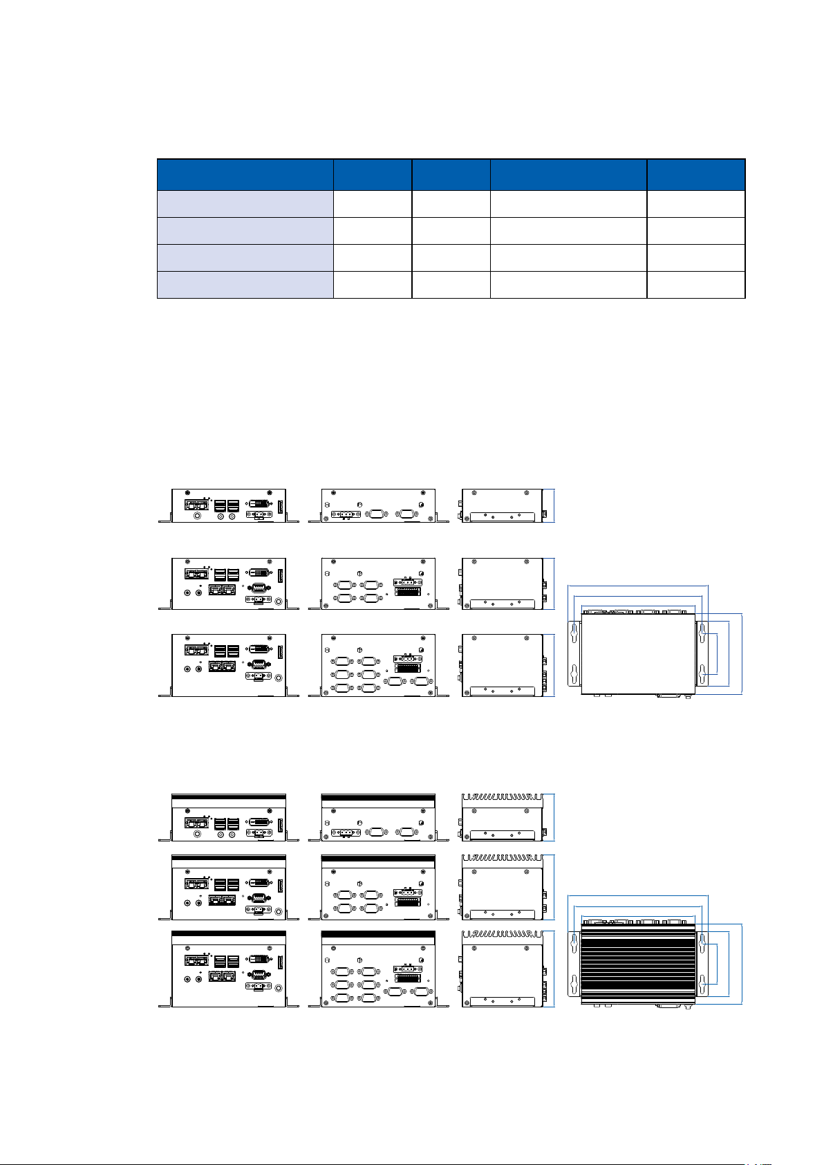
1.5 Mechanical Dimension
1.5.1 Dimensions of SPC-3000
1.5.1 Dimensions of SPC-3500
44.0 (1.73”)68.1 (2.68”)82.1 (3.23”)
61.9 (2.44”)86.0 (3.39”)100.0 (3.94”)
Unit: mm (inch)
185.4 (7.30”)
169.1 (6.66”)
150.4 (5.92”)
Unit: mm (inch)
53.8 (2.12”)
85.8 (3.38”)
106.2 (4.18”)
©Vecow SPC-3000/3500 User Manual
185.4 (7.30”)
169.1 (6.66”)
150.4 (5.92”)
GENERAL INTRODUCTION
53.8 (2.12”)
85.8 (3.38”)
14
106.2 (4.18”)
2
GETTING TO KNOW YOUR SPC-3000/3500
2.1 Packing List
Item Description Qty
1 SPC-3000/3500 Embedded System 1
2 Driver/ User Manual DVD 1
SPC-3010/3510
● Wall-mounting bracket
● Terminal block plug pitch 2.54mm 2x10-pin
● Terminal block plug pitch 5.0mm 3-pin
● Terminal block plug pitch 5.0mm 2-pin
3
● Foot Pad
● PH-M4x16.5 for Din Rail
● EPE
● Plastic Bag
● PH-M2.5x6 screws for MiniPCIe slot
● KH-M3x6 for SSD/HDD bracket and Wall-mount bracket
12
2
1
1
1
4
4
1
1
2
SPC-3020/3520
● Wall-mounting bracket
● Terminal block plug pitch 2.54mm 2x10-pin
● Terminal block plug pitch 5.0mm 3-pin
● Terminal block plug pitch 5.0mm 2-pin
4
5
● Foot Pad
● PH-M4x16.5 for Din Rail
● EPE
● Plastic Bag
● PH-M2.5x6 screws for MiniPCIe slot
● KH-M3x6 for SSD/HDD bracket and Wall-mount bracket
SPC-3030/3530
● Wall-mounting bracket
● Terminal block plug pitch 2.54mm 2x10-pin
● Terminal block plug pitch 5.0mm 3-pin
● Terminal block plug pitch 5.0mm 2-pin
● Foot Pad
● PH-M4x16.5 for Din Rail
● EPE
● Plastic Bag
● KH-M3x6 for SSD/HDD bracket and Wall-mount bracket
2
1
1
1
4
4
1
1
2
12
2
1
1
1
4
4
1
1
16
GETTING TO KNOW YOUR SPC-3000/3500
15
2.2 Front Panel I/O Functions
2.2.1 SPC-3010 Front I/O & Functions
In Vecow’s SPC-3000 series family, all I/O connectors are located on the front
panel. Most of the general connections to the computer device, such as audio,
USB, DVI-D, LAN Jack, and DisplayPort, are placed on the front panel.
LAN 1 LAN 2
Switch
DVI-D
On | Off
DP
2.2.1.1 Reset Tact Switch
DVI-D
On | Off
LAN 1 LAN 2
Switch
It is a hardware reset switch. Use this switch to reset the system without power
off the system. Press the Reset Switch for a few seconds, then reset will be
enabled.
DP
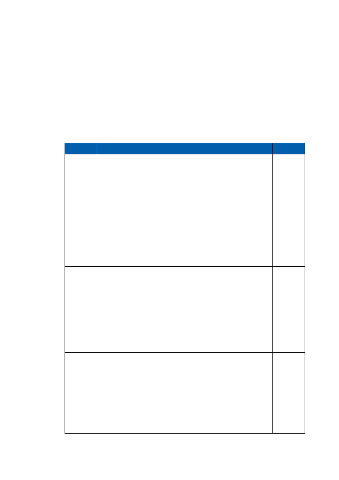
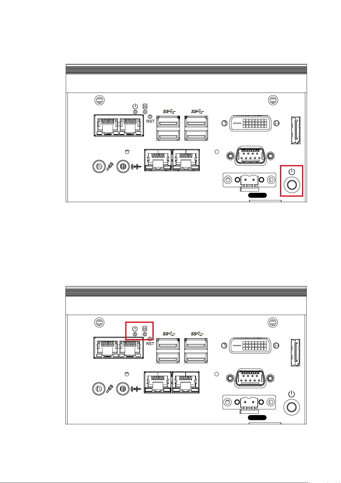
2.2.1.2 Power Button
DVI-D
On | Off
LAN 1 LAN 2
Switch
The power button is a non-latched switch. In case of system halts, you can
press and hold the power button for 4 seconds to compulsorily shut down the
system. Please note that a 4 seconds interval is kept by the system between
two on/off operations (i.e. once turning off the system, you shall wait for 4
seconds to initiate another power-on operation).
GETTING TO KNOW YOUR SPC-3000/3500©Vecow SPC-3000/3500 User Manual
DP
16
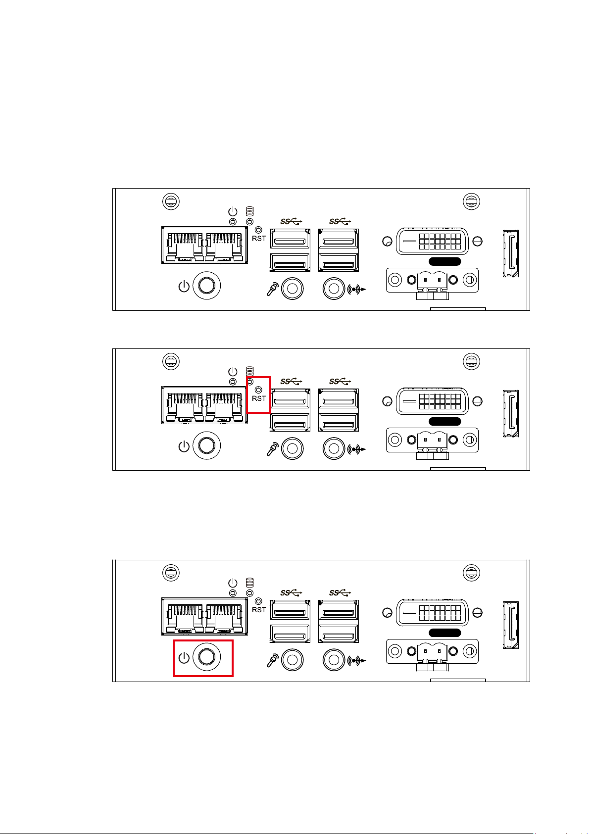
2.2.1.3 PWR and HDD LED Indicator
LAN 1 LAN 2
Switch
DVI-D
On | Off
DP
Yellow-HDD LED: A hard disk LED. If the LED is on, it indicates that the
system’s storage is functional. If it is off, it indicates that the system’s storage is
not functional. If it is ashing, it indicates data access activities are in progress.
Green-Power LED: If the LED is solid green, it indicates that the system is
powered on.
LED Color Power Status System Status
Yellow HDD
Green Power System power status (on/ off)
• On/ Off : Storage status, function or not.
• Twinkling : Data transferring.
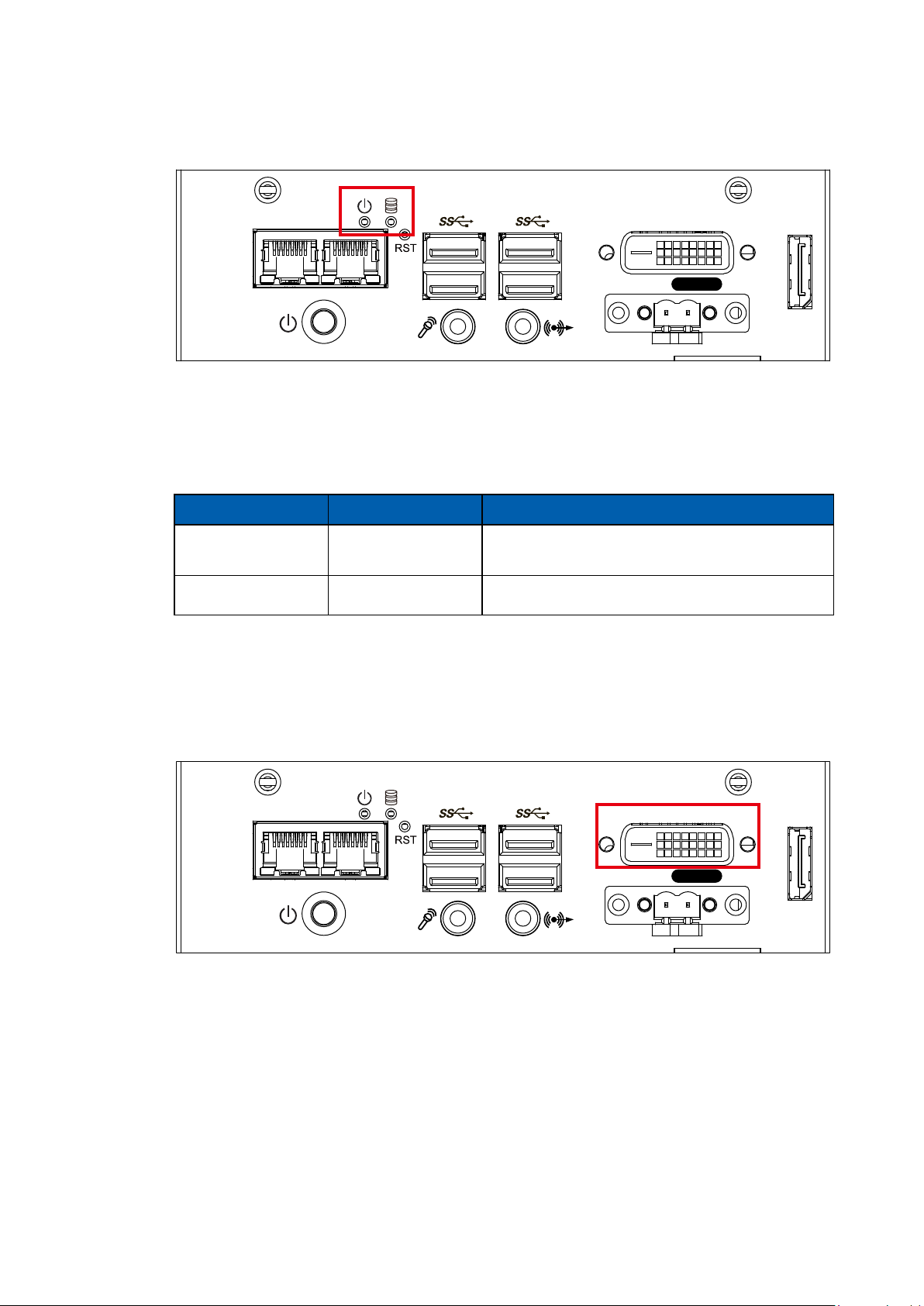
2.2.1.4 DVI-D Connector
DVI-D
On | Off
LAN 1 LAN 2
Switch
The DVI-D connector on the front panel supports both DVI display. This
connector can either output DVI signals signal. The DVI output mode supports
up to 1920 x 1200 resolution and output mode supports up to 1920 x 1200
resolution. The DVI is automatically selected according to the display device
connected. You will need a DVI-D cable when connecting to a display device.
DP
GETTING TO KNOW YOUR SPC-3000/3500
17
DVI-D
DP
LAN 1 LAN 2
Switch
On | Off
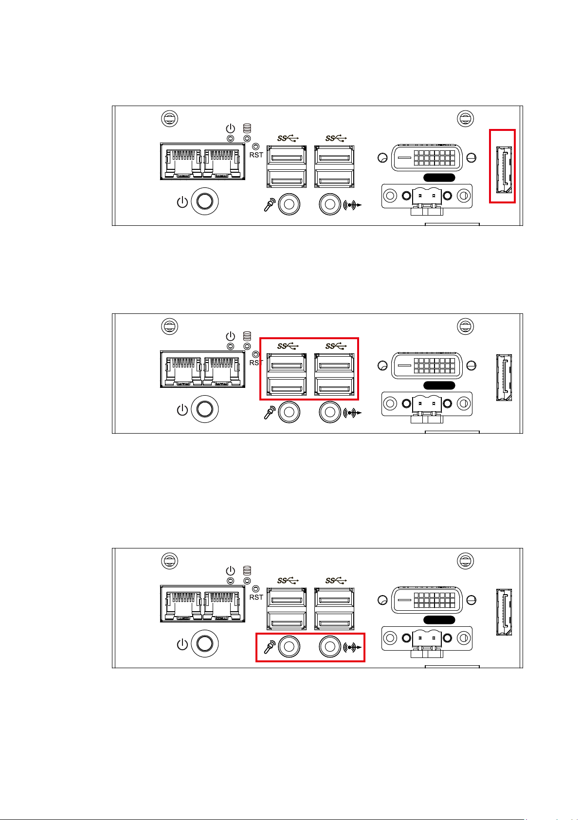
2.2.1.5 DisplayPort
DVI-D
DP
LAN 1 LAN 2
Switch
On | Off
DVI-D
DP
LAN 1 LAN 2
Switch
On | Off
Onboard DisplayPort connection supports up to 4096 x 2304 resolution at 60Hz.
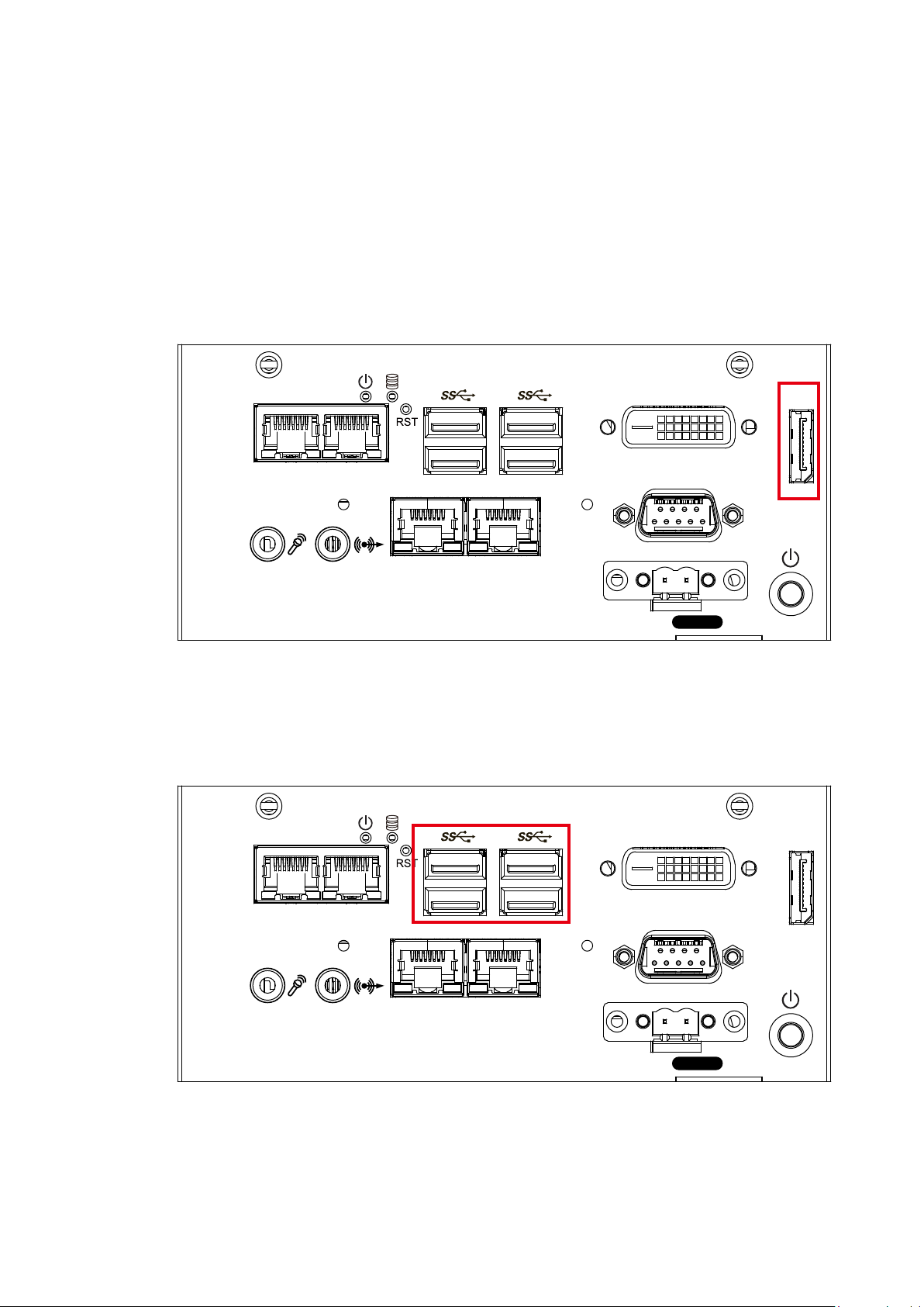
2.2.1.6 USB 3.0
There are 4 USB 3.0 connections available supporting up to 5GB per second
data rate in the front side of SPC-3010. It also compliant with the requirements
of Super Speed (SS), high speed (HS), full speed (FS) and low speed (LS).
2.2.1.7 Audio Jack
There are 2 audio connectors, Mic-in and Line-out, in the front side of SPC-
3010. Onboard Realtek ALC892 audio codec supports 5.1 channel HD audio
and fully complies with Intel® High Definition Audio (Azalia) specifications. To
utilize the audio function in Windows platform, you need to install corresponding
drivers for Realtek ALC892 codec.
GETTING TO KNOW YOUR SPC-3000/3500©Vecow SPC-3000/3500 User Manual
18
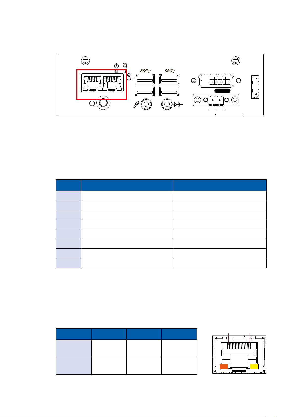
2.2.1.8 10/ 100/ 1000 Mbps Ethernet Port
1 8
LAN 1 LAN 2
Switch
DVI-D
On | Off
DP
There are 2 8-pin RJ-45 jacks supporting 10/ 100/1000 Mbps Ethernet
connections in the front side. LAN 1 is powered by Intel i219 Ethernet Phy; LAN
2 is powered by Intel I210 Ethernet engine. When both LAN 1 and LAN 2 work
in normal status, iAMT 11.0 function is enabled. Using suitable RJ-45 cable, you
can connect the system to a computer, or to any other devices with Ethernet
connection, for example, a hub or a switch. Moreover, both of LAN 1 and LAN 2
supports Wake on LAN and Pre-boot functions. The pin-outs of LAN 1 and LAN
2 are listed as follows:
Pin No. 10/ 100Mbps 1000Mbps
1 E_TX+ MDI0_P
2 E_TX- MDI0_N
3 E_RX+ MDI1_P
4 ---- MDI2_P
5 ----- MDI2_N
6 E_RX- MDI1_N
7 ----- MDI3_P
8 ------ MDI3_N
Each LAN port is supported by standard RJ-45 connector with LED indicators to
present Active/ Link/ Speed status of the connection. The LED indicator on the
right bottom corner lightens in solid green when the cable is properly connected
to a 100 Mbps Ethernet network; The LED indicator on the right bottom corner
lightens in solid orange when the cable is properly connected to a 1000Mbps
Ethernet network; The left LED will keep twinkling/ off when Ethernet data
packets are being transmitted/ received.
10Mbps 100Mbps 1000Mbps
Right
Bottom Led
Off
Solid
Green
Solid
Orange
Left
Bottom Led
Flash
Yellow
Flash
Yellow
Flash
Yellow
GETTING TO KNOW YOUR SPC-3000/3500
19
2.2.1.9 Remote Power On/ O Switch
DVI-D
COM 1
DP
LAN 1 LAN 2
Switch
On | Off
LAN 4 LAN 3
LAN 1 LAN 2
Switch
DVI-D
On | Off
DP
It is a 2-pin power-on/power-off switch through Phoenix Contact terminal block.
You could turn on or off the system power by using this contact. This terminal
block supports dual function on soft power-on/power-off (instant off or delay
four seconds), and suspend mode.
Pin No. Denition Pin No. Denition
1 SW+ 2 SW-
2.2.2 SPC-3020 Front I/O & Functions
In Vecow’s SPC-3000 series family, all I/O connectors are located on the front
panel. Most of the general connections to the computer device, such as audio,
USB, DVI-D, LAN Jack, and DisplayPort, are placed on the front panel.
GETTING TO KNOW YOUR SPC-3000/3500©Vecow SPC-3000/3500 User Manual
20
2.2.2.1 Reset Tact Switch
LAN 1 LAN 2
LAN 4 LAN 3
Switch
DVI-D
COM 1
On | Off
DP
It is a hardware reset switch. Use this switch to reset the system without power
off the system. Press the Reset Switch for a few seconds, then reset will be
enabled.
2.2.2.2 Power Button
LAN 1 LAN 2
LAN 4 LAN 3
Switch
DVI-D
COM 1
On | Off
DP
The power button is a non-latched switch. In case of system halts, you can
press and hold the power button for 4 seconds to compulsorily shut down the
system. Please note that a 4 seconds interval is kept by the system between
two on/off operations (i.e. once turning off the system, you shall wait for 4
seconds to initiate another power-on operation).
GETTING TO KNOW YOUR SPC-3000/3500
21
2.2.2.3 PWR and HDD LED Indicator
LAN 1 LAN 2
LAN 4 LAN 3
Switch
DVI-D
COM 1
On | Off
DP
Yellow-HDD LED: A hard disk LED. If the LED is on, it indicates that the
system’s storage is functional. If it is off, it indicates that the system’s storage is
not functional. If it is ashing, it indicates data access activities are in progress.
Green-Power LED: If the LED is solid green, it indicates that the system is
powered on.
LED Color Power Status System Status
Yellow HDD
• On/ Off : Storage status, function or not.
• Twinkling : Data transferring.
Green Power System power status (on/ off)
2.2.2.4 DVI-D Connector
DVI-D
LAN 1 LAN 2
LAN 4 LAN 3
Switch
COM 1
On | Off
DP
GETTING TO KNOW YOUR SPC-3000/3500©Vecow SPC-3000/3500 User Manual
22
The DVI-D connector on the front panel supports both DVI display. This
DVI-D
COM 1
DP
LAN 1 LAN 2
Switch
On | Off
LAN 4 LAN 3
DVI-D
COM 1
DP
LAN 1 LAN 2
Switch
On | Off
LAN 4 LAN 3
connector can either output DVI signals signal. The DVI output mode supports
up to 1920 x 1200 resolution and output mode supports up to 1920 x 1200
resolution. The DVI is automatically selected according to the display device
connected. You will need a DVI-D cable when connecting to a display device.
2.2.2.5 DisplayPort
Onboard DisplayPort connection supports up to 4096 x 2304 resolution at 60Hz.
2.2.2.6 USB 3.0
There are 4 USB 3.0 connections available supporting up to 5GB per second
data rate in the front side of SPC-3020. It also compliant with the requirements
of Super Speed (SS), high speed (HS), full speed (FS) and low speed (LS).
GETTING TO KNOW YOUR SPC-3000/3500
23

2.2.2.7 Audio Jack
DVI-D
COM 1
DP
LAN 1 LAN 2
Switch
On | Off
LAN 4 LAN 3
DVI-D
COM 1
DP
LAN 1 LAN 2
Switch
On | Off
LAN 4 LAN 3
There are 2 audio connectors, Mic-in and Line-out, in the front side of SPC-
3020. Onboard Realtek ALC892 audio codec supports 5.1 channel HD audio
and fully complies with Intel® High Definition Audio (Azalia) specifications. To
utilize the audio function in Windows platform, you need to install corresponding
drivers for Realtek ALC892 codec.
2.2.2.8 10/ 100/ 1000 Mbps Ethernet Port
There are 4 8-pin RJ-45 jacks supporting 10/ 100/1000 Mbps Ethernet
connections in the front side. LAN 1 is powered by Intel i219 Ethernet Phy; LAN
2 – 4 are powered by Intel I210 Ethernet engine. When all LAN ports work in
normal status, iAMT 11.0 function is enabled. Using suitable RJ-45 cable, you
can connect the system to a computer, or to any other devices with Ethernet
connection, for example, a hub or a switch. Moreover, All of LAN ports supports
Wake on LAN and Pre-boot functions. The pin-outs of LAN 1 - 4 are listed as
follows:
GETTING TO KNOW YOUR SPC-3000/3500©Vecow SPC-3000/3500 User Manual
24

Pin No. 10/ 100Mbps 1000Mbps
1 E_TX+ MDI0_P
2 E_TX- MDI0_N
3 E_RX+ MDI1_P
4 ---- MDI2_P
5 ----- MDI2_N
6 E_RX- MDI1_N
7 ----- MDI3_P
8 ------ MDI3_N
Each LAN port is supported by standard RJ-45 connector with LED indicators to
present Active/ Link/ Speed status of the connection. The LED indicator on the
right bottom corner lightens in solid green when the cable is properly connected
to a 100 Mbps Ethernet network; The LED indicator on the right bottom corner
lightens in solid orange when the cable is properly connected to a 1000Mbps
Ethernet network; The left LED will keep twinkling/ off when Ethernet data
packets are being transmitted/ received.
10Mbps 100Mbps 1000Mbps
Right
Bottom Led
Left
Bottom Led
Off
Flash
Yellow
Solid
Green
Flash
Yellow
2.2.2.9 Remote Power On/ O Switch
LAN 1 LAN 2
LAN 4 LAN 3
Solid
Orange
Flash
Yellow
DVI-D
COM 1
1 8
DP
On | Off
Switch
It is a 2-pin power-on/power-off switch through Phoenix Contact terminal block.
You could turn on or off the system power by using this contact. This terminal
block supports dual function on soft power-on/power-off (instant off or delay
four seconds), and suspend mode.
GETTING TO KNOW YOUR SPC-3000/3500
25

Pin No. Denition Pin No. Denition
DVI-D
COM 1
DP
LAN 1 LAN 2
Switch
On | Off
LAN 4 LAN 3
1 SW+ 2 SW-
2.2.2.10 Serial Port COM
Serial port can be configured for RS-232, RS-422, or RS-485 with auto flow
control communication. The default definition is RS-232, but if you want to
change to RS-422 or RS-485, you can nd the settings in BIOS.
BIOS Setting Function
RS-232
RS-422 (5-wire)
COM 1
RS-422 (9-wire)
RS-485
RS-485 w/z auto-ow control
The pin assignments are listed in the table as follow :
Serial
Port
COM 1
Pin No. RS-232 RS-422
(5-wire)
1 DCD TXD- TXD- DATA-
2 RXD TXD+ TXD+ DATA+
3 TXD RXD+ RXD+ -----------
4 DTR RXD- RXD- -----------
5 GND GND GND GND
6 DSR ----------- RTS- -----------
RS-422
(9-wire)
RS-485
(3-wire)
7 RTS ----------- RTS+ -----------
8 CTS ----------- CTS+ -----------
9 RI ----------- CTS- -----------
GETTING TO KNOW YOUR SPC-3000/3500©Vecow SPC-3000/3500 User Manual
26

2.2.3 SPC-3030 Front I/O & Functions
DVI-D
COM 1
DP
LAN 1 LAN 2
Switch
On | Off
LAN 4 LAN 3
In Vecow’s SPC-3000 series family, all I/O connectors are located on the front
panel. Most of the general connections to the computer device, such as audio,
USB, DVI-D, LAN Jack, and DisplayPort, are placed on the front panel.
2.2.3.1 Reset Tact Switch
It is a hardware reset switch. Use this switch to reset the system without power
off the system. Press the Reset Switch for a few seconds, then reset will be
enabled.
LAN 1 LAN 2
LAN 4 LAN 3
Switch
DVI-D
COM 1
On | Off
DP
GETTING TO KNOW YOUR SPC-3000/3500
27

2.2.3.2 Power Button
LAN 1 LAN 2
LAN 4 LAN 3
Switch
DVI-D
COM 1
On | Off
DP
The power button is a non-latched switch. In case of system halts, you can
press and hold the power button for 4 seconds to compulsorily shut down the
system. Please note that a 4 seconds interval is kept by the system between
two on/off operations (i.e. once turning off the system, you shall wait for 4
seconds to initiate another power-on operation).
2.2.3.3 PWR and HDD LED Indicator
LAN 1 LAN 2
LAN 4 LAN 3
Switch
DVI-D
COM 1
On | Off
DP
GETTING TO KNOW YOUR SPC-3000/3500©Vecow SPC-3000/3500 User Manual
28

Yellow-HDD LED: A hard disk LED. If the LED is on, it indicates that the
system’s storage is functional. If it is off, it indicates that the system’s storage is
not functional. If it is ashing, it indicates data access activities are in progress.
Green-Power LED: If the LED is solid green, it indicates that the system is
powered on.
LED Color Power Status System Status
Yellow HDD
• On/ Off : Storage status, function or not.
• Twinkling : Data transferring.
Green Power System power status (on/ off)
2.2.3.4 DVI-D Connector
DVI-D
LAN 1 LAN 2
LAN 4 LAN 3
COM 1
DP
On | Off
Switch
The DVI-D connector on the front panel supports both DVI display. This
connector can either output DVI signals signal. The DVI output mode supports
up to 1920 x 1200 resolution and output mode supports up to 1920 x 1200
resolution. The DVI is automatically selected according to the display device
connected. You will need a DVI-D cable when connecting to a display device.
GETTING TO KNOW YOUR SPC-3000/3500
29

DVI-D
COM 1
DP
LAN 1 LAN 2
Switch
On | Off
LAN 4 LAN 3
2.2.3.5 DisplayPort
DVI-D
COM 1
DP
LAN 1 LAN 2
Switch
On | Off
LAN 4 LAN 3
Onboard DisplayPort connection supports up to 4096 x 2304 resolution at 60Hz.
2.2.3.6 USB 3.0
There are 4 USB 3.0 connections available supporting up to 5GB per second
data rate in the front side of SPC-3030. It also compliant with the requirements
of Super Speed (SS), high speed (HS), full speed (FS) and low speed (LS).
GETTING TO KNOW YOUR SPC-3000/3500©Vecow SPC-3000/3500 User Manual
30

2.2.3.7 Audio Jack
DVI-D
COM 1
DP
LAN 1 LAN 2
Switch
On | Off
LAN 4 LAN 3
DVI-D
COM 1
DP
LAN 1 LAN 2
Switch
On | Off
LAN 4 LAN 3
There are 2 audio connectors, Mic-in and Line-out, in the front side of SPC-
3030. Onboard Realtek ALC892 audio codec supports 5.1 channel HD audio
and fully complies with Intel® High Definition Audio (Azalia) specifications. To
utilize the audio function in Windows platform, you need to install corresponding
drivers for Realtek ALC892 codec.
2.2.3.8 10/ 100/ 1000 Mbps Ethernet Port
GETTING TO KNOW YOUR SPC-3000/3500
31

There are 4 8-pin RJ-45 jacks supporting 10/ 100/1000 Mbps Ethernet
connections in the front side. LAN 1 is powered by Intel i219 Ethernet Phy; LAN
2 – 4 are powered by Intel I210 Ethernet engine. When all LAN ports work in
normal status, iAMT 11.0 function is enabled. Using suitable RJ-45 cable, you
can connect the system to a computer, or to any other devices with Ethernet
connection, for example, a hub or a switch. Moreover, All of LAN ports supports
Wake on LAN and Pre-boot functions. The pin-outs of LAN 1 - 4 are listed as
follows:
Pin No. 10/ 100Mbps 1000Mbps
1 E_TX+ MDI0_P
2 E_TX- MDI0_N
3 E_RX+ MDI1_P
4 ---- MDI2_P
5 ----- MDI2_N
6 E_RX- MDI1_N
7 ----- MDI3_P
8 ------ MDI3_N
Each LAN port is supported by standard RJ-45 connector with LED indicators to
present Active/ Link/ Speed status of the connection. The LED indicator on the
right bottom corner lightens in solid green when the cable is properly connected
to a 100 Mbps Ethernet network; The LED indicator on the right bottom corner
lightens in solid orange when the cable is properly connected to a 1000Mbps
Ethernet network; The left LED will keep twinkling/ off when Ethernet data
packets are being transmitted/ received.
1 8
Right
Bottom Led
Left
Bottom Led
10Mbps 100Mbps 1000Mbps
Off
Flash
Yellow
Solid
Green
Flash
Yellow
Solid
Orange
Flash
Yellow
GETTING TO KNOW YOUR SPC-3000/3500©Vecow SPC-3000/3500 User Manual
32

2.2.3.9 Remote Power On/ O Switch
DVI-D
COM 1
DP
LAN 1 LAN 2
Switch
On | Off
LAN 4 LAN 3
LAN 1 LAN 2
LAN 4 LAN 3
Switch
DVI-D
COM 1
On | Off
DP
It is a 2-pin power-on/power-off switch through Phoenix Contact terminal block.
You could turn on or off the system power by using this contact. This terminal
block supports dual function on soft power-on/power-off (instant off or delay
four seconds), and suspend mode.
Pin No. Denition Pin No. Denition
2.2.3.10 Serial Port COM
1 SW+ 2 SW-
GETTING TO KNOW YOUR SPC-3000/3500
33

Serial port can be configured for RS-232, RS-422, or RS-485 with auto flow
control communication. The default definition is RS-232, but if you want to
change to RS-422 or RS-485, you can nd the settings in BIOS.
BIOS Setting Function
RS-232
RS-422 (5-wire)
COM 1
RS-422 (9-wire)
RS-485
RS-485 w/z auto-ow control
The pin assignments are listed in the table as follow :
Serial
Port
COM 1
Pin No. RS-232 RS-422
(5-wire)
1 DCD TXD- TXD- DATA-
2 RXD TXD+ TXD+ DATA+
3 TXD RXD+ RXD+ -----------
4 DTR RXD- RXD- -----------
5 GND GND GND GND
6 DSR ----------- RTS- -----------
7 RTS ----------- RTS+ -----------
8 CTS ----------- CTS+ -----------
9 RI ----------- CTS- -----------
RS-422
(9-wire)
RS-485
(3-wire)
2.2.4 SPC-3510 Front I/O & Functions
In Vecow’s SPC-3500 series family, all I/O connectors are located on the front
panel. Most of the general connections to the computer device, such as audio,
USB, DVI-D, LAN Jack, and DisplayPort, are placed on the front panel.
LAN 1 LAN 2
DVI-D
On | Off
Switch
GETTING TO KNOW YOUR SPC-3000/3500©Vecow SPC-3000/3500 User Manual
DP
34

2.2.4.1 Reset Tact Switch
LAN 1 LAN 2
Switch
DVI-D
On | Off
DP
It is a hardware reset switch. Use this switch to reset the system without power
off the system. Press the Reset Switch for a few seconds, then reset will be
enabled.
2.2.4.2 Power Button
LAN 1 LAN 2
Switch
DVI-D
On | Off
DP
The power button is a non-latched switch. In case of system halts, you can
press and hold the power button for 4 seconds to compulsorily shut down the
system. Please note that a 4 seconds interval is kept by the system between
two on/off operations (i.e. once turning off the system, you shall wait for 4
seconds to initiate another power-on operation).
GETTING TO KNOW YOUR SPC-3000/3500
35

2.2.4.3 PWR and HDD LED Indicator
LAN 1 LAN 2
Switch
DVI-D
On | Off
DP
Yellow-HDD LED: A hard disk LED. If the LED is on, it indicates that the
system’s storage is functional. If it is off, it indicates that the system’s storage is
not functional. If it is ashing, it indicates data access activities are in progress.
Green-Power LED: If the LED is solid green, it indicates that the system is
powered on.
LED Color Power Status System Status
Yellow HDD
Green Power System power status (on/ off)
• On/ Off : Storage status, function or not.
• Twinkling : Data transferring.
2.2.4.4 DVI-D Connector
DVI-D
On | Off
LAN 1 LAN 2
Switch
The DVI-D connector on the front panel supports both DVI display. This
connector can either output DVI signals signal. The DVI output mode supports
up to 1920 x 1200 resolution and output mode supports up to 1920 x 1200
resolution. The DVI is automatically selected according to the display device
connected. You will need a DVI-D cable when connecting to a display device.
DP
GETTING TO KNOW YOUR SPC-3000/3500©Vecow SPC-3000/3500 User Manual
36

DVI-D
DP
LAN 1 LAN 2
Switch
On | Off
2.2.4.5 DisplayPort
DVI-D
DP
LAN 1 LAN 2
Switch
On | Off
DVI-D
DP
LAN 1 LAN 2
Switch
On | Off
Onboard DisplayPort connection supports up to 4096 x 2304 resolution at 60Hz.
2.2.4.6 USB 3.0
There are 4 USB 3.0 connections available supporting up to 5GB per second
data rate in the front side of SPC-3510. It also compliant with the requirements
of Super Speed (SS), high speed (HS), full speed (FS) and low speed (LS).
2.2.4.7 Audio Jack
GETTING TO KNOW YOUR SPC-3000/3500
37

There are 2 audio connectors, Mic-in and Line-out, in the front side of SPC-
3510. Onboard Realtek ALC892 audio codec supports 5.1 channel HD audio
and fully complies with Intel® High Definition Audio (Azalia) specifications. To
utilize the audio function in Windows platform, you need to install corresponding
drivers for Realtek ALC892 codec.
2.2.4.8 10/ 100/ 1000 Mbps Ethernet Port
LAN 1 LAN 2
Switch
DVI-D
On | Off
DP
There are 2 8-pin RJ-45 jacks supporting 10/ 100/1000 Mbps Ethernet
connections in the front side. LAN 1 is powered by Intel i219 Ethernet Phy; LAN
2 is powered by Intel I210 Ethernet engine. When both LAN 1 and LAN 2 work
in normal status, iAMT 11.0 function is enabled. Using suitable RJ-45 cable, you
can connect the system to a computer, or to any other devices with Ethernet
connection, for example, a hub or a switch. Moreover, both of LAN 1 and LAN 2
supports Wake on LAN and Pre-boot functions. The pin-outs of LAN 1 and LAN
2 are listed as follows:
Pin No. 10/ 100Mbps 1000Mbps
1 E_TX+ MDI0_P
2 E_TX- MDI0_N
3 E_RX+ MDI1_P
4 ---- MDI2_P
5 ----- MDI2_N
6 E_RX- MDI1_N
7 ----- MDI3_P
8 ------ MDI3_N
GETTING TO KNOW YOUR SPC-3000/3500©Vecow SPC-3000/3500 User Manual
38

Each LAN port is supported by standard RJ-45 connector with LED indicators to
1 8
present Active/ Link/ Speed status of the connection. The LED indicator on the
right bottom corner lightens in solid green when the cable is properly connected
to a 100 Mbps Ethernet network; The LED indicator on the right bottom corner
lightens in solid orange when the cable is properly connected to a 1000Mbps
Ethernet network; The left LED will keep twinkling/ off when Ethernet data
packets are being transmitted/ received.
10Mbps 100Mbps 1000Mbps
Right
Bottom Led
Left
Bottom Led
Off
Flash
Yellow
Solid
Green
Flash
Yellow
2.2.4.9 Remote Power On/ O Switch
Solid
Orange
Flash
Yellow
DVI-D
DP
On | Off
LAN 1 LAN 2
Switch
It is a 2-pin power-on/power-off switch through Phoenix Contact terminal block.
You could turn on or off the system power by using this contact. This terminal
block supports dual function on soft power-on/power-off (instant off or delay
four seconds), and suspend mode.
Pin No. Denition Pin No. Denition
1 SW+ 2 SW-
GETTING TO KNOW YOUR SPC-3000/3500
39

2.2.5 SPC-3520 Front I/O & Functions
DVI-D
COM 1
DP
LAN 1 LAN 2
Switch
On | Off
LAN 4 LAN 3
In Vecow’s SPC-3500 series family, all I/O connectors are located on the front
panel. Most of the general connections to the computer device, such as audio,
USB, DVI-D, LAN Jack, and DisplayPort, are placed on the front panel.
2.2.5.1 Reset Tact Switch
It is a hardware reset switch. Use this switch to reset the system without power
off the system. Press the Reset Switch for a few seconds, then reset will be
enabled.
LAN 1 LAN 2
LAN 4 LAN 3
Switch
DVI-D
COM 1
On | Off
DP
GETTING TO KNOW YOUR SPC-3000/3500©Vecow SPC-3000/3500 User Manual
40
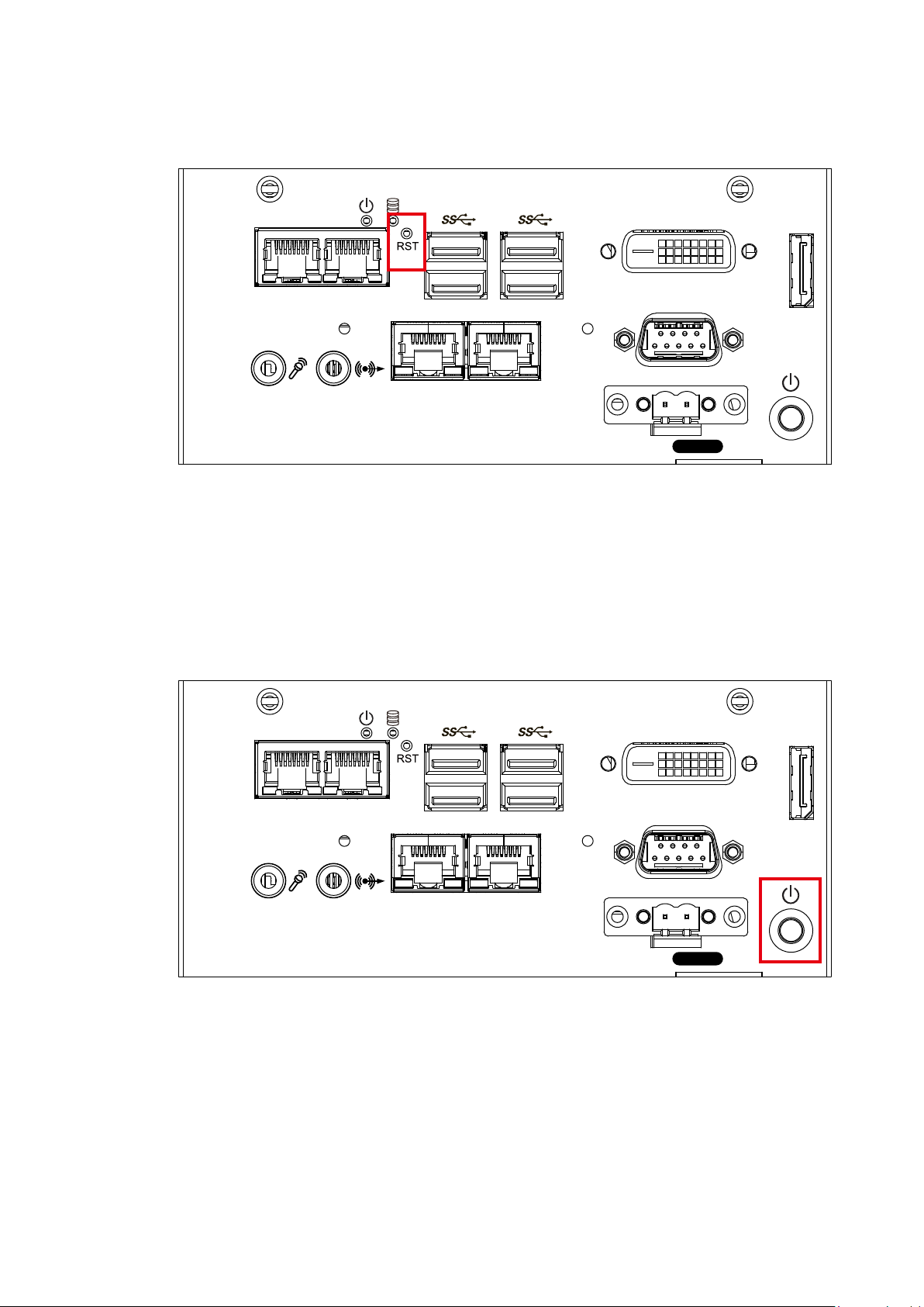
2.2.5.2 Power Button
LAN 1 LAN 2
LAN 4 LAN 3
Switch
DVI-D
COM 1
On | Off
DP
The power button is a non-latched switch. In case of system halts, you can
press and hold the power button for 4 seconds to compulsorily shut down the
system. Please note that a 4 seconds interval is kept by the system between
two on/off operations (i.e. once turning off the system, you shall wait for 4
seconds to initiate another power-on operation).
2.2.5.3 PWR and HDD LED Indicator
LAN 1 LAN 2
LAN 4 LAN 3
GETTING TO KNOW YOUR SPC-3000/3500
Switch
DVI-D
COM 1
On | Off
DP
41

Yellow-HDD LED: A hard disk LED. If the LED is on, it indicates that the
system’s storage is functional. If it is off, it indicates that the system’s storage is
not functional. If it is ashing, it indicates data access activities are in progress.
Green-Power LED: If the LED is solid green, it indicates that the system is
powered on.
LED Color Power Status System Status
Yellow HDD
• On/ Off : Storage status, function or not.
• Twinkling : Data transferring.
Green Power System power status (on/ off)
2.2.5.4 DVI-D Connector
DVI-D
LAN 1 LAN 2
COM 1
DP
LAN 4 LAN 3
On | Off
Switch
The DVI-D connector on the front panel supports both DVI display. This
connector can either output DVI signals signal. The DVI output mode supports
up to 1920 x 1200 resolution and output mode supports up to 1920 x 1200
resolution. The DVI is automatically selected according to the display device
connected. You will need a DVI-D cable when connecting to a display device.
GETTING TO KNOW YOUR SPC-3000/3500©Vecow SPC-3000/3500 User Manual
42

DVI-D
COM 1
DP
LAN 1 LAN 2
Switch
On | Off
LAN 4 LAN 3
2.2.5.5 DisplayPort
DVI-D
COM 1
DP
LAN 1 LAN 2
Switch
On | Off
LAN 4 LAN 3
Onboard DisplayPort connection supports up to 4096 x 2304 resolution at 60Hz.
2.2.5.6 USB 3.0
There are 4 USB 3.0 connections available supporting up to 5GB per second
data rate in the front side of SPC-3520. It also compliant with the requirements
of Super Speed (SS), high speed (HS), full speed (FS) and low speed (LS).
GETTING TO KNOW YOUR SPC-3000/3500
43

2.2.5.7 Audio Jack
DVI-D
COM 1
DP
LAN 1 LAN 2
Switch
On | Off
LAN 4 LAN 3
DVI-D
COM 1
DP
LAN 1 LAN 2
Switch
On | Off
LAN 4 LAN 3
There are 2 audio connectors, Mic-in and Line-out, in the front side of SPC-
3520. Onboard Realtek ALC892 audio codec supports 5.1 channel HD audio
and fully complies with Intel® High Definition Audio (Azalia) specifications. To
utilize the audio function in Windows platform, you need to install corresponding
drivers for Realtek ALC892 codec.
2.2.5.8 10/ 100/ 1000 Mbps Ethernet Port
GETTING TO KNOW YOUR SPC-3000/3500©Vecow SPC-3000/3500 User Manual
44

There are 4 8-pin RJ-45 jacks supporting 10/ 100/1000 Mbps Ethernet
connections in the front side. LAN 1 is powered by Intel i219 Ethernet Phy; LAN
2 – 4 are powered by Intel I210 Ethernet engine. When all LAN ports work in
normal status, iAMT 11.0 function is enabled. Using suitable RJ-45 cable, you
can connect the system to a computer, or to any other devices with Ethernet
connection, for example, a hub or a switch. Moreover, All of LAN ports supports
Wake on LAN and Pre-boot functions. The pin-outs of LAN 1 - 4 are listed as
follows:
Pin No. 10/ 100Mbps 1000Mbps
1 E_TX+ MDI0_P
2 E_TX- MDI0_N
3 E_RX+ MDI1_P
4 ---- MDI2_P
5 ----- MDI2_N
6 E_RX- MDI1_N
7 ----- MDI3_P
8 ------ MDI3_N
Each LAN port is supported by standard RJ-45 connector with LED indicators to
present Active/ Link/ Speed status of the connection. The LED indicator on the
right bottom corner lightens in solid green when the cable is properly connected
to a 100 Mbps Ethernet network; The LED indicator on the right bottom corner
lightens in solid orange when the cable is properly connected to a 1000Mbps
Ethernet network; The left LED will keep twinkling/ off when Ethernet data
packets are being transmitted/ received.
1 8
Right
Bottom Led
Left
Bottom Led
10Mbps 100Mbps 1000Mbps
Off
Flash
Yellow
Solid
Green
Flash
Yellow
Solid
Orange
Flash
Yellow
GETTING TO KNOW YOUR SPC-3000/3500
45

2.2.5.9 Remote Power On/ O Switch
DVI-D
COM 1
DP
LAN 1 LAN 2
Switch
On | Off
LAN 4 LAN 3
LAN 1 LAN 2
LAN 4 LAN 3
Switch
DVI-D
COM 1
On | Off
DP
It is a 2-pin power-on/power-off switch through Phoenix Contact terminal block.
You could turn on or off the system power by using this contact. This terminal
block supports dual function on soft power-on/power-off (instant off or delay
four seconds), and suspend mode.
Pin No. Denition Pin No. Denition
1 SW+ 2 SW-
2.2.5.10 Serial Port COM
GETTING TO KNOW YOUR SPC-3000/3500©Vecow SPC-3000/3500 User Manual
46

Serial port can be configured for RS-232, RS-422, or RS-485 with auto flow
control communication. The default definition is RS-232, but if you want to
change to RS-422 or RS-485, you can nd the settings in BIOS.
BIOS Setting Function
RS-232
RS-422 (5-wire)
COM 1
RS-422 (9-wire)
RS-485
RS-485 w/z auto-ow control
The pin assignments are listed in the table as follow :
Serial
Port
COM 1
Pin No. RS-232 RS-422
(5-wire)
1 DCD TXD- TXD- DATA-
2 RXD TXD+ TXD+ DATA+
3 TXD RXD+ RXD+ -----------
4 DTR RXD- RXD- -----------
5 GND GND GND GND
6 DSR ----------- RTS- -----------
7 RTS ----------- RTS+ -----------
8 CTS ----------- CTS+ -----------
9 RI ----------- CTS- -----------
RS-422
(9-wire)
RS-485
(3-wire)
2.2.6 SPC-3530 Front I/O & Functions
In Vecow’s SPC-3500 series family, all I/O connectors are located on the front
panel. Most of the general connections to the computer device, such as audio,
USB, DVI-D, LAN Jack, and DisplayPort, are placed on the front panel.
GETTING TO KNOW YOUR SPC-3000/3500
47

DVI-D
COM 1
DP
LAN 1 LAN 2
Switch
On | Off
LAN 4 LAN 3
2.2.6.1 Reset Tact Switch
It is a hardware reset switch. Use this switch to reset the system without power
off the system. Press the Reset Switch for a few seconds, then reset will be
enabled.
LAN 1 LAN 2
LAN 4 LAN 3
Switch
DVI-D
COM 1
On | Off
DP
GETTING TO KNOW YOUR SPC-3000/3500©Vecow SPC-3000/3500 User Manual
48

2.2.6.2 Power Button
LAN 1 LAN 2
LAN 4 LAN 3
Switch
DVI-D
COM 1
On | Off
DP
The power button is a non-latched switch. In case of system halts, you can
press and hold the power button for 4 seconds to compulsorily shut down the
system. Please note that a 4 seconds interval is kept by the system between
two on/off operations (i.e. once turning off the system, you shall wait for 4
seconds to initiate another power-on operation).
2.2.6.3 PWR and HDD LED Indicator
LAN 1 LAN 2
LAN 4 LAN 3
Switch
DVI-D
COM 1
On | Off
DP
GETTING TO KNOW YOUR SPC-3000/3500
49

Yellow-HDD LED: A hard disk LED. If the LED is on, it indicates that the
system’s storage is functional. If it is off, it indicates that the system’s storage is
not functional. If it is ashing, it indicates data access activities are in progress.
Green-Power LED: If the LED is solid green, it indicates that the system is
powered on.
LED Color Power Status System Status
Yellow HDD
• On/ Off : Storage status, function or not.
• Twinkling : Data transferring.
Green Power System power status (on/ off)
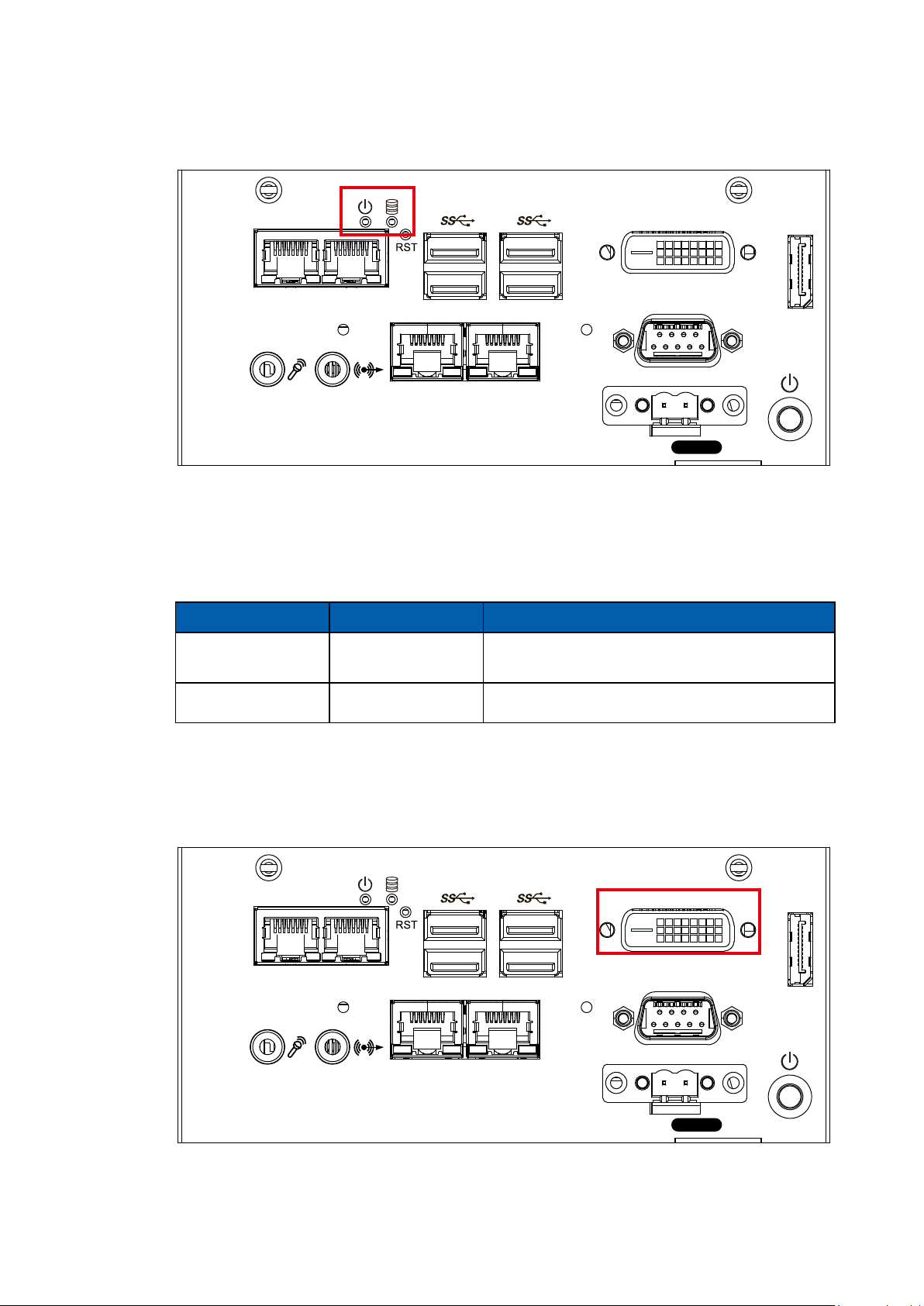
2.2.6.4 DVI-D Connector
DVI-D
LAN 1 LAN 2
COM 1
DP
LAN 4 LAN 3
On | Off
Switch
The DVI-D connector on the front panel supports both DVI display. This
connector can either output DVI signals signal. The DVI output mode supports
up to 1920 x 1200 resolution and output mode supports up to 1920 x 1200
resolution. The DVI is automatically selected according to the display device
connected. You will need a DVI-D cable when connecting to a display device.
GETTING TO KNOW YOUR SPC-3000/3500©Vecow SPC-3000/3500 User Manual
50

DVI-D
COM 1
DP
LAN 1 LAN 2
Switch
On | Off
LAN 4 LAN 3
2.2.6.5 DisplayPort
DVI-D
COM 1
DP
LAN 1 LAN 2
Switch
On | Off
LAN 4 LAN 3
Onboard DisplayPort connection supports up to 4096 x 2304 resolution at 60Hz.
2.2.6.6 USB 3.0
There are 4 USB 3.0 connections available supporting up to 5GB per second
data rate in the front side of SPC-3530. It also compliant with the requirements
of Super Speed (SS), high speed (HS), full speed (FS) and low speed (LS).
GETTING TO KNOW YOUR SPC-3000/3500
51

2.2.6.7 Audio Jack
DVI-D
COM 1
DP
LAN 1 LAN 2
Switch
On | Off
LAN 4 LAN 3
DVI-D
COM 1
DP
LAN 1 LAN 2
Switch
On | Off
LAN 4 LAN 3
There are 2 audio connectors, Mic-in and Line-out, in the front side of SPC-
3530. Onboard Realtek ALC892 audio codec supports 5.1 channel HD audio
and fully complies with Intel® High Definition Audio (Azalia) specifications. To
utilize the audio function in Windows platform, you need to install corresponding
drivers for Realtek ALC892 codec.
2.2.6.8 10/ 100/ 1000 Mbps Ethernet Port
GETTING TO KNOW YOUR SPC-3000/3500©Vecow SPC-3000/3500 User Manual
52

There are 4 8-pin RJ-45 jacks supporting 10/ 100/1000 Mbps Ethernet
connections in the front side. LAN 1 is powered by Intel i219 Ethernet Phy; LAN
2 – 4 are powered by Intel I210 Ethernet engine. When all LAN ports work in
normal status, iAMT 11.0 function is enabled. Using suitable RJ-45 cable, you
can connect the system to a computer, or to any other devices with Ethernet
connection, for example, a hub or a switch. Moreover, All of LAN ports supports
Wake on LAN and Pre-boot functions. The pin-outs of LAN 1 - 4 are listed as
follows:
Pin No. 10/ 100Mbps 1000Mbps
1 E_TX+ MDI0_P
2 E_TX- MDI0_N
3 E_RX+ MDI1_P
4 ---- MDI2_P
5 ----- MDI2_N
6 E_RX- MDI1_N
7 ----- MDI3_P
8 ------ MDI3_N
Each LAN port is supported by standard RJ-45 connector with LED indicators to
present Active/ Link/ Speed status of the connection. The LED indicator on the
right bottom corner lightens in solid green when the cable is properly connected
to a 100 Mbps Ethernet network; The LED indicator on the right bottom corner
lightens in solid orange when the cable is properly connected to a 1000Mbps
Ethernet network; The left LED will keep twinkling/ off when Ethernet data
packets are being transmitted/ received.
1 8
Right
Bottom Led
Left
Bottom Led
10Mbps 100Mbps 1000Mbps
Off
Flash
Yellow
Solid
Green
Flash
Yellow
Solid
Orange
Flash
Yellow
GETTING TO KNOW YOUR SPC-3000/3500
53

2.2.6.9 Remote Power On/ O Switch
LAN 1 LAN 2
LAN 4 LAN 3
Switch
DVI-D
COM 1
On | Off
DP
It is a 2-pin power-on/power-off switch through Phoenix Contact terminal block.
You could turn on or off the system power by using this contact. This terminal
block supports dual function on soft power-on/power-off (instant off or delay
four seconds), and suspend mode.
Pin No. Denition Pin No. Denition
1 SW+ 2 SW-
GETTING TO KNOW YOUR SPC-3000/3500©Vecow SPC-3000/3500 User Manual
54

2.2.6.10 Serial Port COM
DVI-D
COM 1
DP
LAN 1 LAN 2
Switch
On | Off
LAN 4 LAN 3
Serial port can be configured for RS-232, RS-422, or RS-485 with auto flow
control communication. The default definition is RS-232, but if you want to
change to RS-422 or RS-485, you can nd the settings in BIOS.
The pin assignments are listed in the table as follow :
BIOS Setting Function
RS-232
RS-422 (5-wire)
COM 1
RS-422 (9-wire)
RS-485
RS-485 w/z auto-ow control
Serial
Pin No. RS-232 RS-422
Port
1 DCD TXD- TXD- DATA-
2 RXD TXD+ TXD+ DATA+
3 TXD RXD+ RXD+ -----------
4 DTR RXD- RXD- -----------
COM 1
5 GND GND GND GND
6 DSR ----------- RTS- -----------
(5-wire)
RS-422
(9-wire)
RS-485
(3-wire)
7 RTS ----------- RTS+ -----------
8 CTS ----------- CTS+ -----------
9 RI ----------- CTS- -----------
GETTING TO KNOW YOUR SPC-3000/3500
55

2.3 Rear Panel I/O Functions
2.3.1 SPC-3010 Rear I/O & Functions
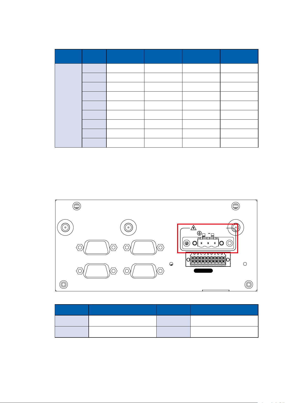
2.3.1.1 Power Terminal Block
DC-IN 9V-36V
V+ V
COM 2 COM 3
SPC-3010 supports 9V to 36V DC power input.
Pin No. Denition Pin No. Denition
1 V+ 2 V-
3 Earth GND
2.3.1.2 Serial Port COM
DC-IN 9V-36V
COM 2 COM 3
V+ V
Serial port can be configured for RS-232, RS-422, or RS-485 with auto flow
control communication. The default definition is RS-232, but if you want to
change to RS-422 or RS-485, you can nd the settings in BIOS.
BIOS Setting Function
RS-232
COM 2
COM 3
RS-422 (5-wire)
RS-422 (9-wire)
RS-485
RS-485 w/z auto-ow control
GETTING TO KNOW YOUR SPC-3000/3500©Vecow SPC-3000/3500 User Manual
56
The pin assignments are listed in the table as follow :
Serial
Port
Pin No. RS-232 RS-422
(5-wire)
1 DCD TXD- TXD- DATA-
2 RXD TXD+ TXD+ DATA+
3 TXD RXD+ RXD+ -----------
4 DTR RXD- RXD- -----------
COM 2
5 GND GND GND GND
COM 3
6 DSR ----------- RTS- -----------
7 RTS ----------- RTS+ -----------
8 CTS ----------- CTS+ -----------
9 RI ----------- CTS- -----------
2.3.2 SPC-3020 Rear I/O & Functions
RS-422
(9-wire)
RS-485
(3-wire)
2.3.2.1 Power Terminal Block
DC-IN 9V-36V
COM 2 COM 3
COM 4 COM 5
Isolated
SPC-3020 supports 9V to 36V DC power input.
Pin No. Denition Pin No. Denition
1 V+ 2 V-
V+V
DIO
3 Earth GND
GETTING TO KNOW YOUR SPC-3000/3500
57

2.3.2.2 Serial Port COM
COM 2 COM 3
COM 4 COM 5
DC-IN 9V-36V
V+V
Isolated
DIO
Serial port can be configured for RS-232, RS-422, or RS-485 with auto flow
control communication. The default definition is RS-232, but if you want to
change to RS-422 or RS-485, you can nd the settings in BIOS.
BIOS Setting Function
RS-232
COM 2
COM 3
COM 4
COM 5
RS-422 (5-wire)
RS-422 (9-wire)
RS-485
RS-485 w/z auto-ow control
The pin assignments are listed in the table as follow :
Serial
Port
Pin No. RS-232 RS-422
(5-wire)
RS-422
(9-wire)
1 DCD TXD- TXD- DATA-
RS-485
(3-wire)
COM 2
COM 3
COM 4
COM 5
2 RXD TXD+ TXD+ DATA+
3 TXD RXD+ RXD+ -----------
4 DTR RXD- RXD- -----------
5 GND GND GND GND
6 DSR ----------- RTS- -----------
7 RTS ----------- RTS+ -----------
8 CTS ----------- CTS+ -----------
9 RI ----------- CTS- -----------
GETTING TO KNOW YOUR SPC-3000/3500©Vecow SPC-3000/3500 User Manual
58

2.3.2.3 Isolated DIO
COM 2 COM 3
COM 4 COM 5
DC-IN 9V-36V
V+V
Isolated
DIO
There is a 16-bit DIO (8-bit DI, 8-bit DO) connector in the rear side. Each DIO
channel is equipped with a photocoupler for isolated protection. A power buffer
device, TPD2007F, is integrated in 8-DO circuit for motors, solenoids, and lamp
driver applications.
Pin
No.
1 INPUT 0
2 INPUT 1
3 INPUT 2
4 INPUT 3
5 INPUT 4
Denition
13 OUTPUT 2
6 INPUT 5
7 INPUT 6
8 INPUT 7
9 DI_COM
10 DIO_GND
11 OUTPUT 0
12 OUTPUT 1
14 OUTPUT 3
15 OUTPUT 4
16 OUTPUT 5
17 OUTPUT 6
18 OUTPUT 7
19 DIO_GND
20 External 6V to 36V DC Input
GETTING TO KNOW YOUR SPC-3000/3500
59

GPI SINK Mode
Isolated GPI input circuit in SINK mode (NPN) is illustrated as follow :
GPI SOURCE Mode
Digital GPI input signal circuit in SOURCE mode (PNP) is illustrated as follow :
GPO SINK Mode
Digital GPO output circuit in SINK mode (NPN) is illustrated as follow :
GETTING TO KNOW YOUR SPC-3000/3500©Vecow SPC-3000/3500 User Manual
60

2.3.3 SPC-3030 Rear I/O & Functions
2.3.3.1 Power Terminal Block
COM 6 COM 7
COM 8 COM 9
DC-IN 9V-36V
V+V
Isolated
COM 2 COM 3
COM 4 COM 5
SPC-3030 supports 9V to 36V DC power input.
Pin No. Denition Pin No. Denition
1 V+ 2 V-
3 Earth GND
2.3.3.2 Serial Port COM
DIO
COM 6 COM 7
COM 8 COM 9
COM 2 COM 3
DC-IN 9V-36V
V+V
Isolated
COM 4 COM 5
DIO
GETTING TO KNOW YOUR SPC-3000/3500
61

Serial port can be configured for RS-232, RS-422, or RS-485 with auto flow
control communication. The default definition is RS-232, but if you want to
change to RS-422 or RS-485, you can nd the settings in BIOS.
BIOS Setting Function
RS-232
COM 2, COM 3,
COM 4, COM 5,
COM 6, COM 7,
COM 8, COM 9
RS-422 (5-wire)
RS-422 (9-wire)
RS-485
RS-485 w/z auto-ow control
The pin assignments are listed in the table as follow :
Serial
Port
COM
2 to 9
Pin No. RS-232 RS-422
(5-wire)
1 DCD TXD- TXD- DATA-
2 RXD TXD+ TXD+ DATA+
3 TXD RXD+ RXD+ -----------
4 DTR RXD- RXD- -----------
5 GND GND GND GND
6 DSR ----------- RTS- -----------
7 RTS ----------- RTS+ -----------
8 CTS ----------- CTS+ -----------
RS-422
(9-wire)
RS-485
(3-wire)
9 RI ----------- CTS- -----------
GETTING TO KNOW YOUR SPC-3000/3500©Vecow SPC-3000/3500 User Manual
62

2.3.3.3 Isolated DIO
COM 6 COM 7
COM 8 COM 9
DC-IN 9V-36V
V+V
Isolated
COM 2 COM 3
COM 4 COM 5
DIO
There is a 16-bit DIO (8-bit DI, 8-bit DO) connector in the rear side. Each DIO
channel is equipped with a photocoupler for isolated protection. A power buffer
device, TPD2007F, is integrated in 8-DO circuit for motors, solenoids, and lamp
driver applications.
Pin
No.
1 INPUT 0
2 INPUT 1
3 INPUT 2
4 INPUT 3
Denition
5 INPUT 4
6 INPUT 5
7 INPUT 6
8 INPUT 7
9 DI_COM
10 DIO_GND
11 OUTPUT 0
12 OUTPUT 1
13 OUTPUT 2
14 OUTPUT 3
15 OUTPUT 4
16 OUTPUT 5
17 OUTPUT 6
18 OUTPUT 7
19 DIO_GND
20 External 6V to 36V DC Input
GETTING TO KNOW YOUR SPC-3000/3500
63

GPI SINK Mode
Isolated GPI input circuit in SINK mode (NPN) is illustrated as follow :
GPI SOURCE Mode
Digital GPI input signal circuit in SOURCE mode (PNP) is illustrated as follow :
GPO SINK Mode
Digital GPO output circuit in SINK mode (NPN) is illustrated as follow :
GETTING TO KNOW YOUR SPC-3000/3500©Vecow SPC-3000/3500 User Manual
64

2.3.4 SPC-3510 Rear I/O & Functions
2.3.4.1 Power Terminal Block
DC-IN 9V-36V
V+ V
COM 2 COM 3
SPC-3510 supports 9V to 36V DC power input.
Pin No. Denition Pin No. Denition
1 V+ 2 V-
3 Earth GND
2.3.4.2 Serial Port COM
DC-IN 9V-36V
V+ V
COM 2 COM 3
Serial port can be configured for RS-232, RS-422, or RS-485 with auto flow
control communication. The default definition is RS-232, but if you want to
change to RS-422 or RS-485, you can nd the settings in BIOS.
BIOS Setting Function
RS-232
COM 2
COM 3
RS-422 (5-wire)
RS-422 (9-wire)
RS-485
RS-485 w/z auto-ow control
GETTING TO KNOW YOUR SPC-3000/3500
65

The pin assignments are listed in the table as follow :
Serial
Port
Pin No. RS-232 RS-422
(5-wire)
1 DCD TXD- TXD- DATA-
2 RXD TXD+ TXD+ DATA+
3 TXD RXD+ RXD+ -----------
4 DTR RXD- RXD- -----------
COM 2
5 GND GND GND GND
COM 3
6 DSR ----------- RTS- -----------
7 RTS ----------- RTS+ -----------
8 CTS ----------- CTS+ -----------
9 RI ----------- CTS- -----------
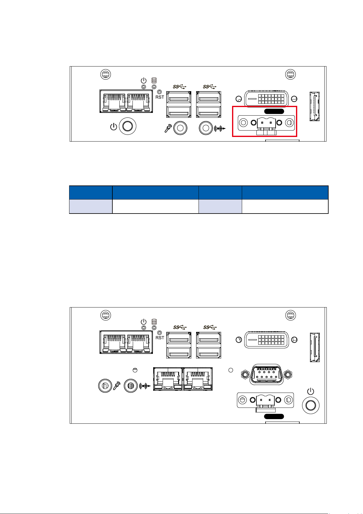
2.3.5 SPC-3520 Rear I/O & Functions
2.3.5.1 Power Terminal Block
RS-422
(9-wire)
RS-485
(3-wire)
DC-IN 9V-36V
COM 2 COM 3
COM 4 COM 5
Isolated
SPC-3520 supports 9V to 36V DC power input.
Pin No. Denition Pin No. Denition
1 V+ 2 V-
3 Earth GND
GETTING TO KNOW YOUR SPC-3000/3500©Vecow SPC-3000/3500 User Manual
V+V
DIO
66

2.3.5.2 Serial Port COM
COM 2 COM 3
COM 4 COM 5
DC-IN 9V-36V
V+V
Isolated
DIO
Serial port can be configured for RS-232, RS-422, or RS-485 with auto flow
control communication. The default definition is RS-232, but if you want to
change to RS-422 or RS-485, you can nd the settings in BIOS.
BIOS Setting Function
RS-232
COM 2
COM 3
COM 4
COM 5
RS-422 (5-wire)
RS-422 (9-wire)
RS-485
RS-485 w/z auto-ow control
The pin assignments are listed in the table as follow :
Serial
Port
Pin No. RS-232 RS-422
(5-wire)
RS-422
(9-wire)
1 DCD TXD- TXD- DATA-
RS-485
(3-wire)
COM 2
COM 3
COM 4
COM 5
2 RXD TXD+ TXD+ DATA+
3 TXD RXD+ RXD+ -----------
4 DTR RXD- RXD- -----------
5 GND GND GND GND
6 DSR ----------- RTS- -----------
7 RTS ----------- RTS+ -----------
8 CTS ----------- CTS+ -----------
9 RI ----------- CTS- -----------
GETTING TO KNOW YOUR SPC-3000/3500
67

2.3.5.3 Isolated DIO
COM 2 COM 3
COM 4 COM 5
DC-IN 9V-36V
V+V
Isolated
DIO
There is a 16-bit DIO (8-bit DI, 8-bit DO) connector in the rear side. Each DIO
channel is equipped with a photocoupler for isolated protection. A power buffer
device, TPD2007F, is integrated in 8-DO circuit for motors, solenoids, and lamp
driver applications.
Pin
No.
1 INPUT 0
2 INPUT 1
3 INPUT 2
4 INPUT 3
5 INPUT 4
Denition
13 OUTPUT 2
6 INPUT 5
7 INPUT 6
8 INPUT 7
9 DI_COM
10 DIO_GND
11 OUTPUT 0
12 OUTPUT 1
14 OUTPUT 3
15 OUTPUT 4
16 OUTPUT 5
17 OUTPUT 6
18 OUTPUT 7
19 DIO_GND
20 External 6V to 36V DC Input
GETTING TO KNOW YOUR SPC-3000/3500©Vecow SPC-3000/3500 User Manual
68

GPI SINK Mode
Isolated GPI input circuit in SINK mode (NPN) is illustrated as follow :
GPI SOURCE Mode
Digital GPI input signal circuit in SOURCE mode (PNP) is illustrated as follow :
GPO SINK Mode
Digital GPO output circuit in SINK mode (NPN) is illustrated as follow :
GETTING TO KNOW YOUR SPC-3000/3500
69

2.3.6 SPC-3530 Rear I/O & Functions
2.3.6.1 Power Terminal Block
COM 6 COM 7
COM 8 COM 9
DC-IN 9V-36V
V+V
Isolated
COM 2 COM 3
COM 4 COM 5
SPC-3530 supports 9V to 36V DC power input.
Pin No. Denition Pin No. Denition
1 V+ 2 V-
3 Earth GND
DIO
GETTING TO KNOW YOUR SPC-3000/3500©Vecow SPC-3000/3500 User Manual
70

2.3.6.2 Serial Port COM
COM 6 COM 7
COM 8 COM 9
DC-IN 9V-36V
V+V
Isolated
COM 2 COM 3
COM 4 COM 5
DIO
Serial port can be configured for RS-232, RS-422, or RS-485 with auto flow
control communication. The default definition is RS-232, but if you want to
change to RS-422 or RS-485, you can nd the settings in BIOS.
BIOS Setting Function
RS-232
COM 2, COM 3,
COM 4, COM 5,
COM 6, COM 7,
COM 8, COM 9
RS-422 (5-wire)
RS-422 (9-wire)
RS-485
RS-485 w/z auto-ow control
The pin assignments are listed in the table as follow :
Serial
Port
Pin No. RS-232 RS-422
(5-wire)
RS-422
(9-wire)
RS-485
(3-wire)
COM
2 to 9
1 DCD TXD- TXD- DATA-
2 RXD TXD+ TXD+ DATA+
3 TXD RXD+ RXD+ -----------
4 DTR RXD- RXD- -----------
5 GND GND GND GND
6 DSR ----------- RTS- -----------
7 RTS ----------- RTS+ -----------
8 CTS ----------- CTS+ -----------
9 RI ----------- CTS- -----------
GETTING TO KNOW YOUR SPC-3000/3500
71

2.3.6.3 Isolated DIO
COM 6 COM 7
COM 8 COM 9
DC-IN 9V-36V
V+V
Isolated
COM 2 COM 3
COM 4 COM 5
DIO
There is a 16-bit DIO (8-bit DI, 8-bit DO) connector in the rear side. Each DIO
channel is equipped with a photocoupler for isolated protection. A power buffer
device, TPD2007F, is integrated in 8-DO circuit for motors, solenoids, and lamp
driver applications.
Pin
No.
1 INPUT 0
2 INPUT 1
3 INPUT 2
4 INPUT 3
Denition
12 OUTPUT 1
13 OUTPUT 2
5 INPUT 4
6 INPUT 5
7 INPUT 6
8 INPUT 7
9 DI_COM
10 DIO_GND
11 OUTPUT 0
14 OUTPUT 3
15 OUTPUT 4
16 OUTPUT 5
17 OUTPUT 6
18 OUTPUT 7
19 DIO_GND
20 External 6V to 36V DC Input
GETTING TO KNOW YOUR SPC-3000/3500©Vecow SPC-3000/3500 User Manual
72

GPI SINK Mode
Isolated GPI input circuit in SINK mode (NPN) is illustrated as follow :
GPI SOURCE Mode
Digital GPI input signal circuit in SOURCE mode (PNP) is illustrated as follow :
GPO SINK Mode
Digital GPO output circuit in SINK mode (NPN) is illustrated as follow :
GETTING TO KNOW YOUR SPC-3000/3500
73

2.4 Main Board Expansion Connectors
2.4.1 SPC-3000/3500 Main Board Pin Header Location
JPKB
JDIO1
JDIO2
SYS FAN1
CN1
JPMS
2
1
J1
CN10
CN13 CN14
CN15
CN8
CN5CN6
JCOM5
SIO
CN4
CN3
JCOM4
JCOM3
JCOM2
J3
CON1
CN16
CN11
1
2
JUSB1JUSB2
BIOS
9
10
CN9
Buzzer
SIM
JHDD
JSTATUS
JRESET
JPWBTN
Battery
2.4.2 JPWBTN, JRESET, JSTATUS, JHDD : Miscellaneous Pin Header
1
9
JHDD
JSTATUS
2
2
10
JRESET
JPWBTN
1
GETTING TO KNOW YOUR SPC-3000/3500©Vecow SPC-3000/3500 User Manual
74

These pin headers can be used as a backup for the following functions: hard
drive, LED indicator, reset button, power LED indicator, and power on/off
buttons, which already can be accessed by front panel and top panel. The
pinouts of Miscellaneous port are listed in following table:
Group Pin No. Description
1 GND
JPWBTN
2 FP_PWR_BTN_IN
1 GND
JRESET
2 FP_RST_BTN_N
1 PWR_LED_N
JSTATUS
2 PWR_LED_P
1 HDD_LED_N
JHDD
2 HDD_LED_P
2.4.3 Battery
2
1
1
9
Battery
2
10
The SPC-3000’s real-time clock is powered by a lithium battery. It is equipped
with Panasonic BR2032 190mAh lithium battery. It is recommended that you not
replace the lithium battery on your own, but if the battery needs to be changed,
please contact the Vecow RMA service team.
GETTING TO KNOW YOUR SPC-3000/3500
75

2.4.4 CN9 : Audio Connector
2
9
1
2
10
CN9
1
There are three audio connectors, mic-in, line-in, and line-out, in the top side
of SPC-3000. Onboard Realtek ALC892 audio codec supports 5.1 channel HD
®
audio and fully complies with Intel
High Denition Audio (Azalia) specications.
To utilize the audio function in Windows platform, you need to install
corresponding drivers for both Intel Broadwell-U chipset and Realtek ALC892
codec. Please refer to Chapter 4 for more details of driver installation.
The pinouts of Audio port are listed in the following table:
Pin No. Denition Pin No. Denition
1 A_z_MIC1-L 2 GND_A
3 A_z_MIC1-R 4 GND_EARTH
5 A_z_LINEO-R 6 A_z_LINEI-R
7 F_IO_SENSE 8 GND_EARTH
9 A_z_LINEO-L 10 A_z_LINEI-L
GETTING TO KNOW YOUR SPC-3000/3500©Vecow SPC-3000/3500 User Manual
76

2.4.5 JUSB1, JUSB2 : Internal USB2.0 Connector
JUSB1JUSB2
2
1
2
9
10
1
The SPC-3000 main board provides maxima eight expansion USB ports. The
USB interface supports 480 Mbps transfer rate which comply with high speed
USB specication Rev. 2.0.
The USB interface is accessed through one 10-pin JST 1.0mm connector. You
will need an adapter cable if you use a standard USB connector. The adapter
cable has a 10-pin connector on one end and a USB connector on the other.
The pin assignments of JUSB1 and JUSB2 are listed in the following table:
Connector Pin No. Description Pin No. Description
1 USB_VCC 6 USB_D_5N
2 USB_VCC 7 USB_D_5P
JUSB1
3 USB_VCC 8 GND
4 USB_D_4N 9 GND
5 USB_D_4P 10 GND
GETTING TO KNOW YOUR SPC-3000/3500
77

Connector Pin No. Description Pin No. Description
1 USB_VCC 6 USB_D_7N
2 USB_VCC 7 USB_D_7P
JUSB2
3 USB_VCC 8 GND
4 USB_D_6N 9 GND
5 USB_D_6P 10 GND
2.4.6 CN4 : Mini PCIe, mSATA
1
2
9
10
CN4
2
1
Both mSATA and Mini PCIe share the same form factor and similar electrical
pinout assignments on their connectors. There was no clear mechanism to
distinguish if a mSATA drive or a Mini PCIe device is plugged into the socket
until recently that SATA I/O issued an ECN change (ECN #045) to redene pin43 on mSATA connector as “no connect” instead of “return current path” (or
GND).
When an mSATA drive is inserted, its pin-43 is “no connect”, and the respective
pin on the socket is being pulled-up to logic 1. When a Mini PCIe device is
inserted, its pin-43 forces the respective pin on the socket to ground, or logic 0.
GETTING TO KNOW YOUR SPC-3000/3500©Vecow SPC-3000/3500 User Manual
78

The pin assignments of CN4 are listed in the following table:
Pin No. Signal Name Pin No. Signal Name
51 Reserved 52 +3.3Vaux
49 Reserved 50 GND
47 Reserved 48 +1.5V
45 Reserved 46 Reserved
43 Status 44 Reserved
41 +3.3Vaux 42 Reserved
39 +3.3Vaux 40 GND
37 GND 38 USB_D+
35 GND 36 USB_D-
33 PETp0 34 GND
31 PETn0 32 SMB_DATA
29 GND 30 SMB_CLK
27 GND 28 +1.5V
25 PERp0 26 GND
23 PERn0 24 +3.3Vaux
21 GND 22 PERST#
19 Reserved 20 reserved
17 Reserved 18 GND
Mechanical Key
15 GND 16 UIM_VPP
13 REFCLK+ 14 UIM_RESET
11 REFCLK- 12 UIM_CLK
9 GND 10 UIM_DATA
7 CLKREQ# 8 UIM_PWR
5 Reserved 6 1.5V
3 Reserved 4 GND
1 WAKE# 2 3.3Vaux
GETTING TO KNOW YOUR SPC-3000/3500
79

2.4.7 CN3, SIM : Mini PCIe
2
CN3
SIM
1
2
9
10
1
Note:
The SIM card sockets do not support hot-plug. Please make sure to unplug the
system power before inserting the SIM card(s).
The pin assignments of CN3 are listed in the following table:
Pin No. Signal Name Pin No. Signal Name
51 Reserved 52 +3.3Vaux
49 Reserved 50 GND
47 Reserved 48 +1.5V
45 Reserved 46 Reserved
43 GND 44 Reserved
41 +3.3Vaux 42 Reserved
39 +3.3Vaux 40 GND
37 GND 38 USB_D+
35 GND 36 USB_D-
33 PETp0 34 GND
31 PETn0 32 SMB_DATA
GETTING TO KNOW YOUR SPC-3000/3500©Vecow SPC-3000/3500 User Manual
80

29 GND 30 SMB_CLK
27 GND 28 +1.5V
25 PERp0 26 GND
23 PERn0 24 +3.3Vaux
21 GND 22 PERST#
19 Reserved 20 reserved
17 Reserved 18 GND
Mechanical Key
15 GND 16 UIM_VPP
13 REFCLK+ 14 UIM_RESET
11 REFCLK- 12 UIM_CLK
9 GND 10 UIM_DATA
7 CLKREQ# 8 UIM_PWR
5 Reserved 6 1.5V
3 Reserved 4 GND
1 WAKE# 2 3.3Vaux
GETTING TO KNOW YOUR SPC-3000/3500
81

2.4.8 COM1 (CN11) , COM2~COM5 (JCOM2~JCOM5) : Serial Port
CN11
JCOM5
JCOM4
JCOM3
JCOM2
2
1
1
2
9
10
Serial port 1 ~ serial port 5 can be congured for RS-232, RS-422, or RS-485
with auto ow control communication.
The default denition of COM 1 and COM 2 is RS-232, if you want to change to
RS-422 or RS-485, you can nd the setting in BIOS.
Group Description
COM1 (CN11)/ COM2 (JCOM2)/
COM3 (JCOM3)/ COM4 (JCOM4)/
COM5 (JCOM5)
RS-232
RS-422 (5-wire)
RS-422 (9-wire)
RS-485
RS-485 w/z auto-ow control
GETTING TO KNOW YOUR SPC-3000/3500©Vecow SPC-3000/3500 User Manual
82

COM1 pin assignments are listed in the following table:
Serial
Port
1
Pin No. RS-232
1 DCD TXD- TXD- DATA-
2 RXD TXD+ TXD+ DATA+
3 TXD RXD+ RXD+ -----------
4 DTR RXD- RXD- -----------
5 GND GND GND GND
6 DSR ----------- RTS- -----------
7 RTS ----------- RTS+ -----------
8 CTS ----------- CTS+ -----------
9 RI ----------- CTS- -----------
RS-422
(5-wire)
RS-422
(9-wire)
COM2~COM5 pin assignments are listed in the following table:
RS-485
(3-wire)
Serial
Port
2, 3
4, 5
Pin No. RS-232
1
2 GND GND GND GND
3 RI ----------- CTS- RI
4 DTR RXD- RXD- -----------
5 CTS ----------- CTS+ -----------
6 TXD RXD+ RXD+ -----------
7 RTS ----------- RTS+ -----------
8 RXD TXD+ TXD+ DATA+
9 DSR ----------- RTS- -----------
10 DCD TXD- TXD- DATA -
GND_
EARTH
RS-422
(5-wire)
GND_
EARTH
RS-422
(9-wire)
GND_
EARTH
RS-485
(3-wire)
EARTH
GND_
GETTING TO KNOW YOUR SPC-3000/3500
83

2.4.9 CN16 : DVI-D Connector
CN16
1
2
9
10
The DVI-D connector on the front panel supports DVI display modes. The DVI
output mode supports up to 1920 x 1080 resolutions.
2.4.10 CN14, CN15 : External USB
CN15 CN14
1
2
9
10
There are 4 USB 3.0 connections available supporting up to 5GB per second
data rate in the top side of SPC-3000. They are also compliant with the
requirements of SuperSpeed (SS), high speed (HS), full speed (FS) and low
speed (LS).
GETTING TO KNOW YOUR SPC-3000/3500©Vecow SPC-3000/3500 User Manual
84

2.4.11 CN13 : LAN
CN13
2
1
2
9
10
1
There are two 8-pin RJ-45 jacks supporting 10/ 100/1000 Mbps Ethernet
connections in the front side of MTC-4015. LAN 1 is powered by Intel® 218LM
Ethernet engine; LAN 2 is powered by Intel I210 Ethernet engine. When both
LAN 1 and LAN 2 work in normal status, basic iAMT function is enabled.
Using suitable RJ-45 cable, you can connect MTC-4015 system to a computer
or to any other devices with Ethernet connection, for example, a hub or a
switch. Moreover, both LAN 1 and LAN 2 supports Wake on LAN and Pre-boot
functions. The pinouts of LAN 1 and LAN 2 are listed as follows:
Pin No. 10/ 100Mbps 1000Mbps
1 E_TX+ MDI0_P
2 E_TX- MDI0_N
3 E_RX+ MDI1_P
4 ---- MDI2_P
5 ----- MDI2_N
6 E_RX- MDI1_N
7 ----- MDI3_P
8 ------ MDI3_N
GETTING TO KNOW YOUR SPC-3000/3500
85

Each LAN port is supported by standard RJ-45 connector with LED indicators to
1 8
present Active/ Link/ Speed status of the connection.
The LED indicator on the right bottom corner lightens solid green when the
cable is properly connected to a 100Mbps Ethernet network and solid orange
when the cable is properly connected to a 1000Mbps Ethernet network. The left
LED will keep blinking off when Ethernet data packets are being transmitted/
received.
LED 10Mbps 100Mbps 1000Mbps
Right
Bottom Led
Left
Bottom Led
Off
Blinking
Yellow
2.4.12 CON1, J3 : LVDS
Solid
Green
Blinking
Yellow
Solid
Orange
Blinking
Yellow
1
2
9
10
2
1
J3 CON1
SPC-3000 supports dual-channel 24-bit LVDS display, up to 1920 x 1200 pixels
resolution. The pin assignments of CON1 are listed in the following table:
GETTING TO KNOW YOUR SPC-3000/3500©Vecow SPC-3000/3500 User Manual
86

Pin No. function Pin No. function
1 PANEL_VDD 21 GND
2 TXO0- 22 TXE0-
3 PANEL_VDD 23 GND
4 TXO0+ 24 TXE0+
5 PANEL_VDD 25 GND
6 TXO1- 26 TXE1-
7 GND 27 GND
8 TXO1+ 28 TXE1+
9 GND 29 GND
10 TXO2- 30 TXE2-
11 GND 31 GND
12 TXO2+ 32 TXE2+
13 GND 33 GND
14 TXOC- 34 TXEC-
15 GND 35 GND
16 TXOC+ 36 TXEC+
17 GND 37 GND
18 TXO3- 38 TXE3-
19 GND 39 LVDS_DET#
20 TXO3+ 40 TXE3+
The LCD inverter is connected to J3 via a JST 7-pin, a 2.5mm connector
providing +5V/ +12V power to LCD display. The pin assignments are listed in
the following table:
Pin No. Denition Pin No. Denition
1 +5V 5 GND
2 +12V 6 GND
3 +12V 7 LBKLT_EN
4 LBKLT_CTL
GETTING TO KNOW YOUR SPC-3000/3500
87

2.4.13 CN1 : Power Input
2
1
9
2
CN1
1
SPC-3000 supports 9V to 36V DC power input by wire-to-board connector in
the top side.
10
2.4.14 CN5, CN8 : SATA III Connector
CN8
CN5
2
1
2
9
10
1
There are two high performance Serial ATA III (SATA III) on the SPC-3000. They
support higher storage capacity with less cabling effort and smaller required
space. The pin assignments of CN5 and CN8 are listed in the following table:
GETTING TO KNOW YOUR SPC-3000/3500©Vecow SPC-3000/3500 User Manual
88

Pin No. Denition Pin No. Denition
1 GND 5 RXN
2 TXP 6 RXP
3 TXN 7 GND
4 GND
2.4.15 J1: SATA Power Connector
J1
1
2
9
10
2
1
The SPC-3000 is also equipped with one SATA power connector. It supports
5V (Up to 2A) and 12V (Up to 1A) currents to the hard drive or SSD. The pin
assignments of J1 is listed in the following table:
Pin No. Denition Pin No. Denition
1 +12V 5 GND
2 GND 6 +5V
GETTING TO KNOW YOUR SPC-3000/3500
89
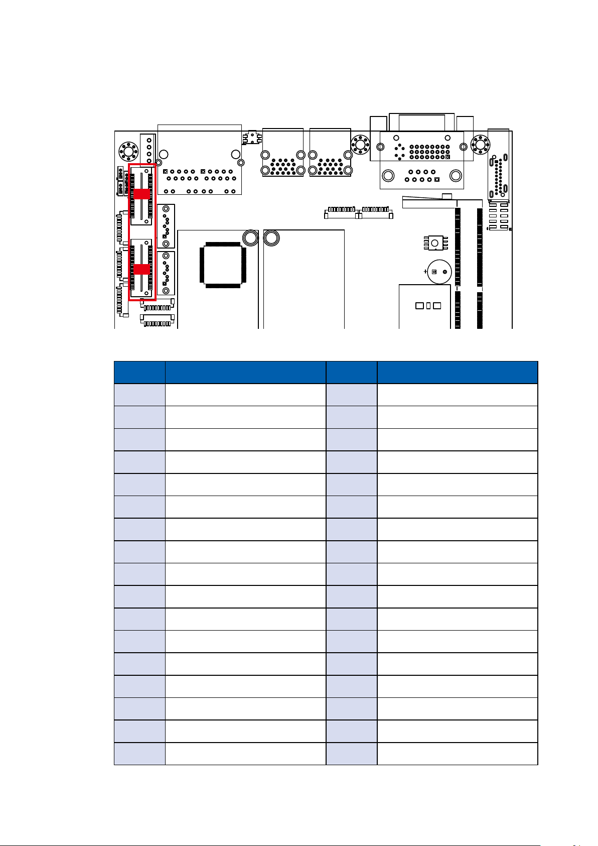
2.4.16 CN6, CN10 : SUMIT
CN10
CN6
CN10 Pin Out
Pin No. Function Pin No. Function
1 +5V_AUX 2 +12V
3 +3.3V 4 SMB_DATA
5 +3.3V 6 SMB_CLK
7 Reserved 8 Reserved
1
2
9
10
9 Reserved 10 Reserved
11 USB_OC# 12 Reserved
13 Reserved 14 Reserved
15 +5V 16 Reserved
17 USB_3+ 18 Reserved
19 USB_3- 20 Reserved
21 +5V 22 Test Point
23 USB_2+ 24 LPC_AD0
25 USB_2- 26 LPC_AD1
27 +5V 28 LPC_AD2
29 USB_1+ 30 LPC_AD3
31 USB_1- 32 LPC_FRAME#
33 +5V 34 SERIRQ#
GETTING TO KNOW YOUR SPC-3000/3500©Vecow SPC-3000/3500 User Manual
90

35 USB_0+ 36 Reserved
37 USB_0- 38 CLK_33MHz
39 GND 40 GND
41 A_PET_P0 42 A_PER_P0
43 A_PET_N0 44 A_PER_N0
45 GND 46 GND
47 PERST# 48 A_CLKP
49 WAKE# 50 A_CLKN
51 +5V 52 GND
CN6 Pin Out
Pin No. Function Pin No. Function
1 GND 2 GND
3 B_PET_P0 4 B_PER_P0
5 B_PET_N0 6 B_PER_N0
7 GND 8 GND
9 C_CLKP 10 B_CLKP
11 C_CLKN 12 B_CLKN
13 CPRSNT#/C_PE_CLKREQ# 14 GND
15 C_PET_P0 16 C_PER_P0
17 C_PET_N0 18 C_PER_N0
19 GND 20 GND
21 C_PET_P1 22 C_PER_P1
23 C_PET_N1 24 C_PER_N1
25 GND 26 GND
27 C_PET_P2 28 C_PER_P2
29 C_PET_N2 30 C_PER_N2
31 GND 32 GND
33 C_PET_P3 34 C_PER_P3
35 C_PET_N3 36 C_PER_N3
GETTING TO KNOW YOUR SPC-3000/3500
91

37 GND 38 GND
39 PERST# 40 WAKE#
41 Reserved 42 Reserved
43 +5V 44 Reserved
45 +5V 46 +3.3V
47 +5V 48 +3.3V
49 +5V 50 +3.3V
51 +5V 52 +5V_AUX
2.4.17 SYS FAN1 : Connector
SYS FAN1
2
1
Fan power connector supports higher thermal requirements.
Pin No. Denition Pin No. Denition
1 +12V 3 FAN_TAC
1
2
9
10
2 FAN_CTL 4 GND
GETTING TO KNOW YOUR SPC-3000/3500©Vecow SPC-3000/3500 User Manual
92

2.4.18 JPMS, JPKB : PS/2 Mouse Keyboard Pin Head
JPKB
JPMS
1
2
9
10
JPMS Mouse Pin assingment
as the following table:
Pin No. Denition
JPMS Keyboard Pin assingment
as the following table:
Pin No. Denition
1 SIO_MCLK
2 SIO_MDAT
3 GND
2.4.19 SPC-3000/3500 PCB Bottom Side
1 SIO_KCLK
2 SIO_KDAT
3 VCC5_KBMS
GETTING TO KNOW YOUR SPC-3000/3500
93
 Loading...