

Vecow SPC-4000, SEC-2220, SEC-2000 Series, SEC-2211 User Manual

USER
Manual
USER
Manual
1.4.0 Edition 20190314
Intel Atom® x7-E3950 (Apollo Lake) Fanless Embedded System,
Ultra-Compact, Rugged, -40°C to 85°C Operation
SPC-4000
ii
©Vecow SPC-4000 User Manual
Version Date Page Description Remark
0.10 11/07/2018 All Preliminary Release
1.00 11/21/2018 All Ocial Release
1.10 01/19/2019 3, 5, 7, 52 Update
1.20 01/25/2019 31 Update
1.30 02/27/2019 28, 43, 44, 46, 47 Update
1.40 03/14/2019 17, 20, 25, 31, 35, 39, 44 Update
Record of Revision

iii
©Vecow SPC-4000 User Manual
This manual is released by Vecow Co., Ltd. for reference purpose only. All
product oerings and specications are subject to change without prior notice. It
does not represent commitment of Vecow Co., Ltd. Vecow shall not be liable for
direct, indirect, special, incidental, or consequential damages arising out of the
use of the product; documentation; or for any infringements upon the rights of
third parties, which may result from such use.
Disclaimer
This equipment has been tested and found to comply with the limits for a Class
A digital device, pursuant to part 15 of the FCC Rules. These limits are designed
to provide reasonable protection against harmful interference when the
equipment is operated in a commercial environment. This equipment generates,
uses, and can radiate radio frequency energy, and if it is not installed and used
in accordance with the instruction manual, it may cause harmful interference to
radio communications. Operation of this equipment in a residential area is likely
to cause harmful interference in which case the user will be required to correct
the interference at his own expense.
FCC
The products described in this manual comply with all applicable European
Union (CE) directives if it has a CE marking. For computer systems to
remain CE compliant, only CE-compliant parts may be used. Maintaining CE
compliance also requires proper cable and cabling techniques.
CE
Declaration of Conformity
This document contains proprietary information protected by copyright. No part
of this publication may be reproduced in any form or by any means, electric,
photocopying, recording or otherwise, without prior written authorization
by Vecow Co., Ltd. The rights of all the brand names, product names and
trademarks belong to their respective owners.
Copyright and Trademarks
iv
©Vecow SPC-4000 User Manual
Part Number Description
SPC-4010
SPC-4000, Intel Atom® x7-E3950 SoC, 2 GigE LAN support IEEE
1588 (PTP), 2 Isolated COM, 4 USB, 1 SIM, 12V DC power input
SPC-4020
SPC-4000, Intel Atom
®
x7-E3950 SoC, 2 GigE LAN support IEEE
1588 (PTP), 4 COM with 2 Isolated, 16 Isolated DIO, 4 USB, 1 SIM,
12V DC power input
SPC-4020A
SPC-4000, Intel Atom
®
x7-E3950 SoC, 2 GigE LAN support IEEE
1588 (PTP), 4 COM with 2 Isolated, 16 Isolated DIO, 4 USB, 1 SIM,
9V to 36V wide range DC power input
Order Information
v
©Vecow SPC-4000 User Manual
Part Number Description
DDR3L8G Certied DDR3L-1866/1600 8G RAM
DDR3L4G Certied DDR3L-1866/1600 4G RAM
PWA-160W-WT-12V
160W, 12V, 85V AC to 264V AC Power Adapter with 3-pin
Terminal Block, Wide Temperature -30°C to +70°C
PWA-160W-WT
160W, 24V, 85V AC to 264V AC Power Adapter with 3-pin
Terminal Block, Wide Temperature -30°C to +70°C
PWA-120W-12V
120W, 12V, 90V AC to 264V AC Power Adapter with 3-pin
Terminal Block
PWA-120W
120W, 24V, 90V AC to 264V AC Power Adapter with 3-pin
Terminal Block
TMK2-20P-100 Terminal Block 20-pin to Terminal Block 20-pin Cable, 100cm
TMK2-20P-500 Terminal Block 20-pin to Terminal Block 20-pin Cable, 500cm
TMB-TMBK-20P
Terminal Board with One 20-pin Terminal Block Connector and
DIN-Rail Mounting
4G Module Mini PCIe 4G/GPS Module with Antenna
WiFi & Bluetooth WiFi & Bluetooth Module with Antenna
Order Accessories

vi
©Vecow SPC-4000 User Manual
Table of Contents
CHAPTER 1 GENERAL INTRODUCTION 1
1.1 Overview 1
1.2 Features 2
1.3 Product Specication 3
1.3.1 Specications of SPC-4010 3
1.3.2 Specications of SPC-4020 5
1.3.3 Specications of SPC-4020A 7
1.4 Mechanical Dimension 9
1.4.1 Dimensions of SPC-4010 9
1.4.2 Dimensions of SPC-4020 9
1.4.3 Dimensions of SPC-4020A 9
CHAPTER 2 GETTING TO KNOW YOUR SPC-4000 10
2.1 Packing List 10
2.2 Front Panel I/O & Functions 13
2.3 Rear Panel I/O & Functions 24
2.4 Main Board Expansion Connectors 28
2.5 Main Board Jumper Settings 45
CHAPTER 3 SYSTEM SETUP 48
3.1 How to Open Your SPC-4000 48
3.2 Installing DDR3L Module 52
3.3 Installing Mini PCIe Card 55
3.4 Installing Antenna Cable 57
3.5 Installing SIM Card 58
3.6 Installing SSD/HDD 60
3.7 Mounting Your SPC-4000 63

vii
©Vecow SPC-4000 User Manual
CHAPTER 4 BIOS SETUP 64
4.1 Entering Setup 64
4.2 Main Menu 65
4.3 Advanced 65
4.4 Chipset 71
4.5 Security 77
4.6 Boot 78
4.7 Save & Exit 79
APPENDIX A : Isolated DIO Guide 80
APPENDIX B : Software Functions 85
APPENDIX C : RAID Functions 88
APPENDIX D : Power Consumption 92
APPENDIX E : Supported Memory & Storage List 94

1
©Vecow SPC-4000 User Manual
GENERAL INTRODUCTION
GENERAL INTRODUCTION
1.1 Overview
SPC-4000 is an Ultra-compact Fanless Embedded Box for smart industrialgrade IoT applications. With low-power quad-core Intel Atom® x7-E3950
processor (Apollo Lake) engine, single DDR3L SO-DIMM supports up to 8GB
memory; Advanced Intel® HD graphics 505 supports DirectX 12, OpenGL 4.3
and OpenCL 2.1 API, up to 4K resolution; Vecow SPC-4000 delivers more than
150% system performance improved and up to 300% graphics performance
enhanced than the embedded engine powered by the former generation Intel
Atom® E3845 SoC.
Supports VGA and lockable HDMI dual display, built-in dual GigE LAN
supporting IEEE 1588 Precision Time Protocol (PTP), 4 COM RS-232/422/485
with 2 Isolated protection, 1 SIM for WiFi/4G/3G/LTE/GPRS/UMTS, 6 USB, 3
Mini PCIe, 1 SATA III, 1 M.2 for expansion, 16 Isolated DIO, 9V to 36V wide
range power input or 12V DC-in, remote power switch, rugged design for
fanless -40°C to 85°C operation, Vecow SPC-4000 features compact integrated
functions with flexible configurations to meet your requirements for smart
embedded applications.
With outstanding system performance, compact integrated functions, rugged
reliability, system-oriented solution and versatile configurations, Vecow
SPC-4000 Series Rugged Embedded System is your smart solution for Machine
Vision, Smart Manufacturing, Factory Automation, ITS (Intelligent Transportation
System), Digital Signage, Public Infotainment or any Industrial IoT/Industry 4.0
applications.
1

2
©Vecow SPC-4000 User Manual
GENERAL INTRODUCTION
1.2 Features
• Quad Core Intel Atom® x7-E3950 SoC (Apollo Lake-I) supports lower power
consumption
• Fanless, -40°C to 85°C Extended Operating Temperature
• DDR3L 1866MHz Memory, up to 8GB
• Supports Lockable HDMI and VGA Dual Display, up to 4K resolution
• 2 Independent GigE LAN support IEEE 1588 (PTP)
• 4 COM RS-232/422/485 with 2 Isolated
• 16 Isolated DIO, 6 USB, 1 SIM Socket
• 3 Mini PCIe, 1 SATA III, 1 M.2
• 12V to 36V DC Power Input, optional supports 9V to 36V wide range DC
Power Input
• TPM 2.0 supported
3
©Vecow SPC-4000 User Manual
GENERAL INTRODUCTION
1.3 Product Specication
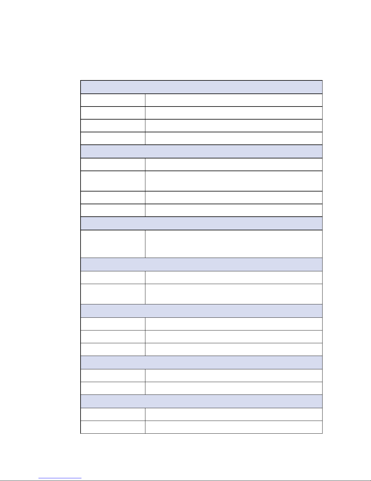
1.3.1 Specications of SPC-4010
System
Processor Intel Atom® x7-E3950 processor (Apollo Lake-I)
BIOS AMI
SIO IT8786E
Memory 1 DDR3L 1866MHz SO-DIMM, up to 8GB (Non-ECC)
I/O Interface
Serial 2 Isolated COM RS-232/422/485
USB • 2 USB 3.0 (External)
• 4 USB 2.0 (2 External, 2 Internal)
LED Power, HDD, wireless
SIM 1 Internal SIM socket
Expansion
Mini PCIe 2 Mini PCIe sockets :
• 1 Mini PCIe for PCIe/USB/SIM card
• 1 Mini PCIe for PCIe/USB/Optional mSATA
Graphics
Graphics Processor Intel® HD graphics 505
Interface • HDMI : Up to 3840 x 2160 @30Hz (Lockable)
• VGA : Up to 1920 x 1440 @60Hz
Storage
SATA 1 SATA III (6Gbps)
mSATA 1 SATA III (Mini PCIe type, 6Gbps)
Storage Device 1 2.5" SSD/HDD bracket (Internal)
Audio
Audio Codec Realtek ALC892, 5.1 Channel HD Audio
Audio Interface 1 Mic-in, 1 Line-out
Ethernet
LAN 1 Intel® I210 GigE LAN supports IEEE 1588
LAN 2 Intel
®
I210 GigE LAN supports IEEE 1588

4
©Vecow SPC-4000 User Manual
GENERAL INTRODUCTION
Power
Power Input Single 12V DC power input
Power Interface 3-pin Terminal Block : V+, V-, Frame Ground
Remote Switch 2-pin Terminal Block
Others
TPM Optional Inneon SLB9665 supports TPM 2.0, LPC interface
Watchdog Timer Reset : 1 to 255 sec./min. per step
HW Monitor Monitoring temperature, voltages. Auto throttling control when
CPU overheats.
Software Support
OS Windows 10, Linux
Mechanical
Dimension (W) 111mm x (L) 155mm x (H) 44mm (4.4" x 6.1" x 1.7")
Weight 0.8 kg (1.84 lb)
Mounting • Wallmount by mounting bracket
• DIN Rail mount (Optional)
• 2U Rackmount (Optional)
Environment
Operating
Temperature
-40°C to 85°C (-40°F to 185°F)
Storage Temperature -40°C to 85°C (-40°F to 185°F)
Humidity 5% to 95% Humidity, non-condensing
Relative Humidity 95% at 85°C
Shock • IEC 60068-2-27
• SSD : 50G @ wallmount, Half-sine, 11ms
Vibration • IEC 60068-2-64
• SSD : 5Grms, 5Hz to 500Hz, 3 Axis
EMC CE, FCC, EN50155, EN50121-3-2
5
©Vecow SPC-4000 User Manual
GENERAL INTRODUCTION
1.3.2 Specications of SPC-4020
System
Processor Intel Atom® x7-E3950 processor (Apollo Lake-I)
BIOS AMI
SIO IT8786E
Memory 1 DDR3L 1866MHz SO-DIMM, up to 8GB (Non-ECC)
I/O Interface
Serial 4 COM RS-232/422/485 with 2 Isolated
USB • 2 USB 3.0 (External)
• 4 USB 2.0 (2 External, 2 Internal)
DIO 16 Isolated DIO : 8 DI, 8 DO
LED Power, HDD, wireless
SIM 1 Internal SIM socket
Expansion
Mini PCIe 3 Mini PCIe sockets :
• 1 Mini PCIe for PCIe/USB/SIM card
• 1 Mini PCIe for PCIe/USB/Optional mSATA
• 1 Mini PCIe for PCIe/USB
M.2 1 M.2 Key B socket
Graphics
Graphics Processor Intel® HD graphics 505
Interface • HDMI : Up to 3840 x 2160 @30Hz (Lockable)
• VGA : Up to 1920 x 1440 @60Hz
Storage
SATA 1 SATA III (6Gbps)
mSATA 1 SATA III (Mini PCIe type, 6Gbps)
Storage Device 1 2.5" SSD/HDD bracket (Internal)
Audio
Audio Codec Realtek ALC892, 5.1 Channel HD Audio
Audio Interface 1 Mic-in, 1 Line-out
Ethernet
LAN 1 Intel® I210 GigE LAN supports IEEE 1588
LAN 2 Intel
®
I210 GigE LAN supports IEEE 1588
6
©Vecow SPC-4000 User Manual
GENERAL INTRODUCTION
Power
Power Input Single 12V DC power input
Power Interface 3-pin Terminal Block : V+, V-, Frame Ground
Remote Switch 2-pin Terminal Block
Others
TPM Optional Inneon SLB9665 supports TPM 2.0, LPC interface
Watchdog Timer Reset : 1 to 255 sec./min. per step
HW Monitor Monitoring temperature, voltages. Auto throttling control when
CPU overheats.
Software Support
OS Windows 10, Linux
Mechanical
Dimension (W) 111mm x (L) 155mm x (H) 68mm (4.4" x 6.1" x 2.7")
Weight 1.1 kg (2.34 lb)
Mounting • Wallmount by mounting bracket
• DIN Rail mount (Optional)
• 2U Rackmount (Optional)
Environment
Operating
Temperature
-40°C to 85°C (-40°F to 185°F)
Storage Temperature -40°C to 85°C (-40°F to 185°F)
Humidity 5% to 95% Humidity, non-condensing
Relative Humidity 95% at 85°C
Shock • IEC 60068-2-27
• SSD : 50G @ wallmount, Half-sine, 11ms
Vibration • IEC 60068-2-64
• SSD : 5Grms, 5Hz to 500Hz, 3 Axis
EMC CE, FCC, EN50155, EN50121-3-2
7
©Vecow SPC-4000 User Manual
GENERAL INTRODUCTION
1.3.3 Specications of SPC-4020A
System
Processor Intel Atom® x7-E3950 processor (Apollo Lake-I)
BIOS AMI
SIO IT8786E
Memory 1 DDR3L 1866MHz SO-DIMM, up to 8GB (Non-ECC)
I/O Interface
Serial 4 COM RS-232/422/485 with 2 Isolated
USB • 2 USB 3.0 (External)
• 4 USB 2.0 (2 External, 2 Internal)
DIO 16 Isolated DIO : 8 DI, 8 DO
LED Power, HDD, wireless
SIM 1 Internal SIM socket
Expansion
Mini PCIe 3 Mini PCIe sockets :
• 1 Mini PCIe for PCIe/USB/SIM card
• 1 Mini PCIe for PCIe/USB/Optional mSATA
• 1 Mini PCIe for PCIe/USB
M.2 1 M.2 Key B socket
Graphics
Graphics Processor Intel® HD graphics 505
Interface • HDMI : Up to 3840 x 2160 @30Hz (Lockable)
• VGA : Up to 1920 x 1440 @60Hz
Storage
SATA 1 SATA III (6Gbps)
mSATA 1 SATA III (Mini PCIe type, 6Gbps)
Storage Device 1 2.5" SSD/HDD bracket (Internal)
Audio
Audio Codec Realtek ALC892, 5.1 Channel HD Audio
Audio Interface 1 Mic-in, 1 Line-out
Ethernet
LAN 1 Intel® I210 GigE LAN supports IEEE 1588
LAN 2 Intel
®
I210 GigE LAN supports IEEE 1588

8
©Vecow SPC-4000 User Manual
GENERAL INTRODUCTION
Power
Power Input 9V to 36V DC power input
Power Interface 3-pin Terminal Block : V+, V-, Frame Ground
Remote Switch 2-pin Terminal Block
Others
TPM Optional Inneon SLB9665 supports TPM 2.0, LPC interface
Watchdog Timer Reset : 1 to 255 sec./min. per step
HW Monitor Monitoring temperature, voltages. Auto throttling control when
CPU overheats.
Software Support
OS Windows 10, Linux
Mechanical
Dimension (W) 111mm x (L) 155mm x (H) 84mm (4.4" x 6.1" x 3.3")
Weight 1.1 kg (2.34 lb)
Mounting • Wallmount by mounting bracket
• DIN Rail mount (Optional)
• 2U Rackmount (Optional)
Environment
Operating
Temperature
-40°C to 85°C (-40°F to 185°F)
Storage Temperature -40°C to 85°C (-40°F to 185°F)
Humidity 5% to 95% Humidity, non-condensing
Relative Humidity 95% at 85°C
Shock • IEC 60068-2-27
• SSD : 50G @ wallmount, Half-sine, 11ms
Vibration • IEC 60068-2-64
• SSD : 5Grms, 5Hz to 500Hz, 3 Axis
EMC CE, FCC, EN50155, EN50121-3-2
9
©Vecow SPC-4000 User Manual
GENERAL INTRODUCTION
1.4 Mechanical Dimension
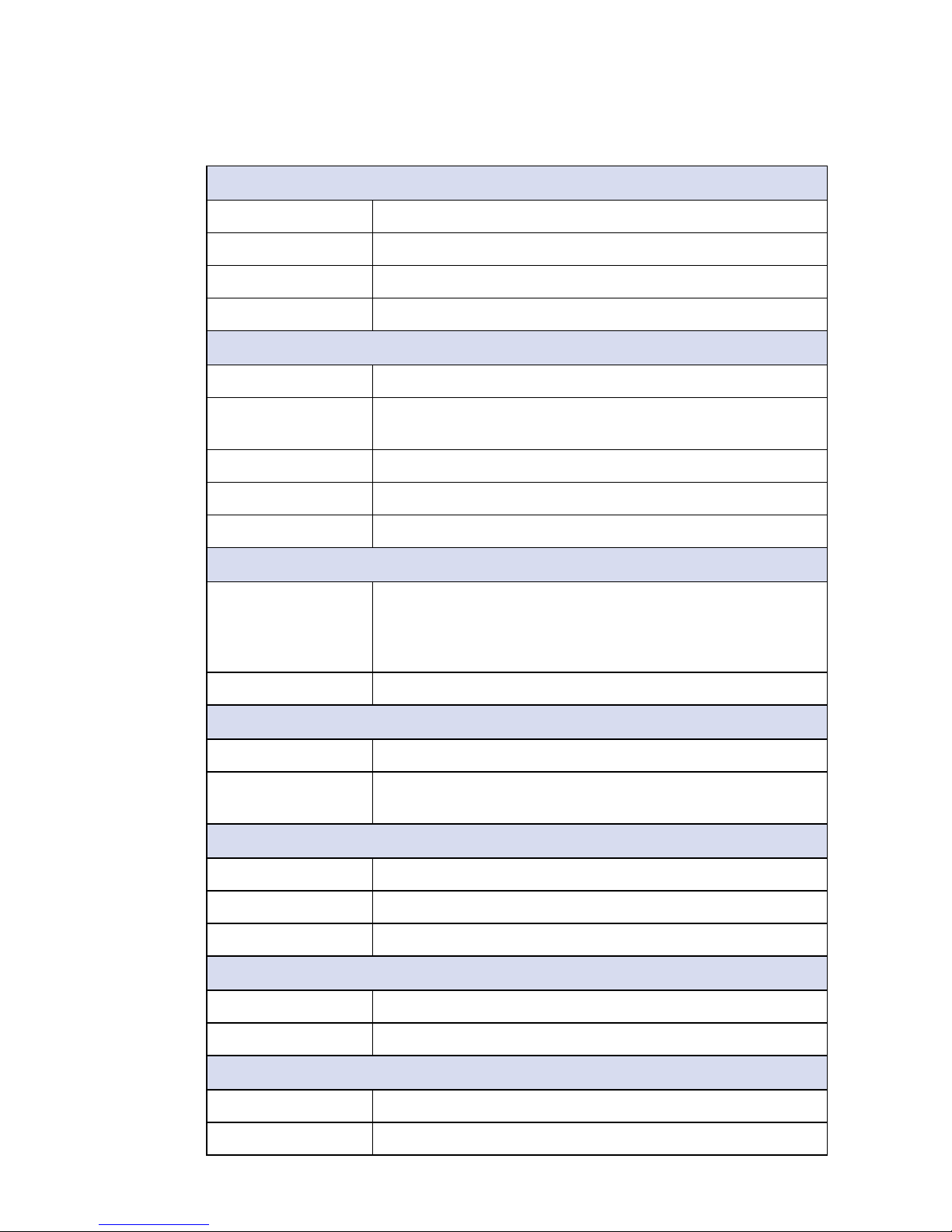
1.4.1 Dimensions of SPC-4010
155.4 (6.1”)
174.1 (6.9”)
190.4 (7.5”)
53.8 (2.1”)
85.8 (3.4”)
111.1 (4.4”)
44.0 (1.7”)
A
5.0 (0.20”)
25.0 (0.98”)
Ø9.0 (Ø0.35”
)
32.6 (1.3”) 45.8 (1.8”)
111.0 (4.4”)
7.6 (0.3”)
A Detail
2:1
Unit : mm (inch)
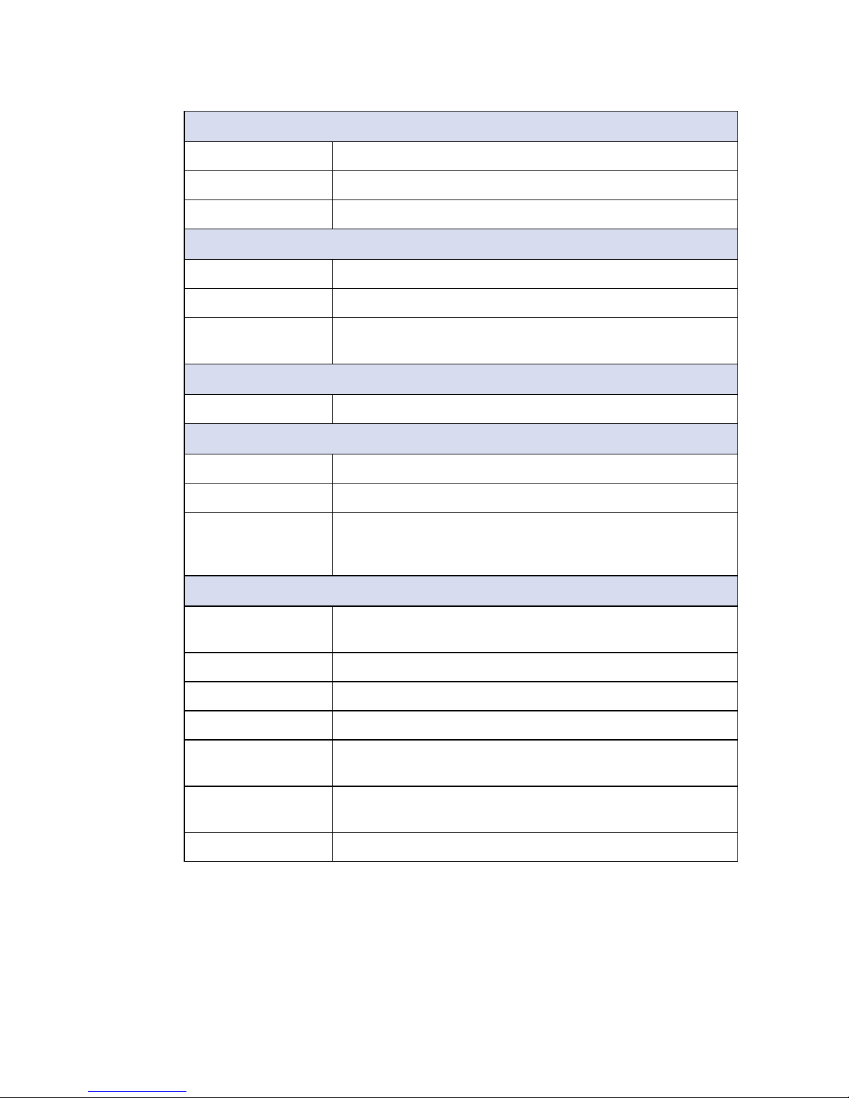
1.4.2 Dimensions of SPC-4020
155.4 (6.1”)
174.1 (6.9”)
190.4 (7.5”)
53.8 (2.1”)
85.8 (3.4”)
111.1 (4.4”)
68.1 (2.7”)
A
5.0 (0.20”)
25.0 (0.98”)
Ø9.0 (Ø0.35”
)
32.6 (1.3”) 45.8 (1.8”)
111.0 (4.4”)
7.6 (0.3”)
A Detail
2:1
Unit : mm (inch)
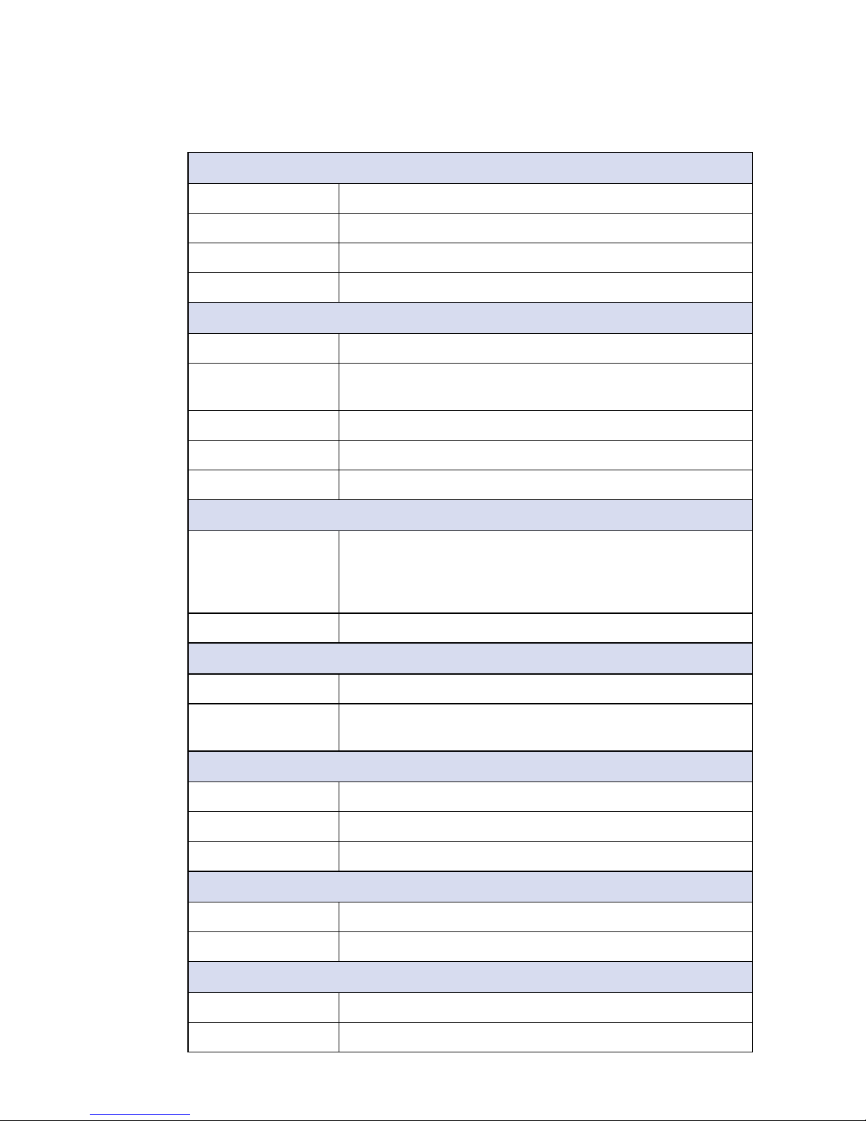
1.4.3 Dimensions of SPC-4020A
155.4 (6.1”)
174.1 (6.9”)
190.4 (7.5”)
53.8 (2.1”)
85.8 (3.4”)
111.1 (4.4”)
89.0 (3.5”)
84.0 (3.3”)
A
5.0 (0.20”)
25.0 (0.98”)
Ø9.0 (Ø0.35”
)
32.6 (1.3”) 45.8 (1.8”)
111.0 (4.4”)
7.6 (0.3”)
A Detail
2:1
Unit : mm (inch)
10
©Vecow SPC-4000 User Manual
GETTING TO KNOW YOUR SPC-4000
2
GETTING TO KNOW YOUR SPC-4000
2.1 Packing List
2.1.1 Packing List for SPC-4010
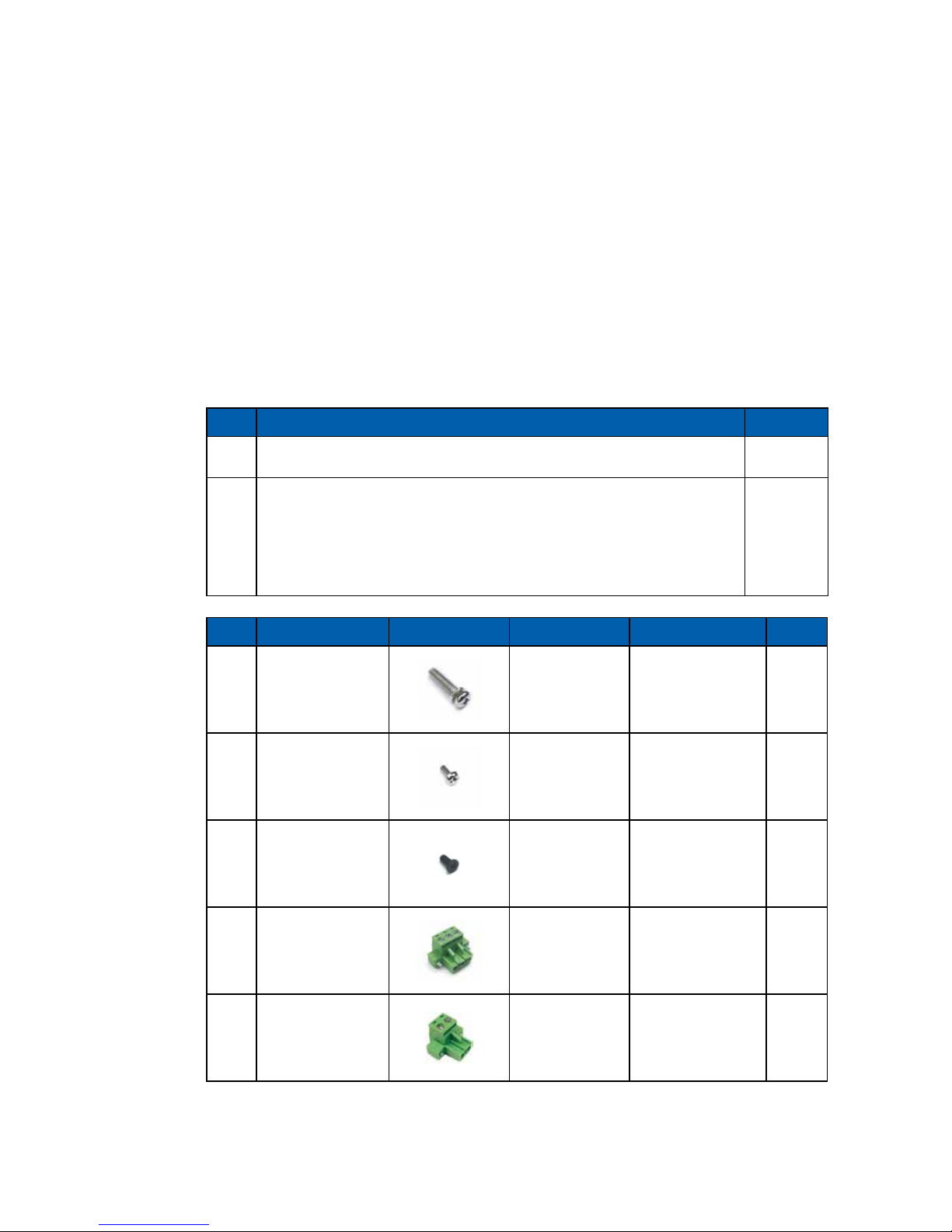
Item Description Qty
1 SPC-4010 Embedded System 1
2 SPC-4010 accessory box, which contains
• Vecow Drivers & Utilities DVD
• Wall-mounting bracket
• Foot Pad
• Screws & Terminal block
1
2
4
(Below)
Item Description Outlook Usage P/N Qty
1
PHILLPIS
M4x16L with
washer, Ni
Mount 53-24D6416-30B 4
2
PHILLPIS
M2.5x6L, Ni
Mini PCIe slot 53-2426906-30B 2
3
PHILLPIS
M3x6L
Wall mount
bracket/SSD/
HDD
53-2450000-215 8
4
Terminal block
3-pin (5.0mm)
DC-IN 51-2411R03-S1B 1
5
Terminal block
2-pin (5.0mm)
Switch 51-2411R02-S1B 1

11
©Vecow SPC-4000 User Manual
GETTING TO KNOW YOUR SPC-4000
2.1.2 Packing List for SPC-4020
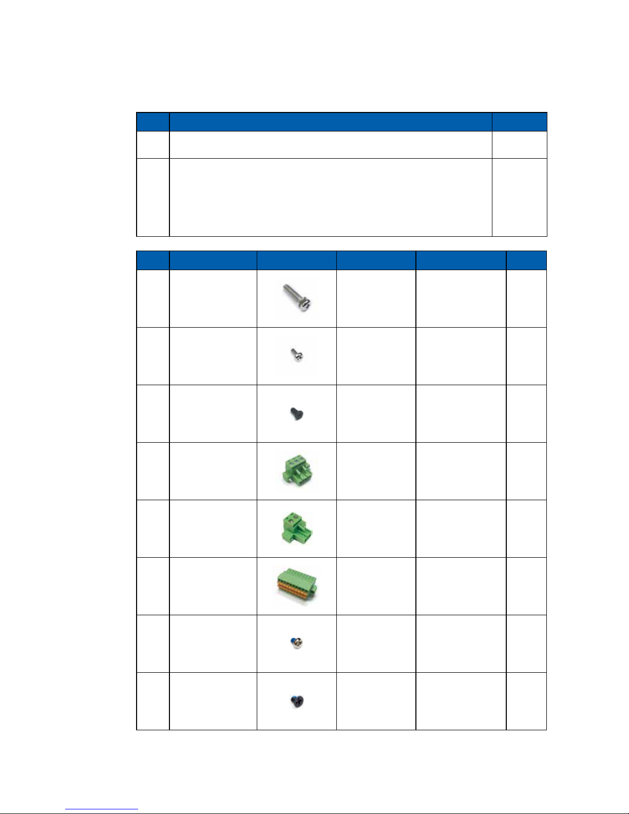
Item Description Qty
1 SPC-4020 Embedded System 1
2 SPC-4020 accessory box, which contains
• Vecow Drivers & Utilities DVD
• Wall-mounting bracket
• Foot Pad
• Screws & Terminal block
1
2
4
(Below)
Item Description Outlook Usage P/N Qty
1
PHILLPIS
M4x16L with
washer, Ni
Mount 53-24D6416-30B 4
2
PHILLPIS
M2.5x6L, Ni
Mini PCIe slot 53-2426906-30B 3
3
PHILLPIS
M3x6L
Wall mount
bracket/SSD/
HDD
53-2450000-215 8
4
Terminal block
3-pin (5.0mm)
DC-IN/Switch 51-2411R03-S1B 2
5
Terminal block
2-pin (5.0mm)
Switch 51-2411R02-S1B 1
6
Terminal block
20-pin (2.54mm)
Isolated DIO/
GPIO
51-2112R20-S1D 1
7
PHILLPIS
M3x4L, Ni
M.2 53-2426204-80B 1
12
©Vecow SPC-4000 User Manual
GETTING TO KNOW YOUR SPC-4000
2.1.3 Packing List for SPC-4020A
Item Description Qty
1 SPC-4020A Embedded System 1
2 SPC-4020A accessory box, which contains
• Vecow Drivers & Utilities DVD
• Wall-mounting bracket
• Foot Pad
• Screws & Terminal block
1
2
4
(Below)
Item Description Outlook Usage P/N Qty
1
PHILLPIS
M4x16L with
washer, Ni
Mount 53-24D6416-30B 4
2
PHILLPIS
M2.5x6L, Ni
Mini PCIe slot 53-2426906-30B 3
3
PHILLPIS
M3x6L
Wall mount
bracket
53-2450000-215 4
4
Terminal block
3-pin (5.0mm)
DC-IN/Switch 51-2411R03-S1B 2
5
Terminal block
2-pin (5.0mm)
Switch 51-2411R02-S1B 1
6
Terminal block
20-pin (2.54mm)
Isolated DIO/
GPIO
51-2112R20-S1D 1
7
PHILLPIS
M3x4L, Ni
M.2 53-2426204-80B 1
8
PHILLPIS
M3x4L
SSD/HDD 53-M000450-301 4
13
©Vecow SPC-4000 User Manual
GETTING TO KNOW YOUR SPC-4000
2.2 Front Panel I/O & Functions
In Vecow's SPC-4000 series family, most of the general connections to the
computer device, such as audio, USB, VGA, LAN Jack, Isolated COM and
HDMI, are placed on the front panel.
2.2.1 SPC-4010 Front I/O & Functions
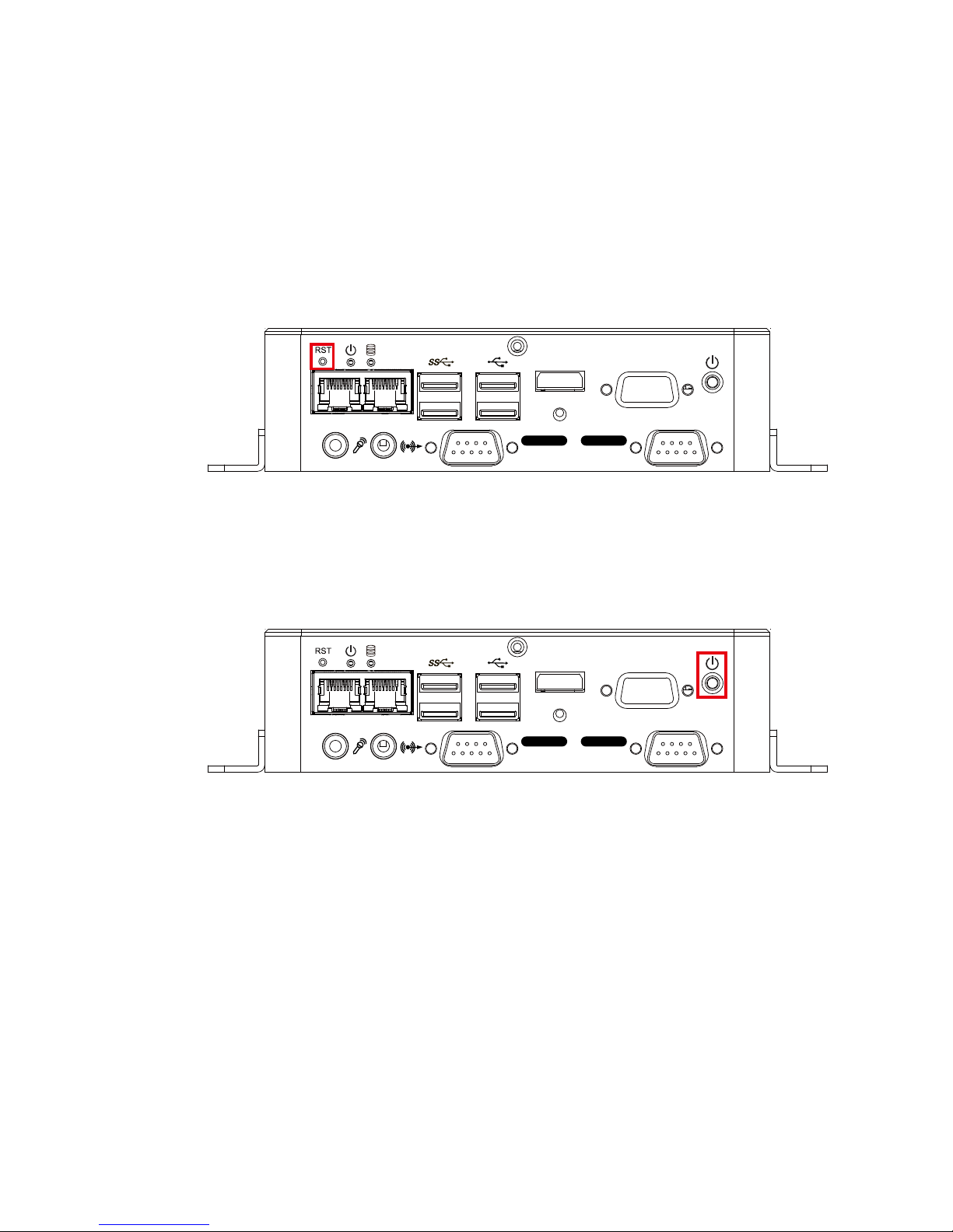
2.2.1.1 Reset Tact Switch
It is a hardware reset switch. Use this switch to reset the system without power
o the system. Press the Reset Switch for a few seconds, and then the reset
function will be enabled.
VGAHDMI
LAN 1 LAN 2
Isolated
COM 2
Isolated
COM 1
2.2.1.2 Power Button
The Power Button is a non-latched switch. To power on the system, press the
power button and then the Green LED is lightened. To power o the system, you
can either command shutdown by OS operation or just simply press the power
button. If system error, you can just press the power button for 4 seconds to shut
down the machine directly. Please do note that a 4-second interval between
each 2 power-on/power-o operation is necessary in normal working status. (For
example, once turning o the system, you have to wait for 4 seconds to initiate
another power-on operation.)
VGAHDMI
LAN 1 LAN 2
Isolated
COM 2
Isolated
COM 1
14
©Vecow SPC-4000 User Manual
GETTING TO KNOW YOUR SPC-4000
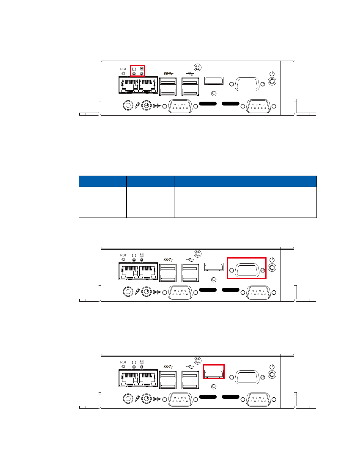
2.2.1.3 PWR and HDD LED Indicator
Power LED/Green (Left) : If the LED is solid green, it indicates that the system
is powered on.
HDD LED/Orange (Right) : If the LED is on, it indicates that the system's storage
is functional. If it is o, it indicates that the system's storage is not functional. If it
is ashing, it indicates data access activities.
LED Color Indication System Status
Orange HDD
On/O : Storage status, function or not.
Twinkling : Data transferring.
Green Power System power status (on/o)
VGAHDMI
LAN 1 LAN 2
Isolated
COM 2
Isolated
COM 1
2.2.1.4 VGA
Onboard VGA Port supports auxiliary channel mode. The connection supports
up to 1920 x 1440 resolution at 60Hz.
VGAHDMI
LAN 1 LAN 2
Isolated
COM 2
Isolated
COM 1
2.2.1.5 HDMI
Onboard HDMI Port supports DDC channel mode. The connection supports up
to 3840 x 2160 resolution at 30Hz.
VGAHDMI
LAN 1 LAN 2
Isolated
COM 2
Isolated
COM 1
15
©Vecow SPC-4000 User Manual
GETTING TO KNOW YOUR SPC-4000
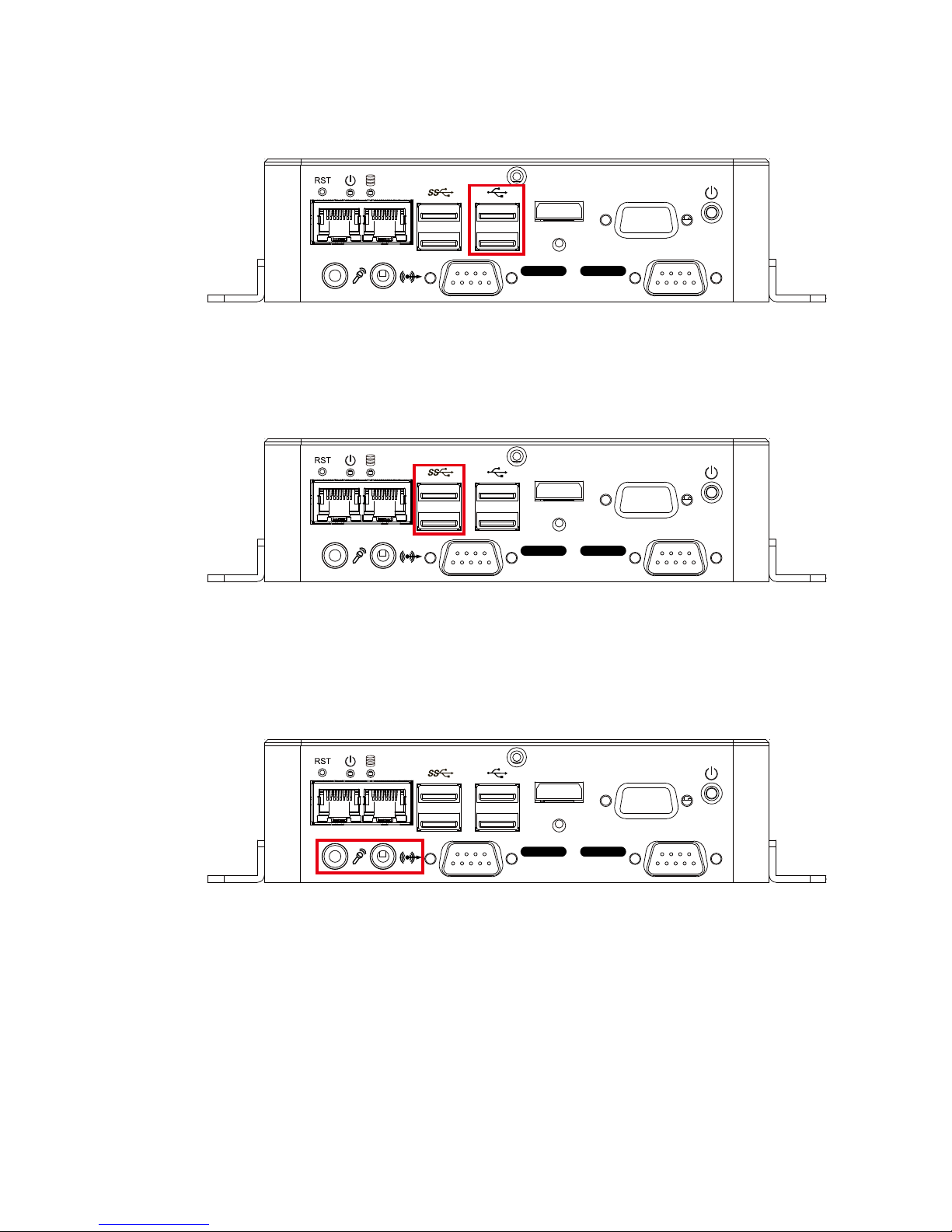
2.2.1.6 USB 2.0
There are 2 USB 2.0 connections available supporting up to 480MB per second
data rate.
VGAHDMI
LAN 1 LAN 2
Isolated
COM 2
Isolated
COM 1
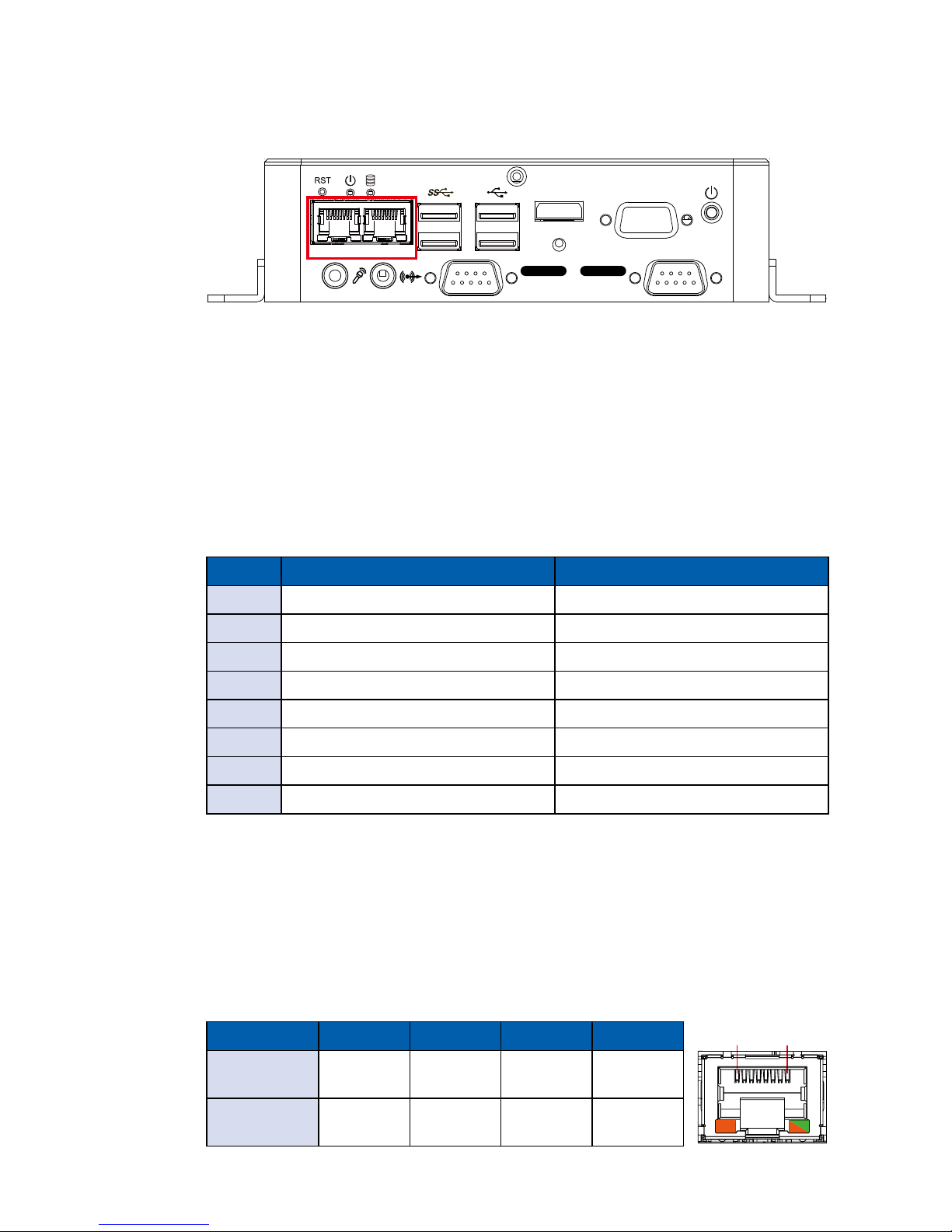
2.2.1.7 USB 3.0
There are 2 USB 3.0 connections available supporting up to 5GB per second
data rate. It is also compliant with the requirements of Super Speed (SS), High
Speed (HS), Full Speed (FS) and Low Speed (LS).
VGAHDMI
LAN 1 LAN 2
Isolated
COM 2
Isolated
COM 1
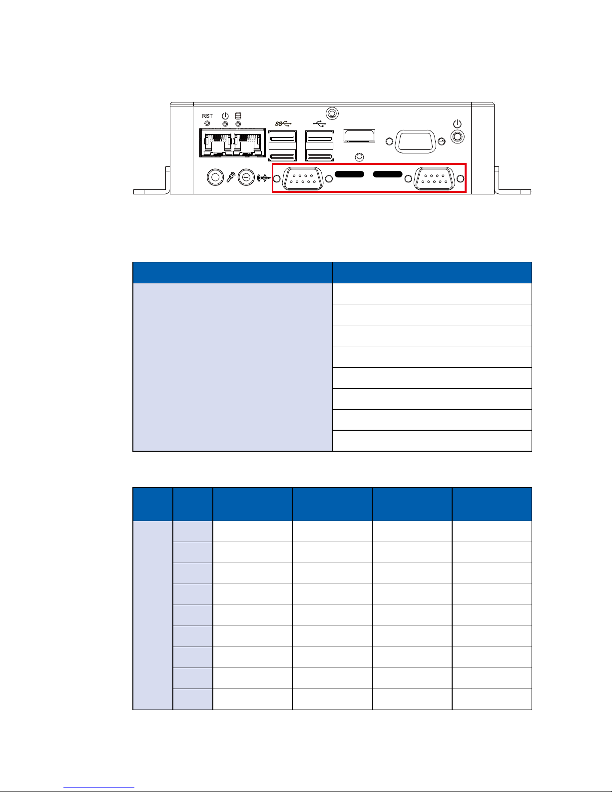
2.2.1.8 Audio Jack
There are 2 audio connectors, Mic-in (Left) and Line-out (Right), in the front
side of SPC-4010. Onboard Realtek ALC892 audio codec supports 5.1
channel HD audio and fully complies with Intel® High Denition Audio (Azalia)
specifications. To utilize the audio function in Windows platform, you need to
install corresponding drivers for Realtek ALC892 codec.
VGAHDMI
LAN 1 LAN 2
Isolated
COM 2
Isolated
COM 1
16
©Vecow SPC-4000 User Manual
GETTING TO KNOW YOUR SPC-4000
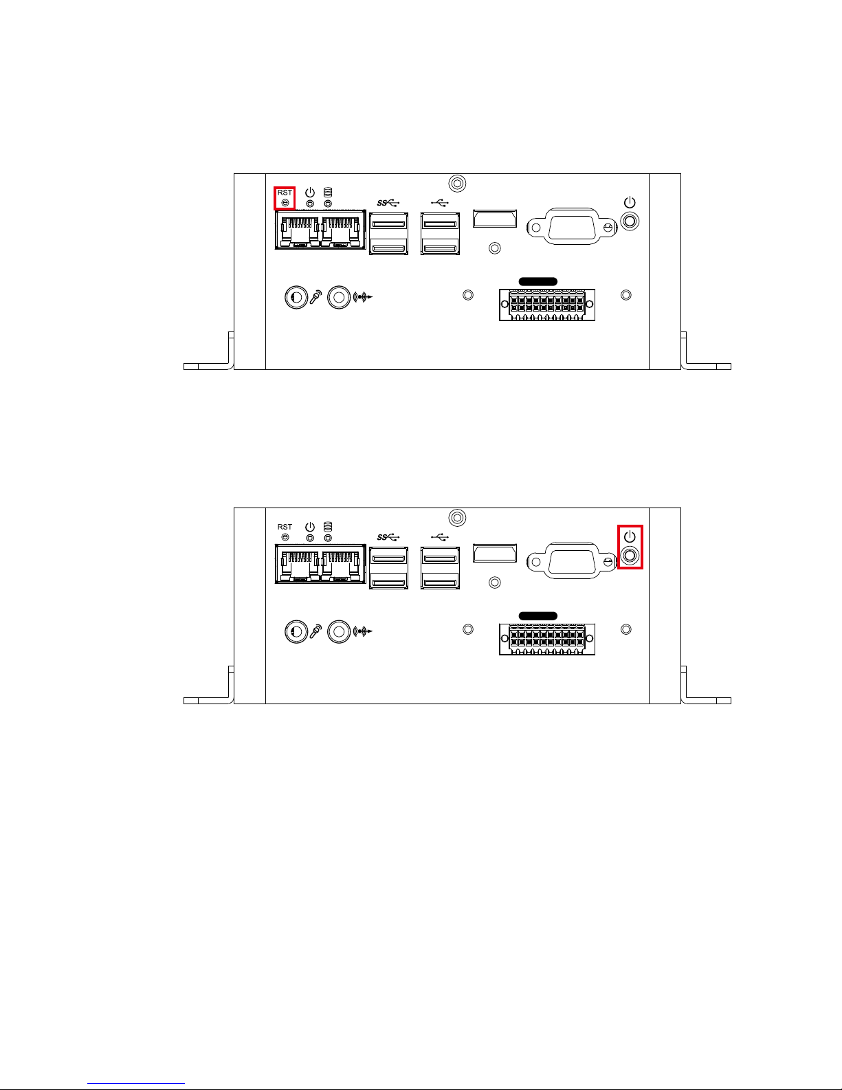
2.2.1.9 10/100/1000 Mbps Ethernet Port
There are 2 8-pin RJ-45 jacks supporting 10/100/1000 Mbps Ethernet
connections in the front side of SPC-4010. LAN 1 (Left side) and LAN 2 (Right
side) are powered by Intel® I210 Ethernet engine with IEEE 1588, The Precision
Time Protocol (PTP) function. When both LAN 1 and LAN 2 work in normal
status, basic iAMT function is enabled.
Using suitable RJ-45 cable, you can connect SPC-4010 system to a computer,
or to any other devices with Ethernet connection; for example, a hub or a switch.
Moreover, both LAN 1 and LAN 2 support Wake on LAN and Pre-boot functions.
The pinouts of LAN 1 and LAN 2 are listed as follows :
Pin No. 10/100 Mbps 1000Mbps
1 E_TX+ MDI0_P
2 E_TX- MDI0_N
3 E_RX+ MDI1_P
4 ----- MDI2_P
5 ----- MDI2_N
6 E_RX- MDI1_N
7 ----- MDI3_P
8 ----- MDI3_N
VGAHDMI
LAN 1 LAN 2
Isolated
COM 2
Isolated
COM 1
Each LAN port is supported by standard RJ-45 connector with LED indicators to
present Active/Link/Speed status of the connection.
The LED indicator on the right bottom corner lightens in solid green when the
cable is properly connected to a 100Mbps Ethernet network; The LED indicator
on the right bottom corner lightens in solid orange when the cable is properly
connected to a 1000Mbps Ethernet network; The left LED will keep twinkling/o
when Ethernet data packets are being transmitted/received.
LED Location LED Color 10Mbps 100Mbps 1000Mbps
Right
Green/
Orange
O
Solid
Green
Solid
Orange
Left Yellow
Twinkling
Yellow
Twinkling
Yellow
Twinkling
Yellow
1 8
17
©Vecow SPC-4000 User Manual
GETTING TO KNOW YOUR SPC-4000
2.2.1.10 Serial Port COM (Isolated)
Serial port can be configured for RS-232, RS-422, or RS-485 with auto flow
control communication. The default denition is RS-232. If you want to change
to RS-422 or RS-485, you can nd the setting in BIOS.
BIOS Setting Function
COM 1
COM 2
RS-232
RS-422 (5-wire)
RS-422 (9-wire)
RS-485
RS-485 w/z auto-ow control
MDI1_N
MDI3_P
MDI3_N
COM 1/COM 2 pin assignments are listed in the following table :
Serial
Port
Pin
No.
RS-232
RS-422
(5-wire)
RS-422
(9-wire)
RS-485
(3-wire)
1 to 4
1 DCD TXD- TXD- DATA-
2 RXD TXD+ TXD+ DATA+
3 TXD RXD+ RXD+ -----------
4 DTR RXD- RXD- -----------
5 GND GND GND GND
6 DSR ----------- RTS- -----------
7 RTS ----------- RTS+ -----------
8 CTS ----------- CTS+ -----------
9 RT ----------- CTS- -----------
VGAHDMI
LAN 1 LAN 2
Isolated
COM 2
Isolated
COM 1
18
©Vecow SPC-4000 User Manual
GETTING TO KNOW YOUR SPC-4000
2.2.2 SPC-4020/SPC-4020A Front I/O & Functions
2.2.2.1 Reset Tact Switch
It is a hardware reset switch. Use this switch to reset the system without power
off the system. Press the Reset Switch for a few seconds, then reset will be
enabled.
VGAHDMI
LAN 1 LAN 2
Isolated
DIO
2.2.2.2 Power Button
The Power Button is a non-latched switch. To power on the system, press the
power button and then the Green LED is lightened. To power o the system, you
can either command shutdown by OS operation or just simply press the power
button. If system error, you can just press the power button for 4 seconds to shut
down the machine directly. Please do note that a 4-second interval between
each 2 power-on/power-o operation is necessary in normal working status. (For
example, once turning o the system, you have to wait for 4 seconds to initiate
another power-on operation).
VGAHDMI
LAN 1 LAN 2
Isolated
DIO
19
©Vecow SPC-4000 User Manual
GETTING TO KNOW YOUR SPC-4000
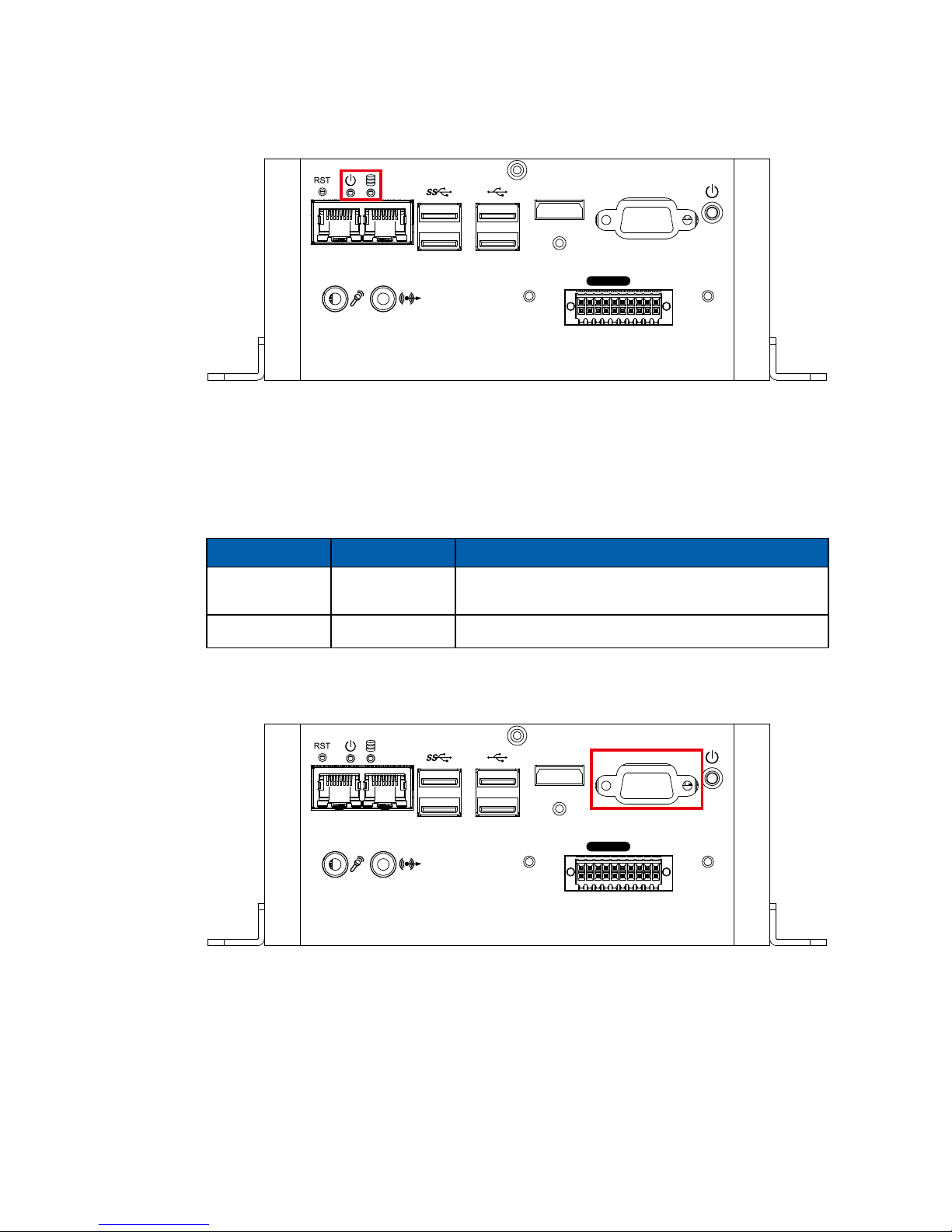
2.2.2.3 PWR and HDD LED Indicator
Power LED/Green (Left) : If the LED is solid green, it indicates that the system
is powered on.
HDD LED/Orange (Right) : If the LED is on, it indicates that the system's storage
is functional. If it is o, it indicates that the system's storage is not functional. If it
is ashing, it indicates data access activities.
LED Color Indication System Status
Orange HDD
On/O : Storage status, function or not.
Twinkling : Data transferring.
Green Power System power status (on/o)
VGAHDMI
LAN 1 LAN 2
Isolated
DIO
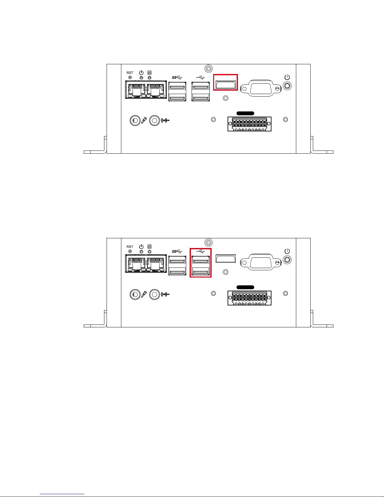
2.2.2.4 VGA
Onboard VGA Port supports auxiliary channel mode. The connection supports
up to 1920 x 1440 resolution at 60Hz.
VGAHDMI
LAN 1 LAN 2
Isolated
DIO
20
©Vecow SPC-4000 User Manual
GETTING TO KNOW YOUR SPC-4000
2.2.2.5 HDMI
Onboard HDMI Port supports DDC channel mode. The connection supports up
to 3840 x 2160 resolution at 30Hz.
VGAHDMI
LAN 1 LAN 2
Isolated
DIO
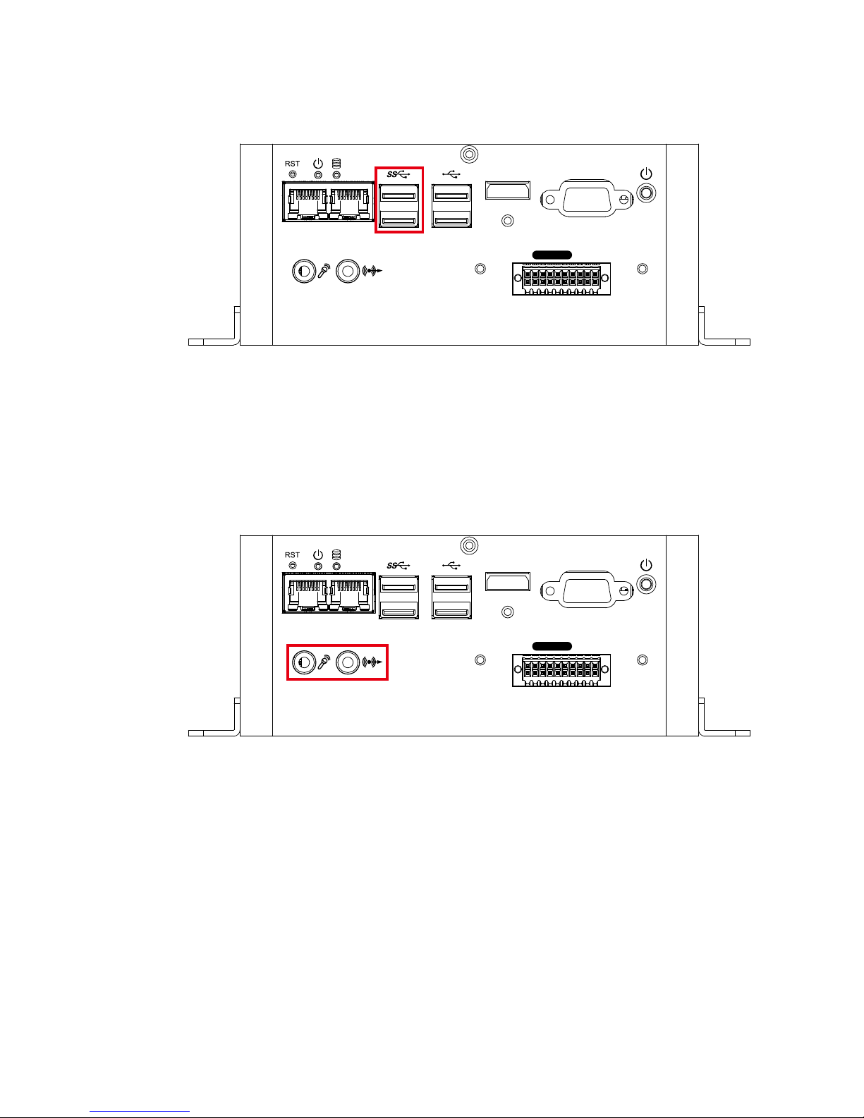
2.2.2.6 USB 2.0
There are 2 USB 2.0 connections available supporting up to 480MB per second
data rate.
VGAHDMI
LAN 1 LAN 2
Isolated
DIO
21
©Vecow SPC-4000 User Manual
GETTING TO KNOW YOUR SPC-4000
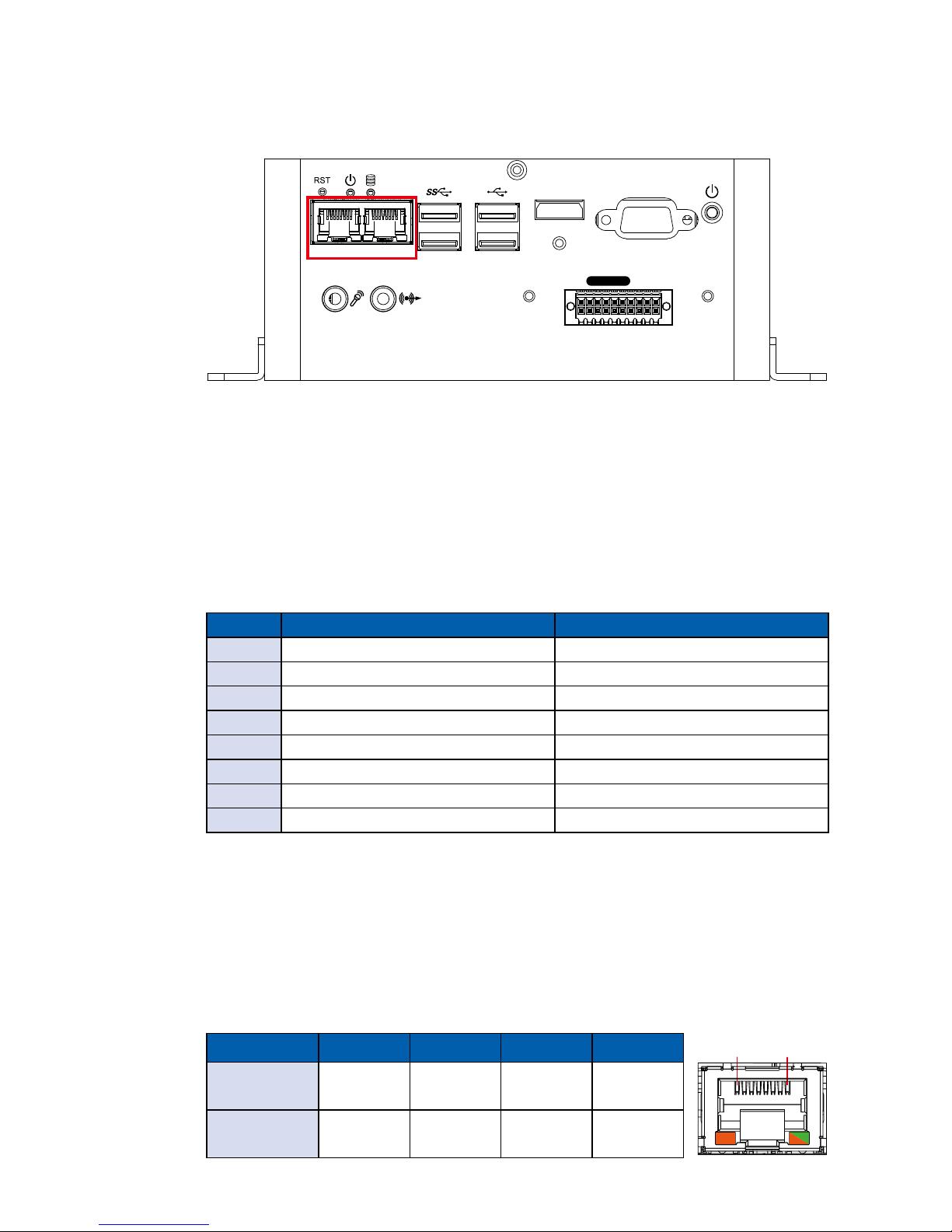
2.2.2.7 USB 3.0
There are 2 USB 3.0 connections available supporting up to 5GB per second
data rate. It is also compliant with the requirements of Super Speed (SS), High
Speed (HS), Full Speed (FS) and Low Speed (LS).
VGAHDMI
LAN 1 LAN 2
Isolated
DIO
2.2.2.8 Audio Jack
There are 2 audio connectors, Mic-in (Left) and Line-out (Right), in the front
side of SPC-4020. Onboard Realtek ALC892 audio codec supports 5.1
channel HD audio and fully complies with Intel® High Denition Audio (Azalia)
specifications. To utilize the audio function in Windows platform, you need to
install corresponding drivers for Realtek ALC892 codec.
VGAHDMI
LAN 1 LAN 2
Isolated
DIO
22
©Vecow SPC-4000 User Manual
GETTING TO KNOW YOUR SPC-4000
2.2.2.9 10/100/1000 Mbps Ethernet Port
There are 2 8-pin RJ-45 jacks supporting 10/100/1000 Mbps Ethernet
connections in the front side of SPC-4020/SPC-4020A. LAN 1 (Left side) and
LAN 2 (Right side) are powered by Intel® I210 Ethernet engine with IEEE 1588,
The Precision Time Protocol (PTP) function. When both LAN 1 and LAN 2 work
in normal status, basic iAMT function is enabled.
Using suitable RJ-45 cable, you can connect SPC-4020/SPC-4020A system to a
computer, or to any other devices with Ethernet connection, for example, a hub
or a switch. Moreover, both of LAN 1 and LAN 2 support Wake on LAN and Preboot functions. The pinouts of LAN 1 and LAN 2 are listed as follows :
Pin No. 10/100 Mbps 1000Mbps
1 E_TX+ MDI0_P
2 E_TX- MDI0_N
3 E_RX+ MDI1_P
4 ----- MDI2_P
5 ----- MDI2_N
6 E_RX- MDI1_N
7 ----- MDI3_P
8 ----- MDI3_N
VGAHDMI
LAN 1 LAN 2
Isolated
DIO
Each LAN port is supported by standard RJ-45 connector with LED indicators to
present Active/Link/Speed status of the connection.
The LED indicator on the right bottom corner lightens in solid green when the
cable is properly connected to a 100Mbps Ethernet network. The LED indicator
on the right bottom corner lightens in solid orange when the cable is properly
connected to a 1000Mbps Ethernet network. The left LED will keep twinkling/o
when Ethernet data packets are being transmitted/received.
LED Location LED Color 10Mbps 100Mbps 1000Mbps
Right
Green/
Orange
O
Solid
Green
Solid
Orange
Left Yellow
Twinkling
Yellow
Twinkling
Yellow
Twinkling
Yellow
1 8
23
©Vecow SPC-4000 User Manual
GETTING TO KNOW YOUR SPC-4000
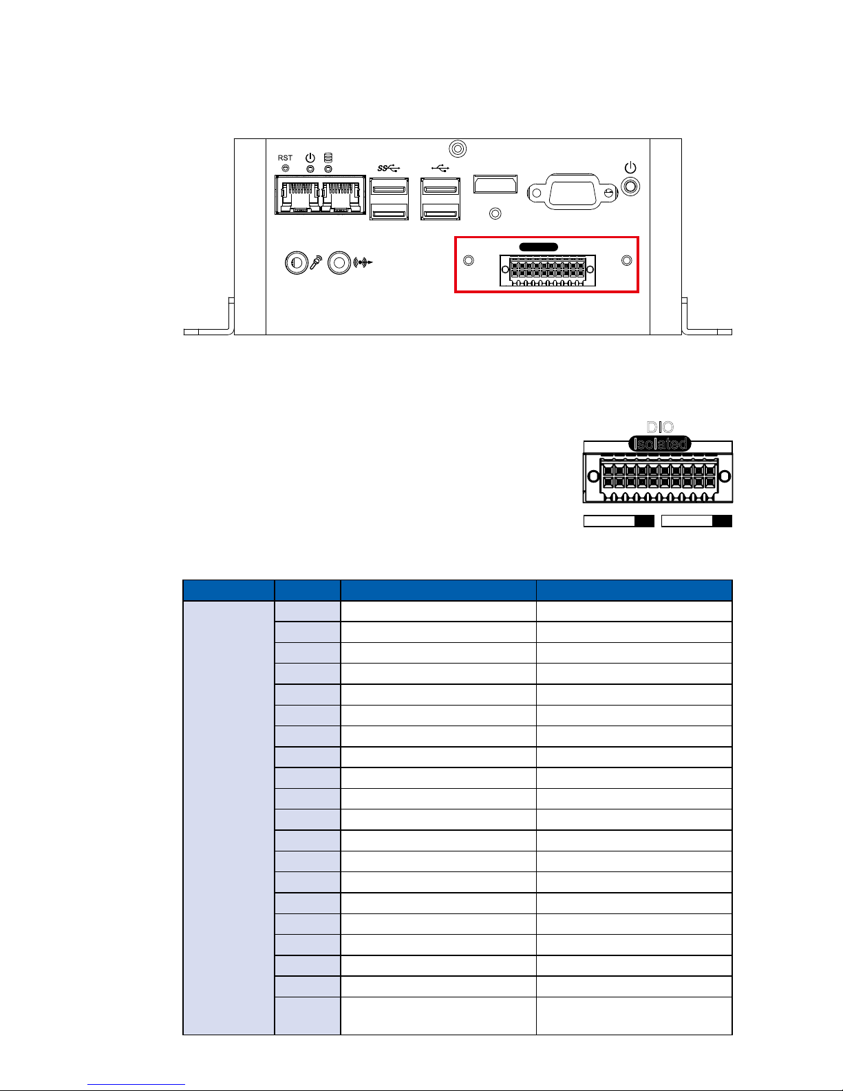
2.2.1.10 Isolated DIO
There is a 16-bit (8-bit DI, 8-bit DO) connectors in the front side. DI and DO
support NPN (sink) and PNP (Source) modes. Each DI pin is equipped with
a photocoupler for isolated protection. Each DO pin is equipped with isolator
function, DO Safety-Related Certications :
• 4242-VPK Basic Isolation per DIN V VDE V 0884-10
and DIN EN 61010-1
• 3-KVRMS Isolation for 1 minute per UL 1577
• CSA Component Acceptance Notice 5A, IEC 60950-1
and IEC 61010-1 End Equipment Standards
• GB4943.1-2011 CQC Certified
VGAHDMI
LAN 1 LAN 2
Isolated
DIO
DIO Connectors pin out :
DIO Pin No. Denition Function
DIO
1 INPUT 0 SIO_GPI80
2 INPUT 1 SIO_GPI81
3 INPUT 2 SIO_GPI82
4 INPUT 3 SIO_GPI83
5 INPUT 4 SIO_GPI84
6 INPUT 5 SIO_GPI85
7 INPUT 6 SIO_GPI86
8 INPUT 7 SIO_GPI87
9 DI_COM -
10 DIO_GND -
11 OUTPUT 0 SIO_GPO70
12 OUTPUT 1 SIO_GPO71
13 OUTPUT 2 SIO_GPO72
14 OUTPUT 3 SIO_GPO73
15 OUTPUT 4 SIO_GPO74
16 OUTPUT 5 SIO_GPO75
17 OUTPUT 6 SIO_GPO76
18 OUTPUT 7 SIO_GPO77
19 DIO_GND -
20
External 6-40VDC (NPN)
External 6-48VDC (PNP)
-
Isolated
DIO
D IPIN 1 ~ 8 DOPIN 11 ~ 18
20 11
10 1
 Loading...