

Page 1

USER
Manual
USER
Manual
1.1.0 Edition 20161201
MTC-4021
21.5” Fanless Multi-Touch Computer, 6 GbE LAN with 4 PoE+,
2 SIM, 4 USB, Intel
®
Core™ i7/i5/i3 Processor (Broadwell-U)
Page 2
ii
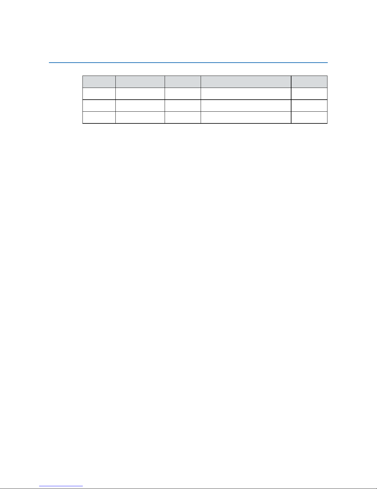
Version Date Page Description Remark
0.1 12/18/2015 All Preliminary Release
1.0 03/23/2016 All Ofcial Release
1.1 12/01/2016
45-46 Update
Record of Revision
Page 3

iii
This manual is released by Vecow Co., Ltd. for reference purpose only. All
product offerings and specications are subject to change without prior notice. It
does not represent commitment of Vecow Co., Ltd. Vecow shall not be liable for
direct, indirect, special, incidental, or consequential damages arising out of the
use of the product or documentation, nor for any infringements upon the rights
of third parties, which may result from such use.
This equipment has been tested and found to comply with the limits for a Class
A digital device, pursuant to part 15 of the FCC Rules. These limits are designed
to provide reasonable protection against harmful interference when the
equipment is operated in a commercial environment. This equipment generates,
uses, and can radiate radio frequency energy and, if not installed and used in
accordance with the instruction manual, may cause harmful interference to radio
communications. Operation of this equipment in a residential area is likely to
cause harmful interference in which case the user will be required to correct the
interference at his own expense.
FCC
The product (s) described in this manual complies with all applicable European
Union (CE) directives if it has a CE marking. For computer systems to
remain CE compliant, only CE-compliant parts may be used. Maintaining CE
compliance also requires proper cable and cabling techniques.
CE
This document contains proprietary information protected by copyright. No part
of this publication may be reproduced in any form or by any means, electric,
photocopying, recording or otherwise, without prior written authorization
by Vecow Co., Ltd. The rights of all the brand names, product names and
trademarks belong to their respective owners.
Declaimer
Declaration of Conformity
Copyright and Trademarks
Page 4
iv
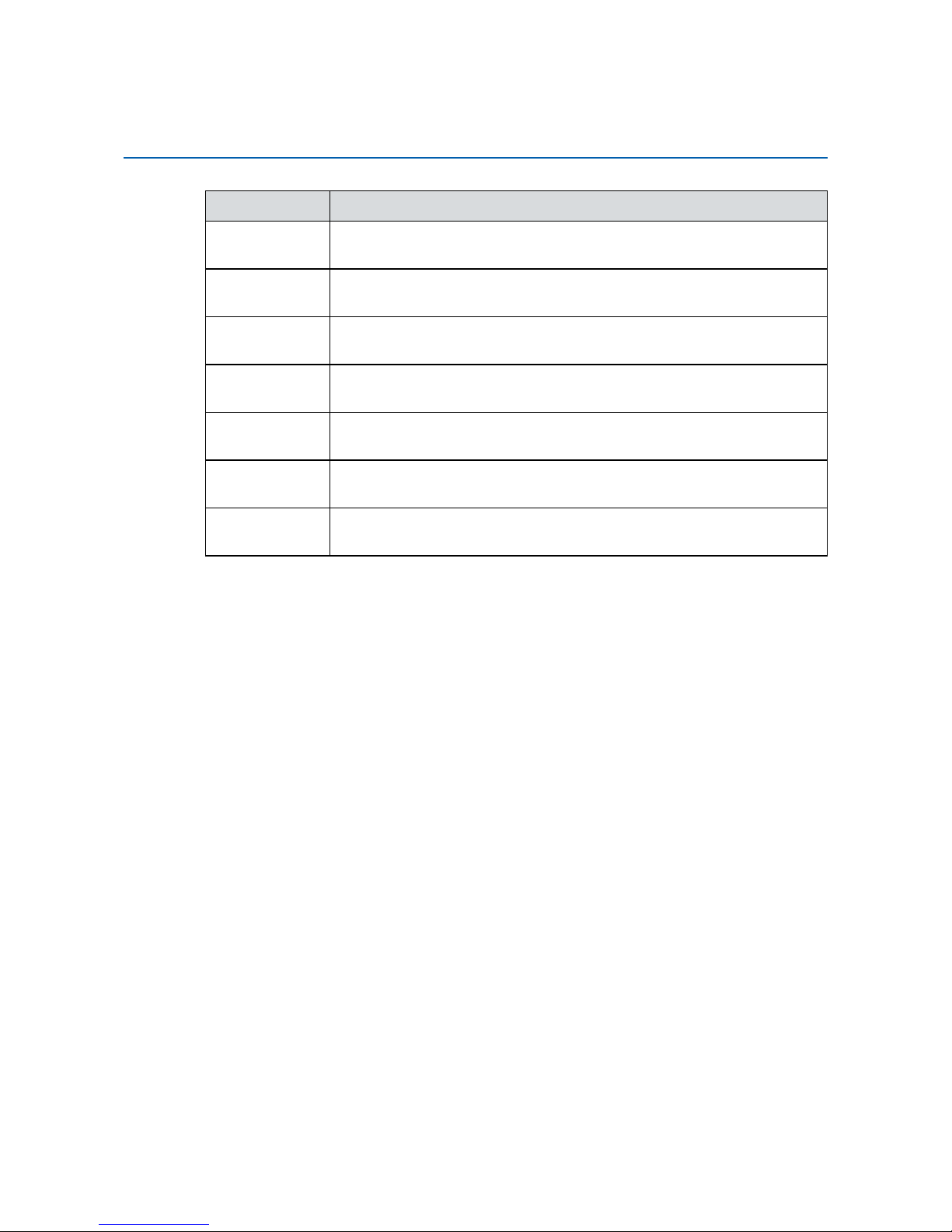
Part Number Description
MTC-4021PoE650U
21.5" Fanless Multi-Touch Computer, 6 GbE LAN with 4 PoE+,
2 SIM, 4 COM, 4 USB, Onboard Intel® Core™ i7-5650U
MTC-4021PoE350U
21.5" Fanless Multi-Touch Computer, 6 GbE LAN with 4 PoE
+
,
2 SIM, 4 COM, 4 USB, Onboard Intel® Core™ i5-5350U
MTC-4021PoE010U
21.5" Fanless Multi-Touch Computer, 6 GbE LAN with 4 PoE
+
,
2 SIM, 4 COM, 4 USB, Onboard Intel
®
Core™ i3-5010U
MTC-40212G650U
21.5" Fanless Multi-Touch Computer, 2 GbE LAN, 2 SIM, 4 COM,
4 USB, Onboard Intel
®
Core™ i7-5650U
MTC-40212G350U
21.5" Fanless Multi-Touch Computer, 2 GbE LAN, 2 SIM, 4 COM,
4 USB, Onboard Intel
®
Core™ i5-5350U
MTC-40212G010U
21.5" Fanless Multi-Touch Computer, 2 GbE LAN, 2 SIM, 4 COM,
4 USB, Onboard Intel
®
Core™ i3-5010U
MTC-4021P 21.5" Fanless Multi-Touch Computer with 5th Gen Intel
®
Core™
i7/ i5/ i3 Processor (Broadwell-U), built with IP65 Front Bezel
Order Information
Page 5
v
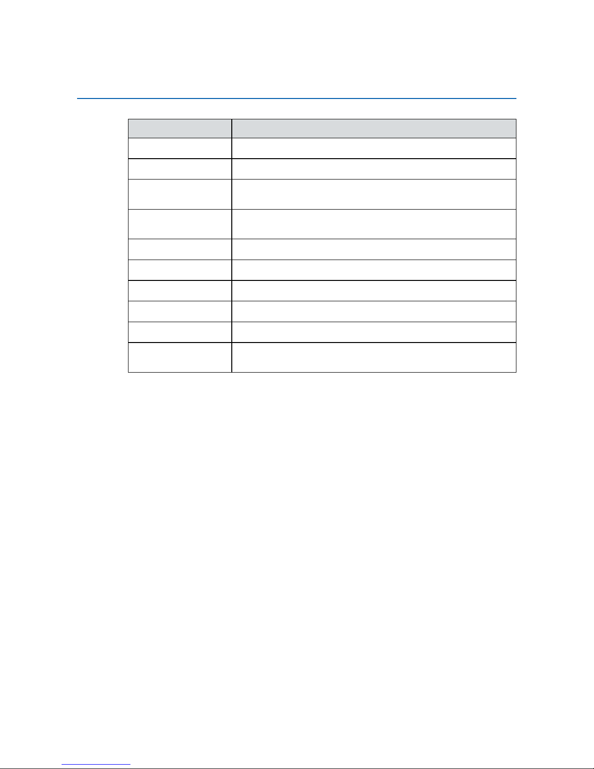
Part Number Description
DDR3L8G
Certied DDR3L-1600 8G RAM
DDR3L4G
Certied DDR3L-1600 4G RAM
PWA-120W 120W, 24V, 90VAC to 264VAC Power Adapter with 3-pin
Terminal Block
PWA-160W-WT 160W, 24V, 85VAC to 264VAC Power Adapter with 3-pin
Terminal Block, Wide Temperature -30°C to +70°C
Panel-Mount
Panel Mount Kit
VESA Stand
VESA Table Stand
3G Module
Mini PCIe 3G/GPS Module with Antenna
4G Module
Mini PCIe 4G/GPS Module with Antenna
WiFi Module
Mini PCIe WiFi Module with Antenna
WiFi & Bluetooth
Module
Mini PCIe WiFi & Bluetooth Module with Antenna
Optional Accessories
Page 6

vi
Table of Contents
CHAPTER 1 GENERAL INTRODUCTION 1
1.1 Overview 1
1.2 Features 1
1.3 Product Specication 2
1.3.1 Specications of MTC-4021-PoE 2
1.3.2 Specications of MTC-4021-2G 4
1.4 Supported CPU List 6
1.5 Mechanical Dimensions 7
1.5.1 Dimensions of MTC-4021-PoE 7
1.5.2 Dimensions of MTC-4021-2G 7
CHAPTER 2 GETTING TO KNOW YOUR MTC-4021 8
2.1 Packing List 8
2.2 I/O Functions 8
2.3 Main Board Expansion Connectors 17
2.4 Main Board Jumper Settings 29
CHAPTER 3 SYSTEM SETUP 34
3.1 How to Open Your MTC-4021 34
3.1.1 MTC-4021 34
3.1.2 MTC-4021 with IP65 36
3.2 Installing DDR3L SO-DIMM Modules 38
3.3 Installing Mini PCIe Cards 39
3.4 Installing Antenna Cable 40
3.5 Installing CFast Card and SIM Card 42
3.6 Installing SSD/ HDD 43
3.7 Mounting MTC-4021 45
Page 7

vii
CHAPTER 4 BIOS AND DRIVER 47
4.1 BIOS Settings 47
4.2 Main Menu 48
4.3 Advanced Function 49
4.4 Chipset Function 57
4.5 Boot Function 58
4.6 Save & Exit 59
APPENDIX A : GPIO and WDT Functions 60
Page 8

1
GENERAL INTRODUCTION
1
GENERAL INTRODUCTION
MTC-4021 Series Fanless Multi-Touch Computer is a 21.5 inch all-in-one fanless
Multi-Touch Computer for Internet of Thing (IoT) and/ or Industry 4.0 applications
with excellent performance and trusted reliability. Powered by 5th generation
Intel® Core™ i7/ i5/ i3 U-Series SoC (Broadwell-U) engine, dual DDR3L 1333/
1600 MHz SO-DIMMs, up to 16GB memory. Advanced Intel
®
HD Graphics 6000
supports 1080p Full HD displays, onboard DVI-D and DisplayPort display interface
delivers up to 20% enhanced graphics performance than former generation.
Full HD LCD panel with LED backlight, Projected Capacitive 10-point Multi-Touch
Screen with 7H Anti-Scratch Surface, Touchscreen works with gloves, internal
2.5” SSD/ HDD bracket, 6 Gigabit LAN ports with 4 IEEE 802.3at PoE
+
ports, 2
Mini PCIe sockets for PCIe/ USB/ External SIM Card/ mSATA, 2 External SIM
Card sockets support 3G/ 4G/ LTE/ WiFi/ GPRS/ UMTS, 1 External CFast socket,
2 USB 3.0, 2 USB 2.0, 4 COM RS-232/ 422/ 485, 6V to 36V wide range power
input with up to 80V smart surge protection, all-in-one fanless design, 0°C to 50°C
operating temperature, optional supports sunlight readable features and IP65
front panel protection, MTC-4021 is ready to customize for your requirements.
Vecow MTC-4021 Series Fanless Multi-Touch Computer integrates outstanding
system performance, considerate user experience, smart protection functions
and trusted reliability for Smart Manufacturing, Medical, Industrial Automation,
Infotainment, Self-service, Smart Transportation and any IoT/ Industry 4.0
applications.
1.1 Overview
1.2 Features
• 21.5” 16 : 9 Full HD (1920 x 1080) LCD Panel with LED Backlight
• Projected Capacitive 10-point Multi-Touch Screen with 7H Anti-Scratch Surface
• Fanless, 5th generation Intel
®
Core™ i7/ i5/ i3 U-Series Processor (Broadwell-U)
• 6V to 36V DC-in, 80V Surge Protection
• 6 Gigabit LAN with 4 IEEE 802.3at PoE
+
• 2 External SIM Socket support 3G/ 4G/ LTE/ WiFi/ GPRS/ UMTS
• External CFast, 4 COM RS-232/ 422/ 485, 2 USB 3.0, 2 USB 2.0
• Touchscreen works with gloves
• Sunlight Readable (Optional)
• IP65 Front Panel Protection (Optional)
Page 9
2
GENERAL INTRODUCTION
©Vecow MTC-4021 User Manual
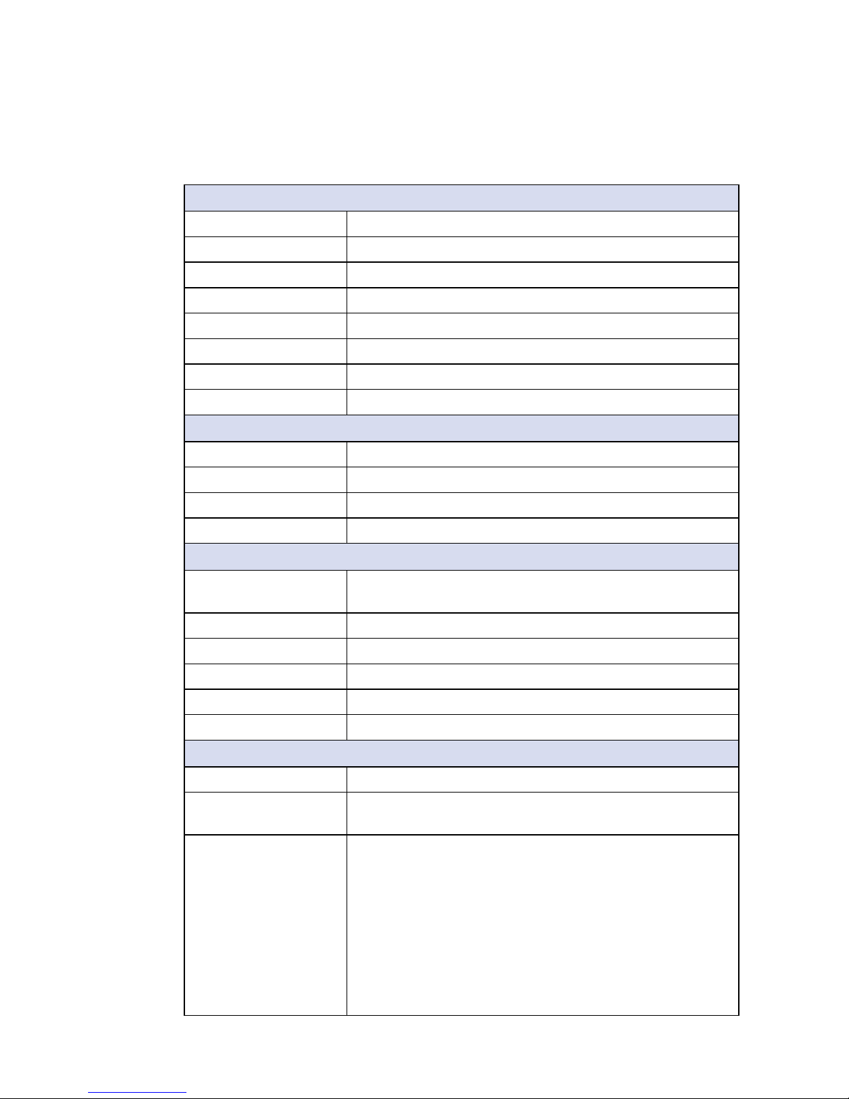
1.3 Product Specication
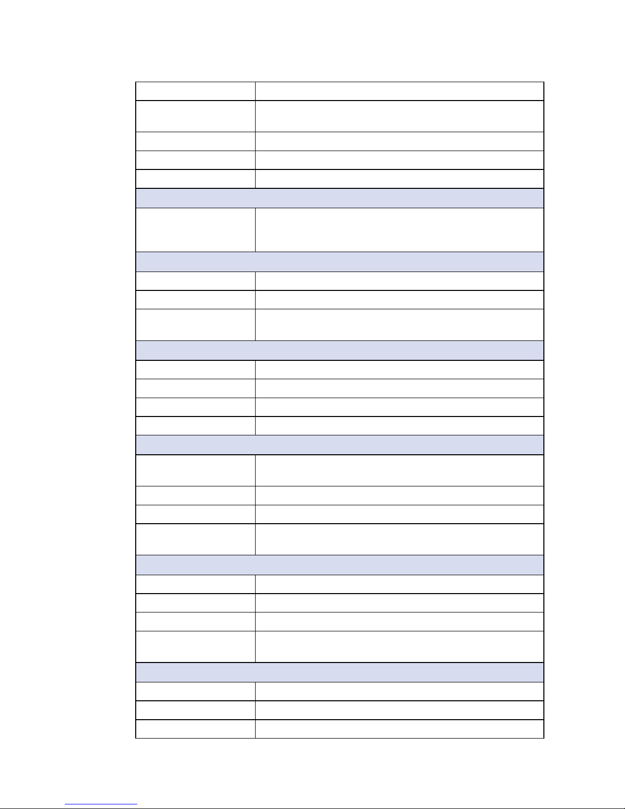
1.3.1 Specications of MTC-4021-PoE
Panel
Panel Type TFT LCD
Active Area 21.5” (16 : 9)
Max Resolution 1920 x 1080 (Full HD)
Display Color 16.7M (RGB 8-bit)
Backlight LED Backlight
Brightness (cd/m2) 250 (Optional, up to 1200)
Viewing Angle 178°/178° (H/V)
Contrast Ratio 3000 : 1
Touch Screen
Touch Screen Type 10-point Projected Capacitive
Transparency 85%
Surface Hardness 7H Surface Hardness
Control Interface USB Interface
System
Processor Intel® Core™ i7-5650U/ i5-5350U/ i3-5010U Processor
(Broadwell-U)
Chipset Intel
®
SoC
Memory 2 DDR3L 1333/ 1600 MHz SO-DIMM, up to 16GB
Graphics Intel
®
HD Graphics 6000
Audio Realtek ALC892, 5.1 Channel HD Audio
OS Support Windows 8, Windows 7, Linux
I/O Interface
Serial 4 COM RS-232/ 422/ 485
USB • 2 External USB 3.0
• 2 External USB 2.0
LAN • LAN 1 : Intel
®
I218 Gigabit LAN supports iAMT
• LAN 2 : Intel® I210 Gigabit LAN
• LAN 3 : Intel® I210 Gigabit LAN supports IEEE 802.3at
PoE
+
• LAN 4 : Intel® I210 Gigabit LAN supports IEEE 802.3at
PoE
+
• LAN 5 : Intel® I210 Gigabit LAN supports IEEE 802.3at
PoE
+
• LAN 6 : Intel® I210 Gigabit LAN supports IEEE 802.3at
PoE
+
=
>
Page 10
3
GENERAL INTRODUCTION
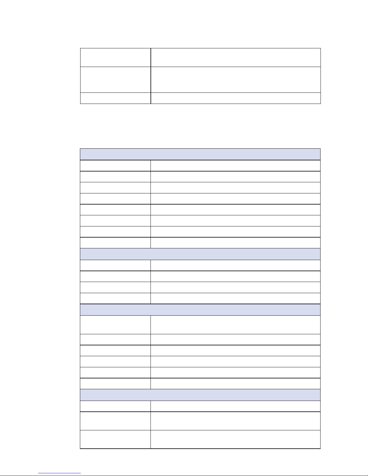
Audio 1 Mic-in, 1 Line-out
Display • DVI-D : Up to 1920 x 1080 @ 60Hz
• DisplayPort : Up to 3840 x 2160 @ 60Hz
LED Power, HDD
CFast 1 External CFast Socket, Push-in/ Push-out Ejector
SIM Card 2 External SIM Card Socket
Expansion
Mini PCIe 2 Mini PCIe Socket :
• 1 Mini PCIe for PCIe/ USB/ External SIM Card
• 1 Mini PCIe for PCIe/ USB/ External SIM Card/ mSATA
Storage
SATA 1 SATA III (6Gbps)
mSATA 1 SATA III (Mini PCIe Type, 6Gbps)
Storage Device • 1 CFast Socket, Push-in/ Push-out Ejector
• 1 Internal SSD/ HDD Bracket
Power
Power Input 6V to 36V, DC-in
Power Interface 3-pin Terminal Block : V+, V-, Frame Ground
Power Adapter AC to DC 120W Power Adapter (Optional)
Surge Protection Up to 80V/1ms Transient Power
Others
TPM Optional Inneon SLB9665 supports TPM 2.0, LPC
Interface
Watchdog Timer Reset : 1 to 255 sec./min. per step
Smart Management Wake on LAN, PXE supported
HW Monitor Monitoring temperature, voltages. Auto throttling control
when CPU overheats.
Mechanical
Dimension (W x L x H) 537.6mm x 329.06mm x 53.1mm (21.2” x 13” x 2.1”)
Weight 5.8 kg (12.8 lb)
Front Panel Protection IP65 Compliant (Optional)
Mounting • VESA Mount (75 x 75mm, 100 x 100mm)
• Panel Mount
Environment
Operating Temperature 0°C to 50°C (32°F to 122°F)
Storage Temperature -20°C to 60°C (-4°F to 140°F)
Humidity 10% to 90% Humidity, non-condensing
Page 11
4
GENERAL INTRODUCTION
©Vecow MTC-4021 User Manual
Shock • IEC 60068-2-27
• 20G, Half-sine, 11ms
Vibration • IEC 60068-2-64
• Non-operation : 10Hz to 200Hz, 1.5Grms, X, Y, Z,
30 mins each Axis
EMC CE, FCC
1.3.2 Specications of MTC-4021-2G
Panel
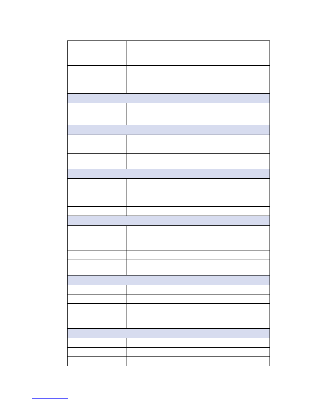
Panel Type TFT LCD
Active Area 21.5” (16 : 9)
Max Resolution 1920 x 1080 (Full HD)
Display Color 16.7M (RGB 8-bit)
Backlight LED Backlight
Brightness (cd/m2) 250 (Optional, up to 1200)
Viewing Angle 178°/178° (H/V)
Contrast Ratio 3000 : 1
Touch Screen
Touch Screen Type 10-point Projected Capacitive
Transparency 85%
Surface Hardness 7H Surface Hardness
Control Interface USB Interface
System
Processor Intel® Core™ i7-5650U/ i5-5350U/ i3-5010U Processor
(Broadwell-U)
Chipset Intel
®
SoC
Memory 2 DDR3L 1333/ 1600 MHz SO-DIMM, up to 16GB
Graphics Intel
®
HD Graphics 6000
Audio Realtek ALC892, 5.1 Channel HD Audio
OS Support Windows 8, Windows 7, Linux
I/O Interface
Serial 4 COM RS-232/ 422/ 485
USB • 2 External USB 3.0
• 2 External USB 2.0
LAN • LAN 1 : Intel
®
I218 Gigabit LAN supports iAMT
• LAN 2 : Intel® I210 Gigabit LAN
=
>
Page 12
5
GENERAL INTRODUCTION
Audio 1 Mic-in, 1 Line-out
Display • DVI-D : Up to 1920 x 1080 @ 60Hz
• DisplayPort : Up to 3840 x 2160 @ 60Hz
LED Power, HDD
CFast 1 External CFast Socket, Push-in/ Push-out Ejector
SIM Card 2 External SIM Card Socket
Expansion
Mini PCIe 2 Mini PCIe Socket :
• 1 Mini PCIe for PCIe/ USB/ External SIM Card
• 1 Mini PCIe for PCIe/ USB/ External SIM Card/ mSATA
Storage
SATA 1 SATA III (6Gbps)
mSATA 1 SATA III (Mini PCIe Type, 6Gbps)
Storage Device • 1 CFast Socket, Push-in/ Push-out Ejector
• 1 Internal SSD/ HDD Bracket
Power
Power Input 6V to 36V, DC-in
Power Interface 3-pin Terminal Block : V+, V-, Frame Ground
Power Adapter AC to DC 120W Power Adapter (Optional)
Surge Protection Up to 80V/1ms Transient Power
Others
TPM Optional Inneon SLB9665 supports TPM 2.0, LPC
Interface
Watchdog Timer Reset : 1 to 255 sec./min. per step
Smart Management Wake on LAN, PXE supported
HW Monitor Monitoring temperature, voltages. Auto throttling control
when CPU overheats.
Mechanical
Dimension (W x L x H) 537.6mm x 329.06mm x 53.1mm (21.2” x 13” x 2.1”)
Weight 5.8 kg (12.8 lb)
Front Panel Protection IP65 Compliant (Optional)
Mounting • VESA Mount (75 x 75mm, 100 x 100mm)
• Panel Mount
Environment
Operating Temperature 0°C to 50°C (32°F to 122°F)
Storage Temperature -20°C to 60°C (-4°F to 140°F)
Humidity 10% to 90% Humidity, non-condensing
Page 13
6
GENERAL INTRODUCTION
©Vecow MTC-4021 User Manual
Shock • IEC 60068-2-27
• 20G, Half-sine, 11ms
Vibration • IEC 60068-2-64
• Non-operation : 10Hz to 200Hz, 1.5Grms, X, Y, Z,
30 mins each Axis
EMC CE, FCC
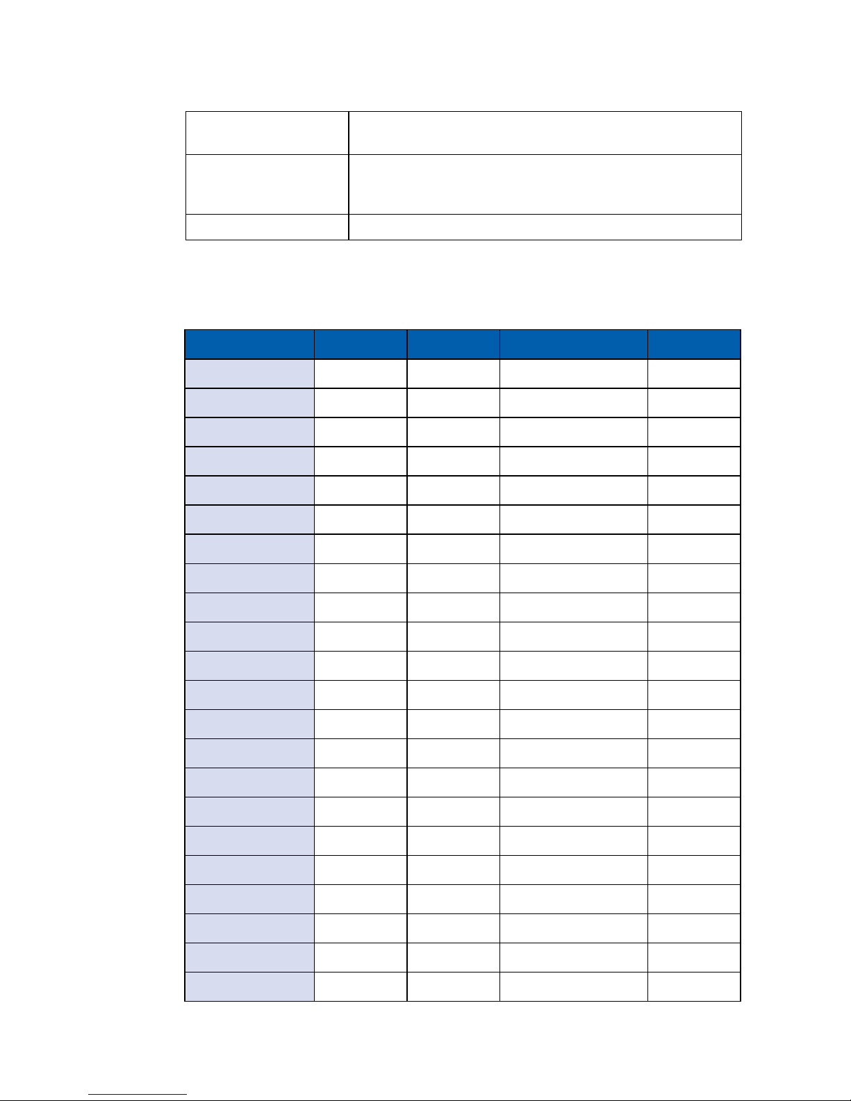
1.4 Supported CPU List
CPU Name TDP Cache Max. Frequency Embedded
i7-5557U 28W 4M Up to 3.40 GHz
i7-5650U 15W 4M Up to 3.20 GHz Ye s
i7-5600U 15W 4M Up to 3.20 GHz
i7-5550U 15W 4M Up to 3.00 GHz
i7-5500U 15W 4M Up to 3.00 GHz
i5-5287U 28W 3M Up to 3.30 GHz
i5-5257U 28W 3M Up to 3.10 GHz
i5-5350U 15W 3M Up to 2.90 GHz Yes
i5-5300U 15W 3M Up to 2.90 GHz
i5-5250U 15W 3M Up to 2.70 GHz
i5-5200U 15W 3M Up to 2.70 GHz
i3-5157U 28W 3M Up to 2.5 0 GHz
i3-5020U 15W 3M Up to 2.20 GHz
i3-5015U 15W 3M Up to 2.10 GHz Ye s
i3-5010U 15W 3M Up to 2.10 GHz
i3-5005U 15W 3M Up to 2.00 GHz
Pentium 3805U 15W 2M Up to 1.90 GHz
Pentium 3825U 15W 2M Up to 1.90 GHz
Celeron 3765U 15W 2M Up to 1.90 GHz
Celeron 3755U 15W 2M Up to 1.70 GHz Yes
Celeron 3215U 15W 2M Up to 1.70 GHz
Celeron 3205U 15W 2M Up to 1.50 GHz
Page 14
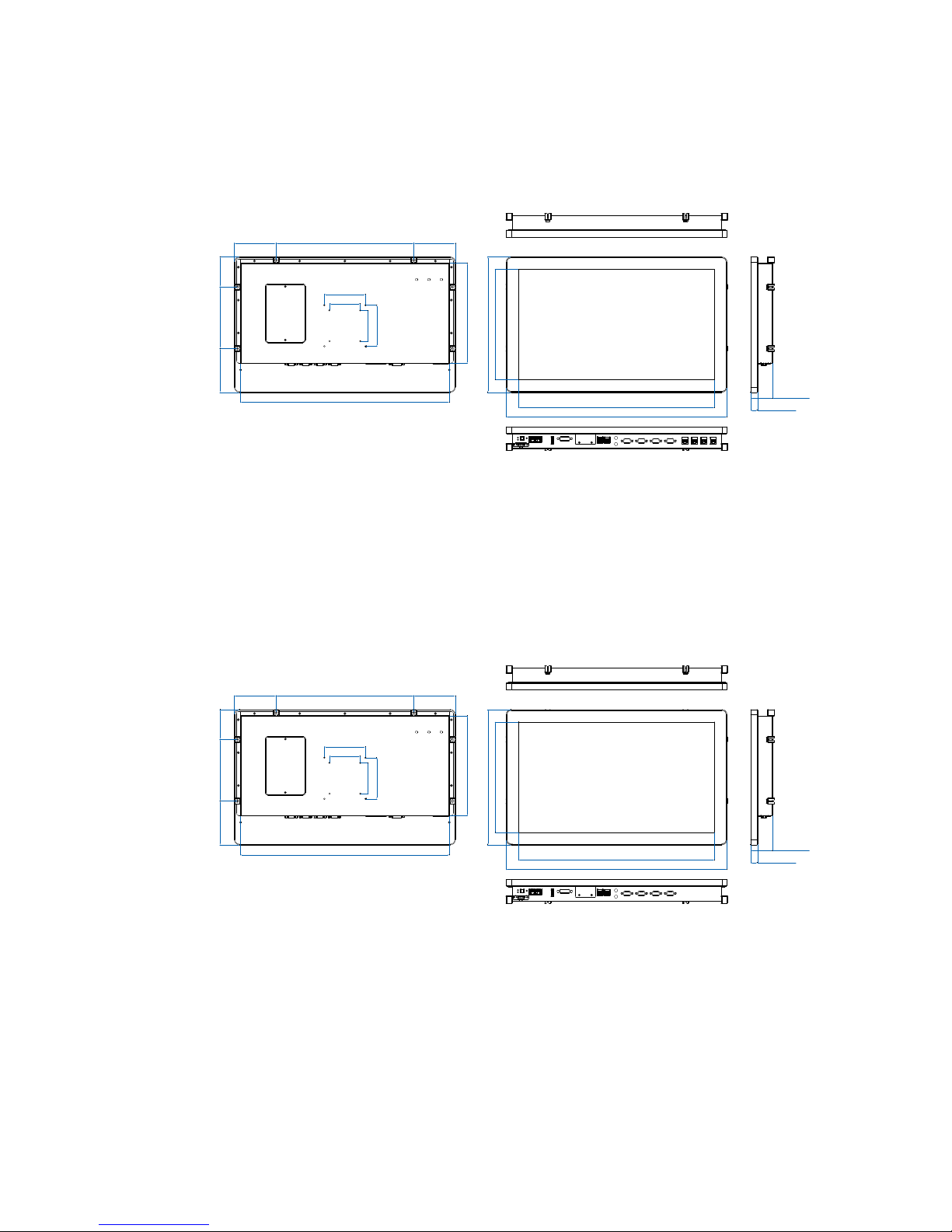
7
GENERAL INTRODUCTION
537.6 (21.2”)
476.6 (18.8")
268.1 (10.6")
329.1 (13")
17.1 (0.7")
53.1 (2.1")
100.0 (3.9")
100.0 (3.9")
150.0 (5.9")106.5 (4.2")
72.6 (2.9")
101.3 (4") 335.0 (13.2") 101.3 (4")
508.0 (20")
243.6 (9.6")
75.0 (3")
75.0 (3")
Unit: mm (inch)
1.5 Mechanical Dimensions
1.5.1 Dimensions of MTC-4021-PoE
1.5.2 Dimensions of MTC-4021-2G
537.6 (21.2”)
476.6 (18.8")
268.1 (10.6")
329.1 (13")
17.1 (0.7")
53.1 (2.1")
100.0 (3.9")
100.0 (3.9")
150.0 (5.9")106.5 (4.2")
72.6 (2.9")
101.3 (4") 335.0 (13.2") 101.3 (4")
508.0 (20")
243.6 (9.6")
75.0 (3")
75.0 (3")
Unit: mm (inch)
Page 15
8
GETTING TO KNOW YOUR MTC-4021©Vecow MTC-4021 User Manual
2
GETTING TO KNOW YOUR MTC-4021
2.1 Packing List
Item Description Qty
1 MTC-4021, 21.5” Fanless Multi-Touch Computer
(According to the conguration you order, the MTC-4021
series may contain SSD/HDD and DDR3L SO-DIMM.
Please do verify these items if possible.)
1
2 Accessory box, which contains
● Vecow Drivers & Utilities DVD
● M2.5x6 screw for Mini PCIe Socket
● 3-pin pluggable terminal block
● M3x6 screw for HDD
1
4
1
4
2.2 I/O Functions
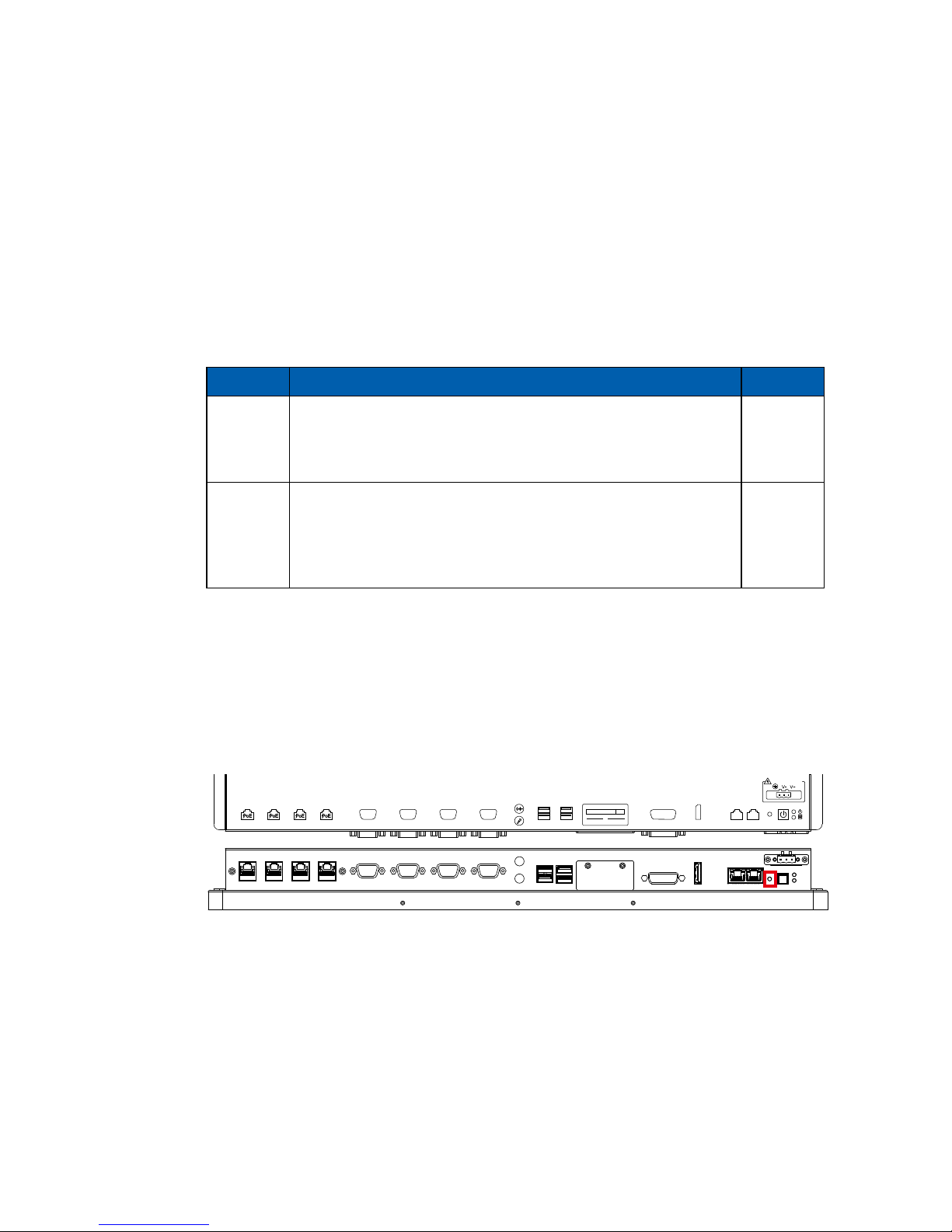
2.2.1 Reset Tact Switch
It is a hardware reset switch to reset the system without power off MTC-4021.
Just press the Reset Switch for a few seconds, then you will enable reset
function.
COM4 COM3 COM2 COM1
CFast
SIM 2 SIM 1
LAN6 LAN5 LAN4 LAN3
RESET
DC-IN 6V~36V
USB3.0USB2.0
DVI-D
LAN2 LAN1DP
Page 16
9
GETTING TO KNOW YOUR MTC-4021
2.2.2 Power Button
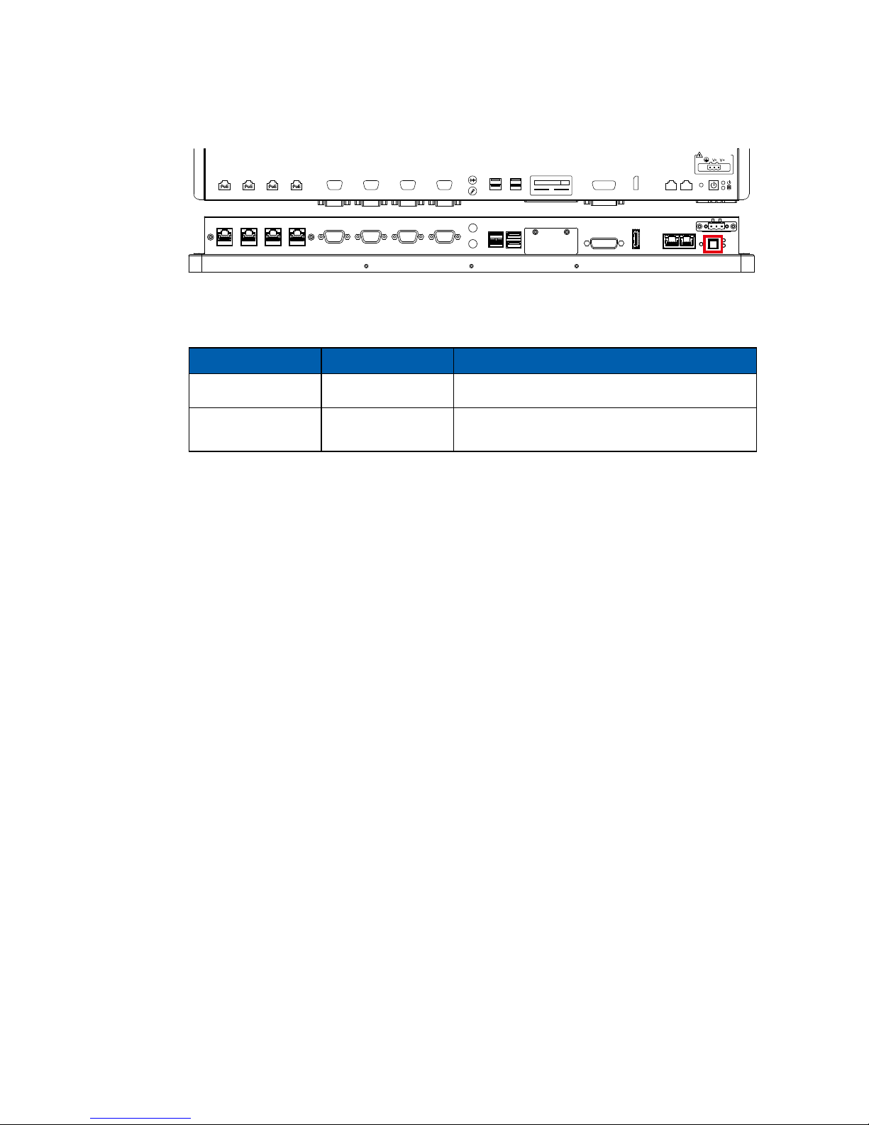
The Power Button is a non-latched switch with LED indication. It indicates power
status: S0, S3 and S5. More details of LED indication are listed as follows:
To power on MTC-4021, press the power button and then the blue LED is
lightened.
To power off MTC-4021, you can either command shutdown by OS operation,
or just simply press the power button.
If system error, you can just press the power button for 4 seconds to shut down
the machine directly.
Please do note that a 4-second interval between each 2 power-on/ power-off
operation is necessary in normal working status. (For example, once turning
off the system, you have to wait for 4 seconds to initiate another power-on
operation).
LED Color Power Status System Status
Solid Blue S0 System working
Solid Orange S3, S5
Suspend to RAM, System off with standby
power
COM4 COM3 COM2 COM1
CFast
SIM 2 SIM 1
LAN6 LAN5 LAN4 LAN3
RESET
DC-IN 6V~36V
USB3.0USB2.0
DVI-D
LAN2 LAN1DP
Page 17
10
GETTING TO KNOW YOUR MTC-4021©Vecow MTC-4021 User Manual
2.2.3 CFast Card
Pin No. Description Pin No. Description
S1 GND PC6 NC
S2 SATA_TXP PC7 GND
S3 SATA_TXN PC8 CFAST_LED
S4 GND PC9 NC
S5 SATA_RXN PC10 NC
S6 SATA_RXP PC11 NC
S7 GND PC12 NC
PC1 GND PC13 +3.3V
PC2 GND PC14 +3.3V
PC3 NC PC15 GND
PC4 NC PC16 GND
PC5 NC PC17 NC
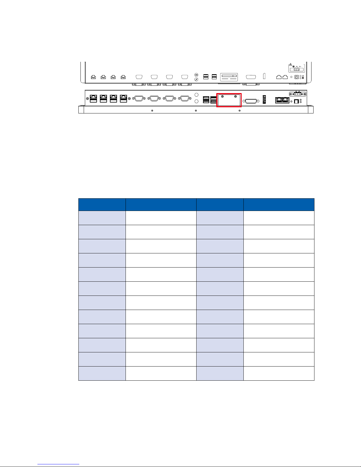
There is a CFast socket supporting Type-I/ Type-II Compact Flash card. It is
implemented by a SATA II Port from Broadwell-U PCH. Be sure to disconnect
the power source and unscrew the CFast socket cover before installing a CFast
card. The MTC-4021 does not support the CFast hot swap and PnP (Plug and
Play) functions. It is necessary to remove power source rst before inserting or
removing the CFast card.
The pinouts of CFast port are listed as follows:
COM4 COM3 COM2 COM1
CFast
SIM 2 SIM 1
LAN6 LAN5 LAN4 LAN3
RESET
DC-IN 6V~36V
USB3.0USB2.0
DVI-D
LAN2 LAN1DP
Page 18
11
GETTING TO KNOW YOUR MTC-4021
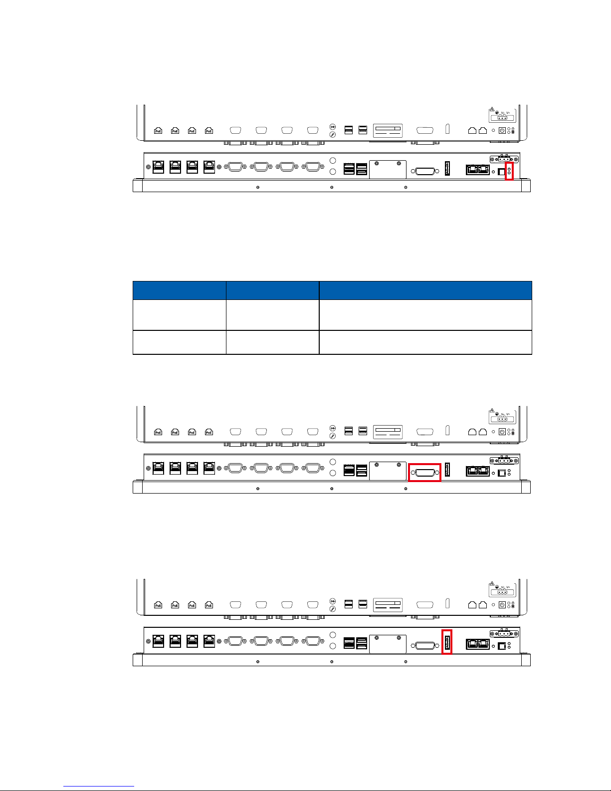
2.2.4 PWR and HDD LED Indicator
LED Color Power Status System Status
Yellow HDD/ CFast
• On/ Off : Storage status, function or not.
• Twinkling : Data transferring.
Green Power System power status (on/ off)
Yellow-HDD LED: A hard disk/ CFast LED. If the LED is on, it indicates that the
system’s storage is functional. If it is off, it indicates that the system’s storage is
not functional. If it is ashing, it indicates data access activities.
Green-Power LED: If the LED is solid green, it indicates that the system is
powered on.
COM4 COM3 COM2 COM1
CFast
SIM 2 SIM 1
LAN6 LAN5 LAN4 LAN3
RESET
DC-IN 6V~36V
USB3.0USB2.0
DVI-D
LAN2 LAN1DP
2.2.5 DVI-D Connector
The DVI-D connector supports DVI display modes. The DVI output mode
supports up to 1920 x 1080 resolutions.
COM4 COM3 COM2 COM1
CFast
SIM 2 SIM 1
LAN6 LAN5 LAN4 LAN3
RESET
DC-IN 6V~36V
USB3.0USB2.0
DVI-D
LAN2 LAN1DP
2.2.6 DisplayPort
Onboard DisplayPort connection supports up to 3840 x 2160 resolutions at 60 Hz.
COM4 COM3 COM2 COM1
CFast
SIM 2 SIM 1
LAN6 LAN5 LAN4 LAN3
RESET
DC-IN 6V~36V
USB3.0USB2.0
DVI-D
LAN2 LAN1DP
Page 19
12
GETTING TO KNOW YOUR MTC-4021©Vecow MTC-4021 User Manual
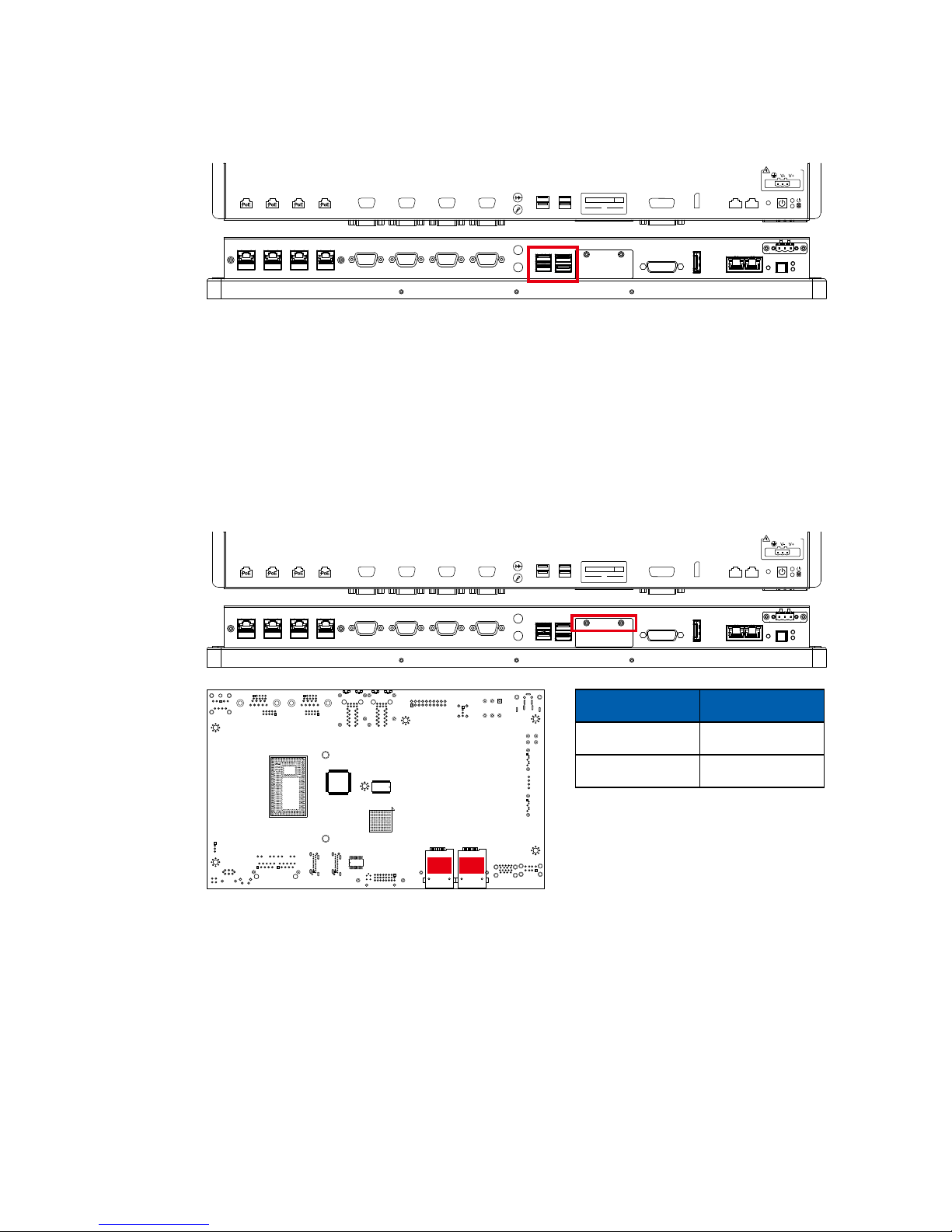
2.2.7 External USB
There are 2 USB 3.0 connections available supporting up to 5GB per second
data rate. It also compliant with the requirements of SuperSpeed (SS), high
speed (HS), full speed (FS) and low speed (LS).
COM4 COM3 COM2 COM1
CFast
SIM 2 SIM 1
LAN6 LAN5 LAN4 LAN3
RESET
DC-IN 6V~36V
USB3.0USB2.0
DVI-D
LAN2 LAN1DP
2.2.8 Mini PCIe & SIM Card Comparison Table
Note:
The SIM card sockets do not support hot-plug. Please make sure to unplug the
system power before inserting the SIM card(s).
CN30 CN31
Mini PCIe SIM
CN18 CN30 (SIM 1)
CN16 CN31 (SIM 2)
COM4 COM3 COM2 COM1
CFast
SIM 2 SIM 1
LAN6 LAN5 LAN4 LAN3
RESET
DC-IN 6V~36V
USB3.0USB2.0
DVI-D
LAN2 LAN1DP
Page 20
13
GETTING TO KNOW YOUR MTC-4021
Pin No. 10/ 100Mbps 1000Mbps
1 E_TX+ MDI0_P
2 E_TX- MDI0_N
3 E_RX+ MDI1_P
4 ---- MDI2_P
5 ----- MDI2_N
6 E_RX- MDI1_N
7 ----- MDI3_P
8 ------ MDI3_N
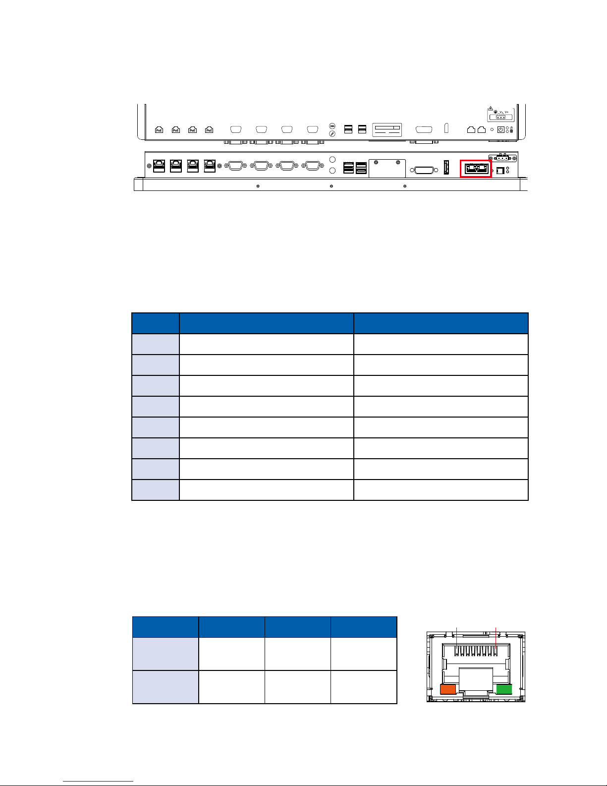
Each LAN port is supported by standard RJ-45 connector with LED indicators to
present Active/ Link/ Speed status of the connection.
The LED indicator on the right bottom corner lightens in solid green when the
cable is properly connected to a 100Mbps Ethernet network; The LED indicator
on the right bottom corner lightens in solid orange when the cable is properly
connected to a 1000Mbps Ethernet network; The left LED will keep twinkling/ off
when Ethernet data packets are being transmitted/ received.
1 8
LED 10Mbps 100Mbps 1000Mbps
Right
Bottom Led
Off
Solid
Green
Solid
Orange
Left
Bottom Led
Twinkling
Yellow
Twinkling
Yellow
Twinkling
Yellow
2.2.9 10/ 100/ 1000 Mbps Ethernet Port
There are 2 8-pin RJ-45 jacks supporting 10/ 100/1000 Mbps Ethernet
connections. LAN 1 is powered by Intel® 218LM Ethernet engine; LAN 2 is
powered by Intel I210 Ethernet engine. When both LAN 1 and LAN 2 work in
normal status, basic iAMT function is enabled. Using suitable RJ-45 cable, you
can connect MTC-4021 system to a computer, or to any other devices with
Ethernet connection, for example, a hub or a switch. Moreover, both of LAN 1
and LAN 2 supports Wake on LAN and Pre-boot functions. The pinouts of LAN
1 and LAN 2 are listed as follows:
COM4 COM3 COM2 COM1
CFast
SIM 2 SIM 1
LAN6 LAN5 LAN4 LAN3
RESET
DC-IN 6V~36V
USB3.0USB2.0
DVI-D
LAN2 LAN1DP
Page 21
14
GETTING TO KNOW YOUR MTC-4021©Vecow MTC-4021 User Manual
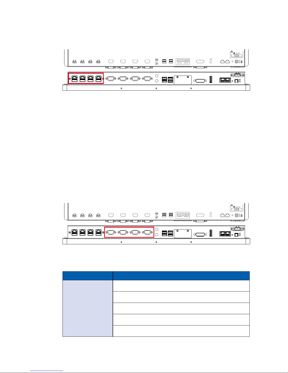
2.2.10 PoE (Power over Ethernet) Ports
There are 4 RJ45 connectors supporting IEEE 802.3at (PoE+) Power
over Ethernet (PoE) connection delivering up to 25.5W/ 48V per port and
1000BASE-T gigabit data signals over standard Ethernet Cat 5/ Cat 6 cable.
Each PoE connection is powered by Intel® I210 Gigabit Ethernet controller and
independent PCI express interface to connect with multi-core processor for
network and data transmit optimization. Only when PoE port starts to supply
power to power devices, the dedicated LED will be lightened.
PS. Suggest to use PoE function when power input is over 11V.
COM4 COM3 COM2 COM1
CFast
SIM 2 SIM 1
LAN6 LAN5 LAN4 LAN3
RESET
DC-IN 6V~36V
USB3.0USB2.0
DVI-D
LAN2 LAN1DP
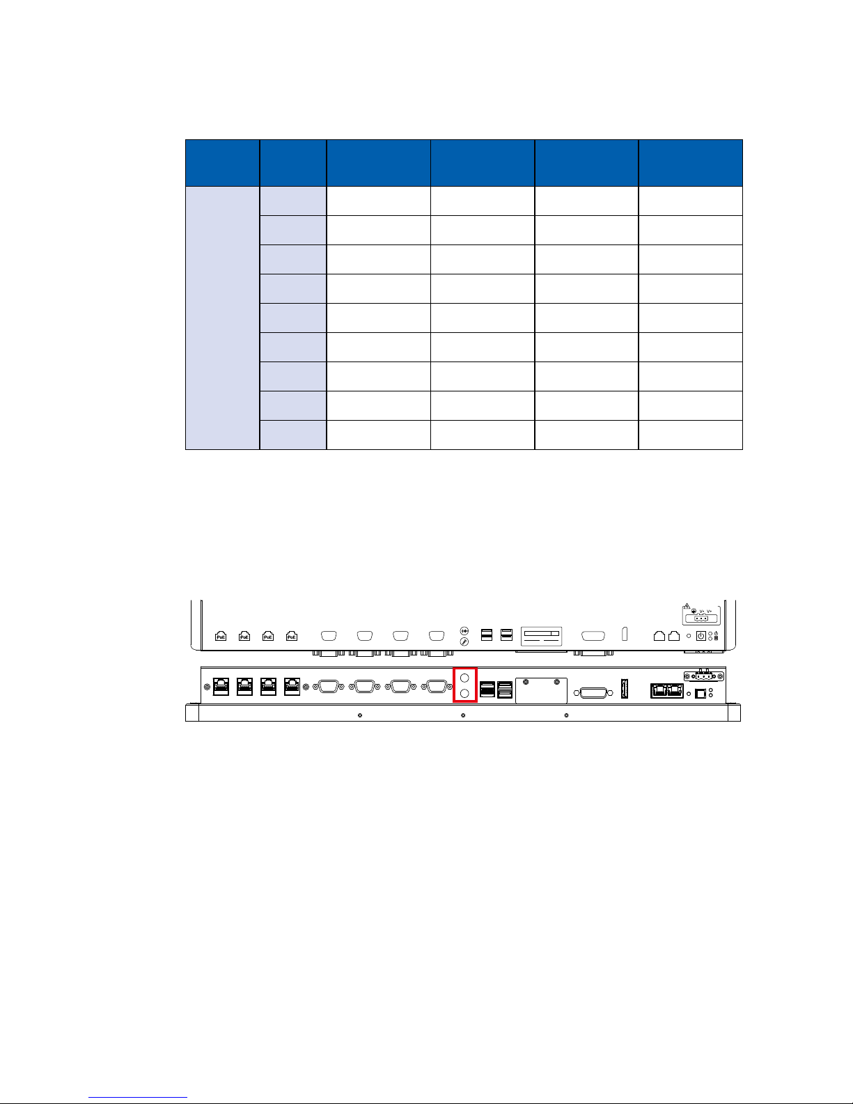
2.2.11 Serial Port COM
Serial port can be configured for RS-232, RS-422, or RS-485 with auto flow
control communication. The default denition is RS-232, if you want to change
to RS-422 or RS-485, you can nd the setting in BIOS.
COM4 COM3 COM2 COM1
CFast
SIM 2 SIM 1
LAN6 LAN5 LAN4 LAN3
RESET
DC-IN 6V~36V
USB3.0USB2.0
DVI-D
LAN2 LAN1DP
BIOS Setting Function
COM 1 (CN7) /
COM 2 (CN8) /
COM 3 (CN11) /
COM 4 (CN12)
RS-232
RS-422 (5-wire)
RS-422 (9-wire)
RS-485
RS-485 w/z auto-ow control
Page 22
15
GETTING TO KNOW YOUR MTC-4021
Serial
Port
Pin No. RS-232 RS-422
(5-wire)
RS-422
(9-wire)
RS-485
(3-wire)
1, 2
3, 4
1 DCD TXD- TXD- DATA-
2 RXD TXD+ TXD+ D ATA+
3 TXD RXD+ RXD+ -----------
4 DTR RXD- RXD- -----------
5 GND GND GND GND
6 DSR ----------- RTS- -----------
7 RTS ----------- RTS+ -----------
8 CTS ----------- CTS+ -----------
9 RI ----------- CTS- -----------
The pin assignments are listed in the table as follow :
2.2.12 Audio Connector
There are 2 audio connectors, Mic-in and Line. Onboard Realtek ALC892
audio codec supports 5.1 channel HD audio and fully complies with Intel® High
Denition Audio (Azalia) specications.
To utilize the audio function in Windows platform, you need to install
corresponding drivers for both Intel Broadwell-U chipset and Realtek ALC892
codec.
COM4 COM3 COM2 COM1
CFast
SIM 2 SIM 1
LAN6 LAN5 LAN4 LAN3
RESET
DC-IN 6V~36V
USB3.0USB2.0
DVI-D
LAN2 LAN1DP
Page 23
16
GETTING TO KNOW YOUR MTC-4021©Vecow MTC-4021 User Manual
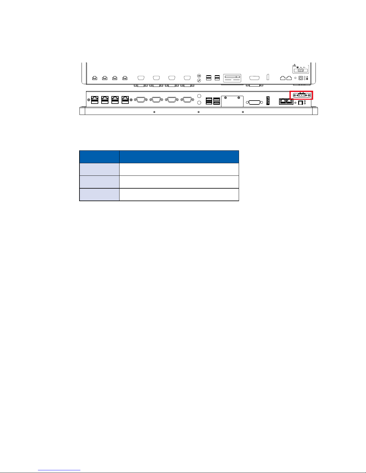
2.2.13 Power Terminal Block
MTC-4021 supports 6V to 36V DC power input by terminal block. In normal
power operation, power LED lightens in solid green. MTC-4021 supports up to
80V surge protection.
COM4 COM3 COM2 COM1
CFast
SIM 2 SIM 1
LAN6 LAN5 LAN4 LAN3
RESET
DC-IN 6V~36V
USB3.0USB2.0
DVI-D
LAN2 LAN1DP
Pin No. Denition
1 V+
2 V-
3 Earth GND
Page 24
17
GETTING TO KNOW YOUR MTC-4021
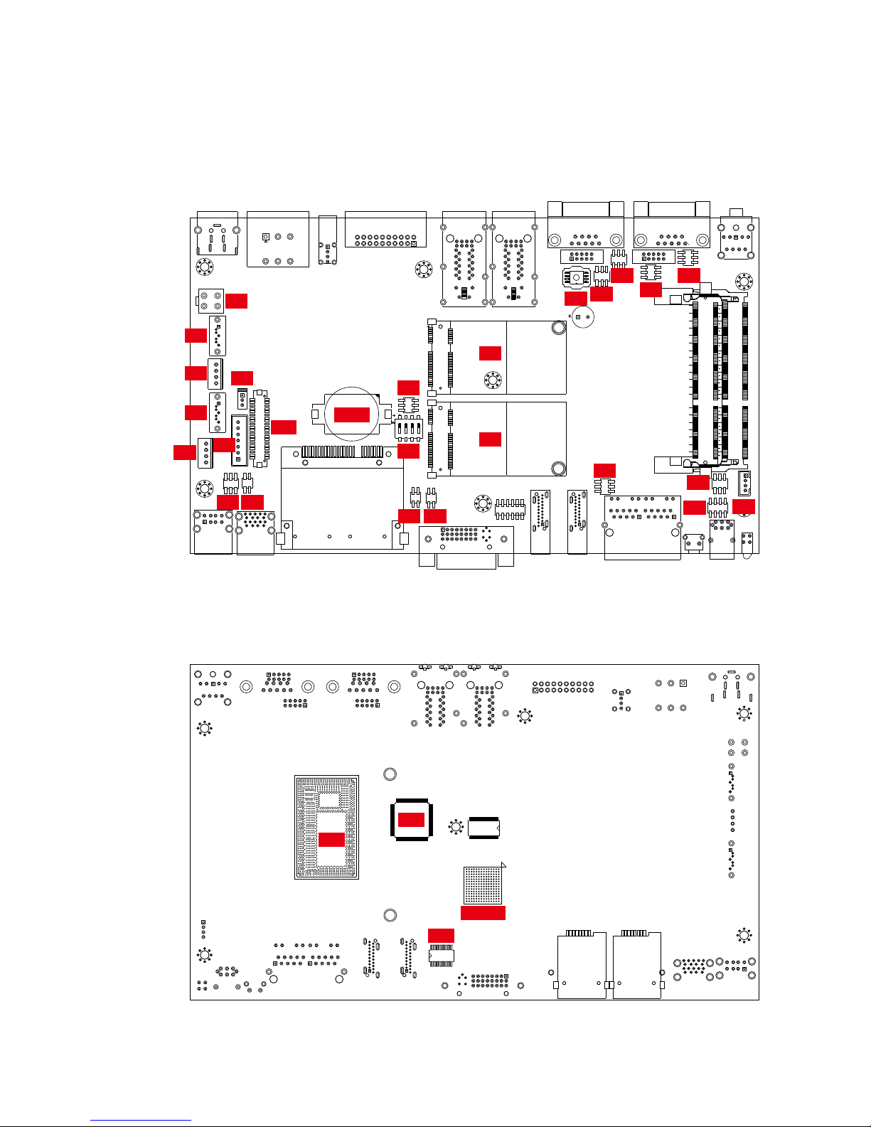
2.3 Main Board Expansion Connectors
2.3.2 Rear View of MTC-4021 Main Board With Connector Location
TPM
PLX-8608
SIO
CPU
2.3.1 Front View of MTC-4021 Main Board With Connector Location
J2
J1
J3
J5
J6
J4
JP1
JP3
JP2
JP4
JP5
JP6
JP7JP8
JP9
JP10 JP11
BIOS
CN16
CN18
CN17
CN19
CON1
Battery
SW1
CN15
Page 25
18
GETTING TO KNOW YOUR MTC-4021©Vecow MTC-4021 User Manual
2.3.3 J6 Miscellaneous Pin Header
This pin header can be used as a backup for following functions, hard drive
LED indicator, reset button, power LED indicator, and power-on/ off button,
which already can be accessed by front panel and top panel. The pinouts of
Miscellaneous port are listed in following table:
Group Pin No. Description
HDD LED
1 HDD_LED_P
3 HDD_LED_N
RESET BUTTON
5 FP_RST_BTN_N
7 GND
POWER LED
2 PWR_LED_P
4 PWR_LED_N
POWER BUTTON
6 FP_PWR_BTN_IN
8 GND
J6
Page 26
19
GETTING TO KNOW YOUR MTC-4021
Pin No. Denition Pin No. Denition Pin No. Denition
1 PANEL_VDD 15 GND 29 GND
2 TXO0- 16 TXOC+ 30 TXE2-
3 PANEL_VDD 17 GND 31 GND
4 TXO0+ 18 TXO3- 32 TXE2+
5 PANEL_VDD 19 GND 33 GND
6 TXO1- 20 TXO3+ 34 TXEC-
7 GND 21 GND 35 GND
8 TXO1+ 22 TXE0- 36 TXEC+
9 GND 23 GND 37 GND
10 TXO2- 24 TXE0+ 38 TXE3-
11 GND 25 GND 39 LVDS_DET#
12 TXO2+ 26 TXE1- 40 TXE3+
13 GND 27 GND
14 TXOC- 28 TXE1+
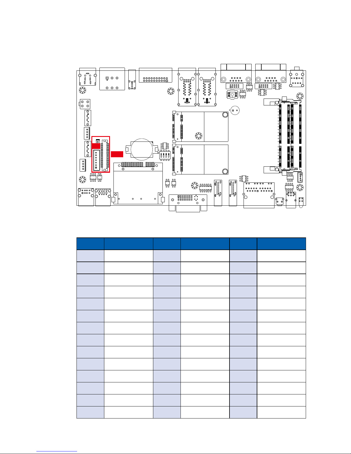
2.3.4 CON1 (LVDS), J2
MTC-4021 supports dual-channel 24-bit LVDS display, up to 1920 x 1200 pixels
resolution. The pin assignments of CON1 are listed in the following table:
J2
CON1
Page 27
20
GETTING TO KNOW YOUR MTC-4021©Vecow MTC-4021 User Manual
The LCD inverter is connected to J2 via a JST 7-pin, 2.5mm connector providing
+5V/ +12V power to LCD display. The pin assignments are listed in the following
table:
Pin No. Denition Pin No. Denition
1 +5V 5 GND
2 +12V 6 GND
3 +12V 7 LBKLT_EN
4 LBKLT_CTL
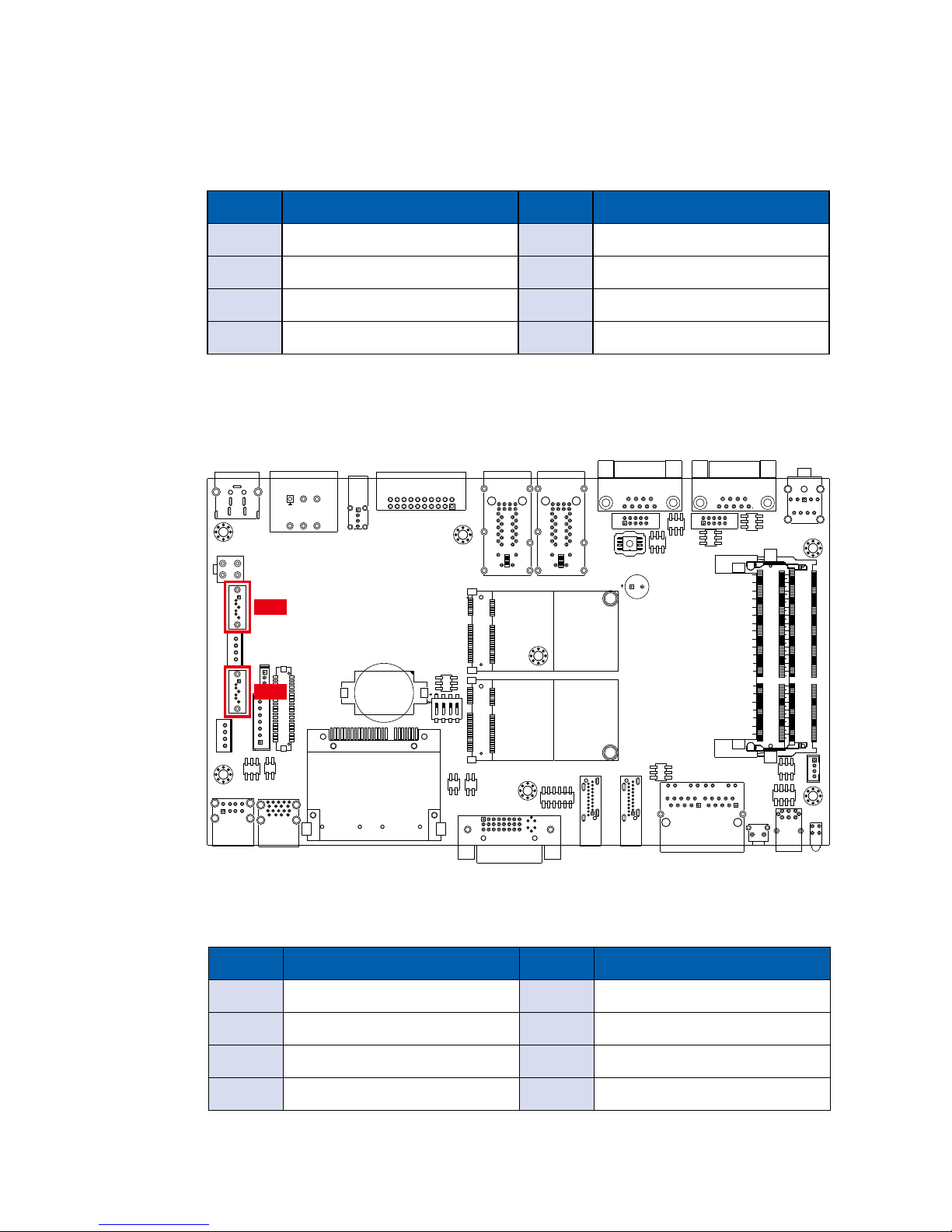
2.3.5 CN17, CN19 : SATA III Connector
There are 2 onboard high performance Serial ATA III (SATA III) on MTC-4021.
It supports higher storage capacity with less cabling effort and smaller required
space. The pin assignments of CN17 and CN19 are listed in the following table:
Pin No. Denition Pin No. Denition
1 GND 5 RXN
2 TXP 6 RXP
3 TXN 7 GND
4 GND
CN17
CN19
Page 28
21
GETTING TO KNOW YOUR MTC-4021
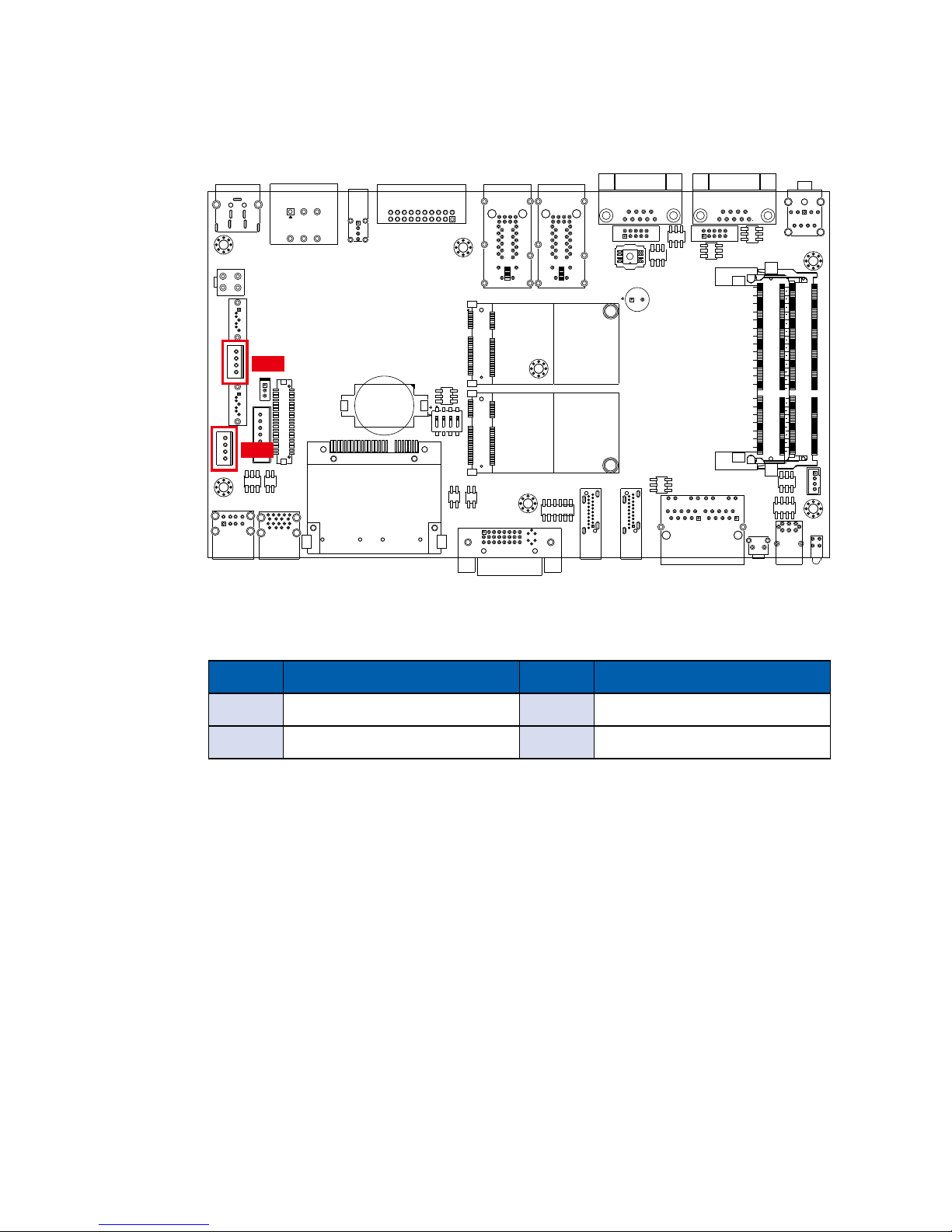
2.3.6 J1, J3 : SATA Power Connector
The MTC-4021 also equip with 2 SATA power connector. It supports 5V (Up to
2A) and 12V (Up to 1A) current to the hard drive or SSD. The pin assignments
of J1 and J3 are listed in the following table:
Pin No. Denition Pin No. Denition
1 +12V 3 GND
2 GND 4 +5V
J1
J3
Page 29
22
GETTING TO KNOW YOUR MTC-4021©Vecow MTC-4021 User Manual
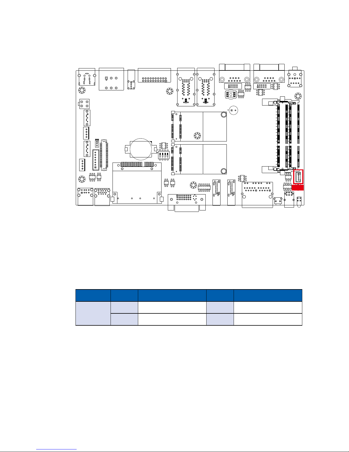
2.3.7 J4 : Internal USB
The MTC-4021 main board provide one expansion USB port using plug-andplay for Dongle Key or LCD touch Panel. The USB interface supports 480 Mbps
transfer rate which comply with high speed USB specication Rev. 2.0.
The USB interface is accessed through one 4-pin JST 2.0mm connector. You
will need an adapter cable if you use a standard USB connector. The adapter
cable has a 4-pin connector on one end and a USB connector on the other.
The pin assignments of J4 are listed in the following table:
J4
Connector Pin No. Description Pin No. Description
J4
1 USB_VCC 3 USBD+
2 USBD- 4 GND
Page 30
23
GETTING TO KNOW YOUR MTC-4021
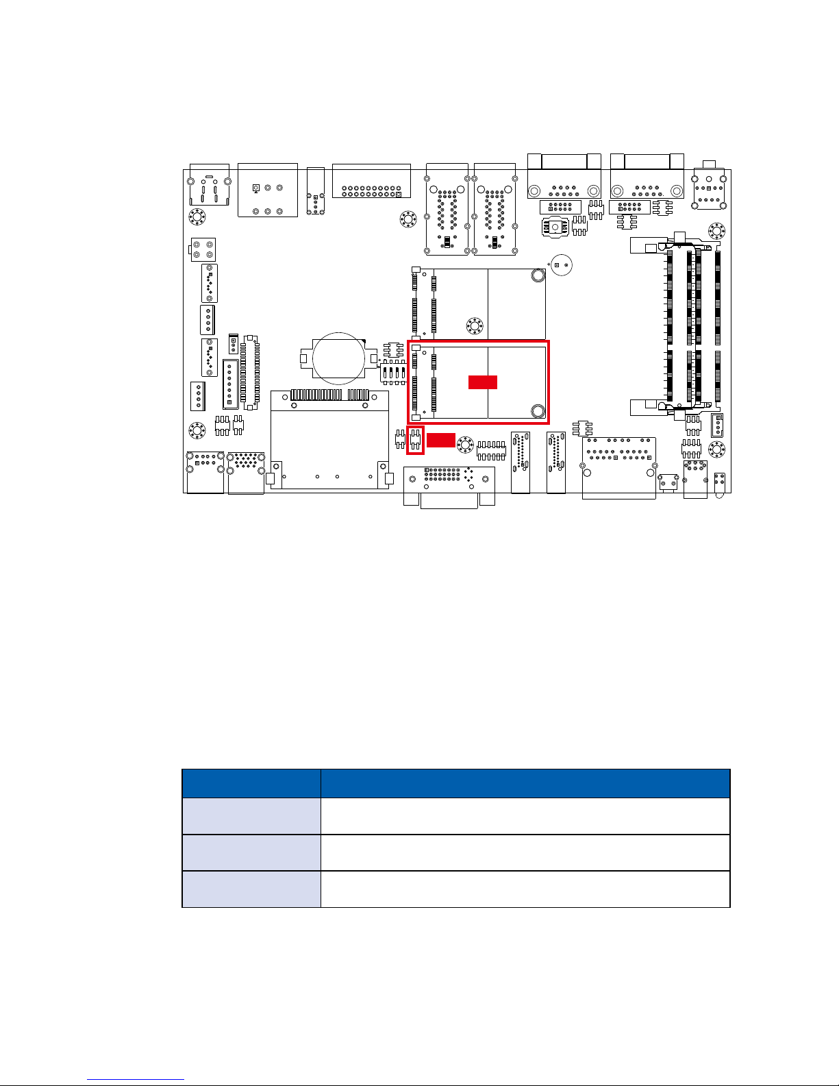
2.3.8 CN18 : Mini PCIe, mSATA
Both mSATA and Mini PCIe share the same form factor and similar electrical
pinout assignments on their connectors. There was no clear mechanism to
distinguish if a mSATA drive or a Mini PCIe device is plugged into the socket
until recently that SATA I/O issued an ECN change (ECN #045) to redene Pin43 on mSATA connector as “no connect” instead of “return current path” (or
GND).
When an mSATA drive is inserted, its Pin-43 is “no connect”, and the respective
pin on the socket is being pulled-up to logic 1. When a Mini PCIe device is
inserted, its Pin-43 forces the respective pin on the socket to ground, or logic 0.
MTC-4021 using JP11 Pin-43 status designed for switching between mSATA
drive and Mini PCIe device.
CN18
JP11
Header Interface
1-2 Auto Detection
2-4 Mini PCIe
1-3 mSATA
Page 31
24
GETTING TO KNOW YOUR MTC-4021©Vecow MTC-4021 User Manual
Pin No. Signal Name Pin No. Signal Name
1 WAKE# 2 +3.3Vaux
3 Reserved 4 GND
5 Reserved 6 +1.5V
7 CLKREQ# 8 UIM_PWR
9 GND 10 UIM_DATA
11 REFCLK- 12 UIM_CLK
13 REFCLK+ 14 UIM_RESET
15 GND 16 UIM_VPP
Mechanical Key
17 Reserved 18 GND
19 Reserved 20 reserved
21 GND 22 PERST#
23 PERn0 24 +3.3Vaux
25 PERp0 26 GND
27 GND 28 +1.5V
29 GND 30 SMB_CLK
31 PETn0 32 SMB_DATA
33 PETp0 34 GND
35 GND 36 USB_D-
37 GND 38 USB_D+
39 +3.3Vaux 40 GND
41 +3.3Vaux 42 Reserved
43 GND 44 Reserved
45 Reserved 46 Reserved
47 Reserved 48 1.5V
49 Reserved 50 GND
51 Reserved 52 +3.3Vaux
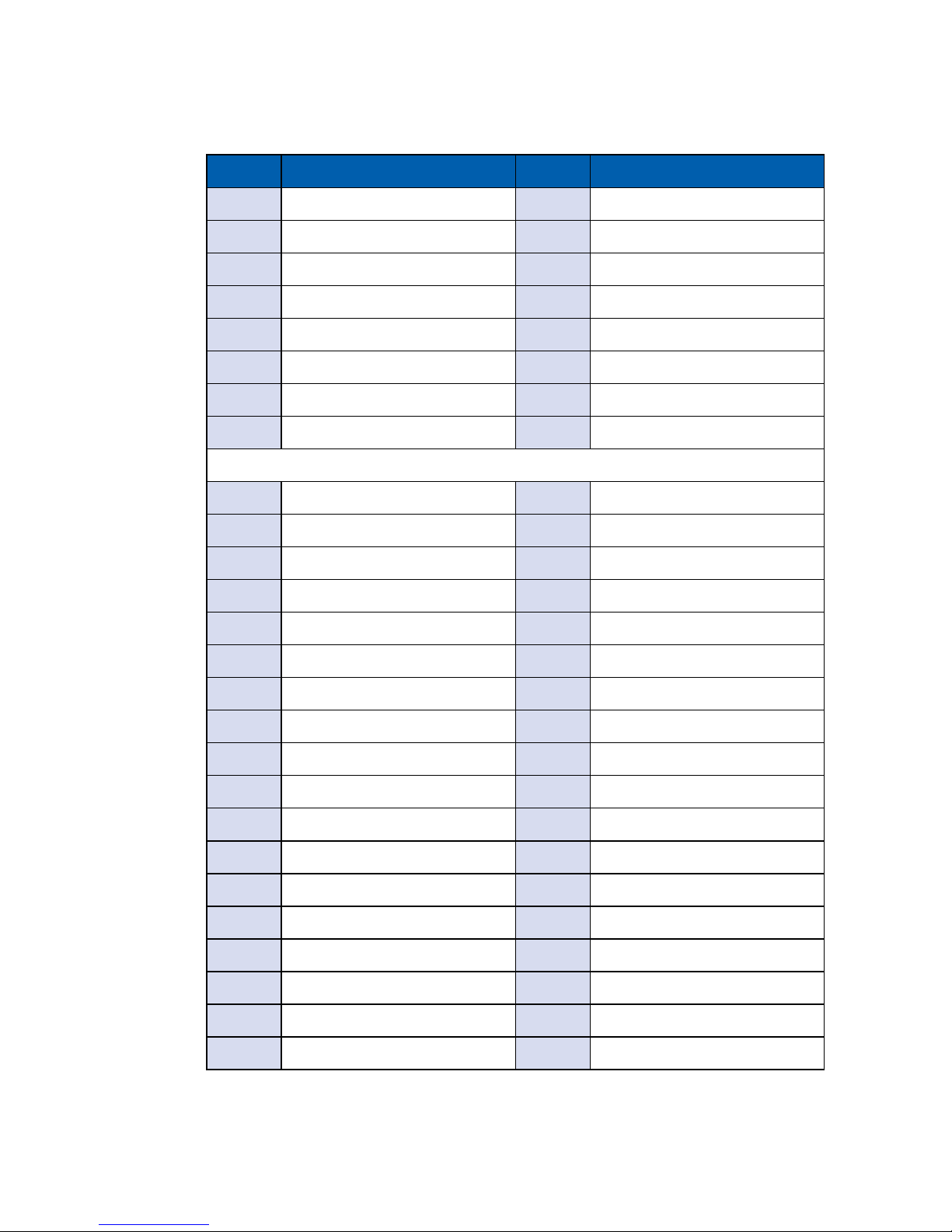
The pin assignments of CN18 are listed in the following table:
Page 32
25
GETTING TO KNOW YOUR MTC-4021
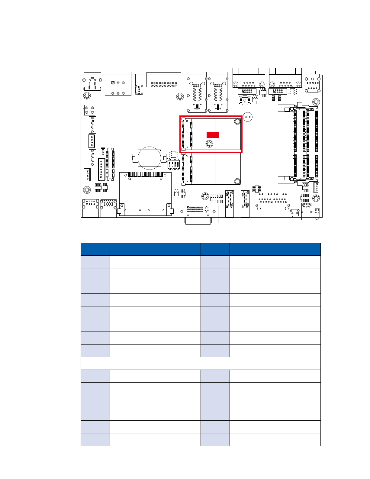
2.3.9 CN16 : Mini PCIe
CN16
Pin No. Signal Name Pin No. Signal Name
1 WAKE# 2 +3.3Vaux
3 Reserved 4 GND
5 Reserved 6 +1.5V
7 CLKREQ# 8 UIM_PWR
9 GND 10 UIM_DATA
11 REFCLK- 12 UIM_CLK
13 REFCLK+ 14 UIM_RESET
15 GND 16 UIM_VPP
Mechanical Key
17 Reserved 18 GND
19 Reserved 20 reserved
21 GND 22 PERST#
23 PERn0 24 +3.3Vaux
25 PERp0 26 GND
27 GND 28 +1.5V
The pin assignments of CN16 are listed in the following table:
Page 33
26
GETTING TO KNOW YOUR MTC-4021©Vecow MTC-4021 User Manual
29 GND 30 SMB_CLK
31 PETn0 32 SMB_DATA
33 PETp0 34 GND
35 GND 36 USB_D-
37 GND 38 USB_D+
39 +3.3Vaux 40 GND
41 +3.3Vaux 42 Reserved
43 GND 44 Reserved
45 Reserved 46 Reserved
47 Reserved 48 1.5V
49 Reserved 50 GND
51 Reserved 52 +3.3Vaux
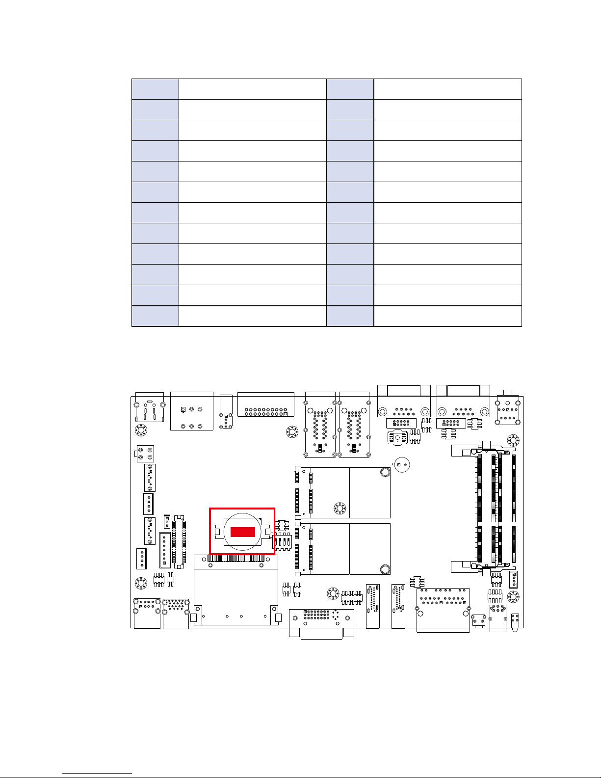
2.3.10 Battery
The MTC-4021’s real-time clock is powered by a lithium battery. It is Equipped
with Panasonic BR2032 190mAh lithium battery. It is recommended that you
not replace the lithium battery on your own. If the battery needs to be changed,
please contact the Vecow RMA service team.
Battery
Page 34
27
GETTING TO KNOW YOUR MTC-4021
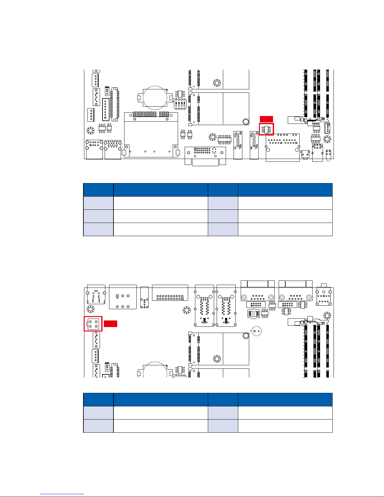
2.3.11 J5 : LAN2 I210 SDP
The pin assignments of J5 are listed in the following table:
Pin No. Function Pin No. Function
1 LAN2_SDP0 4 LAN2_SDP3
2 LAN2_SDP1 5 GND
3 LAN2_SDP2 6 GND
J5
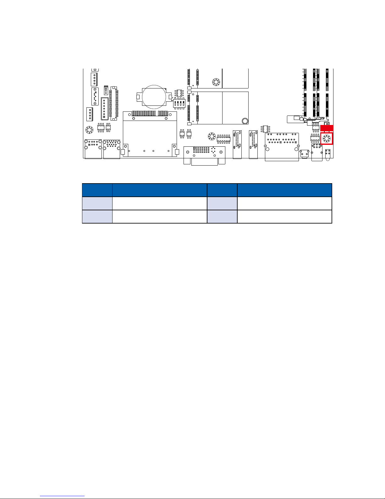
2.3.12 CN15 : +12V_SB Output
The pin assignments of CN15 are listed in the following table:
Pin No. Function Pin No. Function
1 GND 3 +12V_SB
2 GND 4 +12V_SB
CN15
Page 35
28
GETTING TO KNOW YOUR MTC-4021©Vecow MTC-4021 User Manual
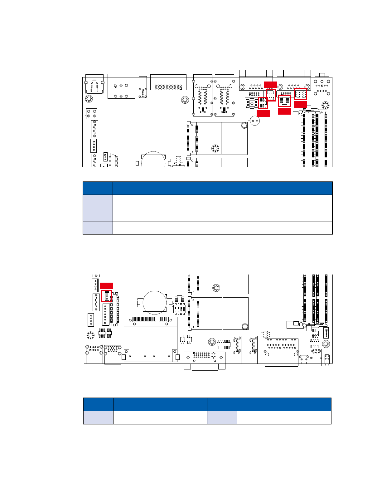
2.3.13 J4 Internal USB2.0
The pin assignments of J4 are listed in the following table:
Pin No. Function Pin No. Function
1 Vcc 3 D+
2 D- 4 GND
J4
Page 36
29
GETTING TO KNOW YOUR MTC-4021
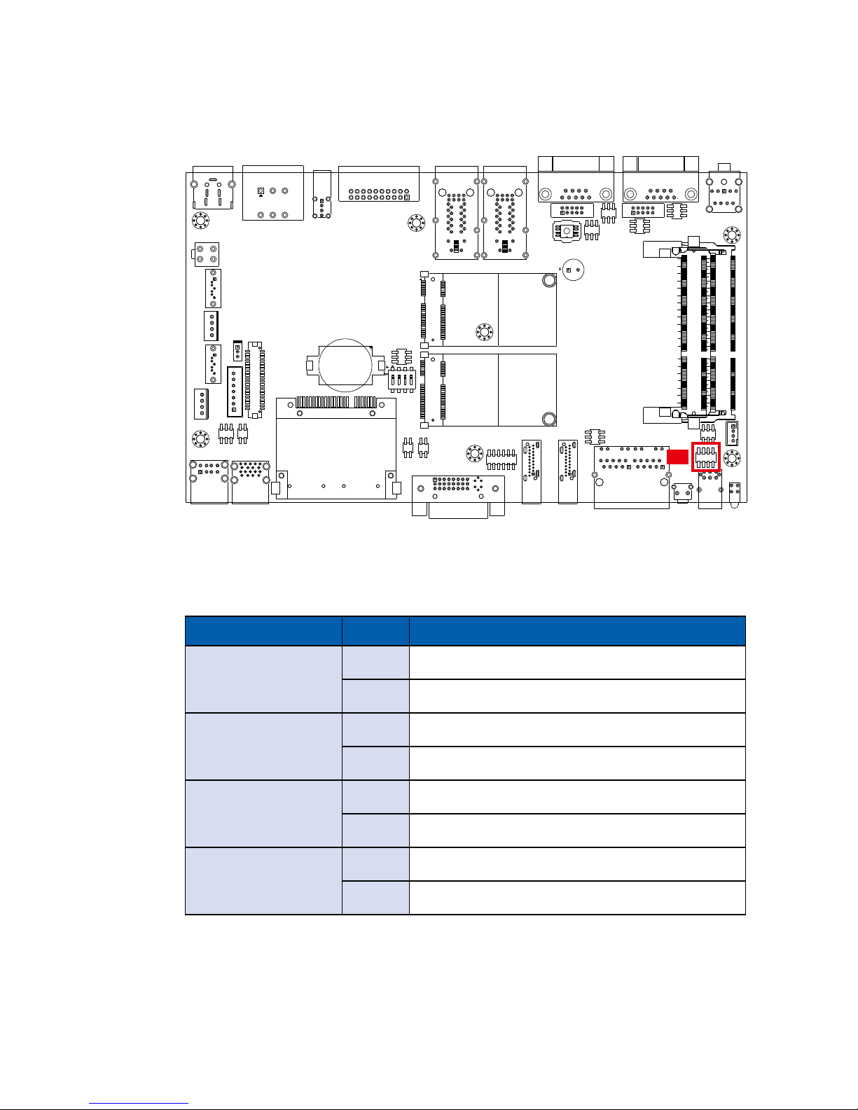
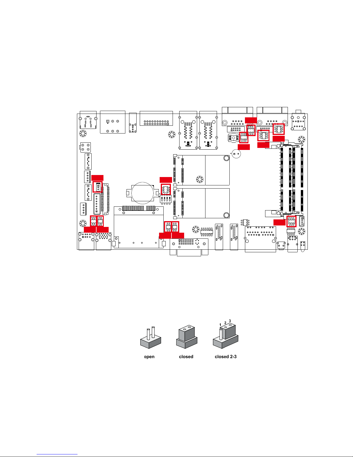
2.4 Main Board Jumper Settings
2.4.1 Front View of MTC-4021 Main Board with Jumper Location
You may congure your card to match the needs of your application by setting
jumpers. A jumper is a metal bridge used to close an electric circuit. It consists
of two metal pins and a small metal clip (often protected by a plastic cover) that
slides over the pins to connect them. To “close” a jumper, you connect the pins
with the clip. To “open” a jumper, you remove the clip. Sometimes a jumper will
have three pins, labeled 1, 2 and 3. In this case you would connect either pins 1
and 2, or 2 and 3.
The figure below is the top view of the MTC-4021 main board which is the
main board used in the MTC-4021 Series system. It shows the location of the
jumpers.
JP1
JP2
JP3
JP4
JP9
JP11
JP6
JP5
JP7
JP8
JP10
Page 37
30
GETTING TO KNOW YOUR MTC-4021©Vecow MTC-4021 User Manual
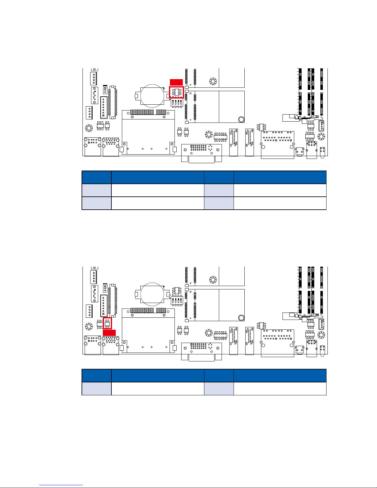
2.4.3 JP5 : LVDS Backlight, Power Selection
JP5
JP5 provides LVDS voltage selection function, closing Pin 1, 2 is for 3.3V LVDS
power input; closing Pin 2, 3 is for 5V LVDS power input.
Pin No. Function Pin No. Function
1-2 +3.3V (Default) 2-3 +5V
2.4.2 JP1, JP2, JP3, JP4
COM 1 to COM 4 Pin 9 Function:
Pin No. RI/ +5V/ +12V
1-2 +12V
3-4 +5V
5-6 RI
JP1
JP2
JP3
JP4
Page 38
31
GETTING TO KNOW YOUR MTC-4021
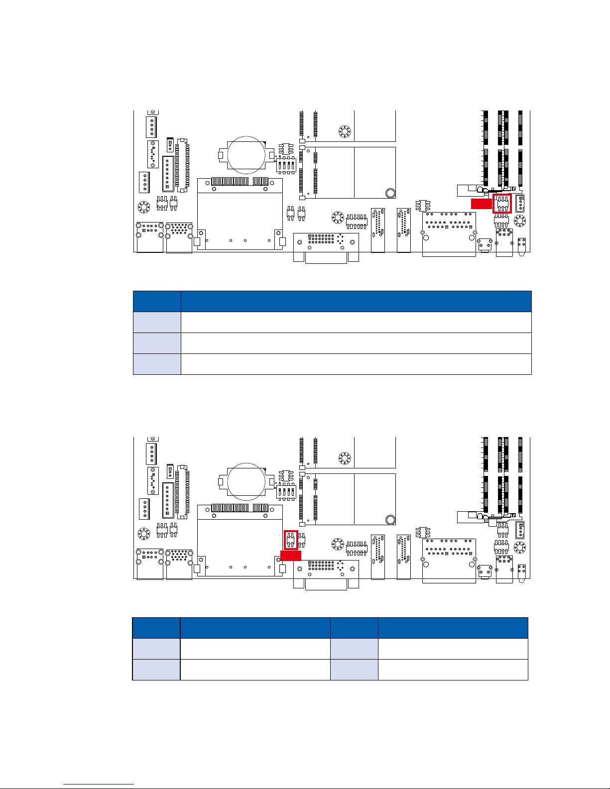
2.4.4 JP6 CMOS/ME
CMOS Header ME Header
1-2 Normal 2-4 Normal
2-3 Clear CMOS 4-6 Clear ME
JP6
2.4.5 JP7 External USB3.0/2.0 Power Select
Header Power Header Power
1-2 +5V Standby Power 3-4 +5V System Power
JP7
Page 39
32
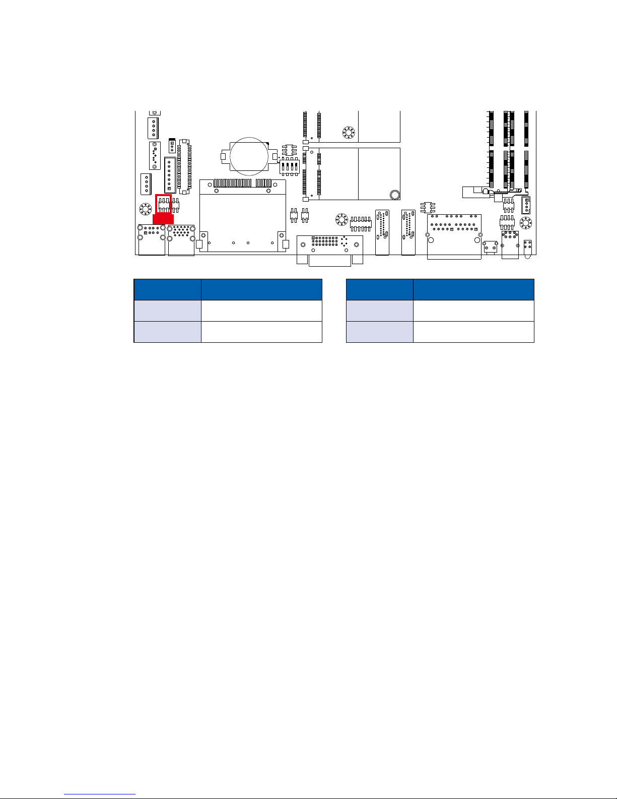
GETTING TO KNOW YOUR MTC-4021©Vecow MTC-4021 User Manual
2.4.7 JP10 : MCU Spy-bi Wire Interface for Download FW
JP10
The pin assignments of JP10 are listed in the following table:
Pin No. Function Pin No. Function
1 GND 3 3.3V_MCU
2 MCU_RST# 4 MCU_PRG
2.4.6 JP9 Internal USB Power Select
JP9
Internal USB PWR Select:
JP9 +V5A/ +V5/ +V3.3
1-2 +5V Standby
3-4 +5V
5-6 +3.3V
Page 40
33
GETTING TO KNOW YOUR MTC-4021
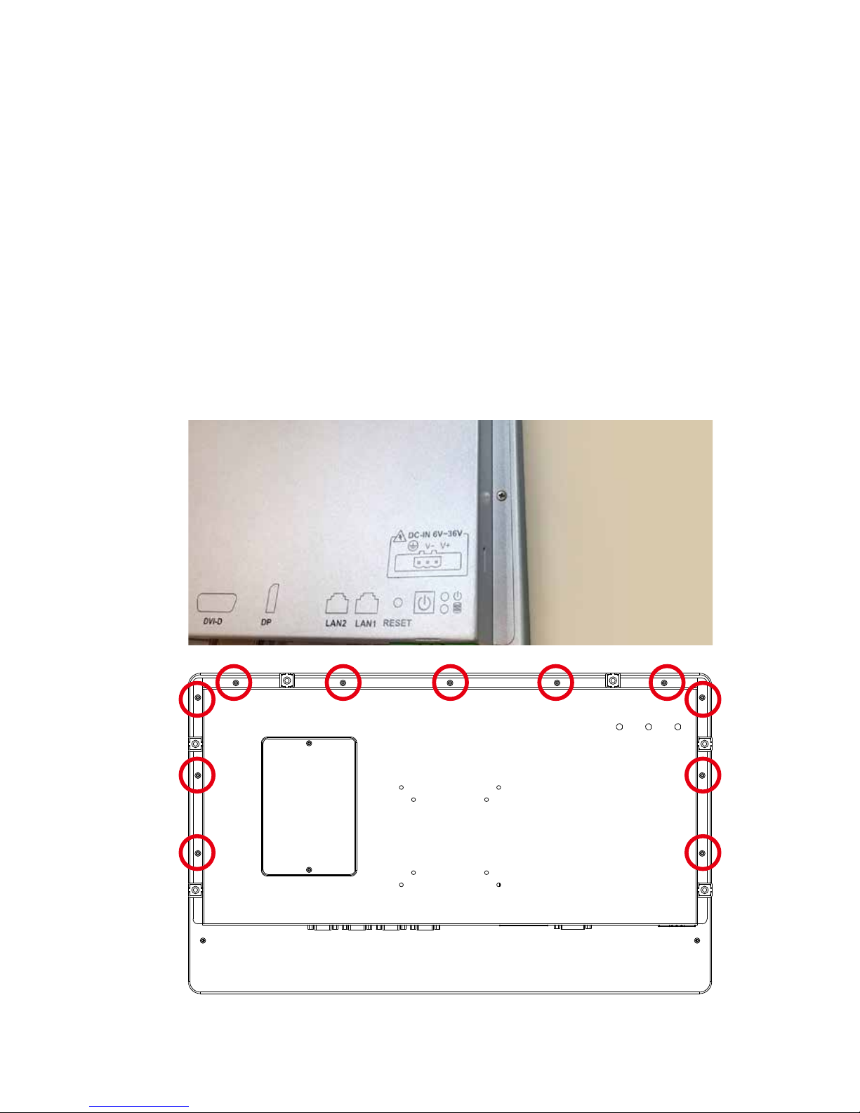
2.4.8 JP8 Backlight Control Level Select
JP8
Dimming Header
1-3 3.3V
3-5 5V
On/ Off Header
2-4 3.3V
4-6 5V
Page 41
34
HARDWARE INSTALLATION©Vecow MTC-4021 User Manual
3
SYSTEM SETUP
3.1 How to Open Your MTC-4021
Step 1 Remove 11pcs FH M3 screws (circled in red) from back cover.
3.1.1 MTC-4021
“Please make sure to assemble the system in an anti-static environment.”
Page 42
35
HARDWARE INSTALLATION
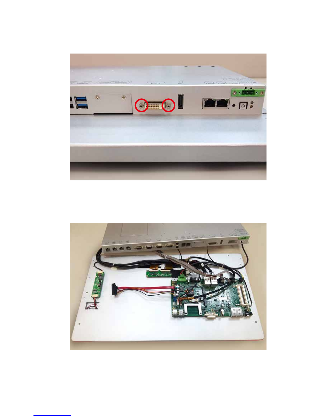
Step 2 Remove 2pcs #4-40 screws (circled in red) from I/O.
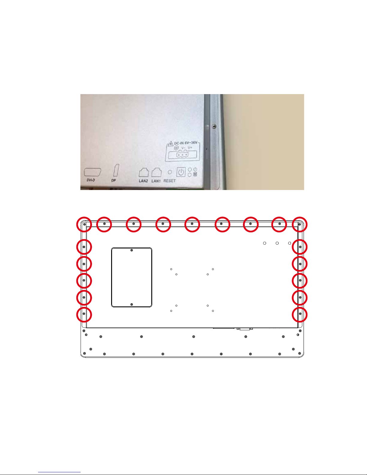
Step 3 Now you can take off the back cover. Please do remove the back
cover carefully.
Page 43
36
HARDWARE INSTALLATION©Vecow MTC-4021 User Manual
3.1.2 MTC-4021 with IP65
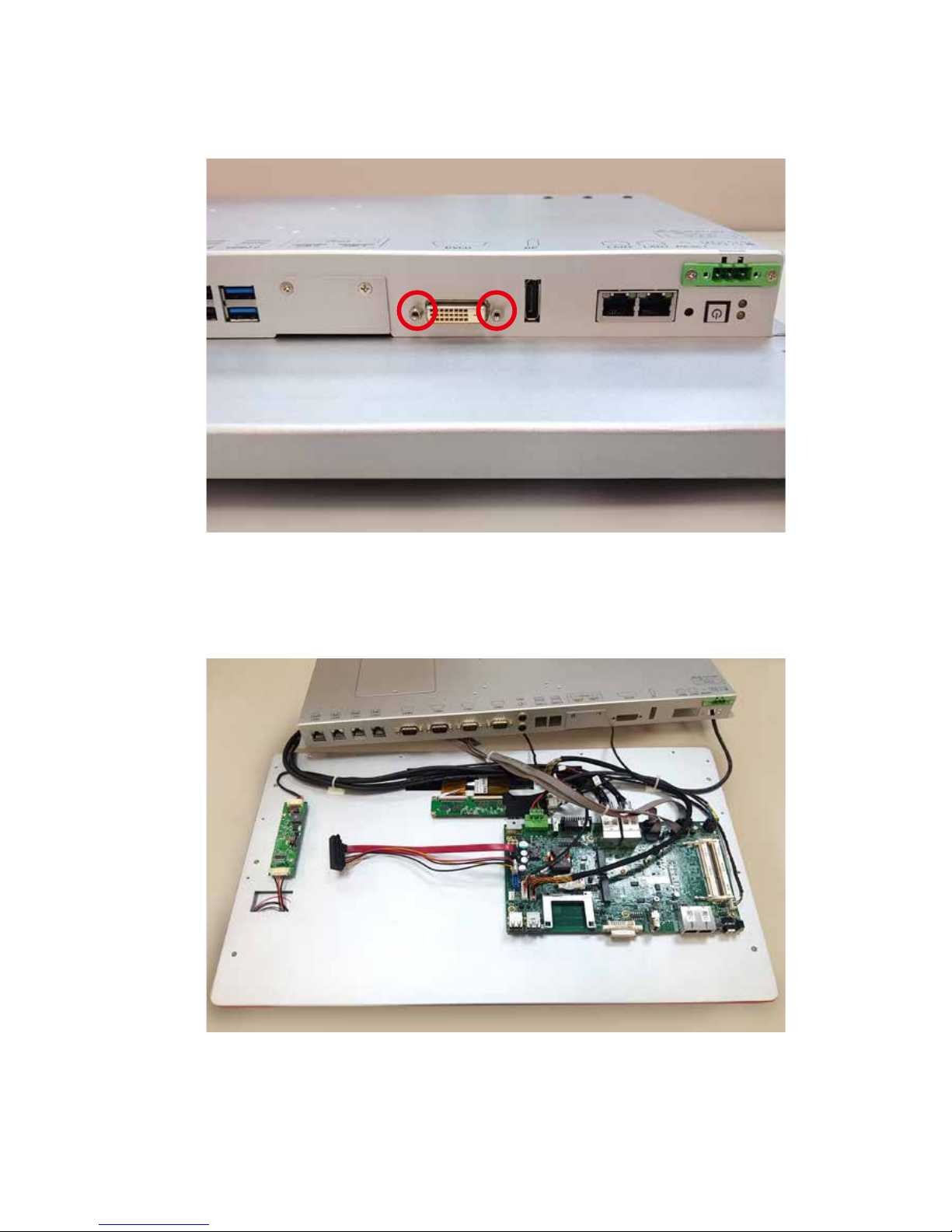
Step 1 Remove 19pcs FH M3 screws (circled in red) from back cover.
Page 44
37
HARDWARE INSTALLATION
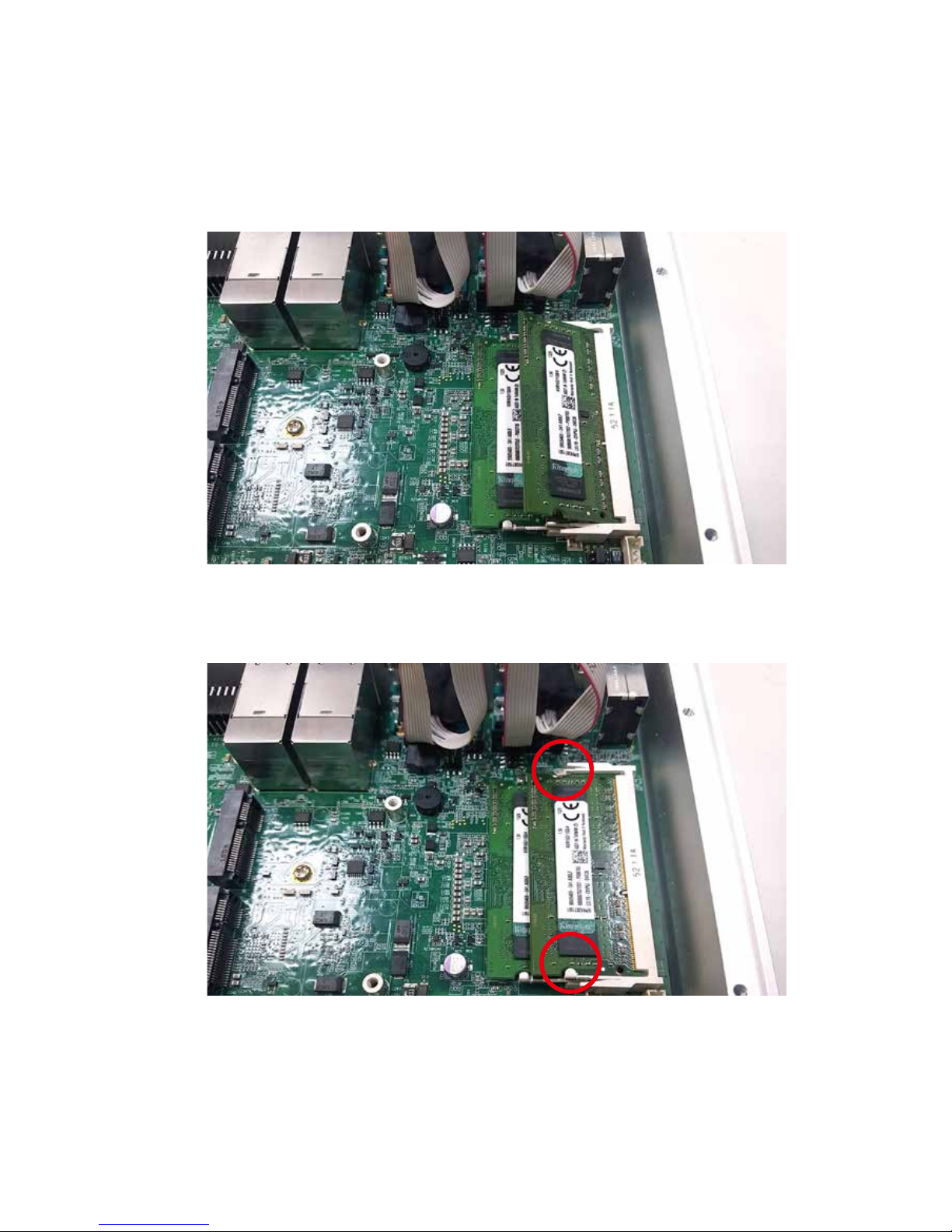
Step 2 Remove 2pcs #4-40 screws (circled in red) from I/O.
Step 3 Now you can take off the back cover. Please do remove the back
cover carefully.
Page 45
38
HARDWARE INSTALLATION©Vecow MTC-4021 User Manual
3.2 Installing DDR3L SO-DIMM Modules
Step 1 Install DDR3L RAM module into SO-DIMM socket.
Step 2 Make sure the RAM module is locked by the memory slot.
Page 46
39
HARDWARE INSTALLATION
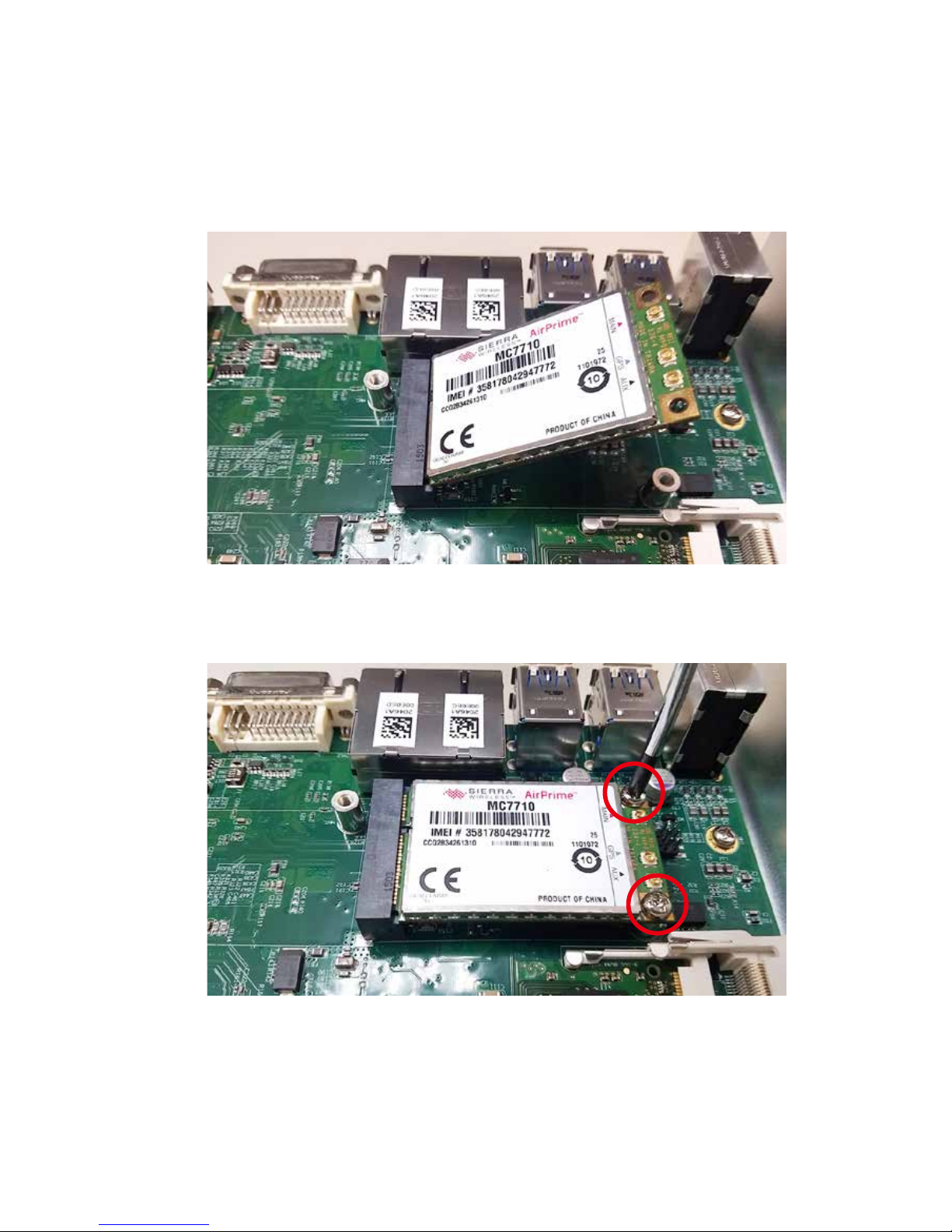
3.3 Installing Mini PCIe Cards
Step 1 Install Mini PCIe card into Mini PCIe socket.
Step 2 Fasten 2pcs M2.5 screws.
Page 47
40
HARDWARE INSTALLATION©Vecow MTC-4021 User Manual
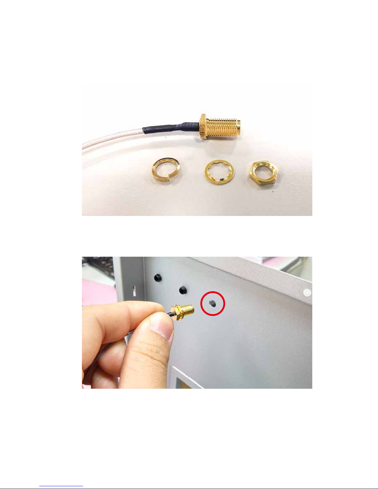
3.4 Installing Antenna Cable
2 1 3
Step 1 Check Antenna cable and washers..
Step 2 Remove the rubber cork on back cover.
(Pick up the location you want.)
Page 48
41
HARDWARE INSTALLATION
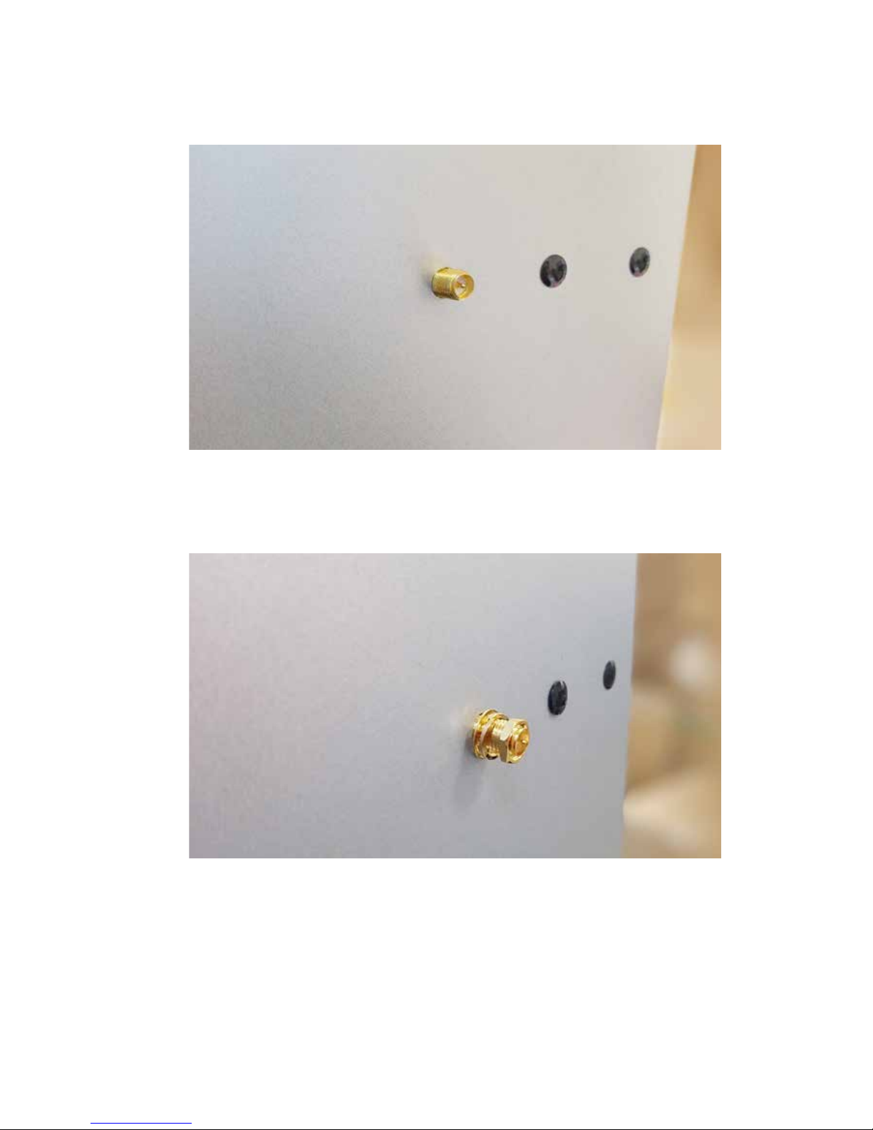
Step 3 Put Antenna cable connector into the hole on back cover.
Step 4 Fasten the washer 1, washer 2 and washer 3 on Antenna cable
connector.
Page 49
42
HARDWARE INSTALLATION©Vecow MTC-4021 User Manual
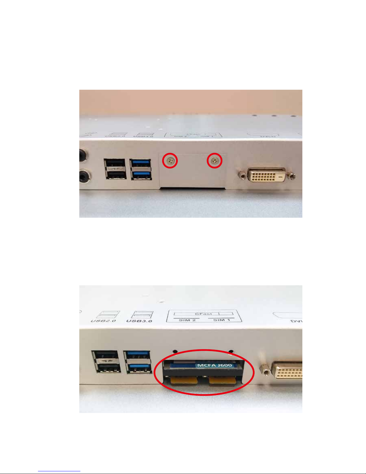
3.5 Installing CFast Card and SIM Card
Step 2 Make sure the system is power-off and unplugged.
Step 1 Remove 2pcs F-M3x4 screws on CFast & SIM Card cover on
back cover.
Step 4 Insert CFast card and SIM card and push to lock.
Step 3 Before Inserting SIM card, make sure the system power is not
plugged.
Page 50
43
HARDWARE INSTALLATION
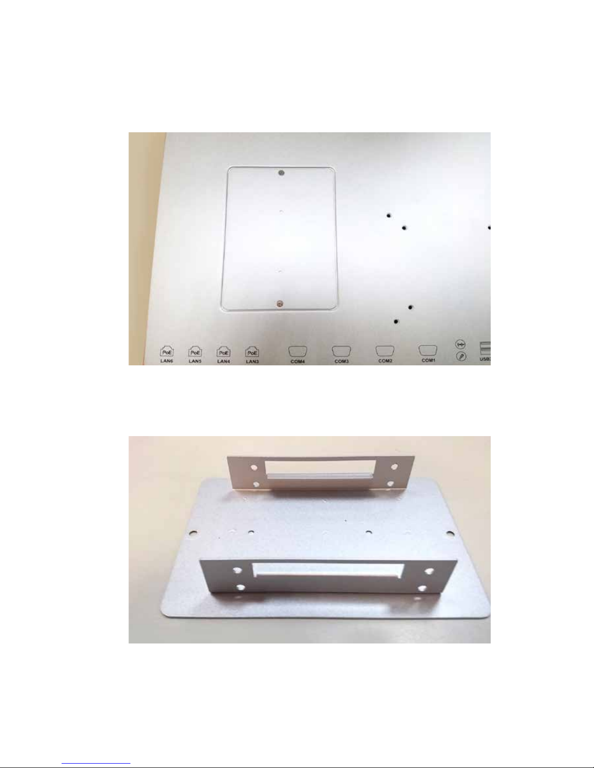
3.6 Installing SSD/ HDD
Step 2 Take SSD/ HDD Tray and face the bracket side up.
Step 1 Remove 2pcs M3x4 screws of SSD/ HDD Tray from back cover.
Page 51
44
HARDWARE INSTALLATION©Vecow MTC-4021 User Manual
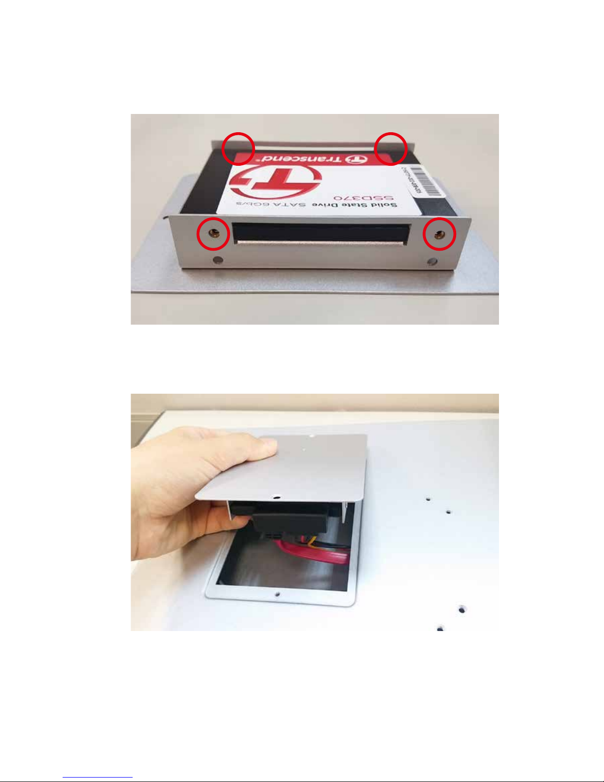
Step 4 Plug-in SATA cable to SSD/HDD on the tray.
Step 3 Fasten 4pcs M3x6 screws (marked in red) to x the SSD/ HDD on
the tray.
Page 52
45
HARDWARE INSTALLATION
3.7 Mounting MTC-4021
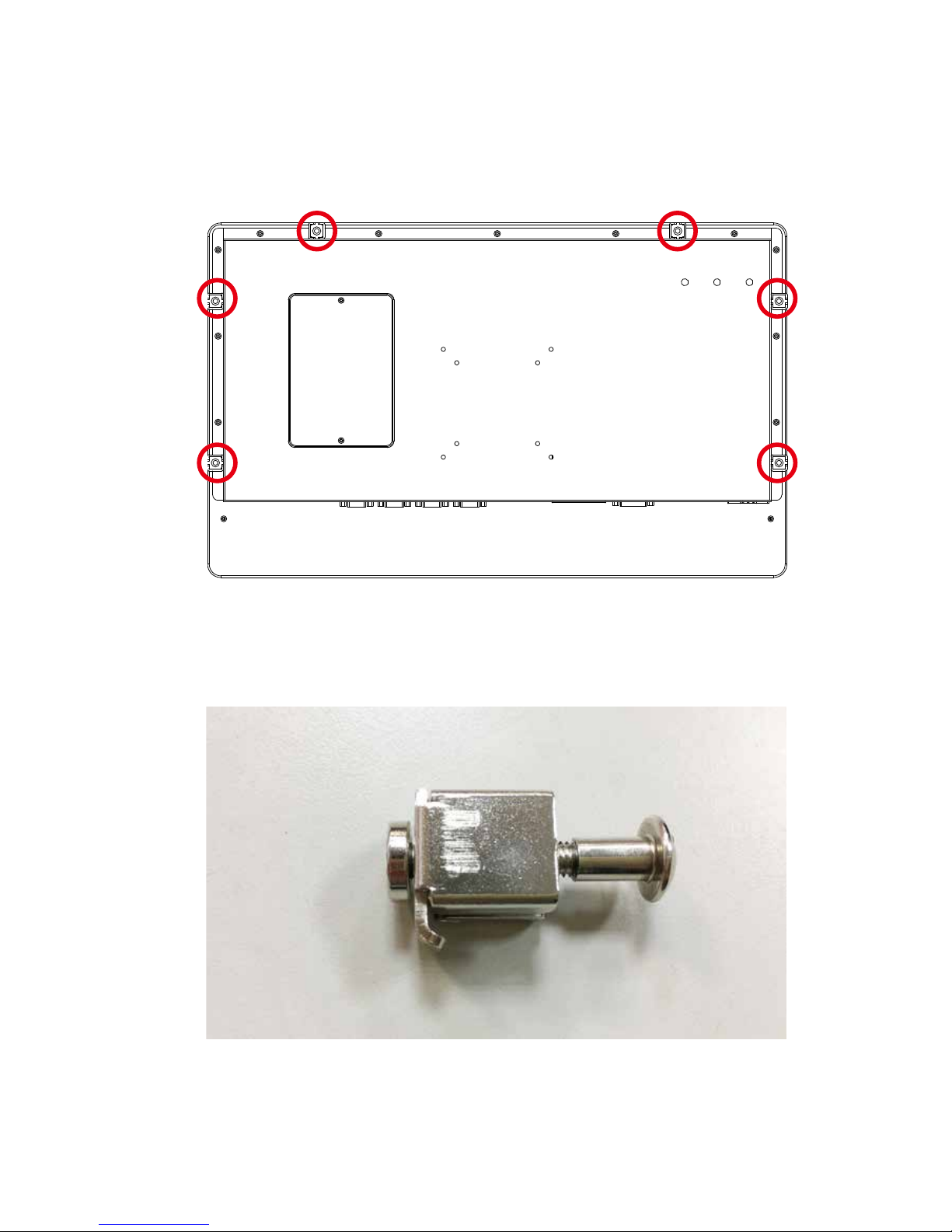
Step 1 Make sure your M5x20 screws and screw tongues for Panel
mount.
Panel mount position
Page 53
46
HARDWARE INSTALLATION©Vecow MTC-4021 User Manual
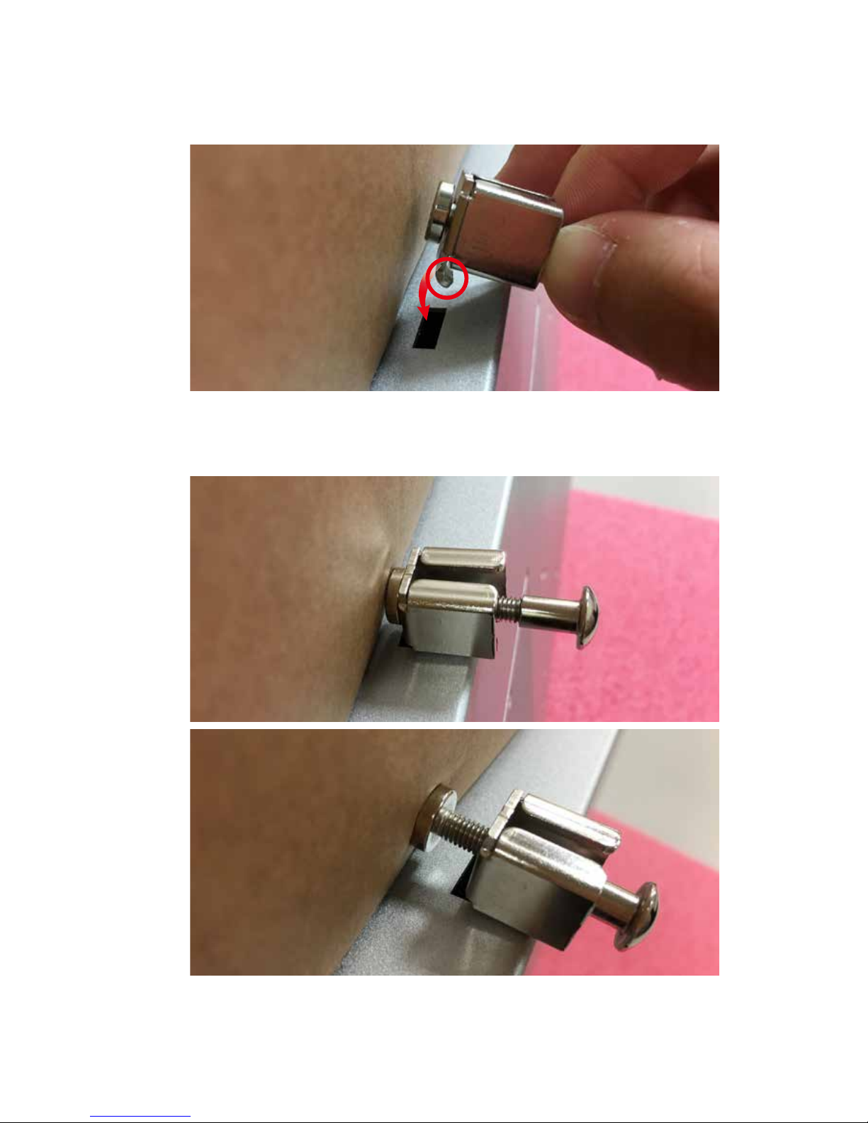
Step 3 Fasten the M5x20 screw.
Step 2 Make sure the screw tongues match MTC-4021 back cover.
Page 54
47
BIOS AND DRIVER SETTING
BIOS AND DRIVER
4
4.1 BIOS Settings
The board uses UEFI BIOS that is use Serial Peripheral Interface (SPI)
Flash. The SPI Flash contains the BIOS Setup program, POST, the PCI autoconfiguration utility, LAN, EEPROM information, and Serial port support. The
BIOS setup program is accessed by pressing the <Del> key after the PowerOn Self-Test (POST) memory test begins and before the operating system boot
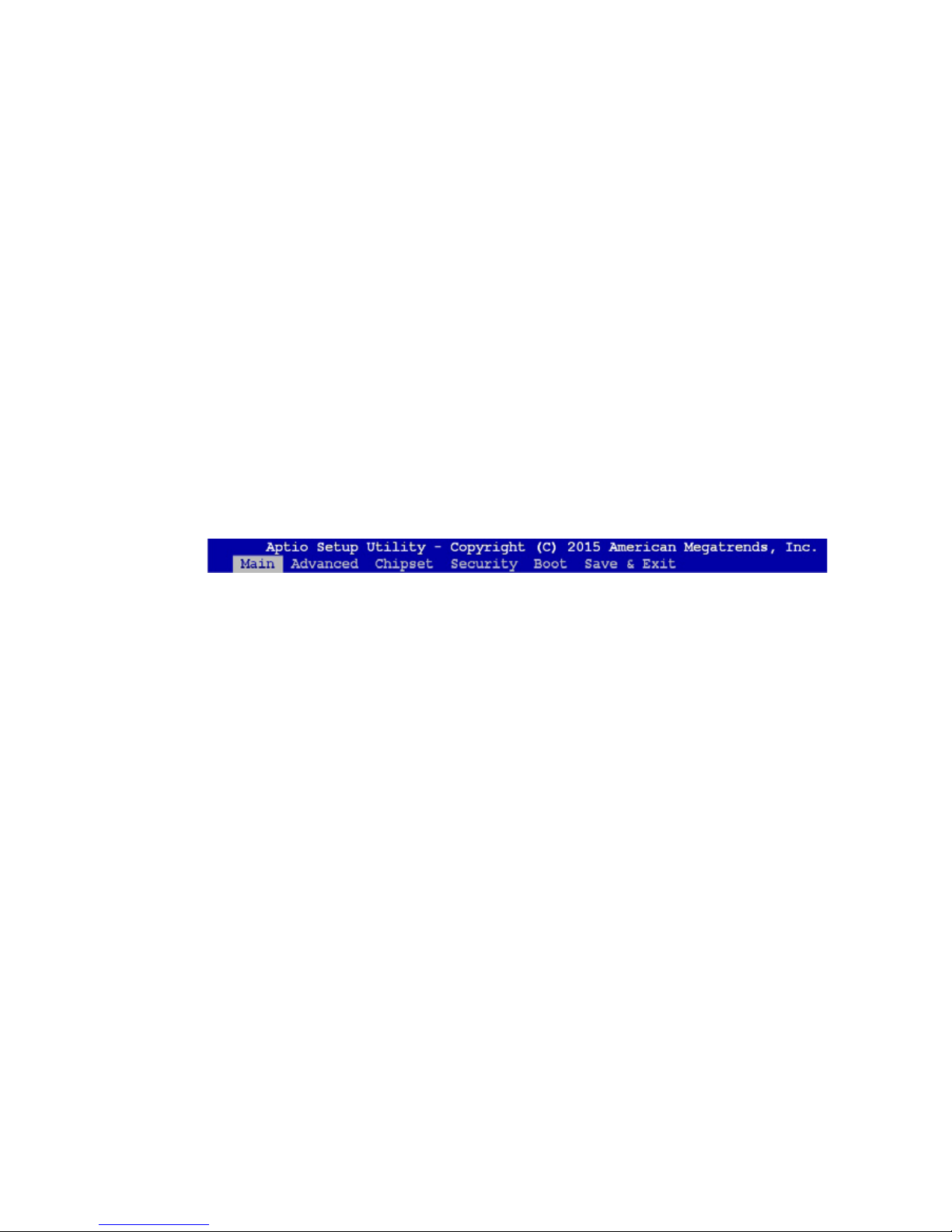
begins. The menu bar is shown below.
Figure 4 1: BIOS Menu Bar
Page 55
48
BIOS AND DRIVER SETTING
©Vecow MTC-4021 User Manual
4.2 Main Menu
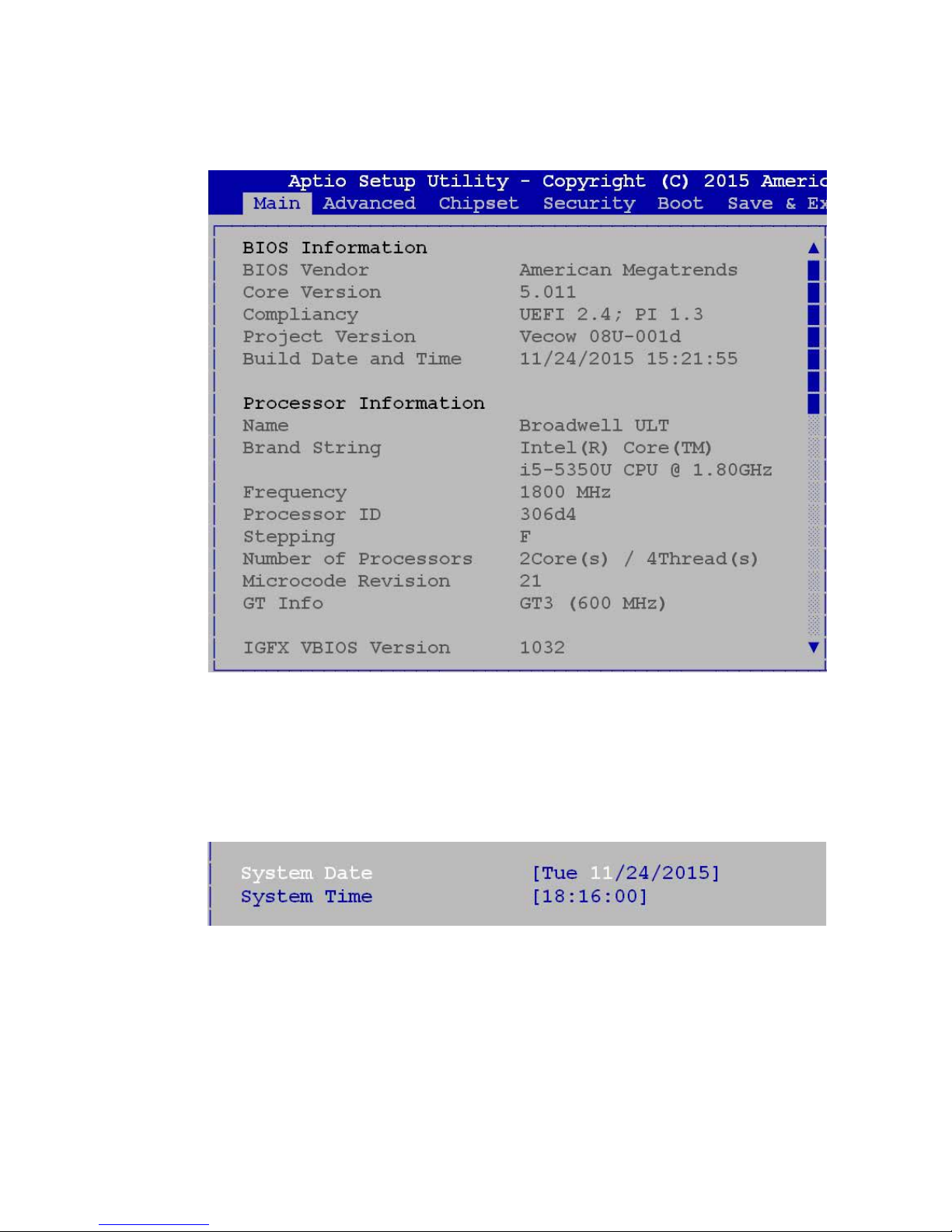
Figure 4 2: BIOS Main screen
System Time/ Date
Press “TAB” key to switch sub-items of value .Then press “+” key or “-“ key
number key for modify value.
Figure 4 2-1: System Time / Date setting
4.2.1 System Time/Date Setting
In this page, you could make sure you CPU type and DRAM type that you are
install into this system.
Page 56
49
BIOS AND DRIVER SETTING
4.3 Advanced Function
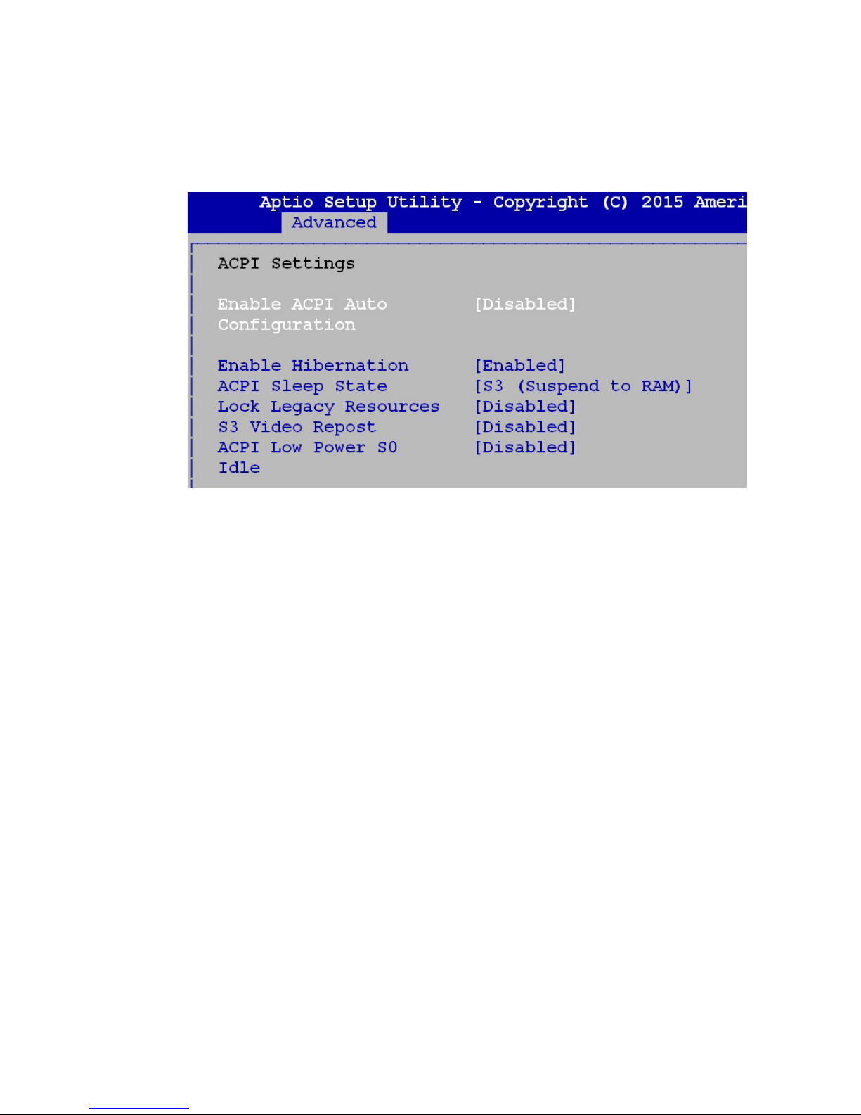
4.3.1 ACPI Setting
Enable ACPI Auto Conguration
This system support ACPI function as auto process. You should Enable /
Disable that depend as your O.S.
Enable Hibernation
It is able to use Hibernate function if O.S support. But some O.S maybe not
effective with this function.
Figure 4 3-1: ACPI Setting setup screen
Page 57

50
BIOS AND DRIVER SETTING
©Vecow MTC-4021 User Manual
4.3.2 CPU Conguration
Intel Virtualization Technology
This for Virtualization Application or platform usage, when enabled, a VMM can
utilize the additional hardware capabilities provided by Vanderpool Technology.
Figure 4-3-2: CPU Conguration setup screen
Page 58
51
BIOS AND DRIVER SETTING
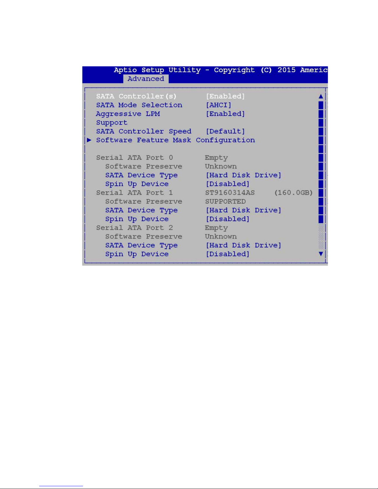
4.3.3 SATA Conguration
SATA Controller(s)
Enables or Disables integrate SATA controller for Storage device use.
SATA Mode Selection
Determines how the SATA transfer mode for operate. Here has two options
for choice [AHCI] / [RAID].
Serial ATA Port 0 to Port 3
This system offers four SATA port for SATA device connection.
Figure 4-3-3: SATA Conguration setup screen
Page 59
52
BIOS AND DRIVER SETTING
©Vecow MTC-4021 User Manual
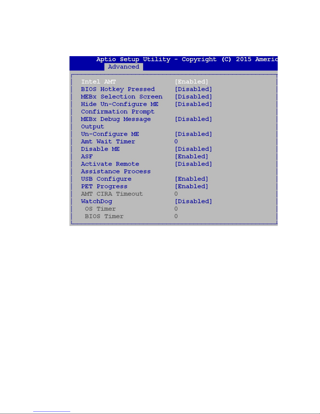
4.3.4 AMT Conguration
Intel AMT
Enables or Disables Intel(R) Active Management Technology BIOS extension.
This option just controls the BIOS extension executes.
Figure 4-3-4: AMT Setup screen
Page 60
53
BIOS AND DRIVER SETTING
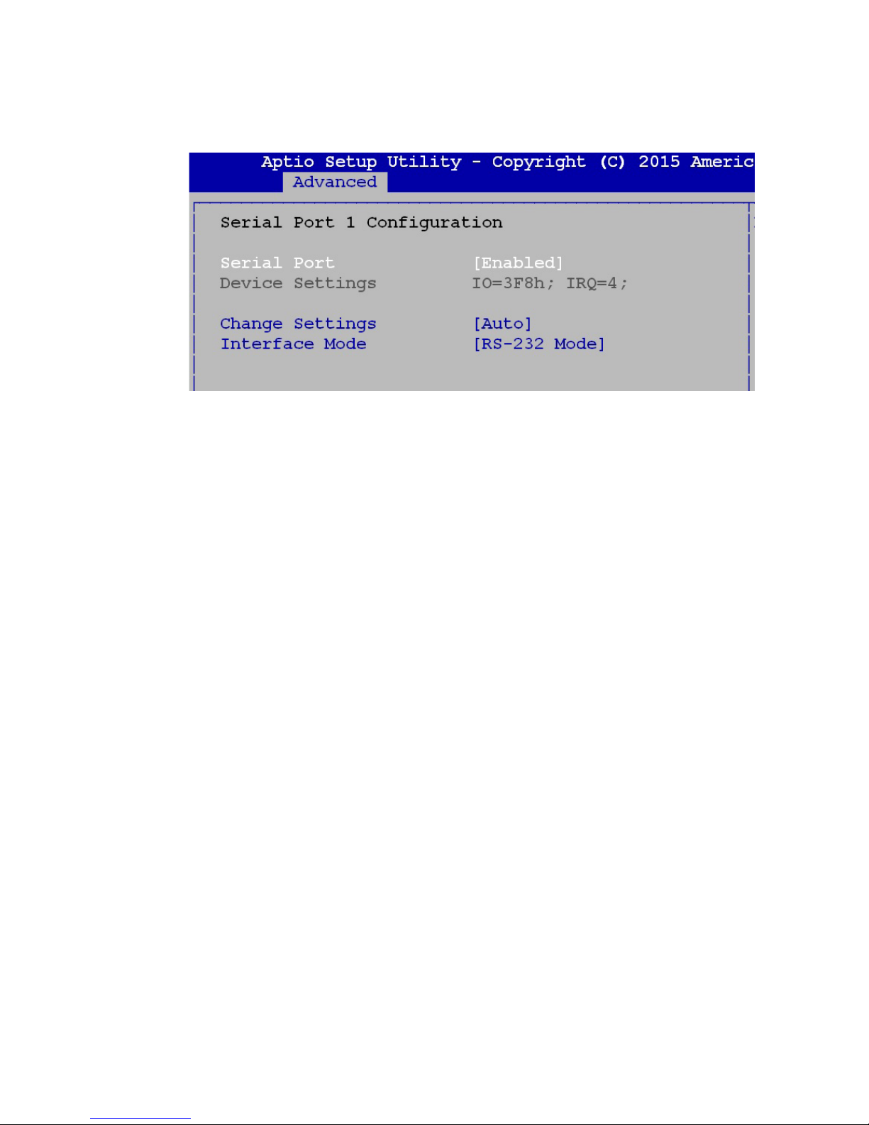
4.3.5 Serial Port 1 Conguration
Serial Port
Enable or Disable Serial Port.
Device Setting
Current IO address and interrupt resource of Serial Port.
Change Settings
Select another device setting.
There are 6 options as follow :
• Auto
• IO=3F8h; IRQ=4;
• IO=3F8h; IRQ=3,4,12;
• IO=2F8h; IRQ=3,4,12;
• IO=3E8h; IRQ=3,4,12;
• IO=2E8h; IRQ=3,4,12;
Interface Mode
There are 3 options as follow :
• RS-232 Mode
• RS-422 Mode
• RS-485 Mode
Figure 4-3-5: Serial Port 1 Setup screen
Page 61
54
BIOS AND DRIVER SETTING
©Vecow MTC-4021 User Manual
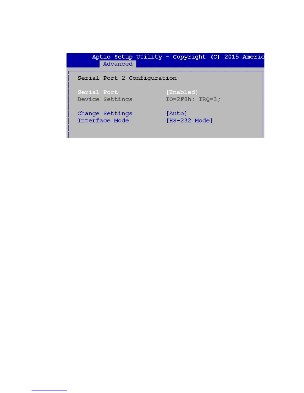
4.3.6 Serial Port 2 Conguration
Serial Port
Enable or Disable Serial Port.
Device Setting
Current IO addresses and interrupts resource of Serial Port.
Change Settings
Select another device setting.
There are 6 options as follow :
• Auto
• IO=2F8h; IRQ=3;
• IO=3F8h; IRQ=3,4,12;
• IO=2F8h; IRQ=3,4,12;
• IO=3E8h; IRQ=3,4,12;
• IO=2E8h; IRQ=3,4,12;
Interface Mode
There are 3 options as follow :
• RS-232 Mode
• RS-422 Mode
• RS-485 Mode
Figure 4-3-6 : Serial Port 2 Setup screen
Page 62
55
BIOS AND DRIVER SETTING
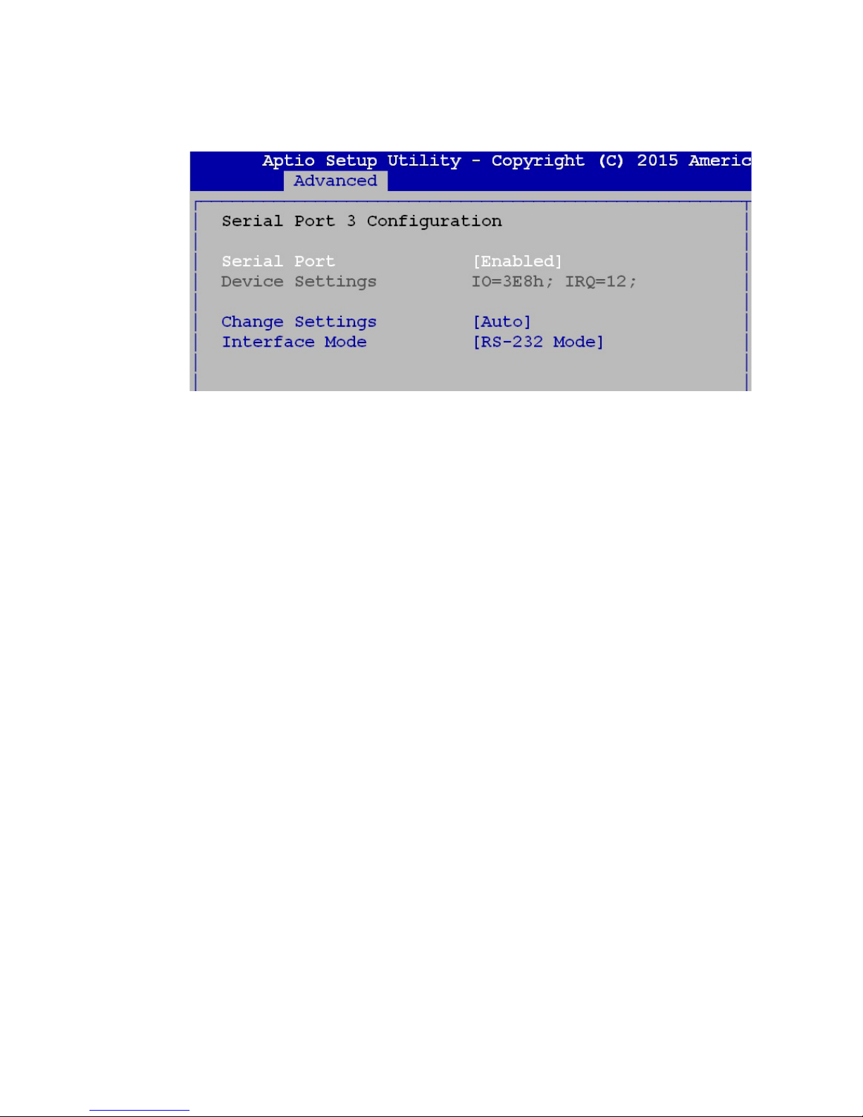
4.3.7 Serial Port 3 Conguration
Serial Port
Enable or Disable Serial Port.
Device Setting
Current IO address and interrupt resource of Serial Port.
Change Settings
Select another device setting.
There are 6 options as follow :
• Auto
• IO=3E8h; IRQ=12;
• IO=3E8h; IRQ=3,4,12;
• IO=2E8h; IRQ=3,4,12;
• IO=2F0h; IRQ=3,4,12;
• IO=2E0h; IRQ=3,4,12;
Interface Mode
There are 3 options as follow :
• RS-232 Mode
• RS-422 Mode
• RS-485 Mode
Figure 4-3-7: Serial Port 3 Setup screen
Page 63
56
BIOS AND DRIVER SETTING
©Vecow MTC-4021 User Manual
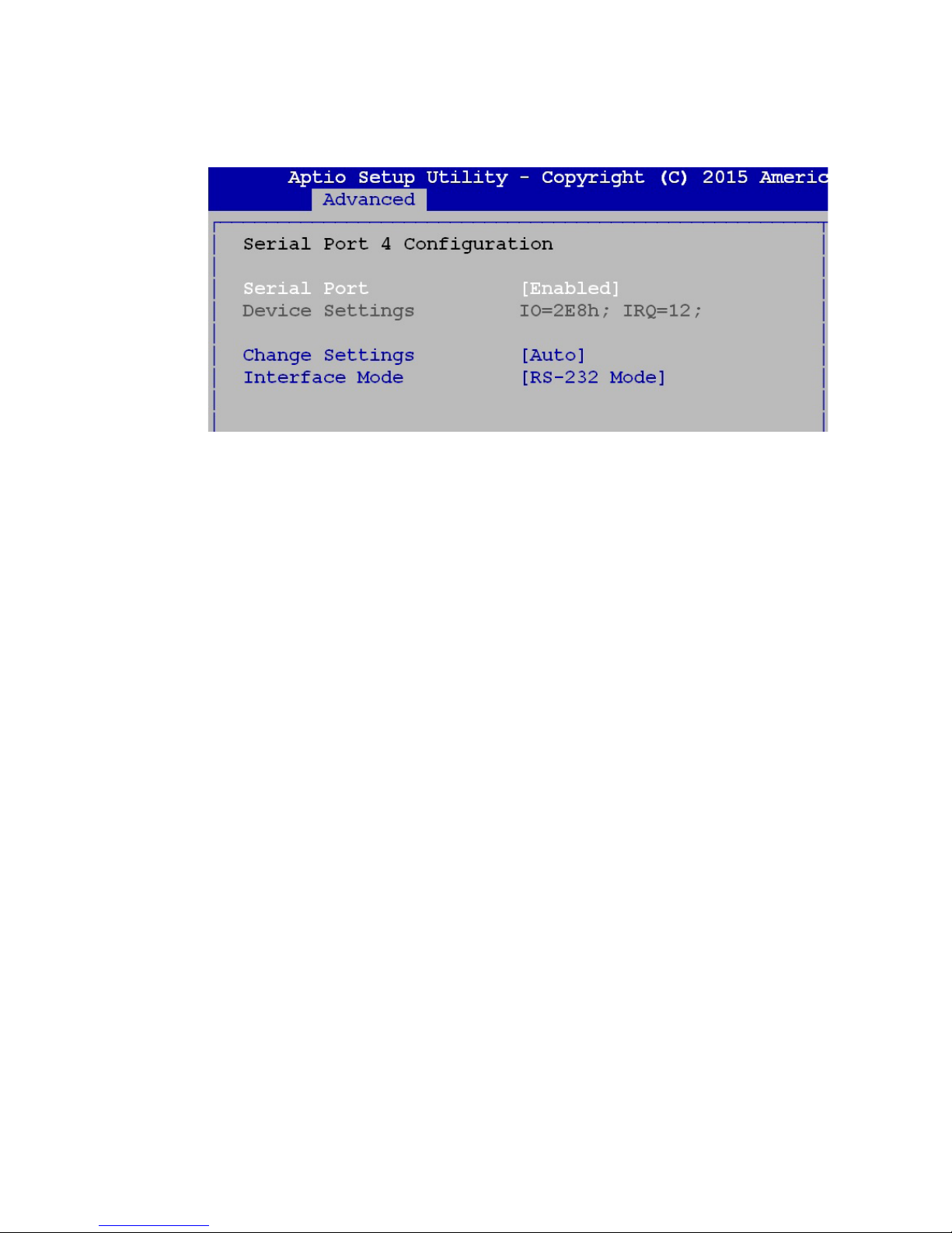
4.3.8 Serial Port 4 Conguration
Serial Port
Enable or Disable Serial Port.
Device Setting
Current IO address and interrupt resource of Serial Port.
Change Settings
Select another device setting.
There are 6 options as follow :
• Auto
• IO=2E8h; IRQ=12;
• IO=3E8h; IRQ=3,4,12;
• IO=2E8h; IRQ=3,4,12;
• IO=2F0h; IRQ=3,4,12;
• IO=2E0h; IRQ=3,4,12;
Interface Mode
There are 3 options as follow :
• RS-232 Mode
• RS-422 Mode
• RS-485 Mode
Figure 4-3-8: Serial Port 4 Setup screen
Page 64
57
BIOS AND DRIVER SETTING
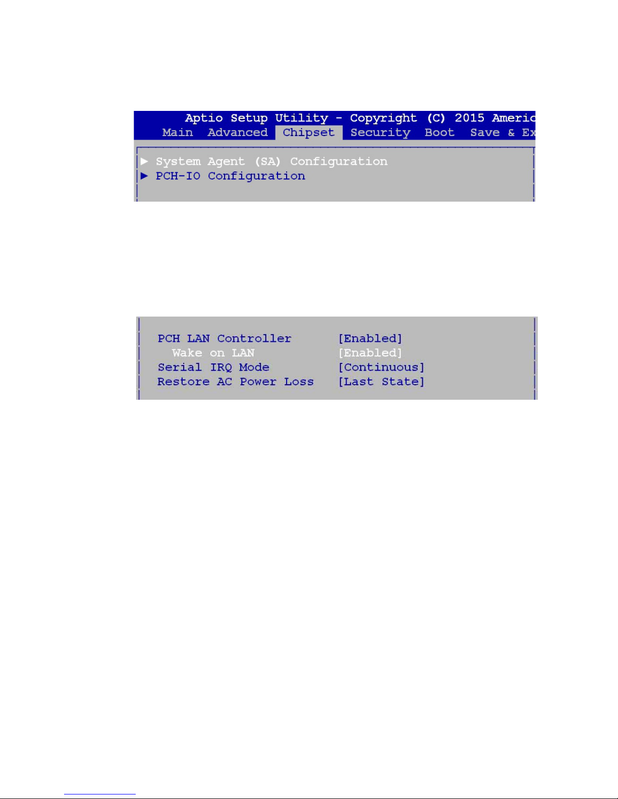
4.4 Chipset Function
4.4.1 WOL Conguration
PCH LAN Controller
Enable or Disable on board network device.
Wake on LAN
Enable or Disable integrated LAN to wake the system.
Figure 4-4-1 : Network Setup screen
Figure 4-4: Chipset Function Setup screen
Page 65
58
BIOS AND DRIVER SETTING
©Vecow MTC-4021 User Manual
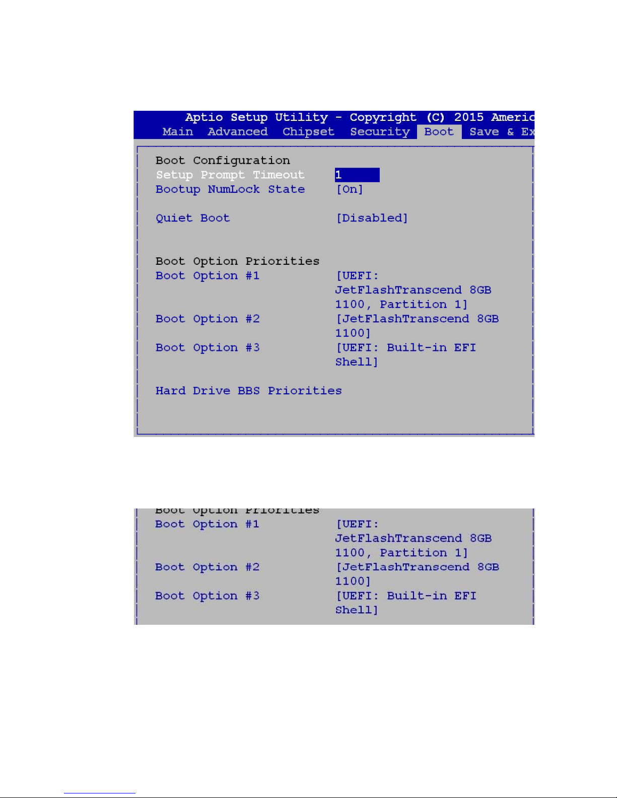
4.5.1 Boot Option
Boot option
You can select boot device priority in this page.
Figure 4-5-1 Boot Option Setup screen
4.5 Boot Function
Figure 4-5: Boot function Setup screen
Page 66
59
BIOS AND DRIVER SETTING
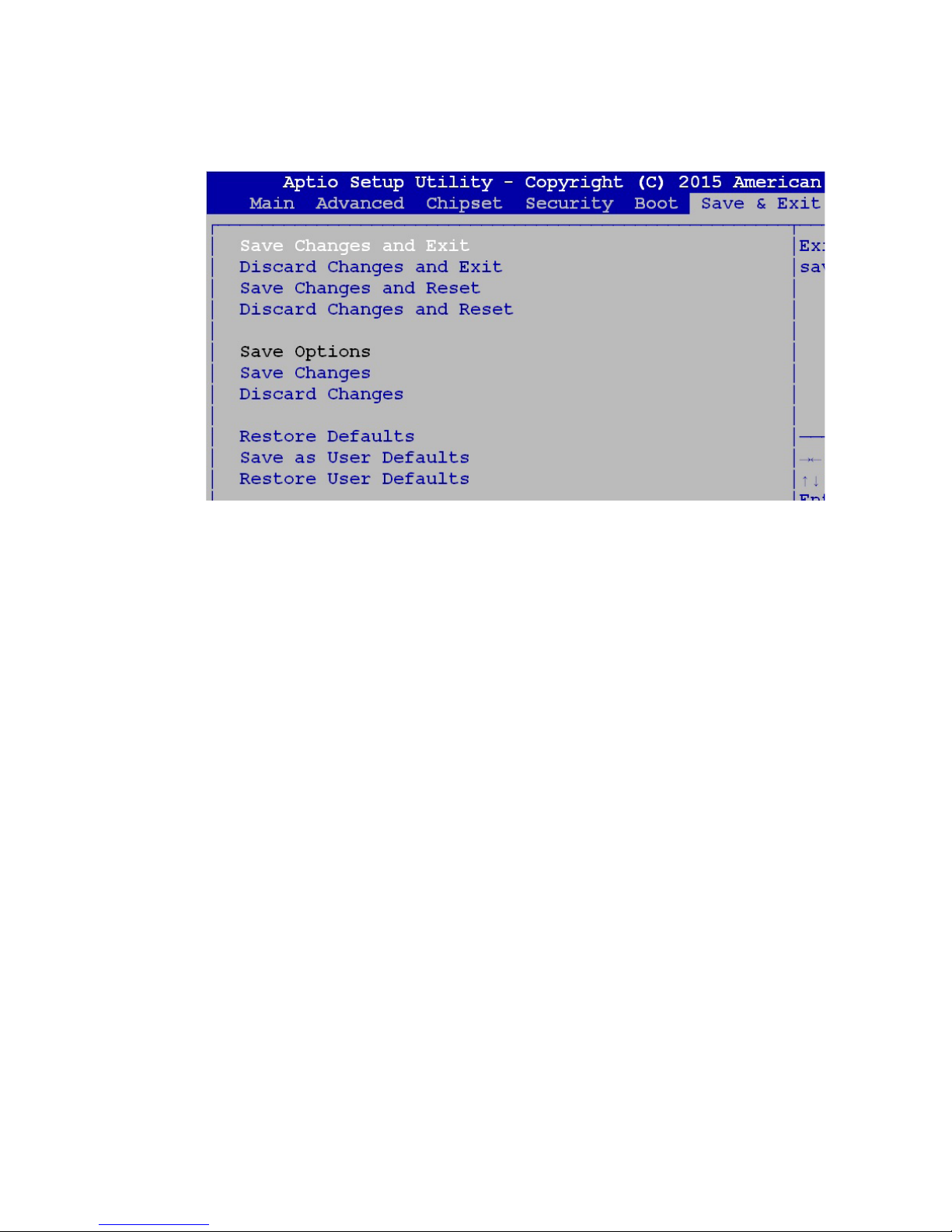
4.6 Save & Exit
Figure 4-6 Save & Exit Setup screen
Save Changes and Exit / Save Changes and Reset
Choose this setting to exit the BIOS setup program and save changes to
the BIOS NVRAM memory. Make sure you select this in order to keep your
changes.
Discard Changes and Exit / Discard Changes and Reset
Choose this setting to exit the BIOS SETUP program discarding all changes
made.
Page 67
60
©Vecow MTC-4021 User Manual
Appendix A
A
A.1 I/O Pin Denition
I/O Pin Base Adr Usage
GPIO 10~17 0xA00 CN16-GPIO
GPIO 20~27 0xA01 DIO Output
GPIO 30~37 0xA02 -----------
GPIO 40~47 0xA03 -----------
GPIO 50~57 0xA04 DIO Input
GPIO 60~67 0xA05 CN16-GPIO
APPENDIX A : ISOLATED DIO GUIDE
A.2 Function Description
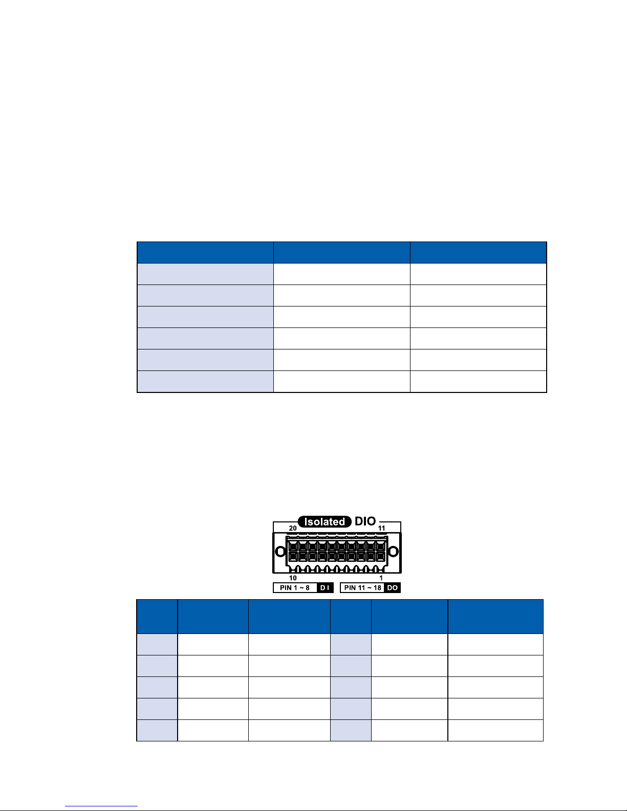
The ECS-4000 offers a 16-bit DIO (8-DI/ 8-DO) 20-pin terminal block connector.
Each bit of DI and DO equipped with a photo-coupler for isolated protection.
All I/O pins are xed by Hardware design and cannot change in/out direction in
runtime process. The denition is listed as follows:
Pin
No.
Denition Description
Pin
No.
Denition Description
1 EXT_IN0 GPIO Input 0 11 EXT_OUT0 GPIO Output 0
2 EXT_IN1 GPIO Input 1 12 EXT_OUT1 GPIO Output 1
3 EXT_IN2 GPIO Input 2 13 EXT_OUT2 GPIO Output 2
4 EXT_IN3 GPIO Input 3 14 EXT_OUT3 GPIO Output 3
5 EXT_IN4 GPIO Input 4 15 EXT_OUT4 GPIO Output 4
Page 68
61
Appendix A
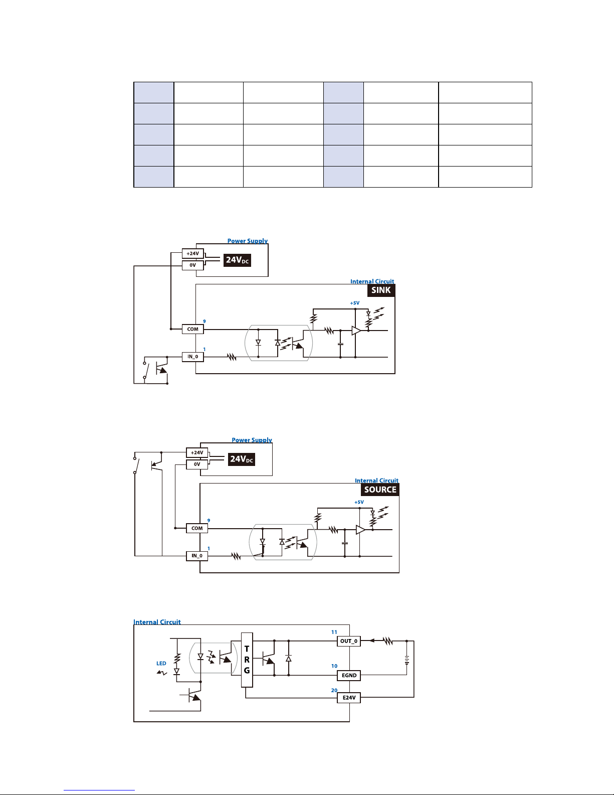
Signal Circuit of Input NPN
Digital GPIO input signal circuit in SINK mode (NPN) is illustrated as follow.
Signal Circuit of Input PNP
Digital GPIO input signal circuit in SOURCE mode (PNP) is illustrated as follow.
Signal Circuit of Output NPN
Digital GPIO output signal circuit in SINK mode (NPN) is illustrated as follow.
6 EXT_IN5 GPIO Input 5 16 EXT_OUT5 GPIO Output 5
7 EXT_IN6 GPIO Input 6 17 EXT_OUT6 GPIO Output 6
8 EXT_IN7 GPIO Input 7 18 EXT_OUT7 GPIO Output 7
9 DI_COM GPIO COM 19 Reserved NC
10 EGND GPIO GND 20 E24V External 24V DC
Page 69
62
©Vecow MTC-4021 User Manual
Appendix B
A.3 Software Package
There are 2 folders inside :
1. Driver Folder
2. DIO Demo Tool Folder
A.4 Driver Installing
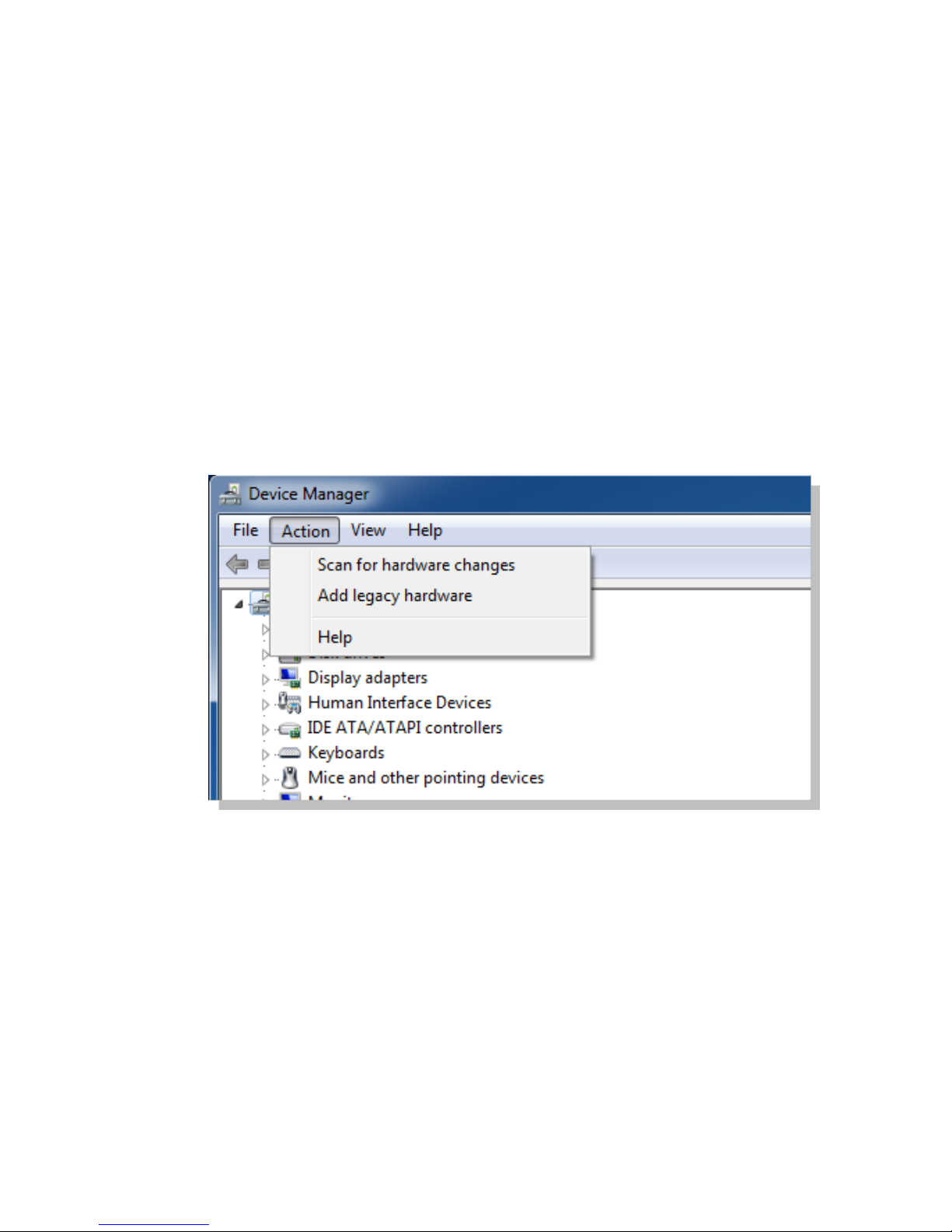
Supports Windows 8.1 and Windows 7. Please do make sure your OS version
before installing.
Please select “Add legacy hardware” on device management
Page 70

63
Appendix B
B
APPENDIX B : GPIO and WDT Functions
B.1 Function Description
The WDT are using internal Super I/O function. However, you must entry super
I/O conguration mode to set it.
Super I/O special address port = 0x2E
Super I/O special data port = 0x2F
GPIO Logical device is 0x07
B.2 Entry Functions
WDT_TimeOut_MSB,SPECIAL WDT_TimeOut_LSB,SPECIAL
1. Entry MB PnP Mode.
//write twice 0x87 value.
outportb(Super I/O special address port, 0x87);
outportb(Super I/O special address port, 0x01);
outportb(Super I/O special address port, 0x55);
outportb(Super I/O special address port, 0x55);
2. Located on Logical Device 7(LOGIC_DEVICE_WDT)
//write 0x07 on Reg [0x07] , this setup must follow Step A. that can be workable.
outportb(Super I/O special address port, 0x07);
outportb(Super I/O special data port, 0x07);
3. Cong the WDT Register
outb(WDT_Cong,SPECIAL_ADDRESS_PORT);
outb(WDT_As_Second|WDT_Pin_PWRGD,SPECIAL_DATA_PORT);
4. Start WDT TimeOut Value
Here have 2 Byte for WDT timing count, MSB and LSB should be write the
value separate.
outb(WDT_TimeOut_LSB,SPECIAL_ADDRESS_PORT);
outb(WDT_TimeOutValue,SPECIAL_DATA_PORT);
Page 71
64
©Vecow MTC-4021 User Manual
Appendix C
C
APPENDIX C : Power Consumption
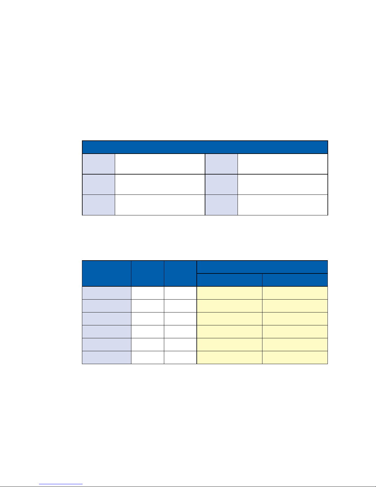
ECS-4000 Power Consumption Testing :
Power Source :
CPU RAM
Input
Power
Standby Mode
Max Current Max Consumption
i7-5650U 4GB X 2 06V 0.330A 01.98W
i7-5650U 4GB X 2 09V 0.227A 02.04W
i7-5650U 4GB X 2 12V 0.190A 02.28W
i7-5650U 4GB X 2 24V 0.215A 05.16W
i7-5650U 4GB X 2 28V 0.192A 05.38W
i7-5650U 4GB X 2 36V 0.137A 04.93W
ECS-4000
Storage-
CFast
N/A
Aux card
1
N/A
Storage-
SATA 0
Transcend SSD370 SATA
SSD 64GB
Aux card
2
N/A
Storage-
SATA 1
N/A
Power
Source
Chroma 62006P-100-25
Page 72
65
Appendix C
CPU
Power-on and boot to Win7 64-bit
Idle Status :
CPU usage less 3%
Run 100% CPU usage
Max
Current
Max
Consumption
Max
Current
Max
Consumption
i7-5650U 2.200A 13.20W 3.600A 21.60W
i7-5650U 1.430A 12.87W 2.250A 20.25W
i7-5650U 1.070A 12.84W 1.610A 19.32W
i7-5650U 0.610A 14.64W 0.900A 21.60W
i7-5650U 0.530A 14.84W 0.760A 21.28W
i7-5650U 0.430A 15.48W 0.610A 21.96W
Page 73

For further support information, please visit www.vecow.com
This document is released for reference purpose only.
All product offerings and specications are subject to change without prior notice.
No part of this publication may be reproduced in any form or by any means, electric, photocopying, recording or
otherwise, without prior authorization of the publisher.
The rights of all the brand names, product names and trademarks belong to their respective owners.
© Vecow Co., Ltd. 2016. All rights reserved.
 Loading...