

Vecow MTC-2021 User Manual

USER
Manual
USER
Manual
1.0.0 Edition 20150324
MTC-2021
21.5” Fanless Multi-Touch Computer
ii
Version Date Page Description Remark
0.9 03/06/2015 All Preliminary Release
1.0 03/24/2015 All Ofcal Release
Record of Revision

iii
This manual is released by Vecow Co., Ltd. for reference purpose only. All
product offerings and specications are subject to change without prior notice. It
does not represent commitment of Vecow Co., Ltd. Vecow shall not be liable for
direct, indirect, special, incidental, or consequential damages arising out of the
use of the product or documentation, nor for any infringements upon the rights
of third parties, which may result from such use.
This equipment has been tested and found to comply with the limits for a Class
A digital device, pursuant to part 15 of the FCC Rules. These limits are designed
to provide reasonable protection against harmful interference when the
equipment is operated in a commercial environment. This equipment generates,
uses, and can radiate radio frequency energy and, if not installed and used in
accordance with the instruction manual, may cause harmful interference to radio
communications. Operation of this equipment in a residential area is likely to
cause harmful interference in which case the user will be required to correct the
interference at his own expense.
FCC
The product (s) described in this manual complies with all applicable European
Union (CE) directives if it has a CE marking. For computer systems to
remain CE compliant, only CE-compliant parts may be used. Maintaining CE
compliance also requires proper cable and cabling techniques.
CE
This document contains proprietary information protected by copyright. No part
of this publication may be reproduced in any form or by any means, electric,
photocopying, recording or otherwise, without prior written authorization
by Vecow Co., Ltd. The rights of all the brand names, product names and
trademarks belong to their respective owners.
Declaimer
Declaration of Conformity
Copyright and Trademarks
iv
Part Number Description
MTC-2021 21.5” Fanless Multi-Touch Computer with Intel® Bay Trail
Quad-Core E3845 Processor
Order Information
Part Number Description
DDR3L8G Certied DDR3L 8G RAM
DDR3L4G Certied DDR3L 4G RAM
PWA-60WP3B 60W, 24V/2.5A 100V AC to 240V AC Power Adapter for 3 Pin 5.0mm
Terminal Block
Panel-Mount Panel mount Kit
VESA-Mount VESA Table Stand
WiFi Module Mini PCIe WiFi Module with Antenna
3G Module Mini PCIe 3G/GPS Module with Antenna
4G Module Mini PCIe 4G/GPS Module with Antenna
Order Accessories

v
Table of Contents
CHAPTER 1 GENERAL INTRODUCTION 1
1.1 Overview 1
1.2 Features 1
1.3 Product Specication 2
1.4 Mechanical Dimension 4
CHAPTER 2 GETTING TO KNOW YOUR MTC-2021 5
2.1 Packing List 5
2.2 I/O Functions 6
2.2.1 External I/O Connectors 6
2.2.2 Reset Tact Switch 6
2.2.3 Power Button 7
2.2.4 PWR & HDD LED Indicators 7
2.2.5 VGA Connector 8
2.2.6 HDMI Connector 9
2.2.7 Dual USB 2.0 9
2.2.8 10/100/1000 Mbps LAN Port 10
2.2.9 Audio Connector 11
2.2.10 8-bit GPIO 11
2.2.11 Serial Port COM 1/ COM 2 12
2.2.12 Serial Port COM 3/ COM 4 13
2.2.13 Isolated Serial Port COM 5/ COM 6 14
2.2.14 DC-in 9V to 28V Terminal Block 15
2.2.15 USB 3.0 Ports 15
2.3 Mainboard Expansion Connector 16
2.3.1 Panel Miscellaneous Pin Header 17
2.3.2 CN24, CN25, J2 LVDS 18
2.3.3 CN21 SATA II Connector, J1 SATA Power Connector 20
2.3.4 CN23 mSATA Connector 22
2.3.5 CN20, CN22 Mini PCIe Connector 24
2.3.6 Battery 26
2.4 Jumper Setting 27
2.4.1 JP1(A) CMOS Clear Jumper Setting 28
2.4.2 JP1(B) ME Clear Jumper Setting 28
2.4.3 JP2 LVDS Panel Power Selection 29

vi
CHAPTER 3 HARDWARE INSTALLATION 30
3.1 How to Open Your MTC-2021 Chassis 30
3.2 Install DDR3L SO-DIMM Modules 32
3.3 Install SSD/ HDD 33
3.4 Install Mini PCIe Module 35
3.5 Install WiFi Module and Antenna 36
3.6 Mount Your MTC-2021 40
CHAPTER 4 BIOS AND DRIVER SETTING 42
4.1 BIOS Settings 42
4.2 Main Menu 43
4.3 Advanced Function 44
4.3.1 ACPI Setting 44
4.3.2 Serial Port 1 Conguration 45
4.3.3 Serial Port 2 Conguration 46
4.3.4 Serial Port 3 Conguration 47
4.3.5 Serial Port 4 Conguration 48
4.3.6 Serial Port 5 Conguration 49
4.3.7 Serial Port 6 Conguration 50
4.3.8 PPM Conguration 51
4.3.9 CPU Conguration 52
4.3.10 IDE Conguration 53
4.4 Chipset Function 54
4.4.1 Display Conguration 54
4.4.2 Power Loss Conguration 54
4.5 Boot Function 55
4.6 Save & Exit 55
APPENDIX A GPIO AND WDT 56
A.1 Super I/O Denition 56
A.2 GPIO and WDT Setup 57

1
GENERAL INTRODUCTION
1
GENERAL INTRODUCTION
MTC-2021 is an ultra-compact 21.5” 1920x1080 Full HD fanless 10-Point MultiTouch Panel Computer for industrial grade applications. With ultra-low power
consumption quad core Intel
®
Atom™ E3845 CPU engine, single DDR3L SODIMM supports up to 8GB memory, VGA/ HDMI display output, built-in dual
GbE LAN, 1 USB 3.0, 2 USB 2.0, 6 COM, 8 GPIO, 9V to 28V DC-in, MTC-2021
ts in slim mechanical design, just so thin in 4.3 cm only.
Advanced glove-working 10-Point Projected Capacitive Touch Technology,
7H Hardness LCD Panel, 21.5” 16:9 1920x1080 Full HD LCD Panel with LED
Backlight management, optional supports IP65 Front Panel Protection, MTC2021 integrates advanced multi-touch features, excellent graphics performance
and outstanding reliability.
With excellent performance, ultra-slim size and trusted reliability, MTC-2021
is your great choice for Intelligent Manufacturing System, Environmental
Monitoring, Point-of-Information, Point-of-Sales, Self-service Kiosk,
Transportation, Internet of Things (IoT) or any HMI applications.
1.1 Overview
1.2 Features
• Intel® Atom™ Quad Core E3845 1.91GHz Processor
• Fanless, Ultra-compact, 4.3 cm Slim Design
• 7H Hardness Anti-scratch Surface
• Touch Screen Works with Gloves
• 10-point Touch Screen (Projected Capacitive)
• 21.5” 16:9 Full HD (1920x1080) LCD Panel with LED Backlight
• 9V to 28V DC Power Input
• 2 GbE LAN, 1 USB 3.0, 2 USB 2.0, 8 GPIO
• 6 COM Ports Including 2 Isolated RS-232/ 422/ 485
• Mounting Methods: Panel/ VESA
• IP65 Front Panel Protection (Optional)
• Supports 3G/ 4G/ GPS/ GPRS/ WiFi/ Bluetooth (Optional)
• Sunlight Readability Requirements (Optional)
2
GENERAL INTRODUCTION
©Vecow MTC-2021 User Manual
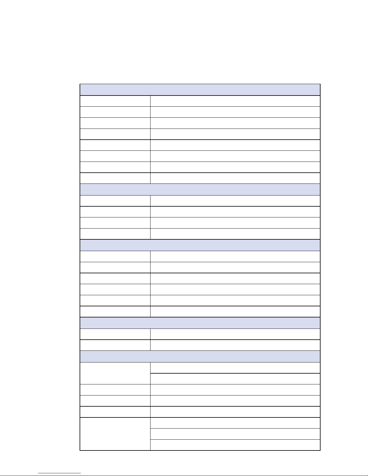
1.3 Product Specication
1.3.1 Specications of Vecow MTC-2021
Display Panel
Type a-Si TFT-LCD
Size 21.5" (16:9)
Resolution 1920 x 1080 (Full HD)
Display Color 16.7 M (RGB 8 bits)
Backlight LED
Brightness (cd/m
2
) 250 (Optional up to 1200)
Viewing Angles 89/ 89/ 89/ 89 (L/ R/ U/ D)
Contrast Ratio 3000:1
Touch Screen
Type 10-point Projected Capacitive
Transparency ≥ 85%
Surface Hardness 7H
Control Interface USB
System
Processor Intel® Atom™ Quad Core E3845 1.91GHz Processor
Chipset Intel
®
SoC
Memory 1 DDR3L 1333 SO-DIMM, up to 8GB
Video VGA/ HDMI Output
Audio 1 Mic-in, 1 Line-out
Software Support Windows 8, Windows 7, WES7, Linux
Storage
SATA 1 SATA II (3Gbps)
mSATA 1 mSATA (Mini PCIe Type)
I/O Ports
Serial 6 COM (2 RS-232, 4 RS-232/ 422/ 485)
2 Isolated RS-232/ 422/ 485 with 5kV DC
Ethernet 2 Gigabit LAN by Intel
®
WG82574L
USB 1 USB 3.0, 2 USB 2.0
GPIO 8 GPIO
Mini PCIe 1 Mini PCIe Socket (PCIe + USB + SIM Card Socket)
1 Mini PCIe Socket (PCIe + USB)
1 mSATA Socket
3
GENERAL INTRODUCTION
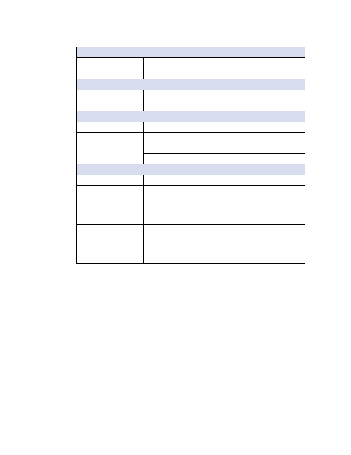
Others
Watchdog Timer Reset : 1 to 255 sec./min. per step
GPS Onboard GPS Module (Optional)
Power
Power Input 3-pin Terminal Block; DC-in 9V to 28V
Adapter AC to DC, 60W (Optional)
Mechanical
Dimensions (WxHxD) 537.6mm x 329.06mm x 42.6mm (21.2" x 13" x 1.7")
Weight 5.8 kg (12.8 lb)
Mounting VESA Mount (75mm x 75mm, 100mm x 100mm)
Panel Mount
Environment
Operating Temperature 0°C to 50°C (32°F to 122°F)
Storage Temperature -20°C to 60°C (-4°F to 140°F)
Humidity 5% to 90%, non-condensing
Vibration IEC 60068-2-64
Non-operation : 1.5 Grms , 10Hz to 200Hz, 30 mins 3 Axis
Shock IEC 60068-2-27
20G, Half-sine, 11ms
Ingress Protection Front IP65 Water and Dust Proof (Optional)
EMC CE, FCC
4
GENERAL INTRODUCTION
©Vecow MTC-2021 User Manual
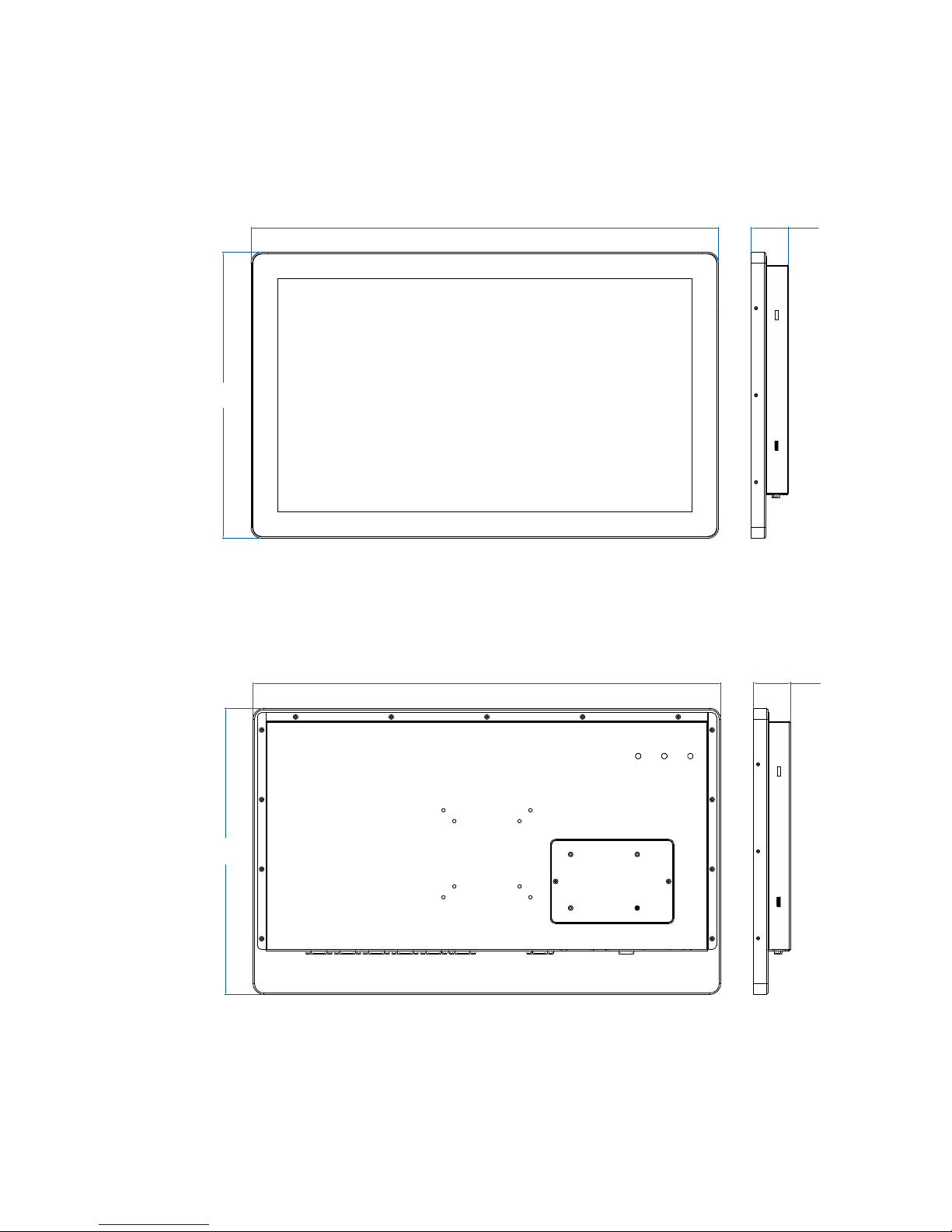
1.4 Mechanical Dimension
1.4.1 MCT-2021 Front View
537,60
(21,2)
42,60
(1,7)
329,0
(13.0)
Unit: mm (inch)
1.4.2 MTC-2021 Rear View
537,60
(21,2)
42,60
(1,7)
329,0
(13,0)
Unit: mm (inch)
5
GETTING TO KNOW YOUR MTC-2021
2
GETTING TO KNOW YOUR MTC-2021
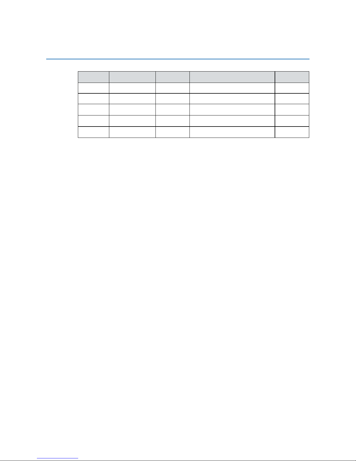
2.1 Packing List
Item Description Qty
1 MTC-2021, 21.5” Fanless Multi-Touch Computer
(According to the conguration you order, the MTC-2021
may contain SSD/HDD and DDR3L SO-DIMM. Please verify
these items if necessary.)
1
2 Accessory box, which contains
● Vecow Drivers & Utilities DVD
● 3-pin pluggable terminal block
● FH M3x4 screws for HDD
● BH M2.5x6 screws for Mini PCIe
1
1
4
6
6
GETTING TO KNOW YOUR MTC-2021©Vecow MTC-2021 User Manual
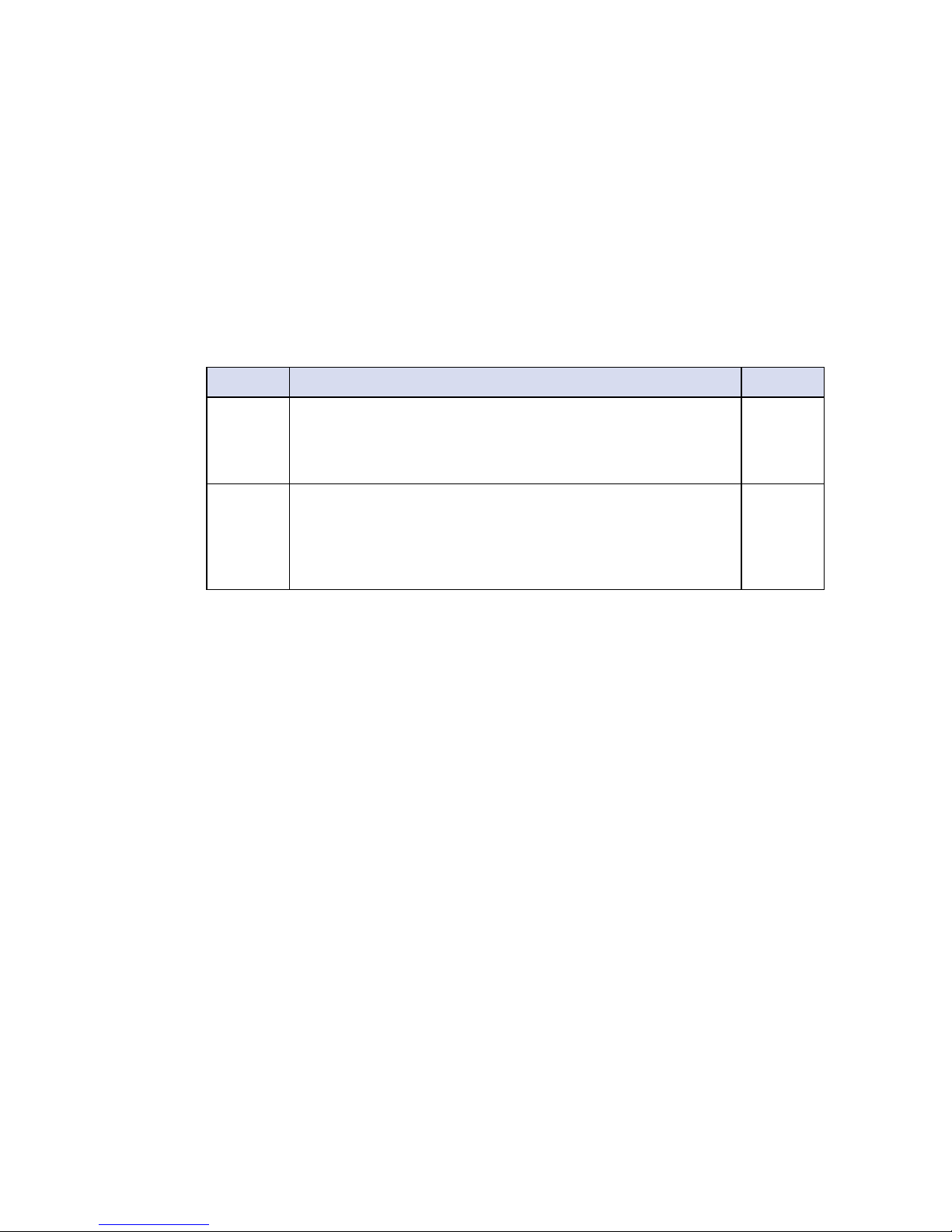
2.2.1 External I/O Connectors
2.2 I/O Functions
HDMI
2.2.2 Reset Tact Switch
It is a hardware reset switch. Use this switch to reset the system without turning
off the power. Momentarily pressing the switch will reset the MTC-2021.
7
GETTING TO KNOW YOUR MTC-2021
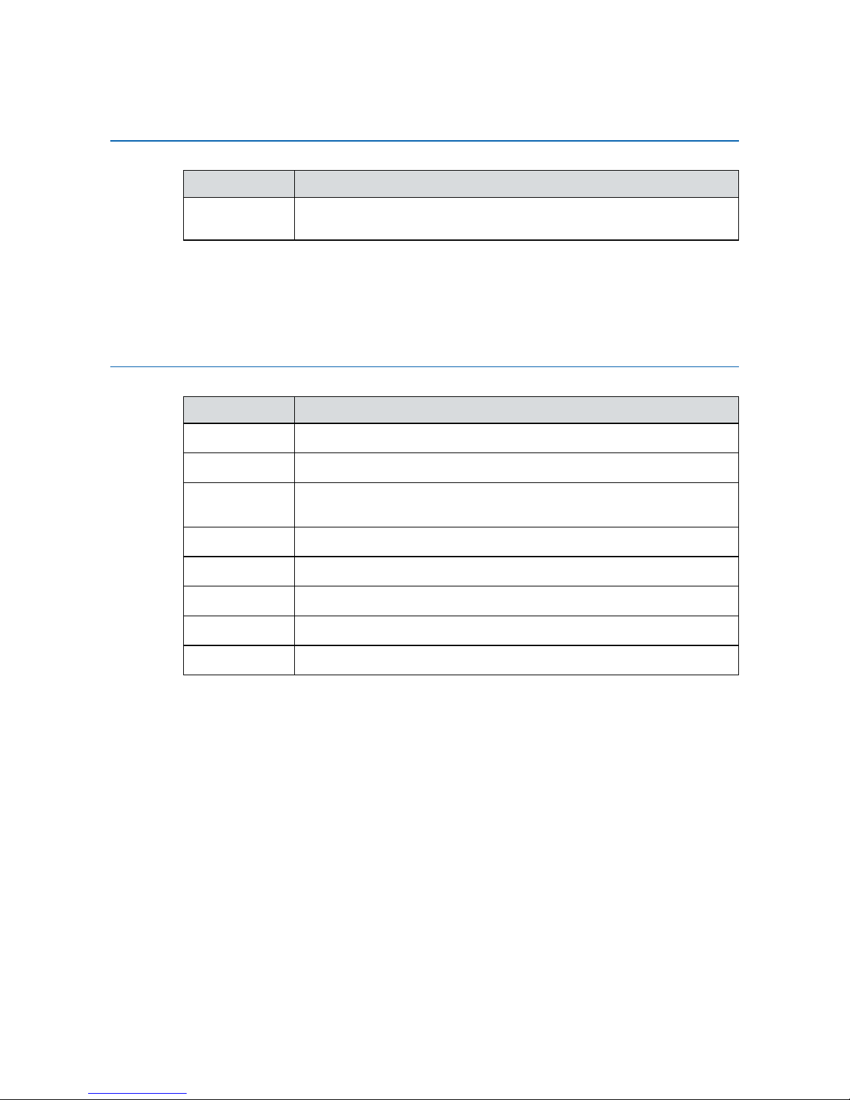
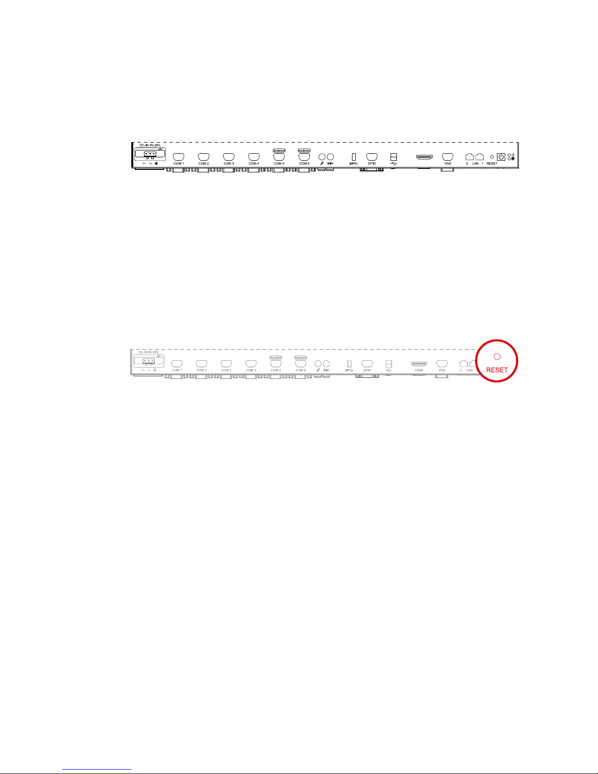
2.2.3 Power Button
The power button is a non-latched switch with dual color LED (Blue/ Orange) for
status monitoring : S0, S3 and S5. LED indications of system status are listed
as follow :
To turn on the MTC-2021, press the power button and the blue LED is lighted
up. To turn off the MTC-2021, you can either issue a shutdown command in OS,
or just simply press the power button. In case of system halts, you can press
and hold the power button for 4 seconds to compulsorily shut down the system.
Please note that a 4 seconds interval is kept by the system between two on/
off operations (i.e. once turning off the system, you shall wait for 4 seconds to
initiate another power-on operation).
Status LED Displayed System Situation
S0 Blue System working
S3, S5 Orange Suspend to RAM, System off with standby power
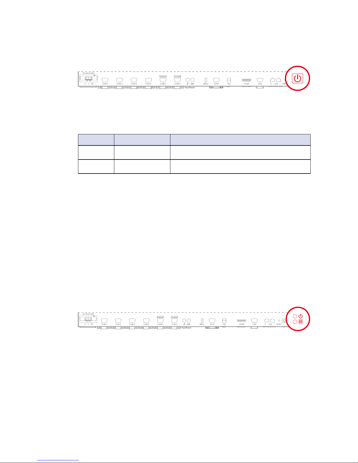
2.2.4 PWR & HDD LED Indicators
Yellow - HDD LED: A hard disk LED. If the LED is on, it indicates that the
system’s storage is functional. If it is off, it indicates that the system’s storage is
not functional. If it is ashing, it indicates data access activities.
Green - Power LED: If the LED is solid green, it indicates that the system is
powered on.
8
GETTING TO KNOW YOUR MTC-2021©Vecow MTC-2021 User Manual
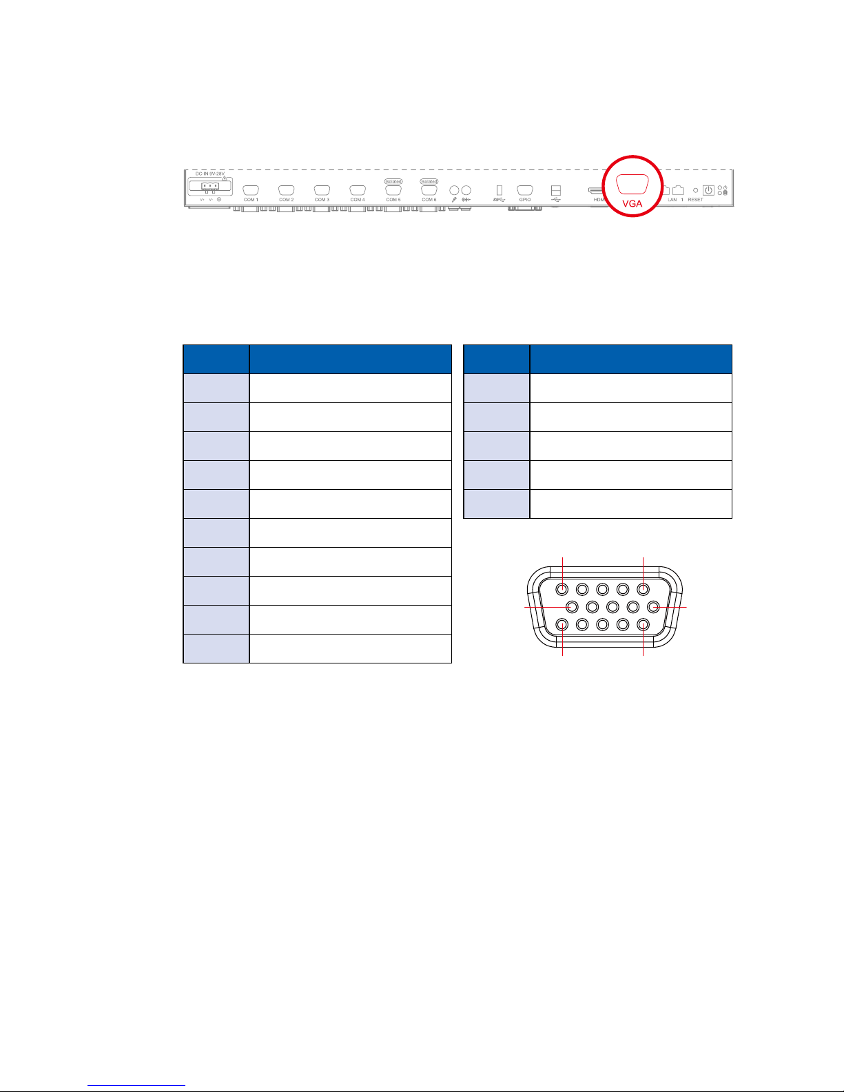
2.2.5 VGA Connector
The MTC-2021 comes with a DB15 female connector to connect a VGA monitor.
To ensure that the monitor image remains clear, be sure to tighten the monitor
cable after connecting it to the MTC-2021. The VGA output mode supports up
to 2560x1600 resolution. The pin assignments of the VGA connector are shown
below.
Pin No. Denition
1 Red Color Signal
2 Green Color Signal
3 Blue Color Signal
4 NC
5 Ground
6 VGA Detect
7 Ground
8 Ground
9 VCC
10 Ground
Pin No. Denition
11 NC
12 DDC-DATA
13 H-Sync.
14 V-Sync.
15 DDC-CLK
15
1115
610
9
GETTING TO KNOW YOUR MTC-2021
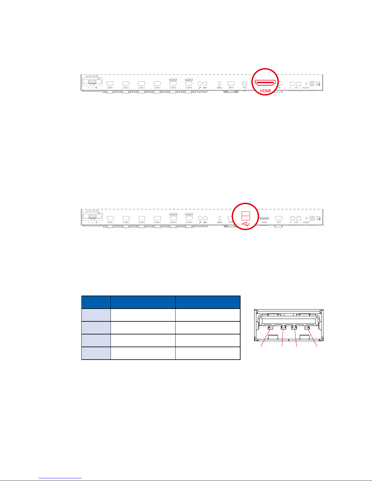
2.2.6 HDMI Connector
The HDMI output mode supports up to 2560x1600 resolution The HDMI mode
is automatically selected according to the display device connected.
2.2.7 Dual USB 2.0
The MTC-2021 comes with 2 USB 2.0 hosts. The USB interface supports Plug
and Play, which enables you to connect or disconnect a device whenever you
want, without turning off the system. The hosts can be used for an external ash
disk or hard drive for storing large amounts of data. You can also use these USB
hosts to connect to a keyboard or a mouse. The following diagram shows the
pinouts for USB 1 and USB 2 ports.
Pin No. USB 1 USB 2
1 +5V +5V
2 USB 1- USB 2-
3 USB 1+ USB 2+
4 GND GND
1 2 3 4
10
GETTING TO KNOW YOUR MTC-2021©Vecow MTC-2021 User Manual
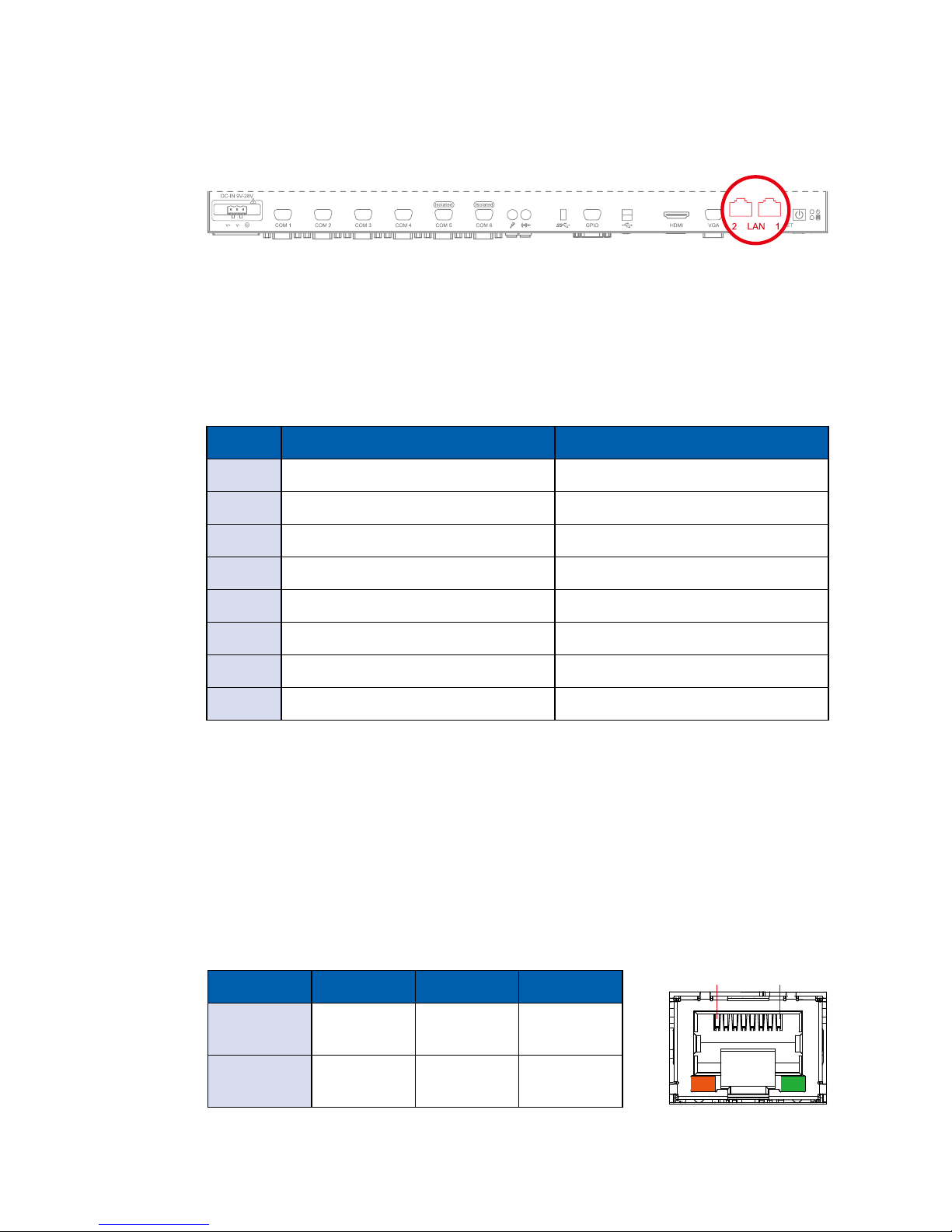
2.2.8 10/100/1000 Mbps LAN Port
There are two 10/100/1000 Mbps Ethernet LAN ports equipped with 8-pin RJ45 connector. LAN 1 and LAN 2 are powered by Intel 82574L chipset. Using
suitable RJ-45 cable, you can connect MTC-2021 system to a computer, or to
any other piece of equipment that has an Ethernet connection, for example,
a hub or a switch. Moreover, both of them have Wake-on-LAN and Pre-boot
Execution Environment capabilities. The following diagram shows the pinouts
for LAN 1 and LAN 2.
Pin No. 10 / 100 Mbps 1000 Mbps
1 E_TX+ MDI0_P
2 E_TX- MDI0_N
3 E_RX+ MDI1_P
4 ---- MDI2_P
5 ----- MDI2_N
6 E_RX- MDI1_N
7 ----- MDI3_P
8 ------ MDI3_N
1 8
The Ethernet ports use standard RJ-45 jack connectors with LED indicators to
show Active/ Link status and Speed status.
The LED indicators on the right bottom corners glow a solid green color when
the cable is properly connected to a 100 Mbps Ethernet network. The LED
indicator on the left bottom corner will ash on and off when Ethernet packets
are being transmitted or received.
The LED indicators on the right bottom corners glow a solid orange color when
the cable is properly connected to a 1000 Mbps Ethernet network. The LED
indicator on the left bottom corner will ash on and off when Ethernet packets
are being transmitted or received.
10 Mbps 100 Mbps 1000 Mbps
Right
Bottom Led
Off Solid
Green
Solid
Orange
Left
Bottom Led
Flash
Yellow
Flash
Yellow
Flash
Yellow
11
GETTING TO KNOW YOUR MTC-2021
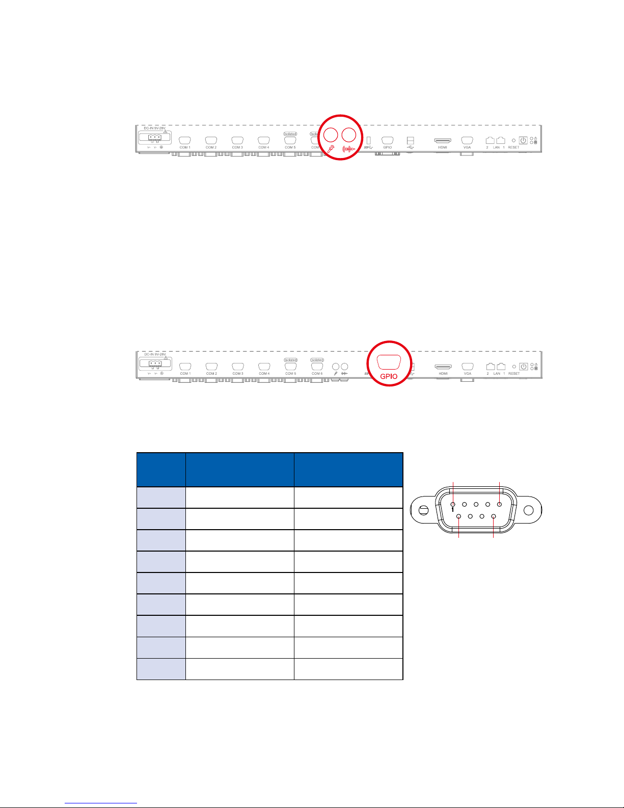
2.2.9 Audio Connector
The MTC-2021 offers stereo audio connector of Mic-in and Line-out. The
audio chip controller is by Realtek ALC892 which is compliant with the Intel
Azalia standard. To utilize the audio function in Windows, you need to install
corresponding drivers for Realtek ALC892 code.
2.2.10 8-bit GPIO
The MTC-2021 offers an 8-bit GPIO connector. Each bit internal pull up a weak
resistor to +V3.3_SB. Each bit can be congured for GPI or GPO. You can nd
the setting in BIOS.
Pin No. Denition Mapping to SIO
GPIO Function
1 GPIO 0 SIO_GPI70
2 GPIO 1 SIO_GPI71
3 GPIO 2 SIO_GPI72
4 GPIO 3 SIO_GPI73
5 GND GND
6 GPIO 4 SIO_GPI74
7 GPIO 5 SIO_GPI75
8 GPIO 6 SIO_GPI76
9 GPIO 7 SIO_GPI76
1 5
6 9
12
GETTING TO KNOW YOUR MTC-2021©Vecow MTC-2021 User Manual
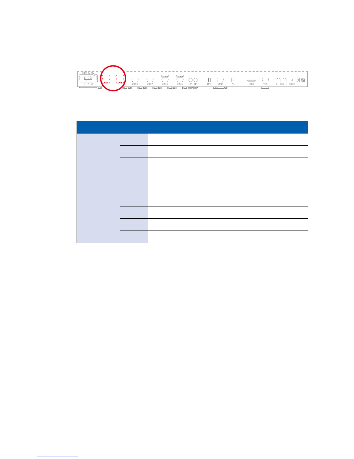
2.2.11 Serial Port COM 1/ COM 2
COM 1 and COM 2 are RS-232 only and provide up to 115,200 bps baud rate.
The pin assignments are shown in the table as follow.
Serial Port Pin No. RS-232
1,2
1 DCD
2 RXD
3 TXD
4 DTR
5 GND
6 DSR
7 RTS
8 CTS
9 RI
13
GETTING TO KNOW YOUR MTC-2021
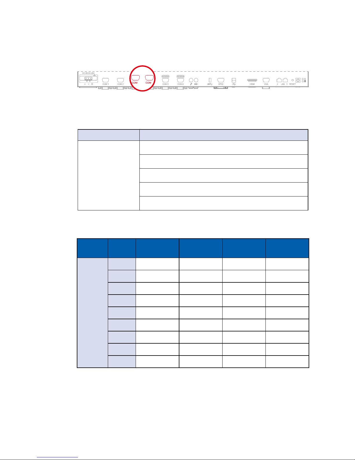
2.2.12 Serial Port COM 3/ COM 4
COM 3 and COM 4 can be congured for RS-232, RS-422, or RS-485 with auto
ow control communication. Serial Port 2 default setting is RS-232, if you want
to use RS-422 or RS-485, you can nd the setting in BIOS.
3 4
Serial
Port
Pin No. RS-232 RS-422
(5-wire)
RS-422
(9-wire)
RS-485
(3-wire)
3,4
1 DCD TXD- TXD- DATA-
2 RXD TXD+ TXD+ DATA+
3 TXD RXD+ RXD+ -----------
4 DTR RXD- RXD- -----------
5 GND GND GND GND
6 DSR ----------- RTS- -----------
7 RTS ----------- RTS+ -----------
8 CTS ----------- CTS+ -----------
9 RI ----------- CTS- -----------
The pin assignments are listed in the table as follow :
BIOS Setting Function
COM 3 / COM 4
RS-232
RS-422 (5-wire)
RS-422 (9-wire)
RS-485
RS-485 w/z auto-ow control
14
GETTING TO KNOW YOUR MTC-2021©Vecow MTC-2021 User Manual
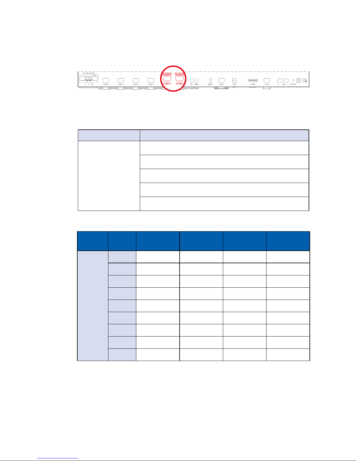
2.2.13 Isolated Serial Port COM 5/ COM 6
COM 5 and COM 6 can be congured for RS-232, RS-422, or RS-485 with auto
ow control communication. Serial Port 2 default setting is RS-232, if you want
to use RS-422 or RS-485, you can nd the setting in BIOS.
Serial
Port
Pin No. RS-232 RS-422
(5-wire)
RS-422
(9-wire)
RS-485
(3-wire)
5,6
1 DCD TXD- TXD- DATA-
2 RXD TXD+ TXD+ DATA+
3 TXD RXD+ RXD+ -----------
4 DTR RXD- RXD- -----------
5 GND GND GND GND
6 DSR ----------- RTS- -----------
7 RTS ----------- RTS+ -----------
8 CTS ----------- CTS+ -----------
9 RI ----------- CTS- -----------
The pin assignments are listed in the table as follow :
BIOS Setting Function
COM 5 / COM 6
RS-232
RS-422 (5-wire)
RS-422 (9-wire)
RS-485
RS-485 w/z auto-ow control
 Loading...