

Vecow IVH-9016-PoER820Q, IVH-9000-2R505M, IVH-9000-2R820Q, IVH-9016-PoER440Q, IVH-9008-PoER505M User Manual
...
USER
Manual
USER
Manual
1.3.0 Edition 20170509
IVH-9000
Quad Core Intel® Xeon®/ Core™ i7/ i5/ i3 Fanless In-Vehicle System
High Performance, Rugged, Extended Temp, Power Protection
ii
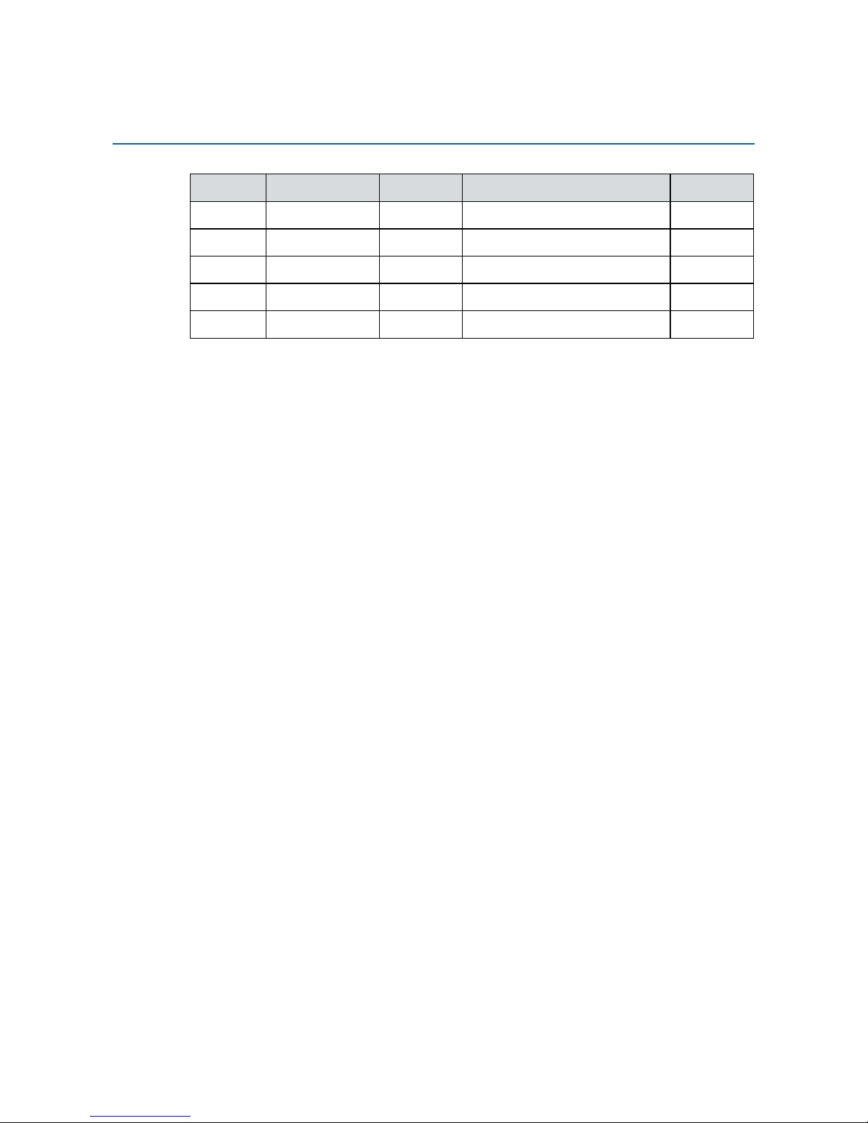
Version Date Page Description Remark
0.1 07/13/2016 All Preliminary Release
1.0 07/28/2016 All Ofcial Release
1.1 09/06/2016 All Update
1.2 04/21/2017 18 Update
1.3 05/09/2017 83 Update
Record of Revision

iii
This manual is released by Vecow Co., Ltd. for reference purpose only. All
product offerings and specications are subject to change without prior notice.
It does not represent commitment of Vecow Co., Ltd. Vecow shall not be liable
for direct, indirect, special, incidental, or consequential damages arising out of
the use of the product or documentation or any infringements upon the rights of
third parties, which may result from such use.
This equipment has been tested and found to comply with the limits for a Class
A digital device, pursuant to part 15 of the FCC Rules. These limits are designed
to provide reasonable protection against harmful interference when the
equipment is operated in a commercial environment. This equipment generates,
uses, and can radiate radio frequency energy, and if it is not installed and used
in accordance with the instruction manual, it may cause harmful interference to
radio communications. Operation of this equipment in a residential area is likely
to cause harmful interference in which case the user will be required to correct
the interference at his own expense.
FCC
The products described in this manual complies with all applicable European
Union (CE) directives if it has a CE marking. For computer systems to
remain CE compliant, only CE-compliant parts may be used. Maintaining CE
compliance also requires proper cable and cabling techniques.
CE
This document contains proprietary information protected by copyright. No part
of this publication may be reproduced in any form or by any means, electric,
photocopying, recording or otherwise, without prior written authorization
by Vecow Co., Ltd. The rights of all the brand names, product names, and
trademarks belong to their respective owners.
Disclaimer
Declaration of Conformity
Copyright and Trademarks
iv
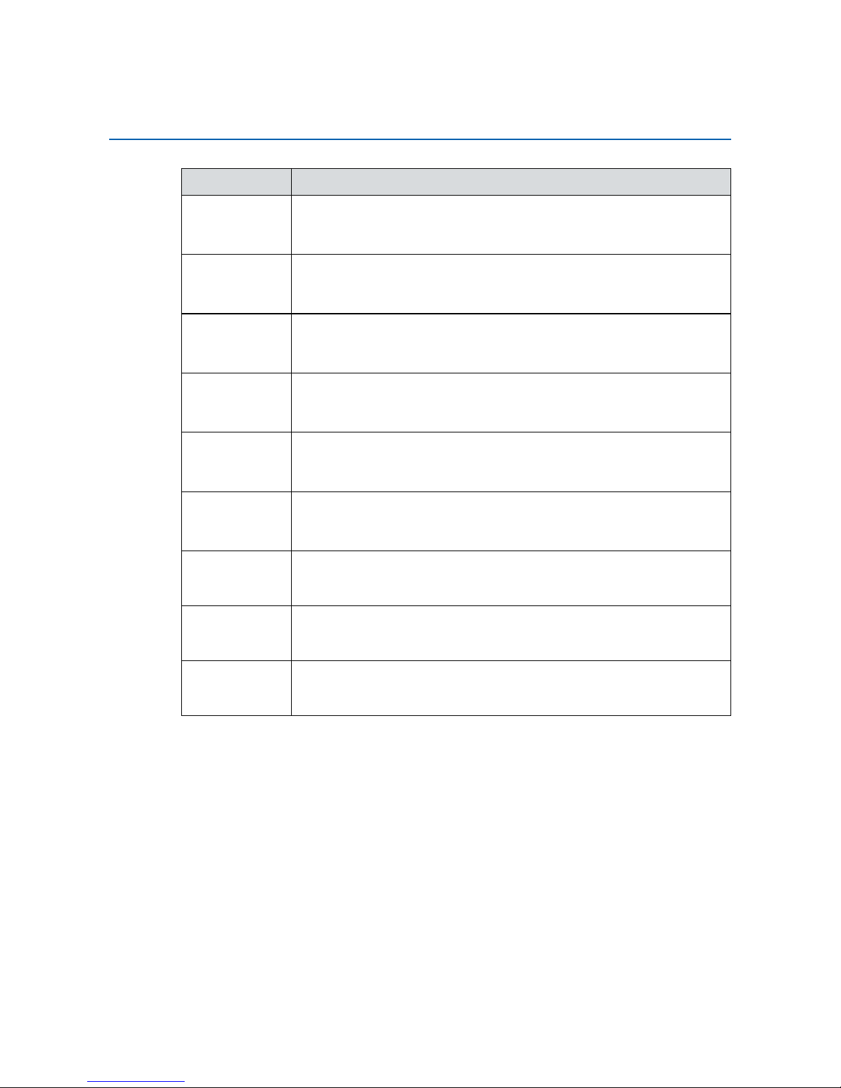
Part Number Description
IVH-9016PoER505M
IVH-9000, Quad Core Intel® Xeon® E3-1505M v5, 18 GbE LAN w/
16 PoE+, 4 SSD Tray, 4 COM, 4 USB 3.0, 4 SIM, Isolated DIO, 16
GPIO
IVH-9016PoER820Q
IVH-9000, Quad Core Intel
®
Core™ i7-6820EQ, 18 GbE LAN w/
16 PoE
+
, 4 SSD Tray, 4 COM, 4 USB 3.0, 4 SIM, Isolated DIO, 16
GPIO
IVH-9016PoER440Q
IVH-9000, Quad Core Intel
®
Core™ i5-6440EQ, 18 GbE LAN w/
16 PoE+, 4 SSD Tray, 4 COM, 4 USB 3.0, 4 SIM, Isolated DIO, 16
GPIO
IVH-9008PoER505M
IVH-9000, Quad Core Intel
®
Xeon® E3-1505M v5, 10 GbE LAN w/
8 PoE+, 4 SSD Tray, 4 COM, 4 USB 3.0, 4 SIM, Isolated DIO, 16
GPIO
IVH-9008PoER820Q
IVH-9000, Quad Core Intel
®
Core™ i7-6820EQ, 10 GbE LAN w/
8 PoE+, 4 SSD Tray, 4 COM, 4 USB 3.0, 4 SIM, Isolated DIO, 16
GPIO
IVH-9008PoER440Q
IVH-9000, Quad Core Intel
®
Core™ i5-6440EQ, 10 GbE LAN w/
8 PoE+, 4 SSD Tray, 4 COM, 4 USB 3.0, 4 SIM, Isolated DIO, 16
GPIO
IVH-90002R505M
IVH-9000, Quad Core Intel
®
Xeon® E3-1505M v5, 2 GbE LAN, 4
SSD Tray, 4 COM, 4 USB 3.0, 4 SIM, Isolated DIO, 16 GPIO
IVH-90002R820Q
IVH-9000, Quad Core Intel
®
Core™ i7-6820EQ, 2 GbE LAN, 4 SSD
Tray, 4 COM, 4 USB 3.0, 4 SIM, Isolated DIO, 16 GPIO
IVH-90002R440Q
IVH-9000, Quad Core Intel
®
Core™ i5-6440EQ, 2 GbE LAN, 4 SSD
Tray, 4 COM, 4 USB 3.0, 4 SIM, Isolated DIO, 16 GPIO
Order Information

v
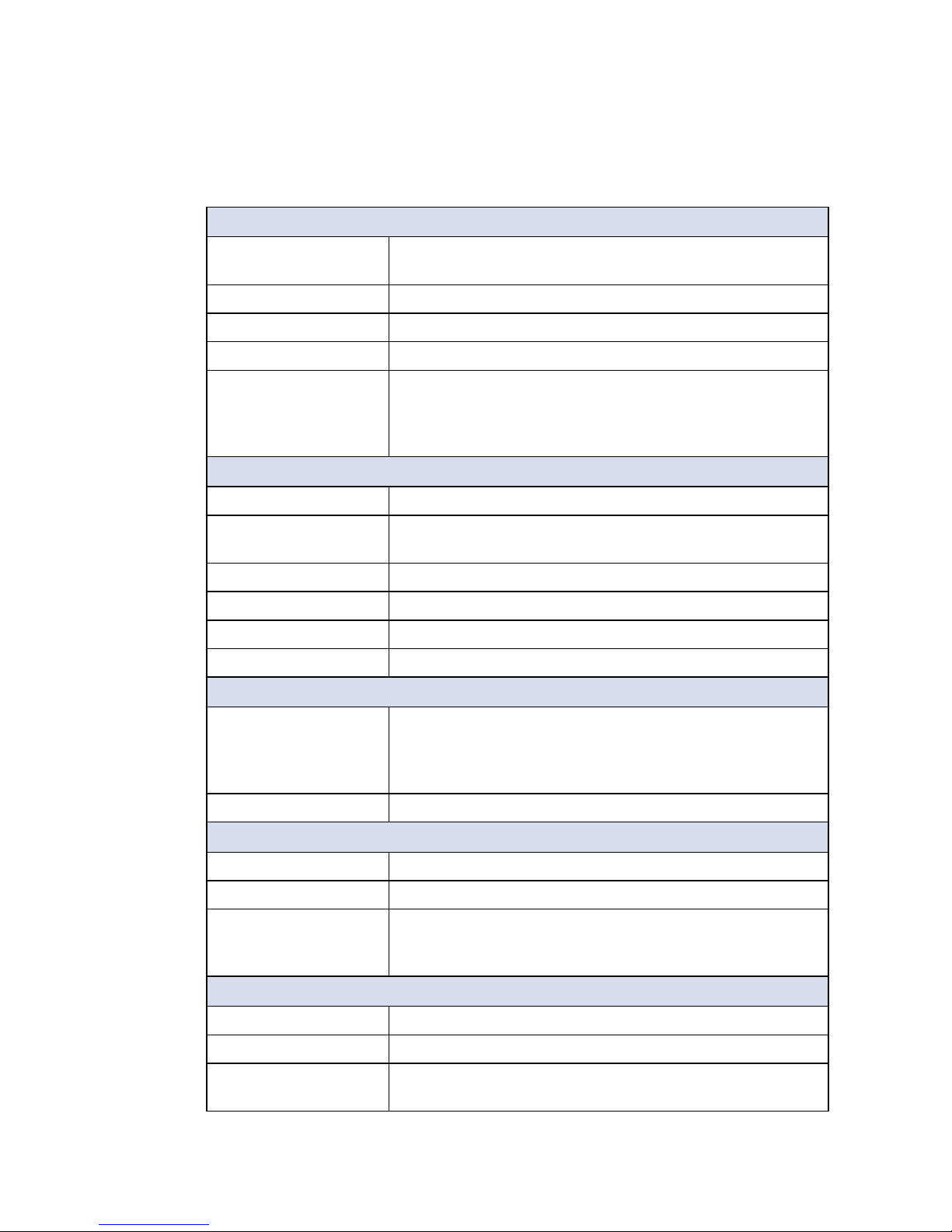
Part Number Description
DDR4 16G
Certied DDR4 16GB 2133MHz RAM
DDR4 8G
Certied DDR4 8GB 2133MHz RAM
DDR4 4G
Certied DDR4 4GB 2133MHz RAM
PWA-280WB-WT 280W, 24V, 85V AC to 264V AC Power Adaptor with 3-pin
Terminal Block (7.62mm pitch), Wide Temperature -30°C to
+70°C
PWA-160WB-WT 160W, 24V, 85V AC to 264V AC Power Adaptor with 3-pin
Terminal Block (7.62mm pitch), Wide Temperature -30°C to
+70°C
VESA Mount
VESA Mounting Kit
DIN-RAIL
DIN Rail Kit
Rack Mount
2U Rackmount Kit
TMBK-20P-100
Terminal Block 20-pin to SCSI Cable, 100cm
TMBK-20P-500
Terminal Block 20-pin to SCSI Cable, 500cm
TMB-SCSI-20P Terminal Board with One 20-pin SCSI Connector and DIN-
Rail Mounting
3G Module
Mini PCIe 3G/GPS Module with Antenna
4G Module
Mini PCIe 4G/GPS Module with Antenna
WiFi & Bluetooth
Module
Intel
®
Mini PCIe WiFi & Bluetooth Module with Antenna
Order Accessories

vi
Table of Contents
CHAPTER 1 GENERAL INTRODUCTION 1
1.1 Overview 1
1.2 Features 1
1.3 Product Specication 2
1.3.1 Specications of IVH-9016-PoER 2
1.3.2 Specications of IVH-9008-PoER 4
1.3.3 Specications of IVH-9000-2R 6
1.4 Supported CPU List 8
1.5 Mechanical Dimension 9
1.5.1 Dimensions of IVH-9016-PoER 9
1.5.2 Dimensions of IVH-9008-PoER 9
1.5.3 Dimensions of IVH-9000-2R 9
CHAPTER 2 GETTING TO KNOW YOUR IVH-9000 10
2.1 Packing List 10
2.2 Front Panel I/O Functions 11
2.3 Rear Panel I/O and Functions 19
2.4 Main Board Expansion Connectors 25
2.5 Main Board Jumper & Deep Switch Settings 44
2.6 Ignition Control 50
CHAPTER 3 SYSTEM SETUP 53
3.1 How to Open Your IVH-9000 53
3.2 Installing DDR4 SO-DIMM Modules 55
3.3 Installing Mini PCIe Card 56
3.4 Installing Antenna Cable 57

vii
3.5 Installing CFast Card and SIM Card 59
3.6 Installing SSD/HDD 61
3.7 Mounting Your IVH-9000 63
CHAPTER 4 BIOS AND DRIVER SETTING 69
4.1 Entering Setup 69
4.2 Main Menu 70
4.3 Advanced Functions 71
4.4 Chipset Functions 81
4.5 Security Functions 86
4.6 Boot Functions 87
4.7 Save & Exit 88
APPENDIX A : ISOLATED DIO GUIDE 89
APPENDIX B : GPIO & WDT Functions 94
APPENDIX C : RAID Installation Guide 95
APPENDIX D : Power Consumption 99

1
GENERAL INTRODUCTION
1
GENERAL INTRODUCTION
Powered by server-grade Quad Core Intel® Xeon®/ Core™ i7 processor
(Skylake-H), ECC/ non-ECC DDR4 dual channel up to 32GB memory; Intel®
HD P530/ 530 graphics supports DVI-D and dual DisplayPort interface, up to
4K display, fanless -25°C to 70°C operating temperature, all-in-one integrated
features, multiple I/O connection, user-friendly, smart manageability, excellent
mobile availability, 6V to 78V power input with 200V surge protection,
configurable ignition power control, intelligent circus protection and rugged
reliability in harsh environments, Vecow IVH-9000 Series Fanless Vehicle
Computing System is your perfect choices for Rolling Stock System, Machine
Vision, Intelligent Transportation System (ITS), Mobile DVR/NVR, Intelligent
Surveillance, Fleet Management, Industry 4.0, Internet of Things (IoT) and any
performance driven real-time vehicle computing applications.
1.1 Overview
1.2 Features
• Quad Core Intel® Xeon®/ Core™ i7/ i5/ i3 Processor (Skylake-H) with CM236
Chipset supports up to 4K display
• 2 DDR4 2133MHz Memory, up to 32GB (ECC/ Non-ECC)
• Fanless, -25°C to 70°C Operating Temperature
• 18 Gigabit LAN with 16 IEEE 802.3at PoE
+
compliant, iAMT 11.0 supported
• 4 Mini PCIe Slot
• 4 SIM Card Socket (3 External)
• 4 Front-access 2.5" HDD/ SSD Tray, 5 USB
• Supports 3G/ 4G/ LTE/ WiFi/ GPRS/ UMTS
• 16 Isolated DIO, 16 GPIO
• Configurable Ignition Power Control
• 6V to 78V DC Power Input with 200V Surge Protection
• UPS supported (Optional)
2
GENERAL INTRODUCTION
©Vecow IVH-9000 User Manual
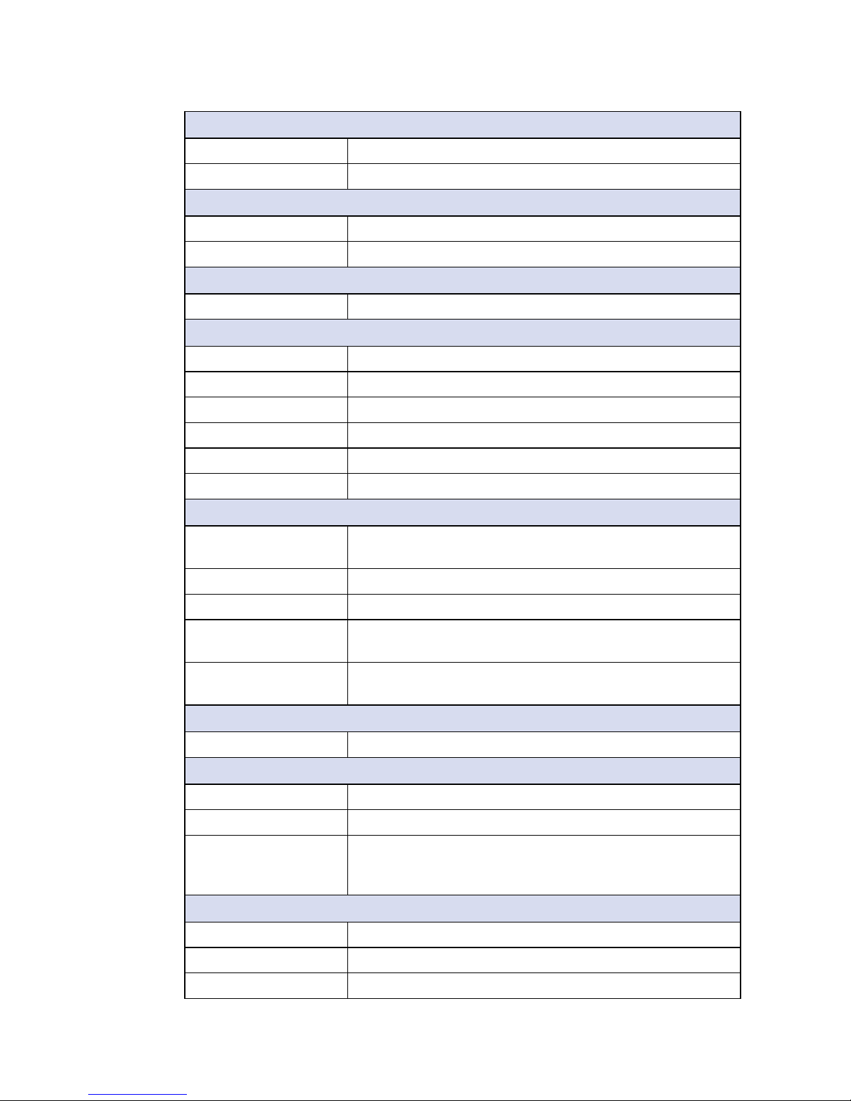
1.3 Product Specication
1.3.1 Specications of IVH-9016-PoER
System
Processor Quad Core Intel® Xeon® E3-1505M v5/ Core™ i7-6820EQ/
i5-6440EQ Processor (Skylake-H)
Chipset Intel
®
CM236
BIOS AMI
SIO IT8786E
Memory • DDR4 2133MHz
• Up to 32GB
• 2 260-pin SO-DIMM Socket
(ECC Function enable depends on processor support)
I/O Interface
Serial 4 COM RS-232/ 422/ 485 w/ auto flow control
USB • 4 USB 3.0 (Front)
• 1 USB 2.0 (Internal)
Isolated DIO 16 Isolated DIO (8 DI, 8 DO)
GPIO 16 GPIO
LED Power, HDD, Wireless, PoE
SIM Card 4 SIM Card Socket (3 External, 1 Internal)
Expansion
Mini PCIe 4 Mini PCIe Socket :
• 1 Mini PCIe Socket for PCIe/ USB/ Internal SIM Card/
Optional mSATA
• 3 Mini PCIe Socket for PCIe/ USB/ External SIM Card
SUMIT A, B 2 SUMIT Slot (Optional)
Graphics
Graphics Processor Intel® HD Graphics P530/ 530
Display Memory Shared Memory, up to 1.7GB
Interface • DVI-D : Up to 1920 x 1200 @ 60Hz
• DisplayPort 1 : Up to 4096 x 2304 @ 60Hz
• DisplayPort 2 : Up to 4096 x 2304 @ 60Hz
Storage
SATA 6 SATA III (6Gbps) support software RAID 0, 1, 5, 10
mSATA 1 SATA III (Mini PCIe Type, 6Gbps)
Storage Device • 1 CFast Socket, Push-in/ Push-out Ejector
• 4 Front-access 2.5" SSD/ HDD Tray
3
GENERAL INTRODUCTION
Audio
Audio Codec Realtek ALC892, 5.1 Channel HD Audio
Audio Interface 1 Mic-in, 1 Line-out
Ethernet
LAN 1 Intel® I219 Gigabit LAN supports iAMT 11.0
LAN 2 Intel
®
I210 Gigabit LAN
PoE
LAN 3 to LAN 18 Gigabit IEEE 802.3at (25.5W/48V) PoE+ by Intel® I350
Power
Power Input 6V to 78V, DC-in
Power Interface 3-pin Terminal Block : V+, V-, Frame Ground
Ignition Control 16 Mode (Internal)
Remote Switch 5-pin Terminal Block : On, Off, IGN, LED+, LED-
Surge Protection Up to 200V/1ms Transient Power
UPS Supported (Optional)
Others
TPM Optional Inneon SLB9665 supports TPM 2.0, LPC
interface
Watchdog Timer Reset : 1 to 255 sec./min. per step
Smart Management Wake on LAN, PXE supported
HW Monitor Monitoring temperature, voltages. Auto throttling control
when CPU overheats.
GPS Onboard GPS Module supports Accelerometer, Gyroscope
and Odometer (Optional)
Software Support
OS Windows 10, Windows 8.1, Windows 7, Linux
Mechanical
Dimensions (WxLxH) 260mm x 215mm x 79mm (10.2" x 8.5" x 3.1")
Weight 4.2 kg (9.26 lb)
Mounting • Wallmount by mounting bracket
• DIN Rail Mount (Optional)
• 2U Rackmount (Optional)
Environment
Operating Temperature -25°C to 70°C (-13°F to 158°F)
Storage Temperature -40°C to 85°C (-40°F to 185°F)
Humidity 5% to 95% Humidity, non-condensing
4
GENERAL INTRODUCTION
©Vecow IVH-9000 User Manual
Relative Humidity 95% at 70°C
Shock • IEC 60068-2-27
• SSD : 50G @ Wallmount, Half-sine, 11ms
Vibration • IEC 60068-2-64
• SSD : 5Grms, 5Hz to 500Hz, 3 Axis
EMC CE, FCC, EN 50155, EN 50121-3-2
1.3.2 Specications of IVH-9008-PoER
System
Processor Quad Core Intel® Xeon® E3-1505M v5/ Core™ i7-6820EQ/
i5-6440EQ Processor (Skylake-H)
Chipset Intel
®
CM236
BIOS AMI
SIO IT8786E
Memory • DDR4 2133MHz
• Up to 32GB
• 2 260-pin SO-DIMM Socket
(ECC Function enable depends on processor support)
I/O Interface
Serial 4 COM RS-232/ 422/ 485 w/ auto flow control
USB • 4 USB 3.0 (Front)
• 1 USB 2.0 (Internal)
Isolated DIO 16 Isolated DIO (8 DI, 8 DO)
GPIO 16 GPIO
LED Power, HDD, Wireless, PoE
SIM Card 4 SIM Card Socket (3 External, 1 Internal)
Expansion
Mini PCIe 4 Mini PCIe Socket :
• 1 Mini PCIe Socket for PCIe/ USB/ Internal SIM Card/
Optional mSATA
• 3 Mini PCIe Socket for PCIe/ USB/ External SIM Card
SUMIT A, B 2 SUMIT Slot (Optional)
Graphics
Graphics Processor Intel® HD Graphics P530/ 530
Display Memory Shared Memory, up to 1.7GB
Interface • DVI-D : Up to 1920 x 1200 @ 60Hz
• DisplayPort 1 : Up to 4096 x 2304 @ 60Hz
• DisplayPort 2 : Up to 4096 x 2304 @ 60Hz
5
GENERAL INTRODUCTION
Storage
SATA 6 SATA III (6Gbps) support software RAID 0, 1, 5, 10
mSATA 1 SATA III (Mini PCIe Type, 6Gbps)
Storage Device • 1 CFast Socket, Push-in/ Push-out Ejector
• 4 Front-access 2.5" SSD/ HDD Tray
Audio
Audio Codec Realtek ALC892, 5.1 Channel HD Audio
Audio Interface 1 Mic-in, 1 Line-out
Ethernet
LAN 1 Intel® I219 Gigabit LAN supports iAMT 11.0
LAN 2 Intel
®
I210 Gigabit LAN
PoE
LAN 3 to LAN 10 Gigabit IEEE 802.3at (25.5W/48V) PoE+ by Intel® I350
Power
Power Input 6V to 78V, DC-in
Power Interface 3-pin Terminal Block : V+, V-, Frame Ground
Ignition Control 16 Mode (Internal)
Remote Switch 5-pin Terminal Block : On, Off, IGN, LED+, LED-
Surge Protection Up to 200V/1ms Transient Power
UPS Supported (Optional)
Others
TPM Optional Inneon SLB9665 supports TPM 2.0, LPC
interface
Watchdog Timer Reset : 1 to 255 sec./min. per step
Smart Management Wake on LAN, PXE supported
HW Monitor Monitoring temperature, voltages. Auto throttling control
when CPU overheats.
GPS Onboard GPS Module supports Accelerometer, Gyroscope
and Odometer (Optional)
Software Support
OS Windows 10, Windows 8.1, Windows 7, Linux
Mechanical
Dimensions (WxLxH) 260mm x 215mm x 79mm (10.2" x 8.5" x 3.1")
Weight 4.2 kg (9.26 lb)
Mounting • Wallmount by mounting bracket
• DIN Rail Mount (Optional)
• 2U Rackmount (Optional)
6
GENERAL INTRODUCTION
©Vecow IVH-9000 User Manual
Environment
Operating Temperature -25°C to 70°C (-13°F to 158°F)
Storage Temperature -40°C to 85°C (-40°F to 185°F)
Humidity 5% to 95% Humidity, non-condensing
Relative Humidity 95% at 70°C
Shock • IEC 60068-2-27
• SSD : 50G @ Wallmount, Half-sine, 11ms
Vibration • IEC 60068-2-64
• SSD : 5Grms, 5Hz to 500Hz, 3 Axis
EMC CE, FCC, EN 50155, EN 50121-3-2
1.3.3 Specications of IVH-9000-2R
System
Processor Quad Core Intel® Xeon® E3-1505M v5/ Core™ i7-6820EQ/
i5-6440EQ Processor (Skylake-H)
Chipset Intel
®
CM236
BIOS AMI
SIO IT8786E
Memory • DDR4 2133MHz
• Up to 32GB
• 2 260-pin SO-DIMM Socket
(ECC Function enable depends on processor support)
I/O Interface
Serial 4 COM RS-232/ 422/ 485 w/ auto flow control
USB • 4 USB 3.0 (Front)
• 1 USB 2.0 (Internal)
Isolated DIO 16 Isolated DIO (8 DI, 8 DO)
GPIO 16 GPIO
LED Power, HDD, Wireless
SIM Card 4 SIM Card Socket (3 External, 1 Internal)
Expansion
Mini PCIe 4 Mini PCIe Socket :
• 1 Mini PCIe Socket for PCIe/ USB/ Internal SIM Card/
Optional mSATA
• 3 Mini PCIe Socket for PCIe/ USB/ External SIM Card
SUMIT A, B 2 SUMIT Slot (Optional)
7
GENERAL INTRODUCTION
Graphics
Graphics Processor Intel® HD Graphics P530/ 530
Display Memory Shared Memory, up to 1.7GB
Interface • DVI-D : Up to 1920 x 1200 @ 60Hz
• DisplayPort 1 : Up to 4096 x 2304 @ 60Hz
• DisplayPort 2 : Up to 4096 x 2304 @ 60Hz
Storage
SATA 6 SATA III (6Gbps) support software RAID 0, 1, 5, 10
mSATA 1 SATA III (Mini PCIe Type, 6Gbps)
Storage Device • 1 CFast Socket, Push-in/ Push-out Ejector
• 4 Front-access 2.5" SSD/ HDD Tray
Audio
Audio Codec Realtek ALC892, 5.1 Channel HD Audio
Audio Interface 1 Mic-in, 1 Line-out
Ethernet
LAN 1 Intel® I219 Gigabit LAN supports iAMT 11.0
LAN 2 Intel
®
I210 Gigabit LAN
Power
Power Input 6V to 78V, DC-in
Power Interface 3-pin Terminal Block : V+, V-, Frame Ground
Ignition Control 16 Mode (Internal)
Remote Switch 5-pin Terminal Block : On, Off, IGN, LED+, LED-
Surge Protection Up to 200V/1ms Transient Power
UPS Supported (Optional)
Others
TPM Optional Inneon SLB9665 supports TPM 2.0, LPC
interface
Watchdog Timer Reset : 1 to 255 sec./min. per step
Smart Management Wake on LAN, PXE supported
HW Monitor Monitoring temperature, voltages. Auto throttling control
when CPU overheats.
GPS Onboard GPS Module supports Accelerometer, Gyroscope
and Odometer (Optional)
Software Support
OS Windows 10, Windows 8.1, Windows 7, Linux
Mechanical
Dimensions (WxLxH) 260mm x 215mm x 79mm (10.2" x 8.5" x 3.1")
8
GENERAL INTRODUCTION
©Vecow IVH-9000 User Manual
1.4 Supported CPU List
Processor No. TDP Cache Max. Frequency Embedded
Xeon
®
E3-1575M v5 45W 8M Up to 3.00 GHz
Xeon
®
E3-1545M v5 45W 8M Up to 2.90 GHz
Xeon
®
E3-1535M v5 45W 8M Up to 2.80 GHz
Xeon
®
E3-1515M v5 45W 8M Up to 2.80 GHz
Xeon
®
E3-1505M v5 45W 8M Up to 2.80 GHz Ye s
Xeon
®
E3-1505L v5 25W 8M Up to 2.00 GHz
Core i7-6970HQ 45W 8M Up to 3.70 GHz
Core i7-6920HQ 45W 8M Up to 3.80 GHz
Core i7-6870HQ 45W 8M Up to 3.60 GHz
Core i7-6820HQ 45W 8M Up to 3.60 GHz
Core i7-6770HQ 45W 6M Up to 3.50 GHz
Core i7-6700HQ 45W 6M Up to 3.50 GHz
Core i7-6820EQ 45W 8M Up to 3.50 GHz Ye s
Core i7-6822EQ 25W 8M Up to 2.80 GHz
Core i5-6440HQ 45W 6M Up to 3.50 GHz
Core i5-6350HQ 45W 6M Up to 3.20 GHz
Core i5-6300HQ 45W 6M Up to 3.20 GHz
Core i5-6440EQ 45W 6M Up to 3.40 GHz Ye s
Core i5-6442EQ 45W 6M Up to 2.70 GHz
Weight 4.2 kg (9.26 lb)
Mounting • Wallmount by mounting bracket
• DIN Rail Mount (Optional)
• 2U Rackmount (Optional)
Environment
Operating Temperature -25°C to 70°C (-13°F to 158°F)
Storage Temperature -40°C to 85°C (-40°F to 185°F)
Humidity 5% to 95% Humidity, non-condensing
Relative Humidity 95% at 70°C
Shock • IEC 60068-2-27
• SSD : 50G @ Wallmount, Half-sine, 11ms
Vibration • IEC 60068-2-64
• SSD : 5Grms, 5Hz to 500Hz, 3 Axis
EMC CE, FCC, EN 50155, EN 50121-3-2
9
GENERAL INTRODUCTION
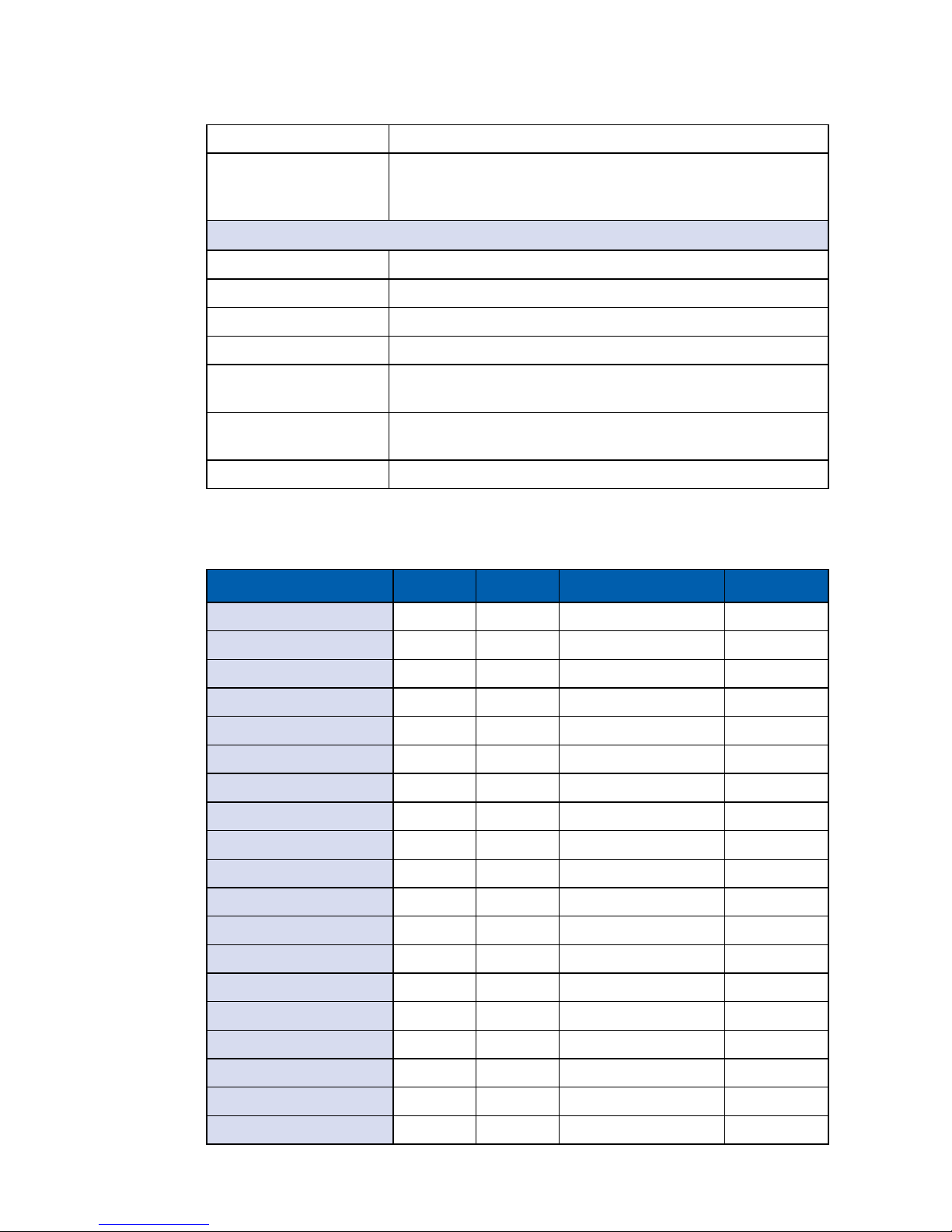
1.5 Mechanical Dimension
1.5.1 Dimensions of IVH-9016-PoER
297 (11.7)
282 (11.1)
297 (11.7)
260 (10.2)
155 (6.1)
215 (8.6)
791 (3.1)
Unit: mm (inch)
1.5.2 Dimensions of IVH-9008-PoER
297 (11.7)
282 (11.1)
297 (11.7)
260 (10.2)
155 (6.1)
215 (8.6)
791 (3.1)
Unit: mm (inch)
1.5.3 Dimensions of IVH-9000-2R
297 (11.7)
282 (11.1)
297 (11.7)
260 (10.2)
155 (6.1)
215 (8.6)
791 (3.1)
Unit: mm (inch)

10
GETTING TO KNOW YOUR IVH-9000©Vecow IVH-9000 User Manual
2
GETTING TO KNOW YOUR IVH-9000
2.1 Packing List
Item Description Qty
1 IVH-9000 In-Vehicle Fanless Embedded System (According
to the conguration you order, the IVH-9000 series may
contain SSD/HDD and DDR4 SO-DIMM. Please verify these
items if necessary.)
1
2 Accessory box, which contains
● Vecow Drivers & Utilities DVD
● Wall-mounting bracket
● KHS#6-32x6 screw for wall-mounting bracket
● M2.5x6 screw for Mini PCIe socket
● 3-pin pluggable terminal block
● 5-pin Pluggable terminal block
● 20-pin pluggable terminal block
● Foot Pad
● HDD Tray Key
1
2
4
8
1
1
1
4
2
11
GETTING TO KNOW YOUR IVH-9000
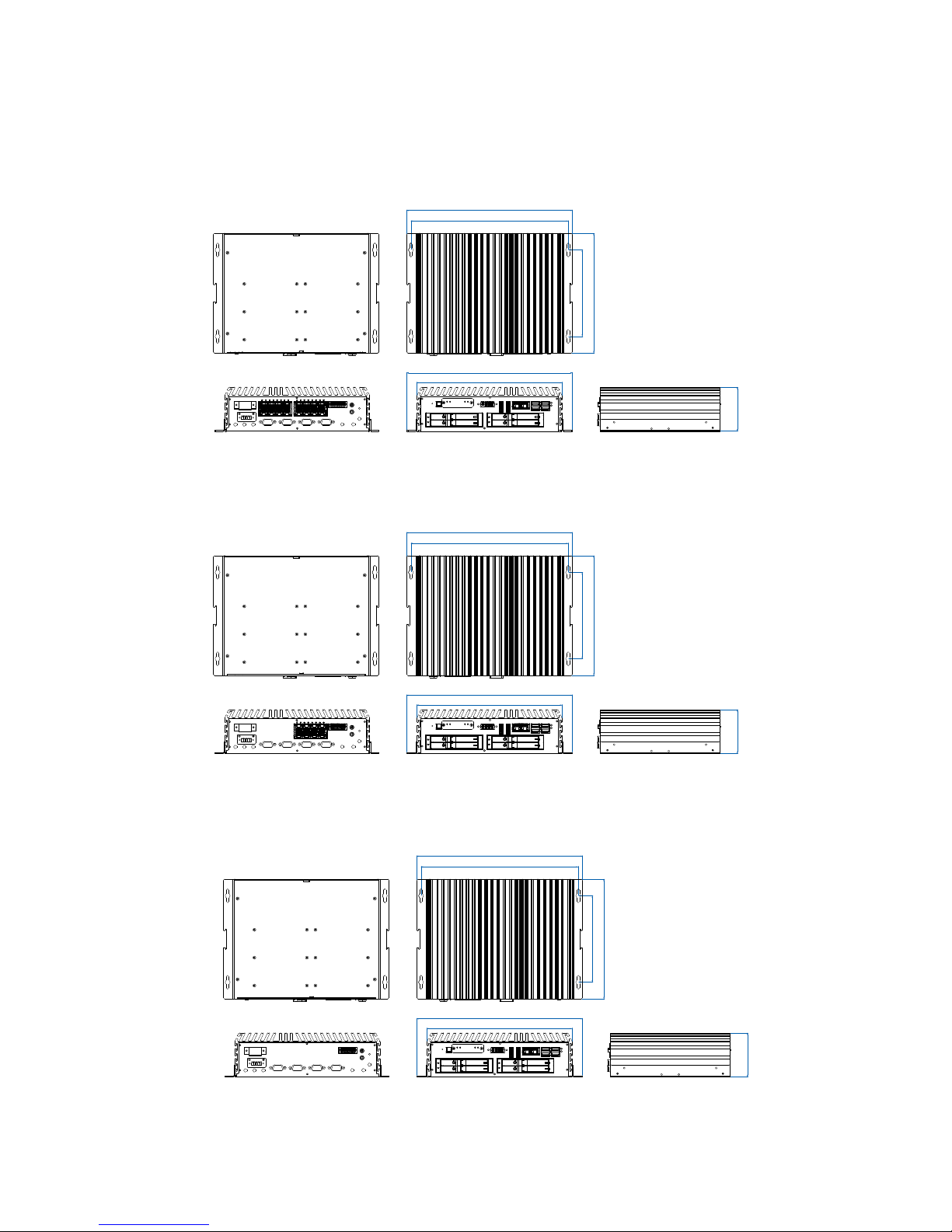
2.2 Front Panel I/O Functions
In Vecow IVH-9000 series family, all I/O connectors are located on front panel
and rear panel. Most of the general connections to computer device, such as
USB, LAN Jack, Display, DVI-D, Display Port and any additional storage, are
placed on the front panel.
CFast
SIM 3 SIM 4
SIM 2
1 2 3 4
WLAN
RESET
POWER
DVI-D DP 1 DP 2 USB 3.0 USB 3.0
HDD
PWR
LAN 1 LAN 2
2.2.1 Reset Tact Switch
It is a hardware reset switch. Use this switch to reset the system without power
off the system. Press the Reset Switch for a few seconds, then reset will be
enabled.
CFast
SIM 3 SIM 4
SIM 2
1 2 3 4
WLAN
RESET
POWER
DVI-D DP 1 DP 2 USB 3.0 USB 3.0
HDD
PWR
LAN 1 LAN 2

12
GETTING TO KNOW YOUR IVH-9000©Vecow IVH-9000 User Manual
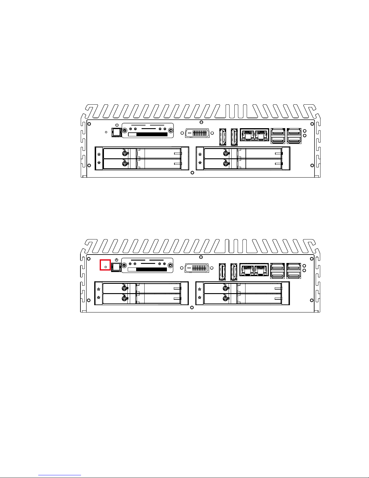
2.2.2 Power Button
The Power Button is a non-latched switch with dual color LED indication. It
indicates power status: S0, S3 and S5. More detail LED indications are listed as
follows:
To power on the system, press the power button and then the blue LED is
lightened.
To power off the system, you can either command shutdown by OS operation,
or just simply press the power button.
If system error, you can just press the power button for 4 seconds to shut down
the machine directly.
Please do note that a 4-second interval between each 2 power-on/ power-off
operation is necessary in normal working status. (For example, once turning
off the system, you have to wait for 4 seconds to initiate another power-on
operation).
LED Color Power Status System Status
Solid Blue S0 System working
Solid Orange S3, S5 Suspend to RAM, System off with standby power
CFast
SIM 3 SIM 4
SIM 2
1 2 3 4
WLAN
RESET
POWER
DVI-D DP 1 DP 2 USB 3.0 USB 3.0
HDD
PWR
LAN 1 LAN 2
13
GETTING TO KNOW YOUR IVH-9000
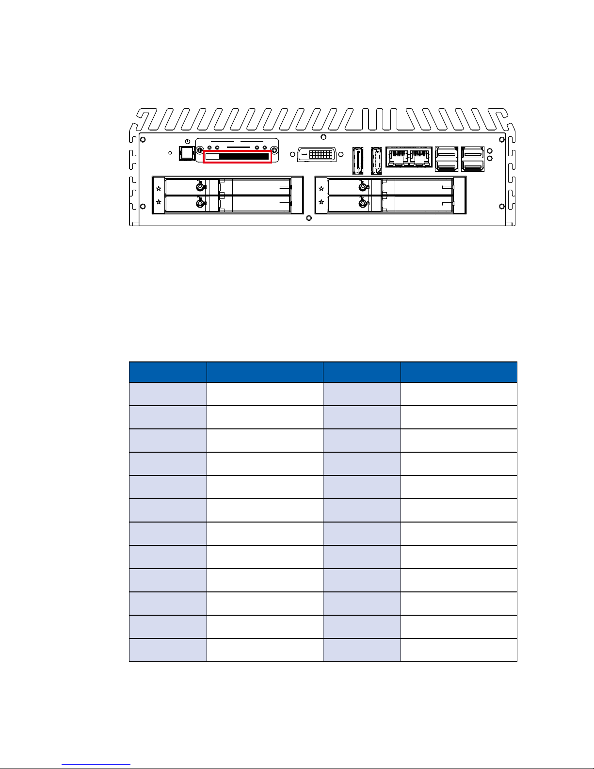
2.2.3 CFast Card
There is a CFast socket on the front panel supporting Type-I/II Compact Flash
card.
It is implemented by a SATA III Port from CM236 PCH. Be sure to disconnect
the power source and unscrew the CFast socket cover before installing a CFast
card. The IVH-9000 does not support the CFast hot swap and PnP (Plug and
Play) functions. It is necessary to remove power source rst before inserting or
removing the CFast card.
The pinouts of CFast port are listed as follows:
Pin No. Description Pin No. Description
S1 GND PC6 NC
S2 SATA_TXP5
PC7 GND
S3 SATA_TXN5
PC8 CFAST_LED
S4 GND
PC9 NC
S5 SATA_RXN5
PC10 NC
S6 SATA_RXP5
PC11 NC
S7 GND
PC12 NC
PC1 GND
PC13 +3.3V
PC2 GND
PC14 +3.3V
PC3 NC
PC15 GND
PC4 NC
PC16 GND
PC5 NC
PC17 NC
CFast
SIM 3 SIM 4
SIM 2
1 2 3 4
WLAN
RESET
POWER
DVI-D DP 1 DP 2 USB 3.0 USB 3.0
HDD
PWR
LAN 1 LAN 2
14
GETTING TO KNOW YOUR IVH-9000©Vecow IVH-9000 User Manual
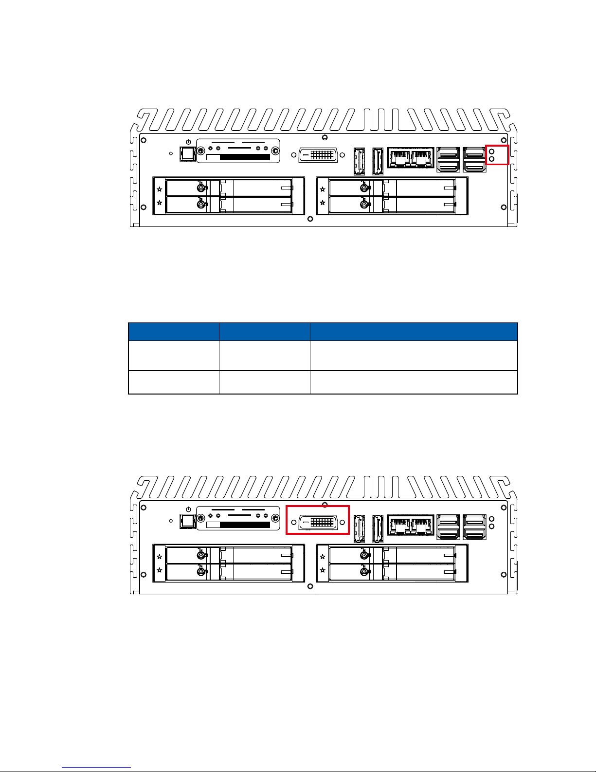
2.2.5 DVI-D Connector
The DVI-D connector on the front panel supports both DVI display. This
connector can either output DVI signals signal. The DVI output mode supports
up to 1920 x 1200 resolution and output mode supports up to 1920 x 1200
resolution. The DVI is automatically selected according to the display device
connected. You will need a DVI-D cable when connecting to a display device.
2.2.4 PWR and HDD LED Indicator
HDD LED/ Yellow: A Hard Disk/ CFast LED. If the LED is on, it indicates that the
system’s storage is functional. If it is off, it indicates that the system’s storage is
not functional. If it is ashing, it indicates data access activities.
Power LED/ Green: If the LED is solid green, it indicates that the system is
powered on.
LED Color Power Status System Status
Yellow HDD/ CFast
• On/ Off : Storage status, function or not.
• Twinkling : Data transferring.
Green Power System power status (on/ off)
CFast
SIM 3 SIM 4
SIM 2
1 2 3 4
WLAN
RESET
POWER
DVI-D DP 1 DP 2 USB 3.0 USB 3.0
HDD
PWR
LAN 1 LAN 2
CFast
SIM 3 SIM 4
SIM 2
1 2 3 4
WLAN
RESET
POWER
DVI-D DP 1 DP 2 USB 3.0 USB 3.0
HDD
PWR
LAN 1 LAN 2
15
GETTING TO KNOW YOUR IVH-9000
2.2.6 DisplayPort
Onboard Display Port support auxiliary channel dual mode, connection supports
up to 4096x2304 resolution at 60 Hz.
Multi-Stream Transport Display Resolutions Table:
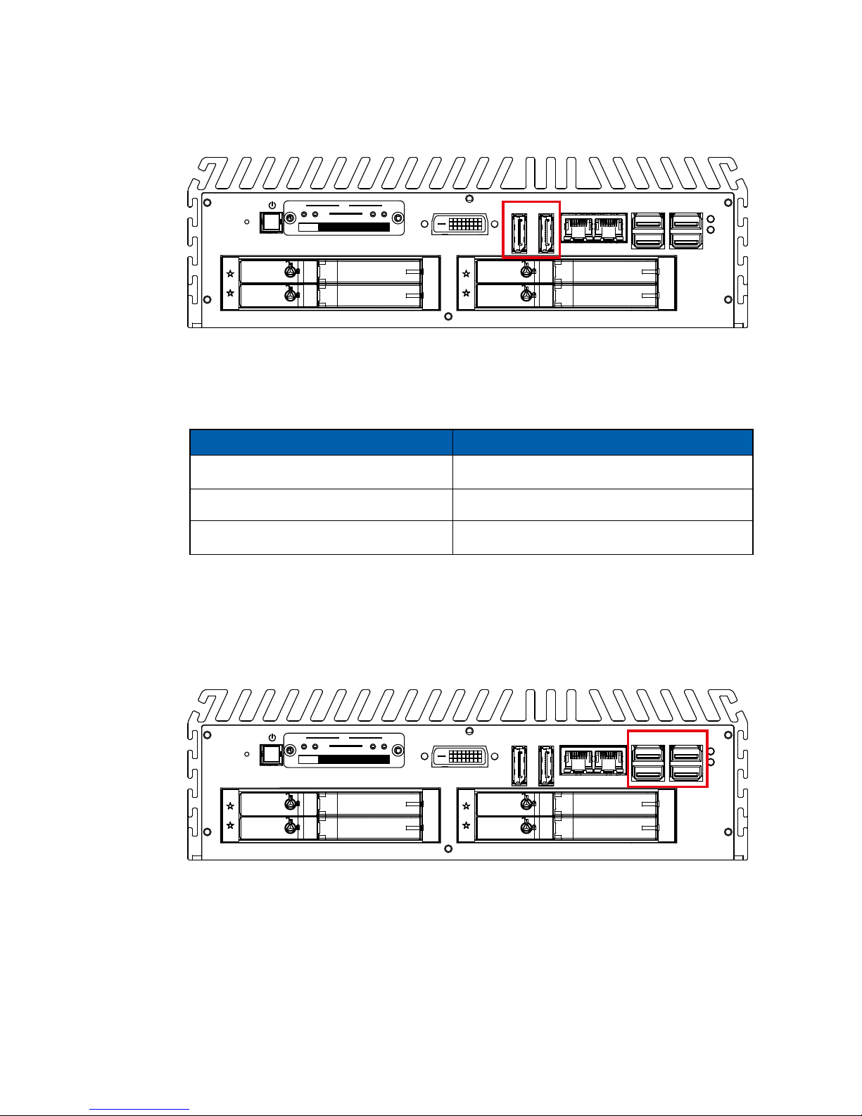
2.2.7 USB 3.0
There are 4 USB 3.0 connections available supporting up to 5GB per second
data rate in the front side of IVH-9000. It also compliant with the requirements of
Super Speed (SS), high speed (HS), full speed (FS) and low speed (LS).
CFast
SIM 3 SIM 4
SIM 2
1 2 3 4
WLAN
RESET
POWER
DVI-D DP 1 DP 2 USB 3.0 USB 3.0
HDD
PWR
LAN 1 LAN 2
CFast
SIM 3 SIM 4
SIM 2
1 2 3 4
WLAN
RESET
POWER
DVI-D DP 1 DP 2 USB 3.0 USB 3.0
HDD
PWR
LAN 1 LAN 2
Multi-Stream Transport Display Max. Resolution
One panel Display 4096x2304@60Hz
Two panel Displays concurrently 2880x1800@60Hz
Three panel Displays concurrently 2304x1440@60Hz
16
GETTING TO KNOW YOUR IVH-9000©Vecow IVH-9000 User Manual
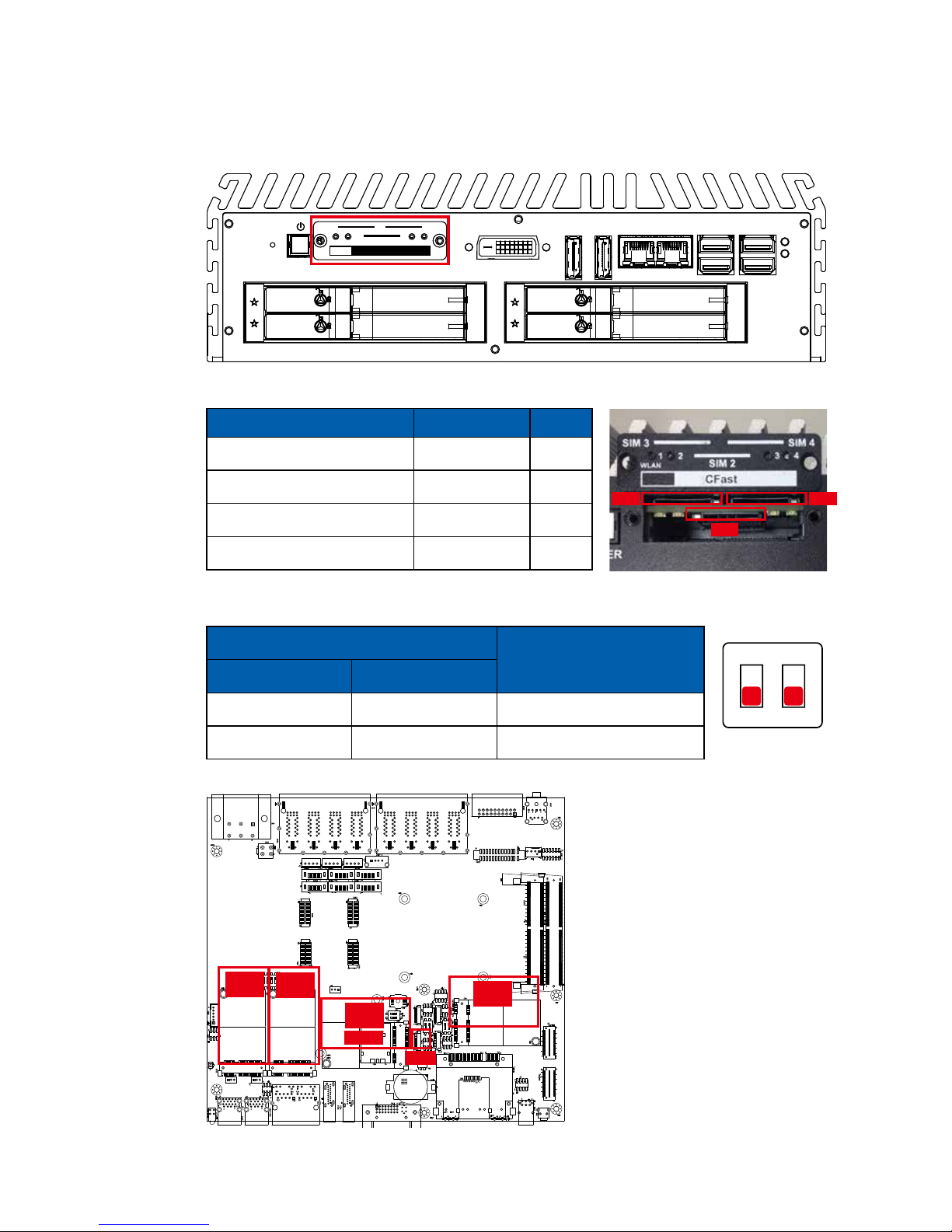
2.2.8 WLAN LED, Mini PCIe, SIM Card Comparison
CFast
SIM 3 SIM 4
SIM 2
1 2 3 4
WLAN
RESET
POWER
DVI-D DP 1 DP 2 USB 3.0 USB 3.0
HDD
PWR
LAN 1 LAN 2
Mini
PCIe 4
Mini
PCIe 1
SW1
Mini
PCIe 2
mSATA
Note:
The SIM card sockets do not
support hot-plug. Please make
sure to unplug the system
power before inserting the SIM
card(s).
Mini
PCIe 3
SW1: Mini PCIe 1/ mSATA Select SW
DIP Switch
LED
SW 1-1 SW 1-2
ON N/C Mini PCIe
OFF N/C Auto Detection (Default)
ON
1 2
Mini PCIe SIM LED
Mini PCIe 1/ mSATA (CN4) SIM 1 (CN5) 1
Mini PCIe 2 (CN6) SIM 2 (CN7) 2
Mini PCIe 3 (CN8) SIM 3 (CN9) 3
Mini PCIe 4 (CN10) SIM 4 (CN42) 4
Mini PCIe Slot/ SIM Slot/ WLAN LED Mapping Table :
SIM 3
SIM 2
SIM 4
17
GETTING TO KNOW YOUR IVH-9000
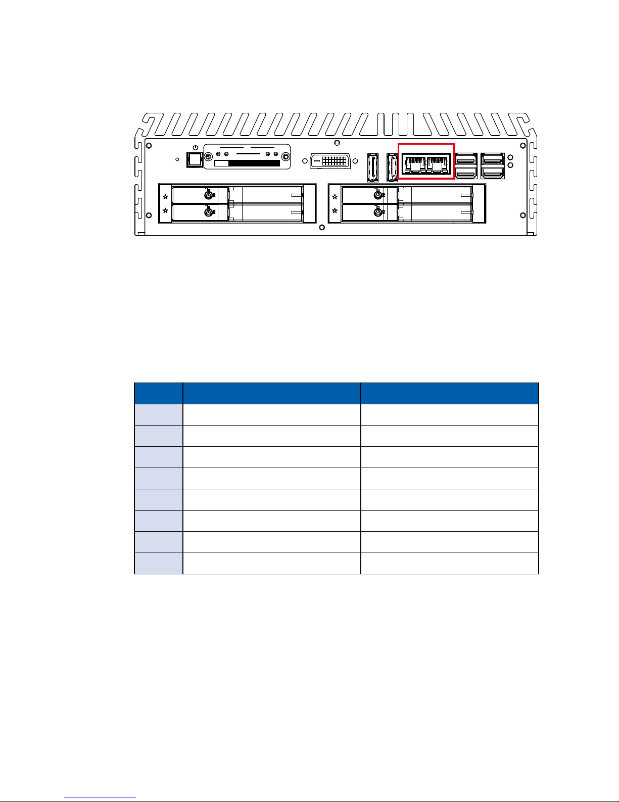
Pin No. 10/ 100Mbps 1000Mbps
1 E_TX+ MDI0_P
2 E_TX- MDI0_N
3 E_RX+ MDI1_P
4 ---- MDI2_P
5 ----- MDI2_N
6 E_RX- MDI1_N
7 ----- MDI3_P
8 ------ MDI3_N
Each LAN port is supported by standard RJ-45 connector with LED indicators to
present Active/ Link/ Speed status of the connection.
The LED indicator on the right bottom corner lightens in solid green when the
cable is properly connected to a 100 Mbps Ethernet network; The LED indicator
on the right bottom corner lightens in solid orange when the cable is properly
connected to a 1000Mbps Ethernet network; The left LED will keep twinkling/ off
when Ethernet data packets are being transmitted/ received.
2.2.9 10/ 100/ 1000 Mbps Ethernet Port
There are 2 8-pin RJ-45 jacks supporting 10/ 100/1000 Mbps Ethernet
connections in the front side. LAN 1 is powered by Intel i219 Ethernet Phy; LAN
2 is powered by Intel I210 Ethernet engine. When both LAN 1 and LAN 2 work
in normal status, iAMT 11.0 function is enabled.
Using suitable RJ-45 cable, you can connect the system to a computer, or to
any other devices with Ethernet connection, for example, a hub or a switch.
Moreover, both of LAN 1 and LAN 2 supports Wake on LAN and Pre-boot
functions. The pin-outs of LAN 1 and LAN 2 are listed as follows:
CFast
SIM 3 SIM 4
SIM 2
1 2 3 4
WLAN
RESET
POWER
DVI-D DP 1 DP 2 USB 3.0 USB 3.0
HDD
PWR
LAN 1 LAN 2

18
GETTING TO KNOW YOUR IVH-9000©Vecow IVH-9000 User Manual
2.2.10 Front-access SSD/ HDD Tray
There are 4 front-access 2.5” SSD/ HDD trays in the front side of IVH-9000. Just
trigger to open the SSD/ HDD tray, up to 8TB is available.
HDD Tray MB Connector
HDD 1 SATA1
HDD 2 S ATA2
HDD 3 S ATA3
HDD 4 S ATA4
CFast
SIM 3 SIM 4
SIM 2
1 2 3 4
WLAN
RESET
POWER
DVI-D DP 1 DP 2 USB 3.0 USB 3.0
HDD
PWR
LAN 1 LAN 2
HDD 3
HDD 4
HDD 1
HDD 2
1 8
10Mbps 100Mbps 1000Mbps
Right
Bottom Led
Off Solid
Green
Solid
Orange
Left
Bottom Led
Flash
Yellow
Flash
Yellow
Flash
Yellow
19
GETTING TO KNOW YOUR IVH-9000
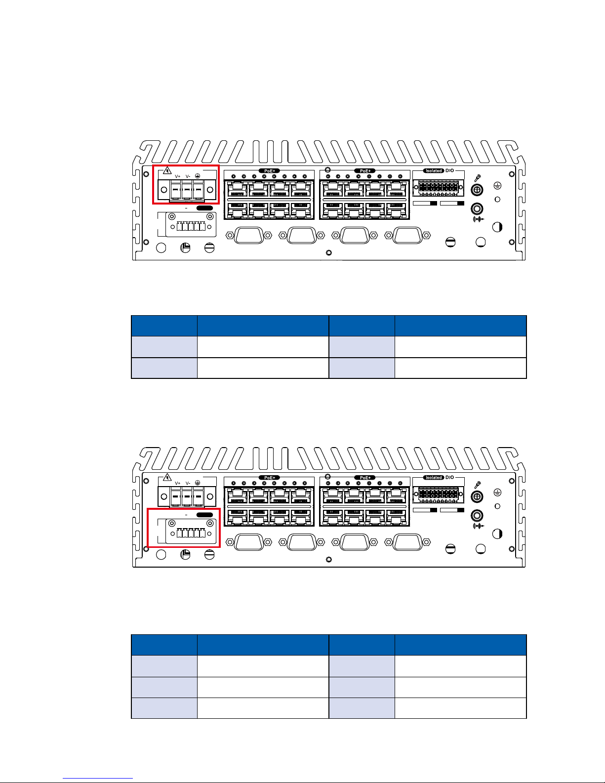
2.3 Rear Panel I/O and Functions
2.3.1 Power Terminal Block
This system supports 6V to 78V DC power input by terminal block in the rear
side. In normal power operation, power LED lightens in solid green. Supports up
to 200V surge protection.
D IPIN 1 ~ 8 DOPIN 11 ~ 18
20 11
10 1
345678910
LAN 3
LAN 4
LAN 5
LAN 6
LAN 7
LAN 8
LAN 9
LAN 10
1112131415161718
LAN 11
LAN 12
LAN 13
LAN 14
LAN 15
LAN 16
LAN 17
LAN 18
COM 1COM 2COM 3COM 4
DC-IN 6~78V
On / OffIGNLED+ LED
Power
Switch
2.3.2 Remote Power On/ O Switch & LED Terminal Block
D IPIN 1 ~ 8 DOPIN 11 ~ 18
20 11
10 1
345678910
LAN 3
LAN 4
LAN 5
LAN 6
LAN 7
LAN 8
LAN 9
LAN 10
1112131415161718
LAN 11
LAN 12
LAN 13
LAN 14
LAN 15
LAN 16
LAN 17
LAN 18
COM 1COM 2COM 3COM 4
DC-IN 6~78V
On / OffIGNLED+ LED
Power
Switch
It is a 5-pin power-on or power-off switch through Phoenix Contact terminal
block. You could turn on or off the system power by using this contact. This
terminal block supports dual function of soft power-on/ power-off (instant off or
delay 4 second), and suspend mode.
Pin No. Denition Pin No. Denition
1 External Power Button V+ 2 External Power Button V-
3 Ignition 4 External Power LED V-
5 External Power LED V+
Pin No. Denition Pin No. Denition
1 V+ 2 V-
3 Chassis Ground
20
GETTING TO KNOW YOUR IVH-9000©Vecow IVH-9000 User Manual
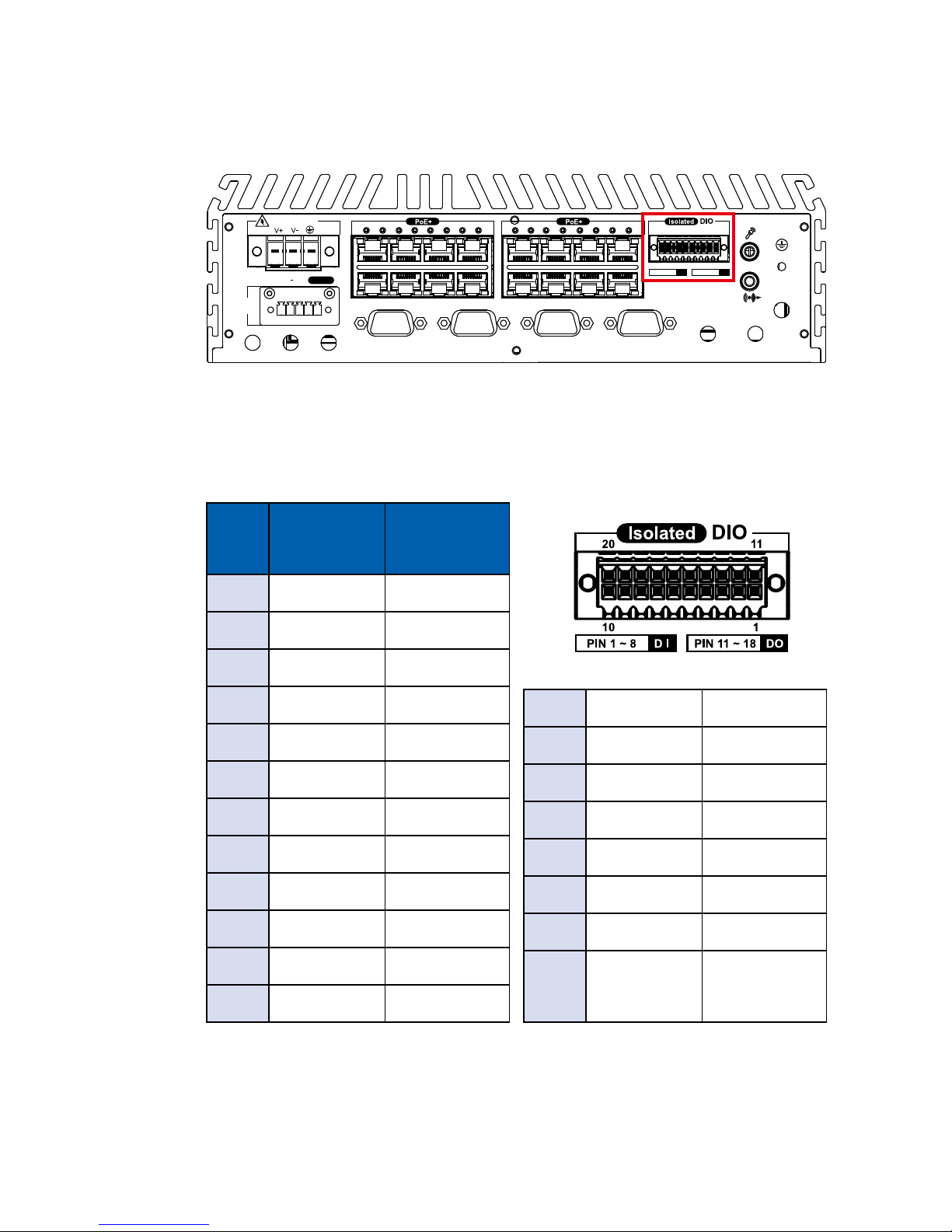
2.3.3 Isolated DIO
There is a 16-bit DIO (8-bit DI, 8-bit DO) connector in the rear side. Each DIO
channel is equipped with a photocoupler for isolated protection. A power buffer
device TPD2007F integrated in 8-bit DO circuit for motors, solenoids, and lamp
driver applications. Please refer to Appendix A for more details.
Pin
No.
Denition Mapping to
SIO GPIO
Function
1 INPUT 0 SIO_GPI80
2 INPUT 1 SIO_GPI81
3 INPUT 2 SIO_GPI82
4 INPUT 3 SIO_GPI83
5 INPUT 4 SIO_GPI84
6 INPUT 5 SIO_GPI85
7 INPUT 6 SIO_GPI86
8 INPUT 7 SIO_GPI87
9 DI_COM -----------
10 GND -----------
11 OUTPUT 0 SIO_GPO70
12 OUTPUT 1 SIO_GPO71
13 OUTPUT 2 SIO_GPO72
14 OUTPUT 3 SIO_GPO73
15 OUTPUT 4 SIO_GPO74
16 OUTPUT 5 SIO_GPO75
17 OUTPUT 6 SIO_GPO76
18 OUTPUT 7 SIO_GPO77
19 N.C. -----------
20 External 6V
to 36V DC
Input
-----------
D IPIN 1 ~ 8 DOPIN 11 ~ 18
20 11
10 1
345678910
LAN 3
LAN 4
LAN 5
LAN 6
LAN 7
LAN 8
LAN 9
LAN 10
1112131415161718
LAN 11
LAN 12
LAN 13
LAN 14
LAN 15
LAN 16
LAN 17
LAN 18
COM 1COM 2COM 3COM 4
DC-IN 6~78V
On / OffIGNLED+ LED
Power
Switch
21
GETTING TO KNOW YOUR IVH-9000
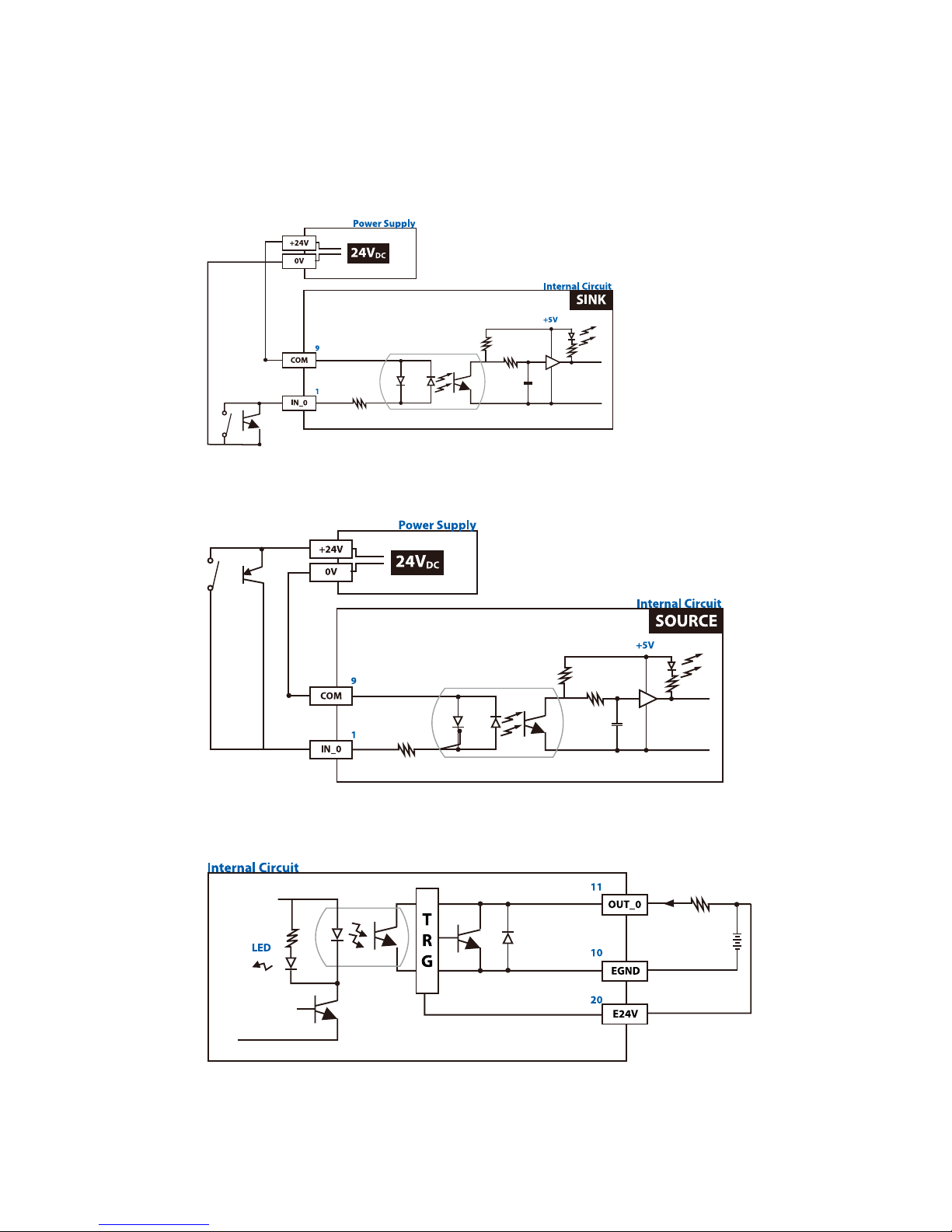
GPI SINK Mode
Isolated GPI input circuit in SINK mode (NPN) is illustrated as follow :
GPI SOURCE Mode
Digital GPI input signal circuit in SOURCE mode (PNP) is illustrated as follow :
GPO SINK Mode
Digital GPO output circuit in SINK mode (NPN) is illustrated as follow :
24V Application Diagram :
22
GETTING TO KNOW YOUR IVH-9000©Vecow IVH-9000 User Manual
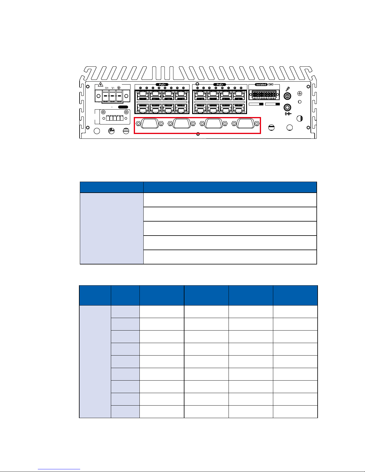
2.3.4 Serial Port
Serial
Port
Pin No. RS-232 RS-422
(5-wire)
RS-422
(9-wire)
RS-485
(3-wire)
1 to 4
1 DCD TXD- TXD- DATA -
2 RXD TXD+ TXD+ D ATA+
3 TXD RXD+ RXD+ -----------
4 DTR RXD- RXD- -----------
5 GND GND GND GND
6 DSR ----------- RTS- -----------
7 RTS ----------- RTS+ -----------
8 CTS ----------- CTS+ -----------
9 RI ----------- CTS- -----------
The pin assignments are listed in the table as follow :
BIOS Setting Function
COM 1 (CN 18)
COM 2 (CN 19)
COM 3 (CN 20)
COM 4 (CN 21)
RS-232
RS-422 (5-wire)
RS-422 (9-wire)
RS-485
RS-485 w/z auto-ow control
Serial port 1 to 4 (COM 1 to 4) can be congured for RS-232, RS-422, or RS485 with auto ow control communication. The default denition of COM 1 and
COM 2 is RS-232, if you want to change to RS-422 or RS-485, you can nd the
setting in BIOS.
D IPIN 1 ~ 8 DOPIN 11 ~ 18
20 11
10 1
345678910
LAN 3
LAN 4
LAN 5
LAN 6
LAN 7
LAN 8
LAN 9
LAN 10
1112131415161718
LAN 11
LAN 12
LAN 13
LAN 14
LAN 15
LAN 16
LAN 17
LAN 18
COM 1COM 2COM 3COM 4
DC-IN 6~78V
On / OffIGNLED+ LED
Power
Switch
23
GETTING TO KNOW YOUR IVH-9000
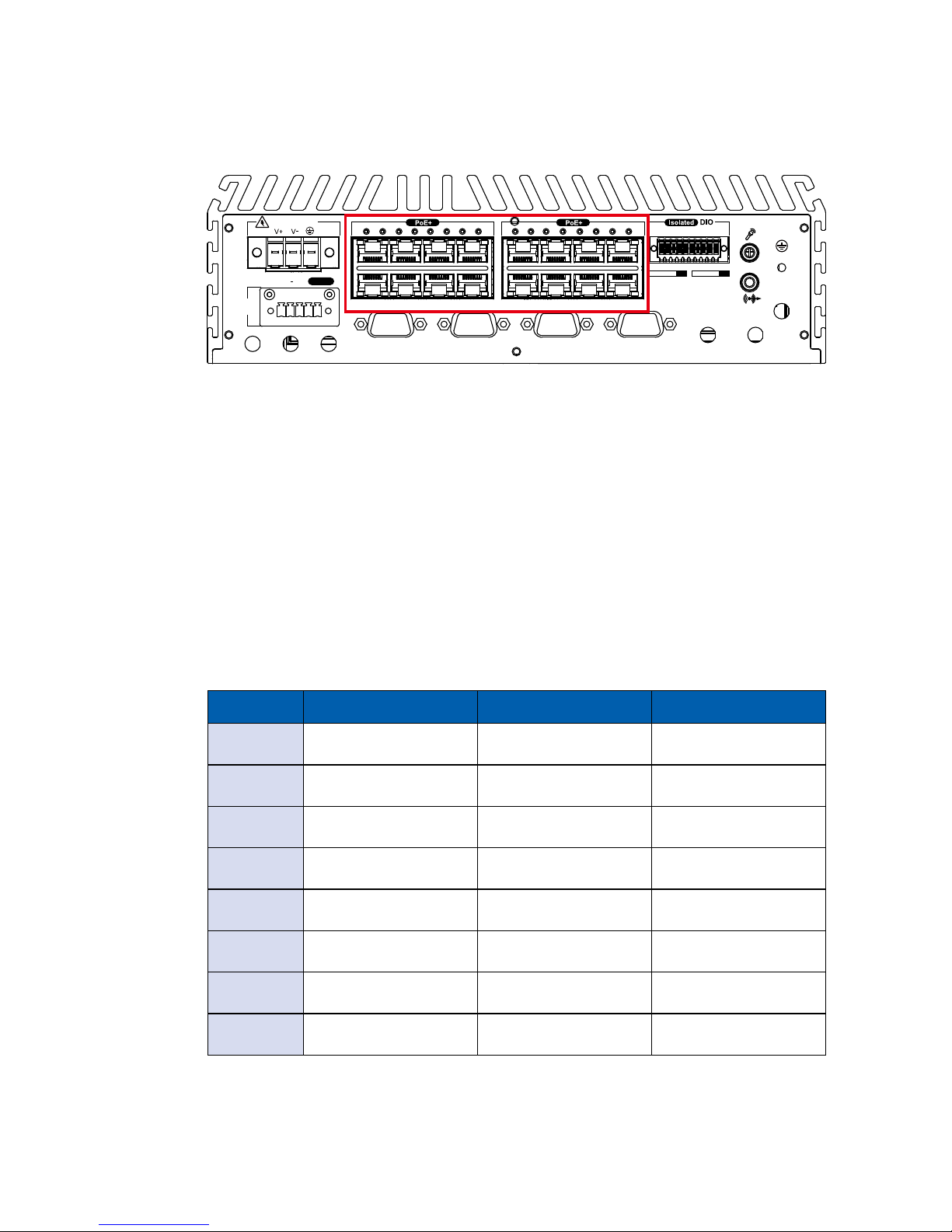
2.3.6 PoE (Power over Ethernet) Ports
There are 16 RJ45 connectors in the rear side. It supports IEEE 802.3at
(PoE+) Power over Ethernet (PoE) connection delivering up to 25.5W/ 48V per
port(Total 160W) and 1000BASE-T gigabit data signals over standard Ethernet
Cat 5/ Cat 6 cable.
Each PoE connection is powered by Intel® I350 Gigabit Ethernet controller and
independent PCI express interface to connect with multi-core processor for
network and data transmit optimization. Only when PoE port starts to supply
power to power devices, the dedicated LED will be lightened.
PS. Suggest to use 160W PoE when power input is over 12V, use 80W PoE
when power input is over 9V
D IPIN 1 ~ 8 DOPIN 11 ~ 18
20 11
10 1
345678910
LAN 3
LAN 4
LAN 5
LAN 6
LAN 7
LAN 8
LAN 9
LAN 10
1112131415161718
LAN 11
LAN 12
LAN 13
LAN 14
LAN 15
LAN 16
LAN 17
LAN 18
COM 1COM 2COM 3COM 4
DC-IN 6~78V
On / OffIGNLED+ LED
Power
Switch
Pin No. 10/ 100 Mbps 1000 Mbps PoE
1 E_TX+ MDI0_P PoE+
2 E_TX- MDI0_N PoE+
3 E_RX+ MDI1_P PoE-
4 ---- MDI2_P ----
5 ----- MDI2_N ----
6 E_RX- MDI1_N PoE-
7 ----- MDI3_P ----
8 ------ MDI3_N ----
The pin-outs of LAN 3 and LAN 18 are listed as follows:
 Loading...