

Page 1

USER
Manual
USER
Manual
1.4.0 Edition 20190227
3.5” Embedded Single Board Computer with Intel Atom® x7-E3950,
2 GigE LAN w/IEEE 1588, Isolated COM, TPM 2.0, -40°C to 85°C
EMBC-2000
Page 2
ii
©Vecow EMBC-2000 User Manual
Version Date Page Description Remark
0.10 11/14/2018 All Preliminary Release
1.00 11/22/2018 All Ofcial Release
1.10 01/19/2019 2, 32 Update
1.20 01/20/2019 19 Update
1.30 01/25/2019 11 Update
1.40 02/27/2019 8, 19, 23, 24, 28, 29 Update
Record of Revision
Page 3

iii
©Vecow EMBC-2000 User Manual
This manual is released by Vecow Co., Ltd. for reference purpose only. All
product offerings and specications are subject to change without prior notice. It
does not represent commitment of Vecow Co., Ltd. Vecow shall not be liable for
direct, indirect, special, incidental, or consequential damages arising out of the
use of the product; documentation; or for any infringements upon the rights of
third parties, which may result from such use.
Disclaimer
This equipment has been tested and found to comply with the limits for a Class
A digital device, pursuant to part 15 of the FCC Rules. These limits are designed
to provide reasonable protection against harmful interference when the
equipment is operated in a commercial environment. This equipment generates,
uses, and can radiate radio frequency energy, and if it is not installed and used
in accordance with the instruction manual, it may cause harmful interference to
radio communications. Operation of this equipment in a residential area is likely
to cause harmful interference in which case the user will be required to correct
the interference at his own expense.
FCC
The products described in this manual comply with all applicable European
Union (CE) directives if it has a CE marking. For computer systems to
remain CE compliant, only CE-compliant parts may be used. Maintaining CE
compliance also requires proper cable and cabling techniques.
CE
Declaration of Conformity
This document contains proprietary information protected by copyright. No part
of this publication may be reproduced in any form or by any means, electric,
photocopying, recording or otherwise, without prior written authorization
by Vecow Co., Ltd. The rights of all the brand names, product names and
trademarks belong to their respective owners.
Copyright and Trademarks
Page 4
iv
©Vecow EMBC-2000 User Manual
Part Number Description
EMBC-2000
3.5” SBC, onboard Intel Atom® x7-E3950 processor (Apollo Lake-I),
2 GigE LAN with IEEE 1588 (PTP), 6 USB, 2 Mini PCIe, 1 SIM,
4 COM w/2 isolated, 16 GPIO
Order Information
Part Number Description
61-13Q1009-0DA COM Port Cable
61-193102U-156 USB 2.0 Cable
61-13T10LM-3CG Audio Cable
61-13B0707-386 SATA Data Cable
61-13P0430-08A SATA Power Cable
61-13S33KM-3CG KB/MS Cable
WRP-101 Wide-Range 9V to 36V DC-in Power Module
EMBC-2000
Heat Spreader
Heat Spreader for EMBC-2000 Use
Order Accessories
Page 5

v
©Vecow EMBC-2000 User Manual
Table of Contents
CHAPTER 1 GENERAL INTRODUCTION 1
1.1 Overview 1
1.2 Features 2
1.3 Product Specication 2
1.3.1 Specications of EMBC-2000 2
1.4 Mechanical Dimension 5
1.4.1 Dimensions of EMBC-2000 SBC 5
1.4.2 Dimensions of EMBC-2000 Heat Spreader 5
1.4.3 Dimensions of EMBC-2000 SBC + Heat Spreader 5
CHAPTER 2 GETTING TO KNOW YOUR EMBC-2000 6
2.1 Packing List 6
2.2 Main Board Expansion Connectors 8
2.3 Main Board Jumper Settings 27
CHAPTER 3 SETUP 30
3.1 Installing Heat Spreader 30
3.2 Installing DDR3L Module 32
3.3 Installing Mini PCIe Card 33
3.4 Installing SIM Card 35
Page 6

vi
©Vecow EMBC-2000 User Manual
CHAPTER 4 BIOS SETUP 37
4.1 Entering Setup 37
4.2 Main Menu 38
4.3 Advanced 38
4.4 Chipset 44
4.5 Security 50
4.6 Boot 51
4.7 Save & Exit 52
APPENDIX A : Isolated DIO Guide 53
APPENDIX B : Software Functions 56
APPENDIX C : Power Consumption 58
APPENDIX E : Supported Memory & Storage List 60
Page 7

1
©Vecow EMBC-2000 User Manual
GENERAL INTRODUCTION
GENERAL INTRODUCTION
1.1 Overview
EMBC-2000 3.5” Embedded Single Board Computer is an all-in-one, high
performance, compact, and energy-saving embedded engine in the market.
Powered by quad-core Intel Atom® x7-E3950 Processor (Apollo Lake-I), single
DDR3L SO-DIMM supports up to 8GB memory; Advanced Intel® HD graphics
505 supports DirectX 12, OpenGL 4.3 and OpenCL 2.1 API, up to 4K resolution;
Vecow EMBC-2000 delivers more than 150% system performance improved
and up to 300% graphics performance enhanced than the embedded engine
powered by the former generation Intel Atom® E3845 SoC.
Featured with VGA, HDMI and dual-channel 24-bit LVDS display interface,
dual GigE LAN support IEEE 1588 Precision Time Protocol (PTP), 4 COM
RS-232/422/485 with 2 Isolated, 6 USB, 1 SIM socket for WiFi/4G/3G/LTE/
GPRS/UMTS, 2 Mini PCIe, 1 SATA III, 16 GPIO, TPM 2.0 supported, fanless
-40°C to 85°C extended operating temperature, optional supports 9V to 36V
wide range DC power input, Vecow EMBC-2000 Embedded Single Board
Computer integrates outstanding performance, lower power consumption, smart
manageability, mobile availability, exible conguration and rugged reliability for
low-prole embedded applications.
Vecow EMBC-2000 Embedded Single Board Computer delivers outstanding
system performance, compact integrated functions, smart manageability, mobile
availability, trusted reliability and exible expansion features for your Machine
Vision, Smart Manufacturing, Factory Automation, ITS (Intelligent Transportation
System), Digital Signage, Public Infotainment, POI/POS or any IIoT/Industry 4.0
applications.
1
Page 8
2
©Vecow EMBC-2000 User Manual
GENERAL INTRODUCTION
1.2 Features
• Quad Core Intel Atom® x7-E3950 SoC (Apollo Lake-I) supports lower power
consumption, up to 3 independent Ultra HD displays
• Supports DDR3L 1866MHz Memory, up to 8GB
• Fanless, -40°C to 85°C Operating Temperature
• Onboard Lockable HDMI, VGA, 24-bit LVDS display interface, up to 4K resolution
• Dual Independent Gigabit LAN, IEEE 1588 (PTP) supported
• 4 COM RS-232/422/485, 2 with Isolated protection
• SIM Socket for WiFi/4G/3G/ LTE/GPRS/UMTS
• 6 USB, 2 Mini PCIe, 1 SATA III, 16 GPIO
• TPM 2.0 supported
• 12V DC Power Input, optional supports 9V to 36V wide range DC Power Input
• Easy to customize for low-profile system applications
• Optional for M.2/Mini PCIe/PCI/PCIe expansions
1.3 Product Specication
1.3.1 Specications of EMBC-2000
System
Processor Intel Atom® x7-E3950 processor (Apollo Lake-I)
BIOS AMI
SIO IT8786E
Memory 1 DDR3L 1866MHz SO-DIMM, up to 8GB (Non-ECC)
OS Windows 10, Linux
Graphics
Processor Intel® HD Graphics 505
Interface • HDMI : Up to 3840 x 2160 @30Hz (Lockable)
• VGA : Up to 1920 x 1440 @60Hz
• LVDS : Dual channel 24-bit, up to 1920 x 1200
Page 9
3
©Vecow EMBC-2000 User Manual
GENERAL INTRODUCTION
Audio
Audio Codec Realtek ALC892, 5.1 Channel HD Audio
Audio Interface 1 Mic-in, 1 Line-out
Ethernet
LAN 1 Intel® I210 GigE LAN supports IEEE 1588
LAN 2 Intel
®
I210 GigE LAN supports IEEE 1588
I/O Interface
Front I/O • 2 RJ45 Connector
• 2 USB 3.0 Connector
• 2 USB 2.0 Connector
• 1 Lockable HDMI Connector
• 1 VGA Connector
• 1 Power Button
• 1 Reset Button
Internal I/O • 1 ATX 4-Pin Power Connector
• 1 DDR3L SO-DIMM Socket
• 1 USB 2.0 Connector for 2 USB Port
• 4 COM RS-232/422/485 Connector (2 with isolation)
• 2 10-pin Box Header for GPIO
• 1 Mic-in
• 1 Line-out
• 1 LVDS Connector
• 1 LVDS Backlight Connector
• 2 Mini PCIe Connector (1 co-lay with mSATA)
• 1 SIM Card Socket
• 1 SATA Connector
• 1 SATA Power Connector
• 1 PCIe Slot (Optional)
• 1 Fan Connector
• 1 LPC Debug Header
• 1 Reset Header
• 1 Power Header
• 1 Battery Header
Storage
SATA 1 SATA III (6Gbps)
mSATA 1 SATA III (Mini PCIe type, 6Gbps)
Storage Device 1 2.5" SSD/HDD bracket
Expansion
Mini PCIe 2 Mini PCIe Socket :
• 1 Mini PCIe for PCIe/USB/SIM Card
• 1 Mini PCIe for PCIe/USB/Optional mSATA
Page 10
4
©Vecow EMBC-2000 User Manual
GENERAL INTRODUCTION
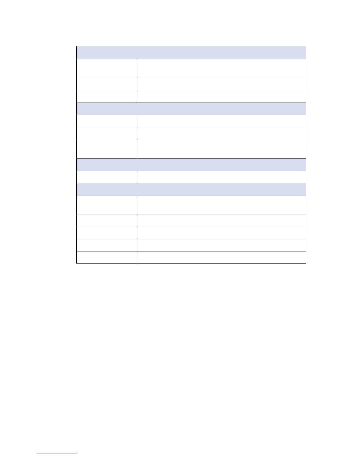
Power
Power Input • Single 12V DC Power Input
• 9V to 36V, DC-in (Optional, via Power Module)
Power Interface ATX Power Connector
Remote Switch 2-pin Terminal Block (Optional)
Others
TPM Optional Inneon SLB9665 supports TPM 2.0, LPC interface
Watchdog Timer Reset : 1 to 255 sec./min. per step
HW Monitor Monitoring temperature, voltages. Auto throttling control when
CPU overheats.
Mechanical
Dimension (W) 102mm x (L) 146mm x (H) 44mm (4.0" x 5.8")
Environment
Operating
Temperature
-40°C to 85°C (-40°F to 185°F)
Storage Temperature -40°C to 85°C (-40°F to 185°F)
Humidity 5% to 95% Humidity, non-condensing
Relative Humidity 95% at 85°C
EMC CE, FCC
Page 11
5
©Vecow EMBC-2000 User Manual
GENERAL INTRODUCTION
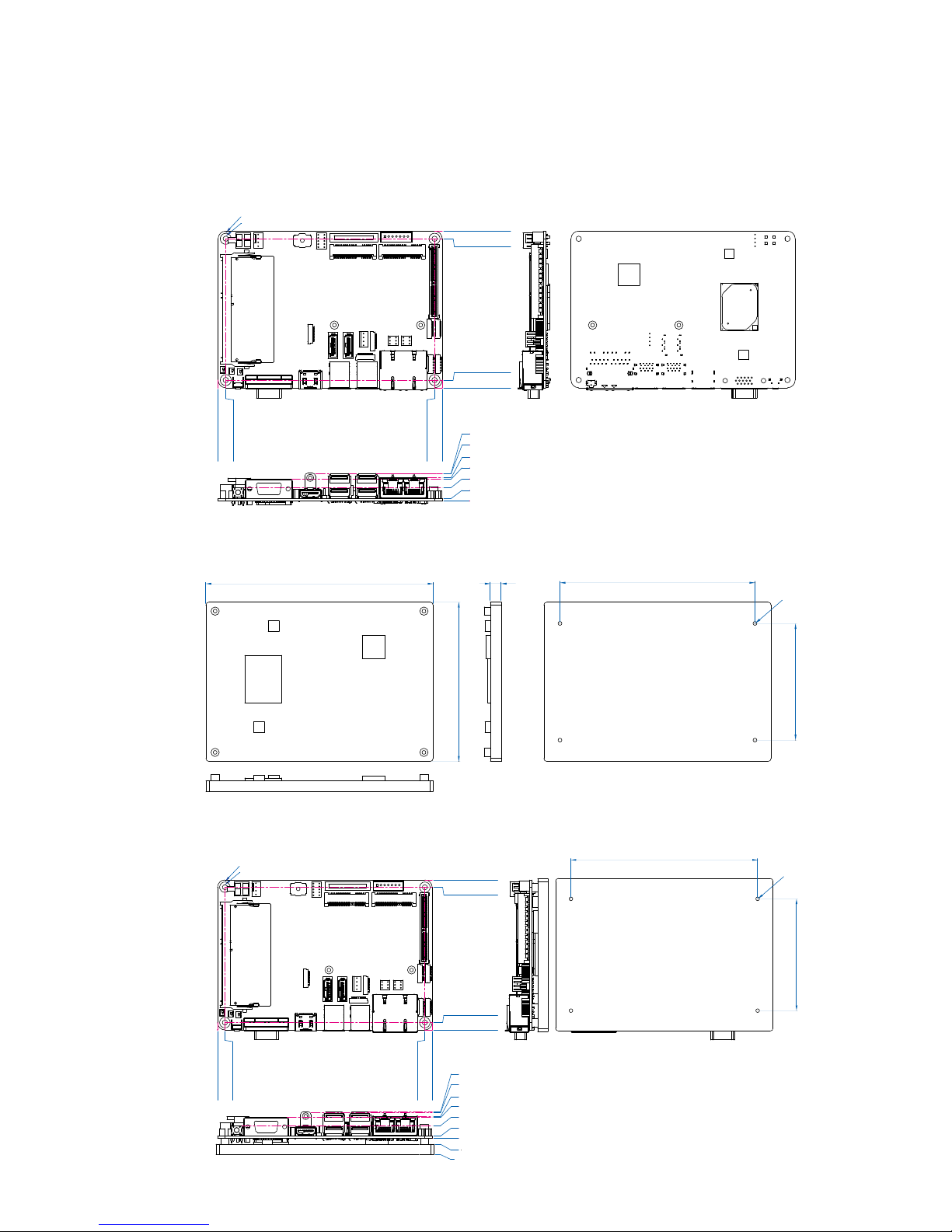
1.4 Mechanical Dimension
1.4.1 Dimensions of EMBC-2000 SBC
0.0 (0.00")
1.6 (0.06")
8.7 (0.34")
14.2 (0.56")
15.1 (0.59")
17.7 (0.70")
17.9 (0.71")
0.0 (0.00")
5.0 (0.20")
141.0 (5.55")
146.0 (5.75")
0.0 (0.00")
5.0 (0.20")
97.0 (3.82")
102.0 (4.02")
ø3.5 (ø0.14")
ø7.2 (ø0.28")
Unit : mm (inch)
1.4.2 Dimensions of EMBC-2000 Heat Spreader
Unit : mm (inch)
148.0 (5.83")
103.8 (4.09")
7.0 (0.28")
127.0 (5.00")
76.0 (2.99")
4-#6-32
4.0 (0.16”)
1.4.3 Dimensions of EMBC-2000 SBC + Heat Spreader
Unit : mm (inch)
127.0 (5.00")
76.0 (2.99")
4-#6-32
4.0 (0.16”)
0.0 (0.00")
5.0 (0.20")
141.0 (5.55")
146.0 (5.75")
0.0 (0.00")
5.0 (0.20")
97.0 (3.82")
102.0 (4.02")
ø3.5 (ø0.14")
ø7.2 (ø0.28")
0.0 (0.00")
1.6 (0.06")
8.7 (0.34")
14.2 (0.56")
15.1 (0.59")
17.7 (0.70")
17.9 (0.71")
-4.0 (-0.16")
-11.0 (-0.43")
Page 12
6
©Vecow EMBC-2000 User Manual
GETTING TO KNOW YOUR EMBC-2000
2
GETTING TO KNOW YOUR EMBC-2000
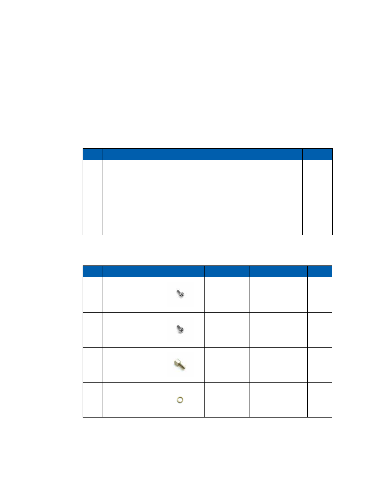
2.1 Packing List
Item Description Qty
1 EMBC-2000 SBC 1
2 Driver/ User Manual DVD 1
3 Screws & Cables (Below)
Item Description Outlook Usage P/N Qty
1
PHILLPIS
M2.5x6L,Ni
Mini PCIe 53-2426906-30B 2
2
PHILLPIS
M3x6L,Ni+Ny
USB 2.0
Cable
53-2426206-80B 4
3 HEX #4-40x
COM Cable 53-I000172-001 8
4 Audio NUT
Audio Cable N/A 2
Page 13
7
©Vecow EMBC-2000 User Manual
GETTING TO KNOW YOUR EMBC-2000
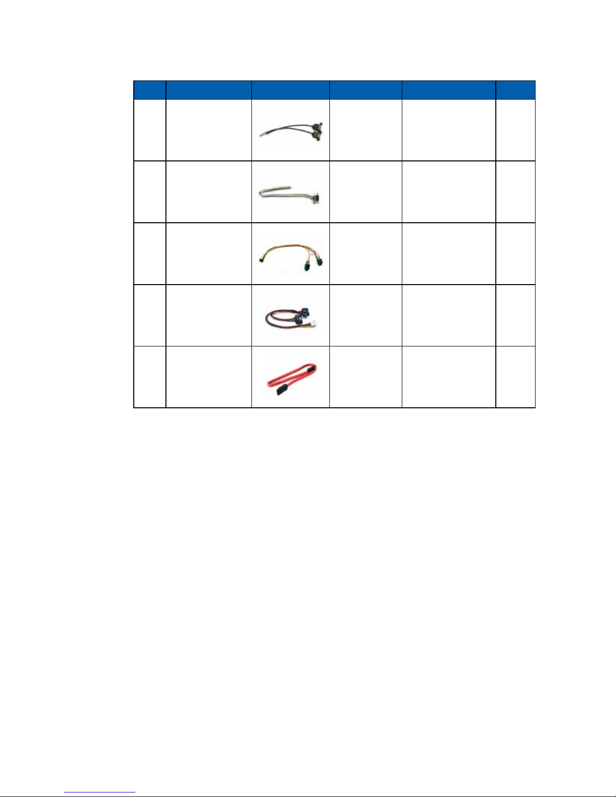
Item Description Outlook Usage P/N Qty
5 USB 2.0 Y-cable
USB 2.0
Connector
61-193102U-156 1
6 COM Cable
COM
Connector
61-13Q1009-0DA 2
7 Audio Cable
Audio
Connector
61-13T10LM-3CG 1
8
SATA Power
Y-cable
SATA Power
Connector
61-13P0430-08A 1
9
SATA Data
Cable
SATA Date
Connector
61-13B0707-386 1
Page 14
8
©Vecow EMBC-2000 User Manual
GETTING TO KNOW YOUR EMBC-2000
2.2 Main Board Expansion Connectors
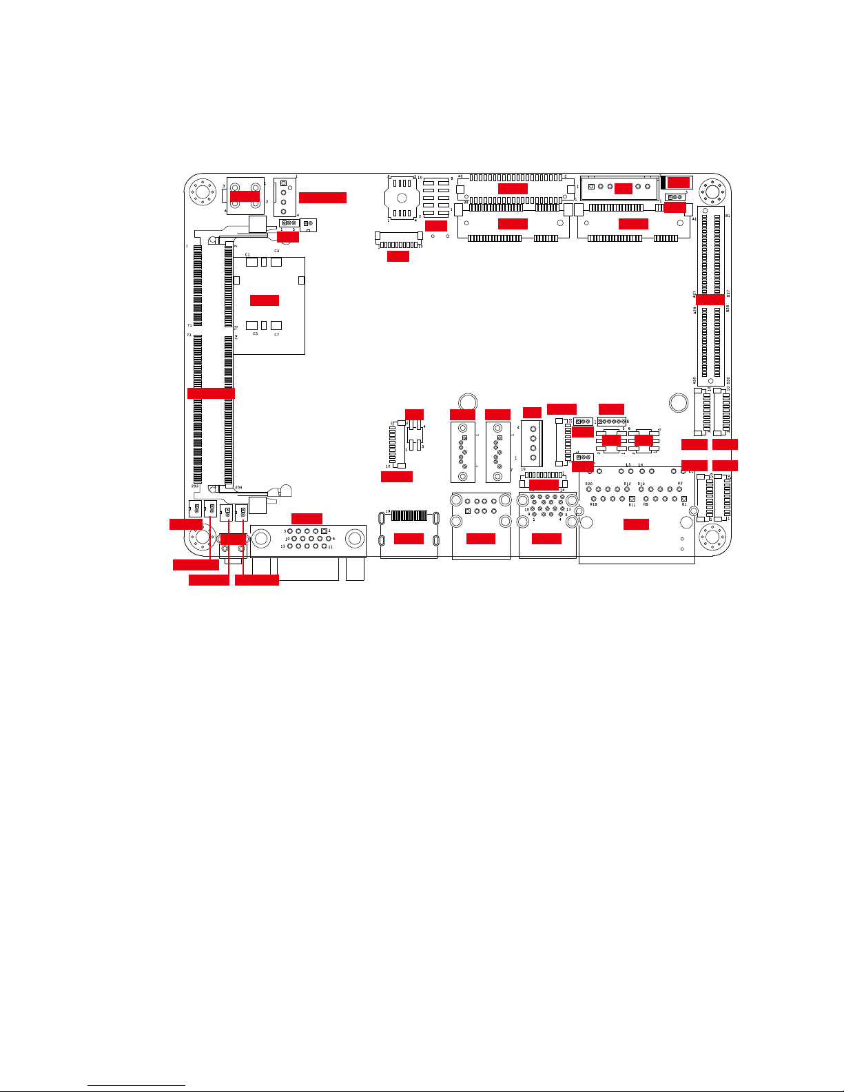
2.2.1 EMBC-2000 Main Board Pin Header Location
J3
CN4
CON1
CN 15 CN 13
J4
CN 16
CN8 CN9
CN6 CN7
J5J6
JPS2
CN5
CN11CN12
CN1 CN2
J1
JDIO2
JDIO1
CN10
JUSB1
VGA2
JHDD1
SO-DIMM1
CN14
CN18
CPU_FAN1
JPWBTN1
JRESET1 JSTATUS1
JP6
JP5
JP2
JP3
JP7
JP4
SW3
Page 15
9
©Vecow EMBC-2000 User Manual
GETTING TO KNOW YOUR EMBC-2000
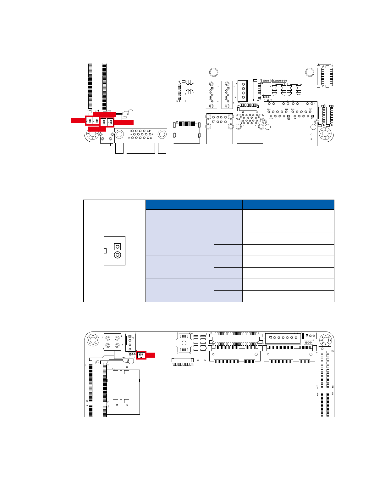
These pin headers can be used as a backup for following functions, hard drive
LED indicator, reset button, power LED indicator, and power-on/off button, which
already be accessed by the front and top panels. The pinouts of Miscellaneous
port are listed in following table :
Group Pin No. Description
JPWBTN
1 GND
2 FP_PWR_BTN_IN
JRESET
1 GND
2 FP_RST_BTN_N
JSTATUS
1 PWR_LED_N
2 PWR_LED_P
JHDD
1 HDD_LED_N
2 HDD_LED_P
1
2.2.3 Battery
BAT
The EMBC-2000 real-time clock is powered by a lithium battery. It is equipped
with Panasonic BR2032 190mAh lithium battery. It is recommended that you
should not replace the lithium battery on your own. If the battery needs to be
changed, please contact the Vecow RMA service team.
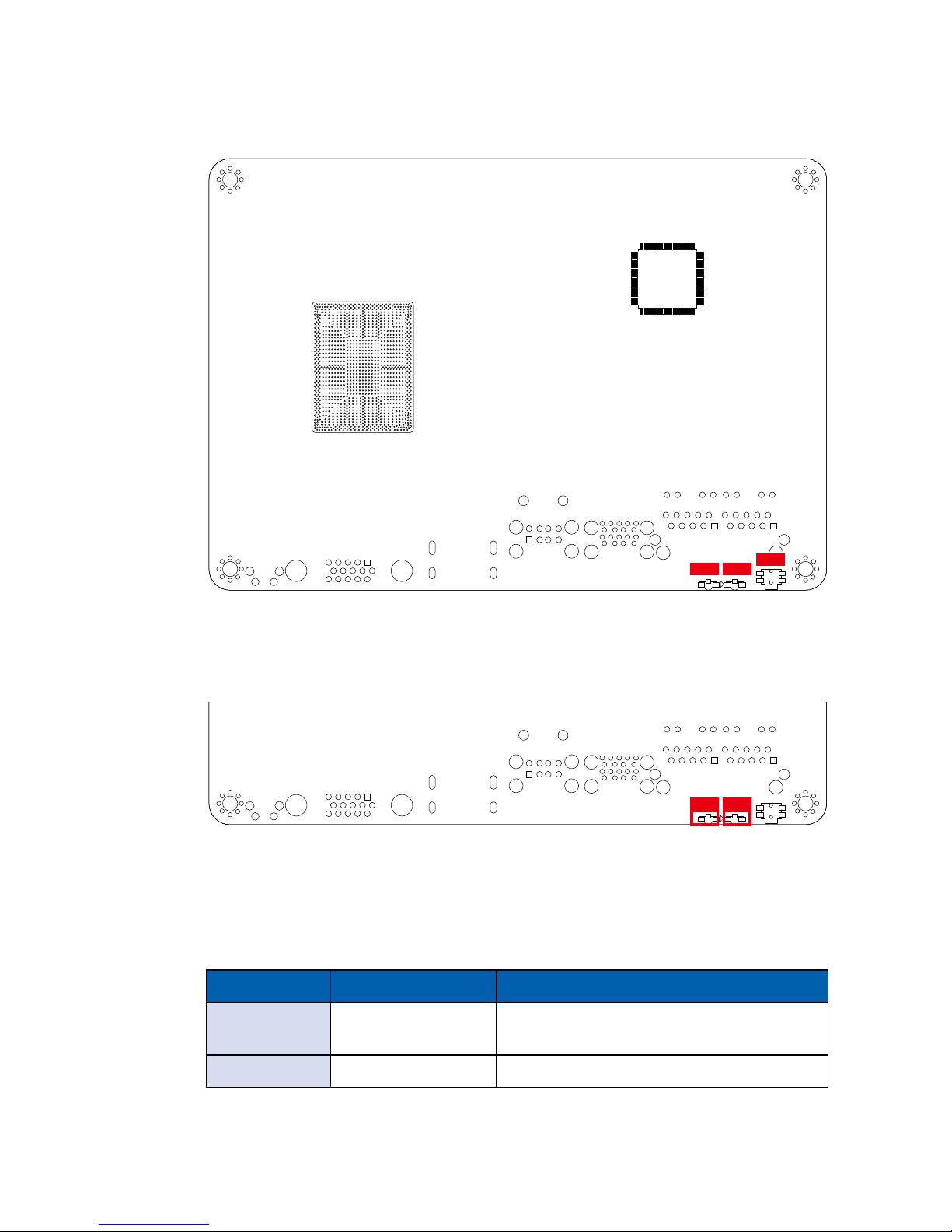
2.2.2 JPWBTN, JRESET, JSTATUS, JHDD : Miscellaneous Pin Header
JHDD1
JPWBTN1
JRESET1
JSTATUS1
Page 16
10
©Vecow EMBC-2000 User Manual
GETTING TO KNOW YOUR EMBC-2000
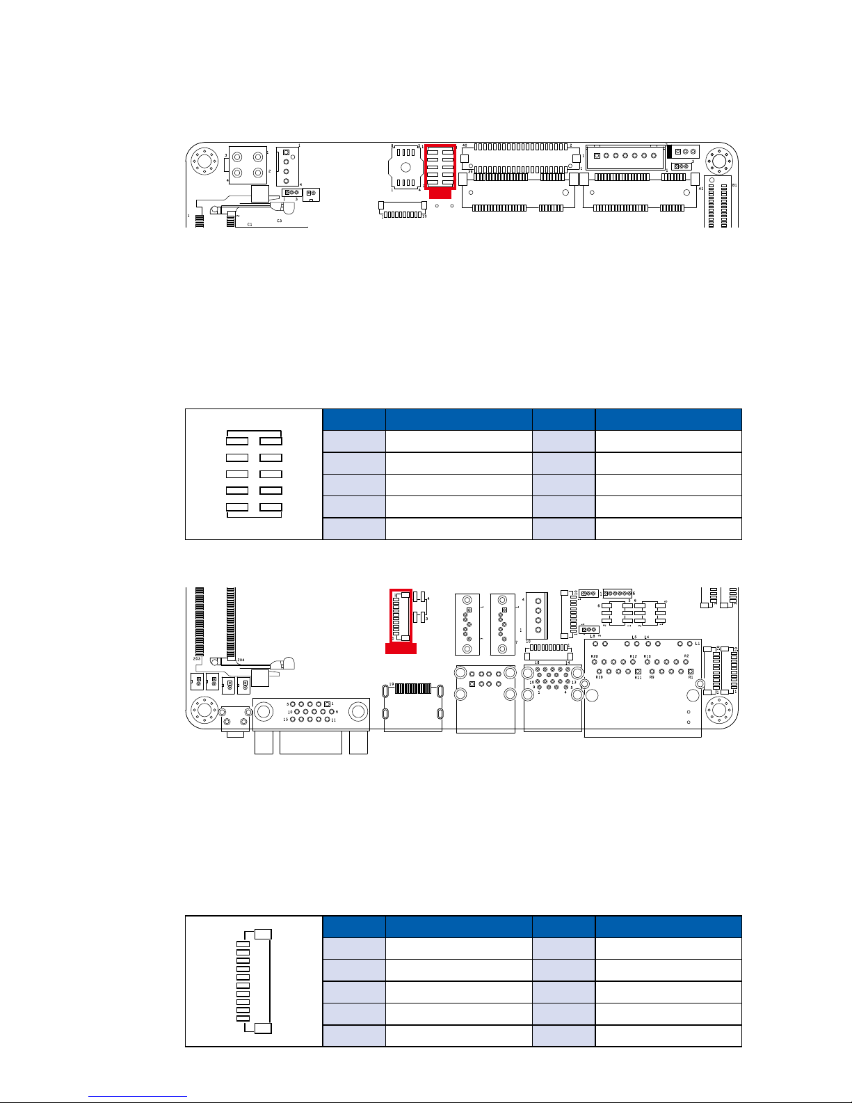
2.2.4 CN4 : Audio Connector
2.2.5 JUSB1 : Internal USB 2.0 Connector
EMBC-2000 main board provides maximum eight expansion USB ports. The
USB interface supports 480Mbps transfer rate which is complied with high
speed USB specication Rev. 2.0.
The USB interface is accessed through one 10-pin JST 1.0mm connector. You
will need an adapter cable while using a standard USB connector. The adapter
cable is a 10-pin connector on one end and a USB connector on the other. The
pin assignments of JUSB1 are listed in the following table :
Pin No. Denition Pin No. Denition
1 USB_VCC 2 USB_VCC
3 USB_VCC 4 USB_D_4N
5 USB_D_4P 6 USB_D_5N
7 USB_D_5P 8 GND
9 GND 10 GND
1
10
JUSB1
There are 3 audio connectors, Mic-in, Line-in and Line-out, in the top side of
EMBC-2000. Onboard Realtek ALC892 audio codec supports 5.1 channel HD
audio and fully complies with Intel
®
High Denition Audio (Azalia) specications.
To utilize the audio function in Windows platform, you need to install
corresponding drivers for both Intel
®
Apollo lake chipset and Realtek ALC892
codec. Please refer to Chapter 4 for more details of driver installation.
The pinouts of Audio port are listed in following table :
Pin No. Denition Pin No. Denition
1 A_z_MIC1-L 2 GND_A
3 A_z_MIC1-R 4 GND_EARTH
5 A_z_LINEO-R 6 A_z_LINEI-R
7 F_IO_SENSE 8 GND_EARTH
9 A_z_LINEO-L 10 A_z_LINEI-L
10 9
2 1
CN4
Page 17
11
©Vecow EMBC-2000 User Manual
GETTING TO KNOW YOUR EMBC-2000
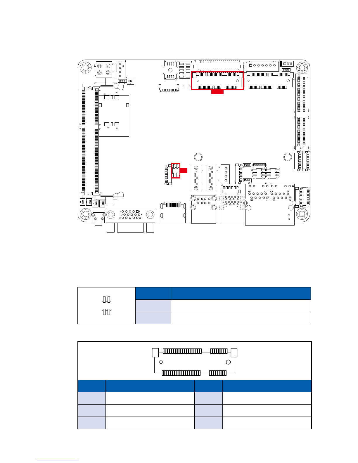
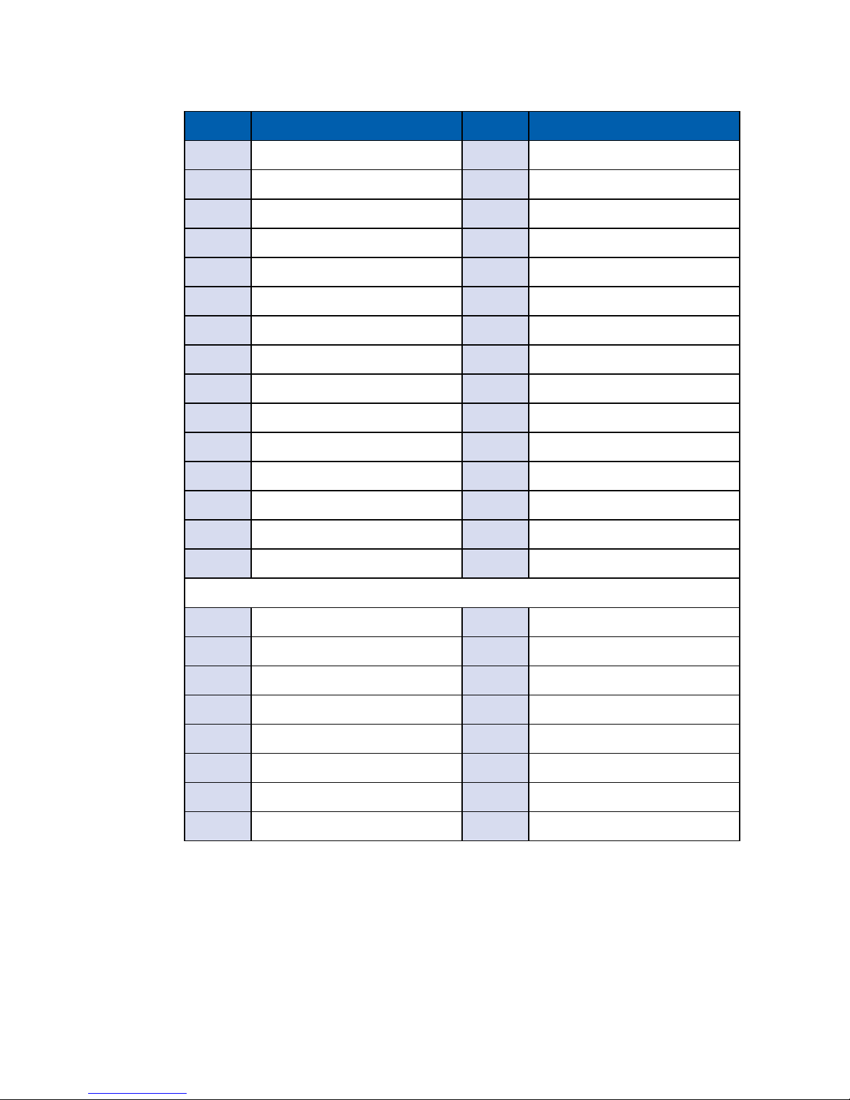
2.2.6 JP5, CN15 : Mini PCIe, mSATA
Both mSATA and Mini PCIe share the same form factor and similar electrical
pinout assignments on their connectors. You can adjust JP5 to choose mSATA
or Mini PCIe function. The pin assignments of CN15 and JP5 are listed in the
following table :
JP5
Pin No. Function
1-3/2-4 mSATA
NC Mini PCIe
CN15
Pin No. Signal Name Pin No. Signal Name
51 Reserved 52 +3.3Vaux
49 Reserved 50 GND
47 Reserved 48 +1.5V
2 4
1 3
1
JP5
CN 15
Page 18
12
©Vecow EMBC-2000 User Manual
GETTING TO KNOW YOUR EMBC-2000
Pin No. Signal Name Pin No. Signal Name
45 Reserved 46 Reserved
43 Status 44 Reserved
41 +3.3Vaux 42 Reserved
39 +3.3Vaux 40 GND
37 GND 38 USB_D+
35 GND 36 USB_D-
33 PETp0 34 GND
31 PETn0 32 SMB_DATA
29 GND 30 SMB_CLK
27 GND 28 +1.5V
25 PERp0 26 GND
23 PERn0 24 +3.3Vaux
21 GND 22 PERST#
19 Reserved 20 reserved
17 Reserved 18 GND
Mechanical Key
15 GND 16 UIM_VPP
13 REFCLK+ 14 UIM_RESET
11 REFCLK- 12 UIM_CLK
9 GND 10 UIM_DATA
7 CLKREQ# 8 UIM_PWR
5 Reserved 6 1.5V
3 Reserved 4 GND
1 WAKE# 2 3.3Vaux
Page 19

13
©Vecow EMBC-2000 User Manual
GETTING TO KNOW YOUR EMBC-2000
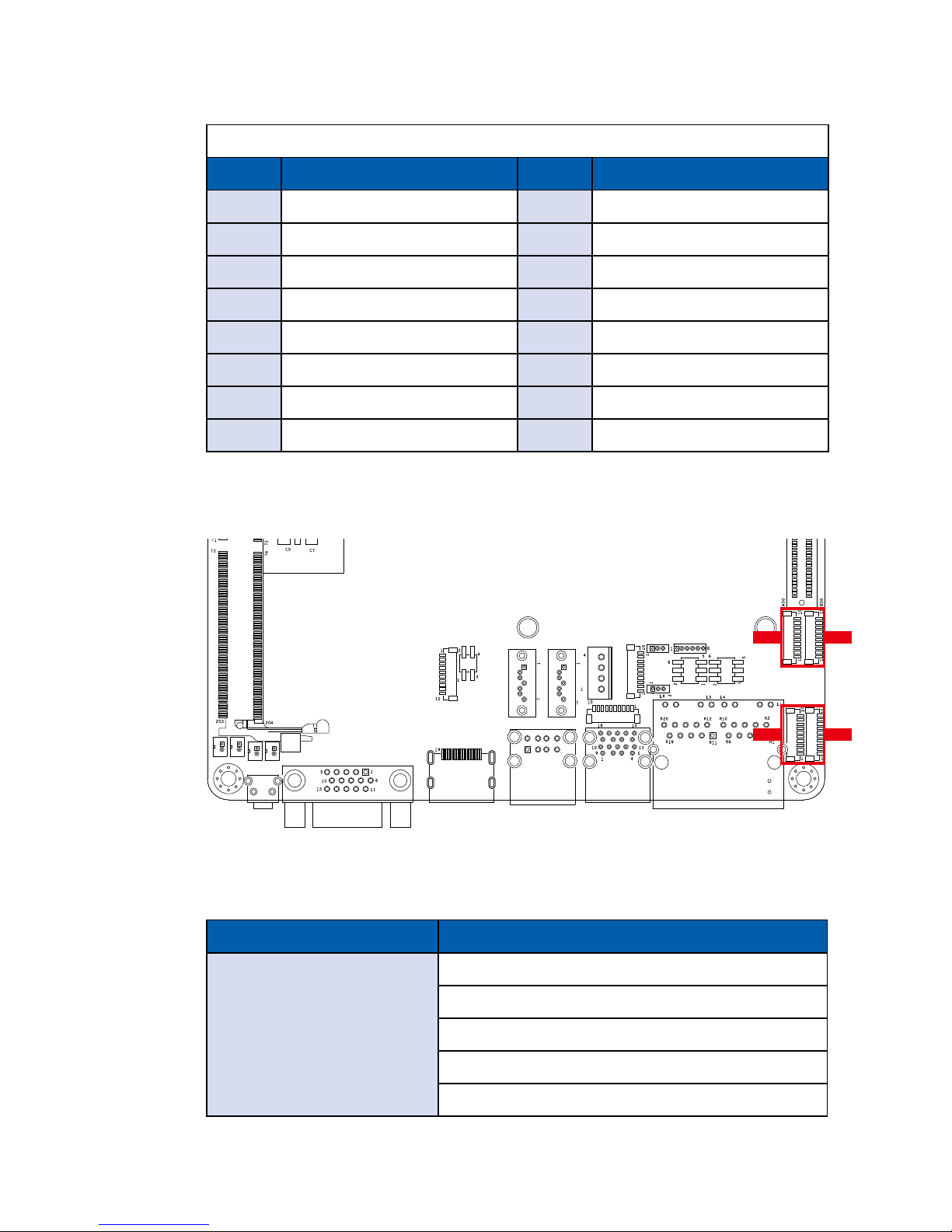
2.2.7 CN13, SIM : Mini PCIe
Note : The SIM card socket does not support hot-plug. Please make sure to
unplug the system power before inserting the SIM card(s).
The pin assignments of CN13 are listed in the following table :
Pin No. Signal Name Pin No. Signal Name
51 Reserved 52 +3.3Vaux
49 Reserved 50 GND
47 Reserved 48 +1.5V
45 Reserved 46 Reserved
43 GND 44 Reserved
41 +3.3Vaux 42 Reserved
39 +3.3Vaux 40 GND
37 GND 38 USB_D+
35 GND 36 USB_D-
33 PETp0 34 GND
31 PETn0 32 SMB_DATA
29 GND 30 SMB_CLK
27 GND 28 +1.5V
25 PERp0 26 GND
23 PERn0 24 +3.3Vaux
21 GND 22 PERST#
19 Reserved 20 Reserved
17 Reserved 18 GND
1
CN 13
Page 20
14
©Vecow EMBC-2000 User Manual
GETTING TO KNOW YOUR EMBC-2000
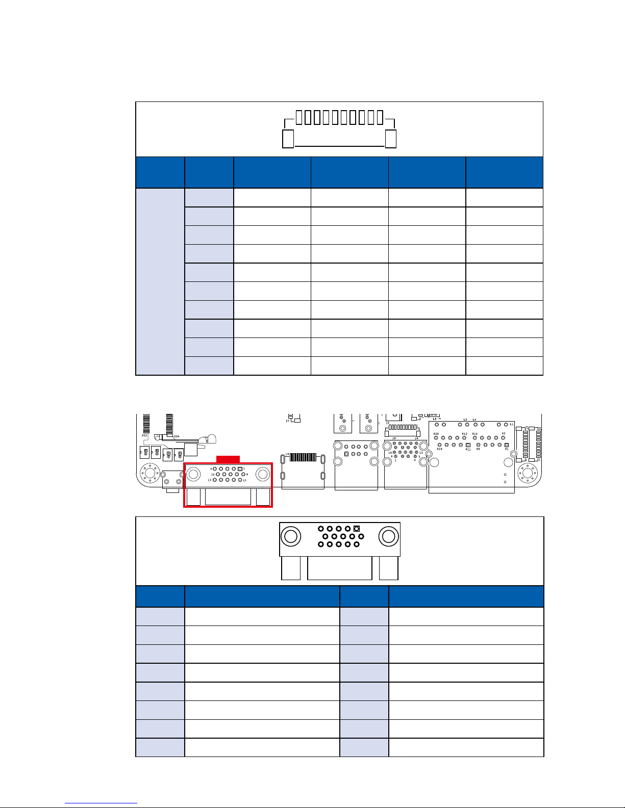
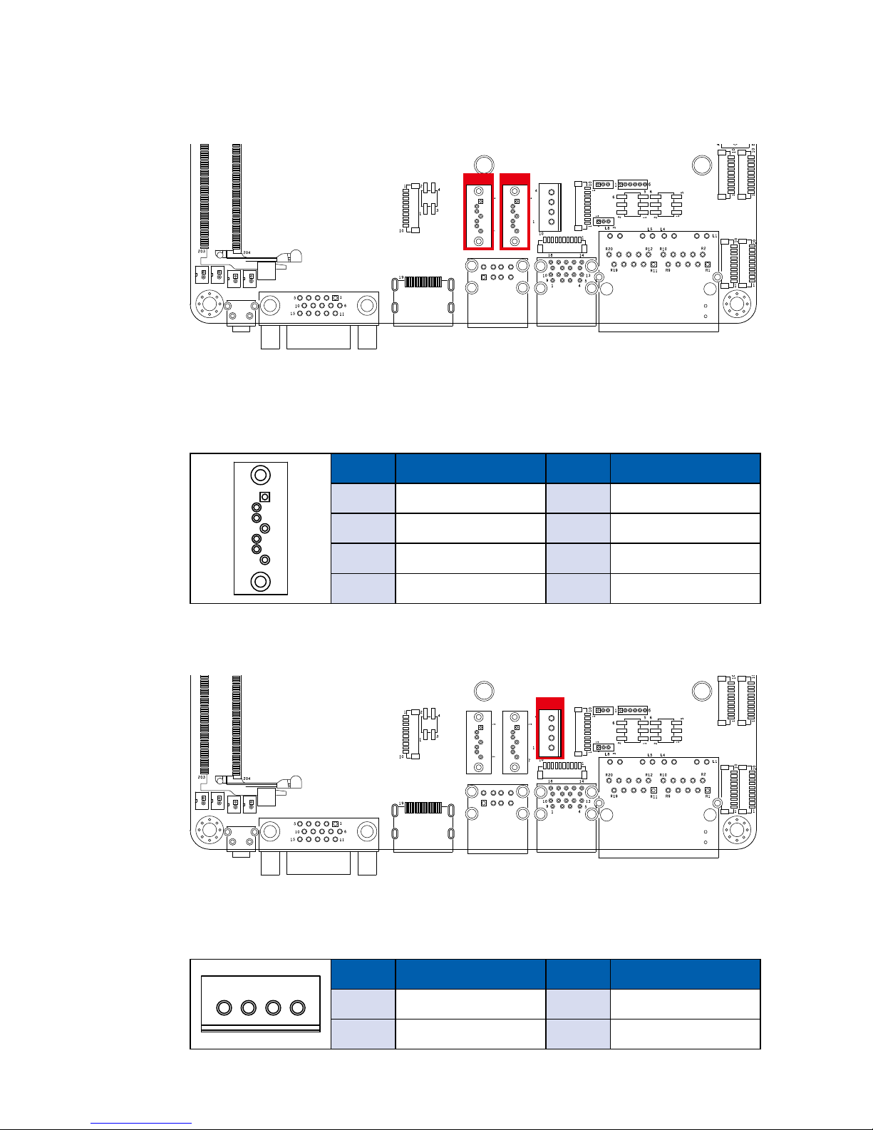
2.2.8 CN6 To CN9 : COM 1 To COM 4 Serial Port
The serial port 1 to 4 can be congured for RS-232, RS-422, or RS-485 with auto
ow control communication. The default denition of COM 1 to COM 4 is RS-232.
If you want to change to RS-422 or RS-485, you can nd the setting in BIOS.
BIOS Setting Function
COM 1 (CN6) (Isolated)
COM 2 (CN7) (Isolated)
COM 3 (CN8)
COM 4 (CN9)
RS-232
RS-422 (5-wire)
RS-422 (9-wire)
RS-485
RS-485 w/z auto-ow control
CN8 CN9
CN6 CN7
Mechanical Key
Pin No. Signal Name Pin No. Signal Name
15 GND 16 UIM_VPP
13 REFCLK+ 14 UIM_RESET
11 REFCLK- 12 UIM_CLK
9 GND 10 UIM_DATA
7 CLKREQ# 8 UIM_PWR
5 Reserved 6 1.5V
3 Reserved 4 GND
1 WAKE# 2 3.3Vaux
Page 21
15
©Vecow EMBC-2000 User Manual
GETTING TO KNOW YOUR EMBC-2000
The pin assignments of CN13 are listed in the following table :
Serial
Port
Pin No. RS-232
RS-422
(5-wire)
RS-422
(9-wire)
RS-485
(3-wire)
1, 2, 3, 4
1 GND_EARTH GND_EARTH GND_EARTH GND_EARTH
2 GND GND GND GND
3 RI ----------- CTS- RI
4 DTR RXD- RXD- -----------
5 CTS ----------- CTS+ -----------
6 TXD RXD+ RXD+ -----------
7 RTS ----------- RTS+ -----------
8 RXD TXD+ TXD+ DATA +
9 DSR ----------- RTS- -----------
10 DCD TXD- TXD- DATA-
101
2.2.9 VGA
Pin No. Signal Name Pin No. Signal Name
1 Red 2 Green
3 Blue 4 N/C
5 GND 6 GND
7 GND 8 GND
9 P5V 10 GND
11 N/C 12 DDC Data
13 Horizontal Sync 14 Vertical Sync
15 DDC Clock
15
610
1115
VGA2
Page 22
16
©Vecow EMBC-2000 User Manual
GETTING TO KNOW YOUR EMBC-2000
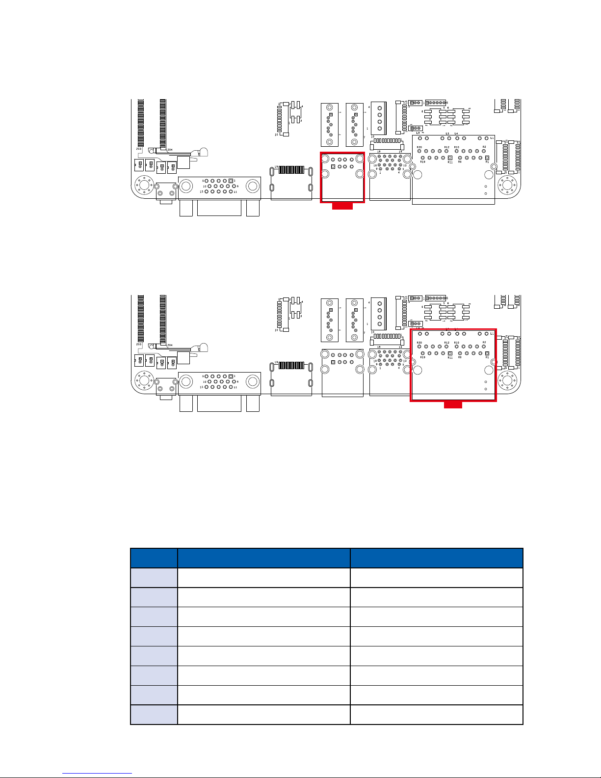
2.2.10 CN12 : External USB
There are 2 USB 2.0 connections available supporting up to 480MB per second
data rate in the top side of EMBC-2000.
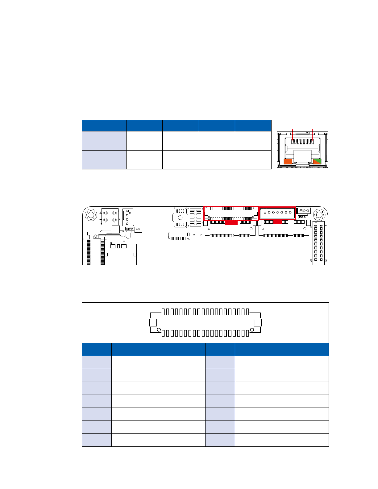
2.2.11 CN5 : LAN
There are 2 8-pin RJ-45 jacks supporting 10/100/1000 Mbps Ethernet
connections. LAN 1 (Right side)/LAN 2 (Left side) are powered by Intel® I210
Ethernet engine. When both LAN 1 and LAN 2 work in normal status, basic
iAMT function is enabled.
Using suitable RJ-45 cable, you can connect EMBC-2000 system to a computer,
or to any other devices with Ethernet connection, for example, a hub or a
switch. Moreover, both of LAN 1 and LAN 2 supports Wake on LAN and Preboot functions. The pinouts of LAN 1 and LAN 2 are listed as follows :
Pin No. 10/100 Mbps 1000Mbps
1 E_TX+ MDI0_P
2 E_TX- MDI0_N
3 E_RX+ MDI1_P
4 ---- MDI2_P
5 ----- MDI2_N
6 E_RX- MDI1_N
7 ----- MDI3_P
8 ------ MDI3_N
CN5
CN12
Page 23
17
©Vecow EMBC-2000 User Manual
GETTING TO KNOW YOUR EMBC-2000
Each LAN port is supported by standard RJ-45 connector with LED indicators to
present Active/Link/Speed status of the connection.
The LED indicator on the right bottom corner lightens in solid green when the
cable is properly connected to a 100Mbps Ethernet network; The LED indicator
on the right bottom corner lightens in solid orange when the cable is properly
connected to a 1000Mbps Ethernet network; The left LED will keep twinkling/off
when Ethernet data packets are being transmitted/received.
LED Location LED Color 10Mbps 100Mbps 1000Mbps
Right
Green/
Orange
Off
Solid
Green
Solid
Orange
Left Yellow
Twinkling
Yellow
Twinkling
Yellow
Twinkling
Yellow
1 8
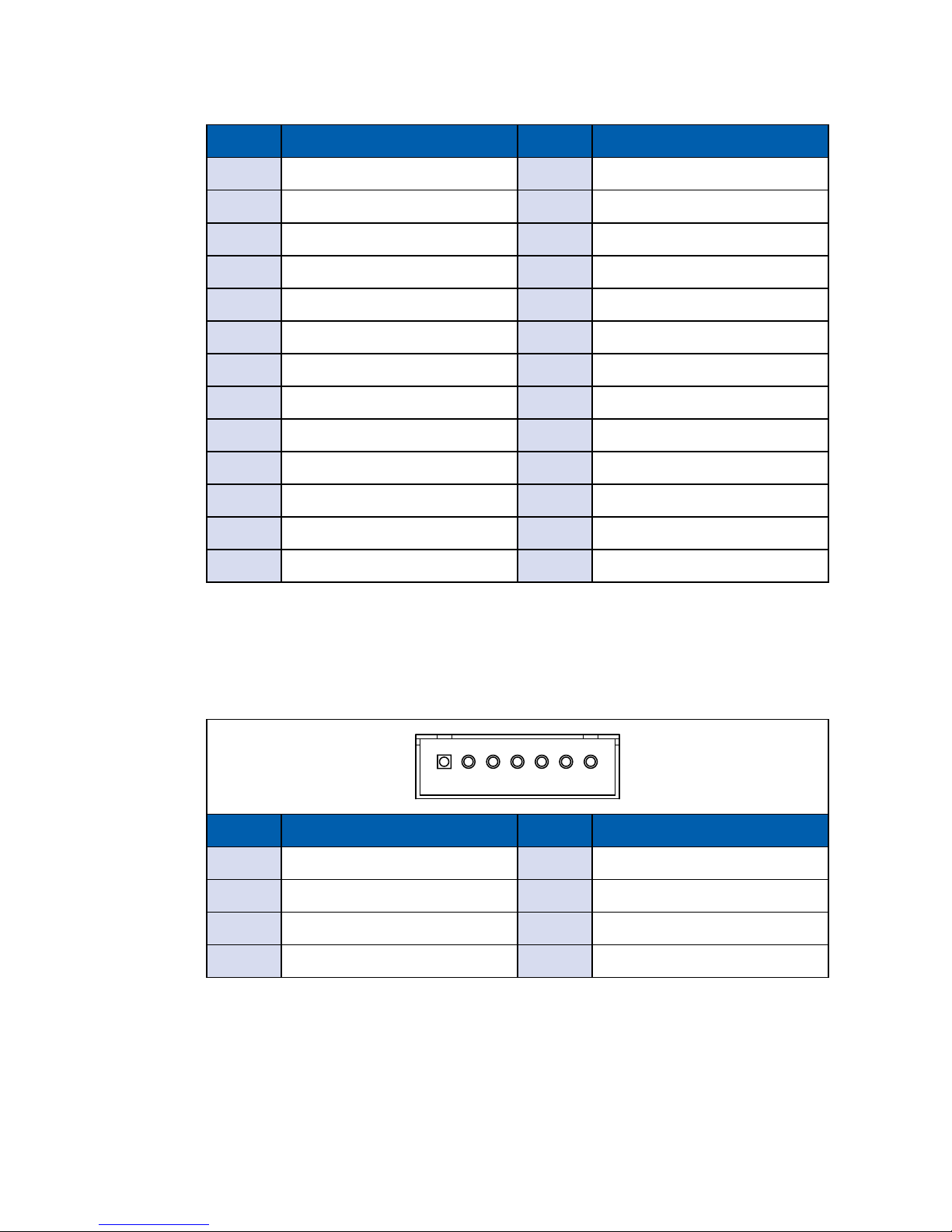
2.2.12 CON1, J4 : LVDS
CON1
EMBC-2000 supports dual-channel 24-bit LVDS display and up to 1920 x 1200
pixels resolution. The pin assignments of CON1 are listed in the following table :
Pin No. Signal Name Pin No. Signal Name
1 PANEL_VDD 2 TXO0-
3 PANEL_VDD 4 TXO0+
5 PANEL_VDD 6 TXO1-
7 GND 8 TXO1+
9 GND 10 TXO2-
11 GND 12 TXO2+
13 GND 14 TXOC-
40 2
39 1
CON1
J4
Page 24
18
©Vecow EMBC-2000 User Manual
GETTING TO KNOW YOUR EMBC-2000
Pin No. Signal Name Pin No. Signal Name
15 GND 16 TXOC+
17 GND 18 TXO3-
19 GND 20 TXO3+
21 GND 22 TXE0-
23 GND 24 TXE0+
25 GND 26 TXE1-
27 GND 28 TXE1+
29 GND 30 TXE2-
31 GND 32 TXE2+
33 GND 34 TXEC-
35 GND 36 TXEC+
37 GND 38 TXE3-
39 LVDS_DET# 40 TXE3+
J4
The LCD inverter is connected to J4 via a JST 7-pin, 2.5mm connector providing
+5V/+12V power to LCD display. The pin assignments are listed in the following
table :
Pin No. Signal Name Pin No. Signal Name
1 +5V 2 +12V
3 +12V 4 LBKLT_CTL
5 GND 6 GND
7 LBKLT_EN
1 7
Page 25
19
©Vecow EMBC-2000 User Manual
GETTING TO KNOW YOUR EMBC-2000
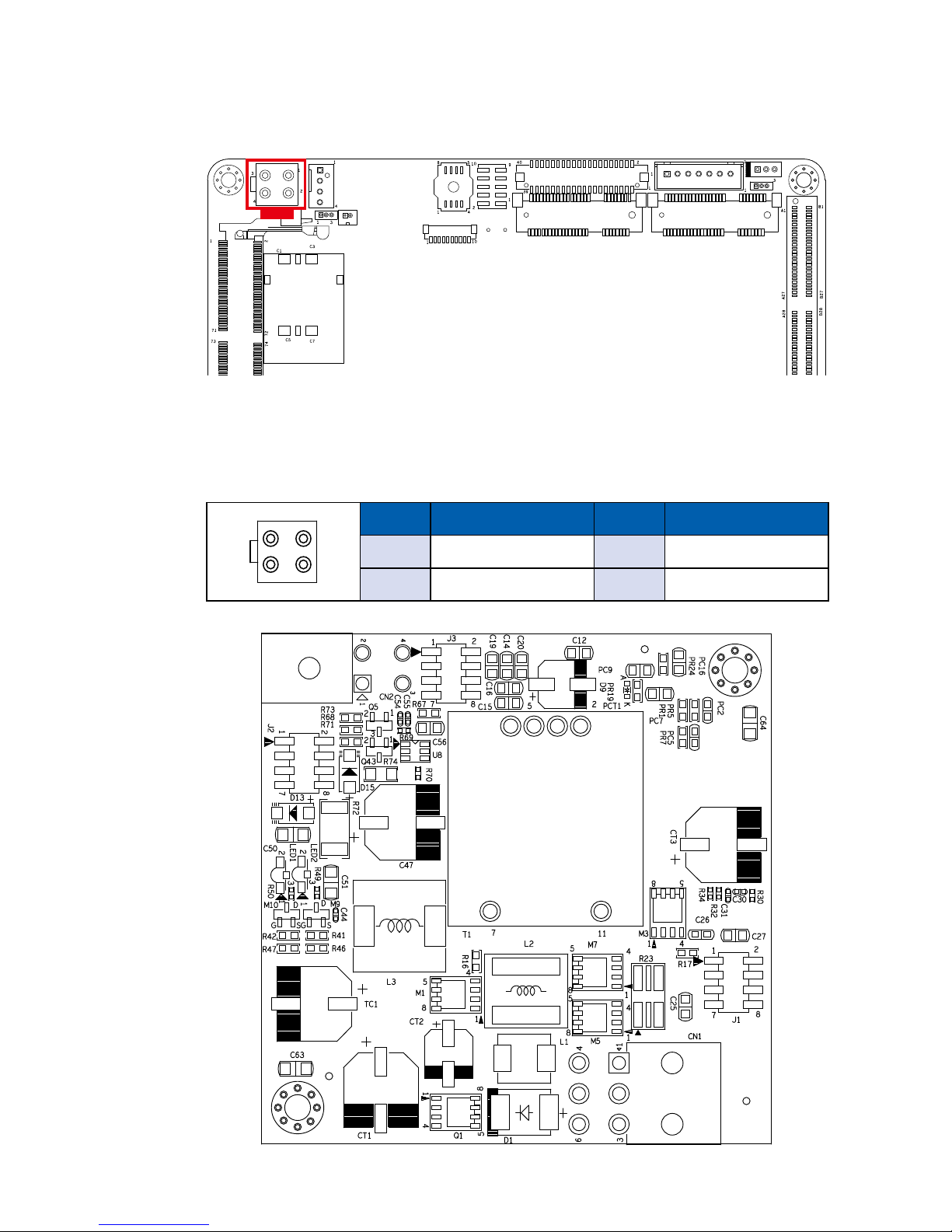
2.2.13 CN18 : Power Input
EMBC-2000 supports 12V DC power input by wire-to-board connector on the
top side. It can optionally support 9V to 36V input through an additional widerange voltage power board, WPM-101. (please nd below image and WPM-101
can be selected on the ordering information).
Pin No. Denition Pin No. Denition
1 GND 2 GND
3 +12V 4 +12V
CN18
1
2
3
4
Page 26
20
©Vecow EMBC-2000 User Manual
GETTING TO KNOW YOUR EMBC-2000
2.2.14 CN1, CN2 : SATA III Connector
There are 2 onboard high performance Serial ATA III (SATA III) on EMBC-2000.
It supports higher storage capacity with less cabling effort and smaller required
space. CN1 is co-use with CN15,which is selected by jumper JP5. The pin
assignments of CN1 and CN2 are listed in the following table :
Pin No. Signal Name Pin No. Signal Name
1 GND 2 TXP
3 TXN 4 GND
5 RXN 6 RXP
7 GND
1
7
2.2.15 J1 : SATA Power Connector
EMBC-2000 is also equipped with one SATA power connector. It supports
5V (Up to 2A) and 12V (Up to 1A) current to the hard drive or SSD. The pin
assignments of J1 is listed in the following table :
Pin No. Signal Name Pin No. Signal Name
1 +12V 2 GND
3 GND 4 +5V
1 4
J1
CN1 CN2
Page 27
21
©Vecow EMBC-2000 User Manual
GETTING TO KNOW YOUR EMBC-2000
2.2.16 CN16 : Riser PCIe Slot
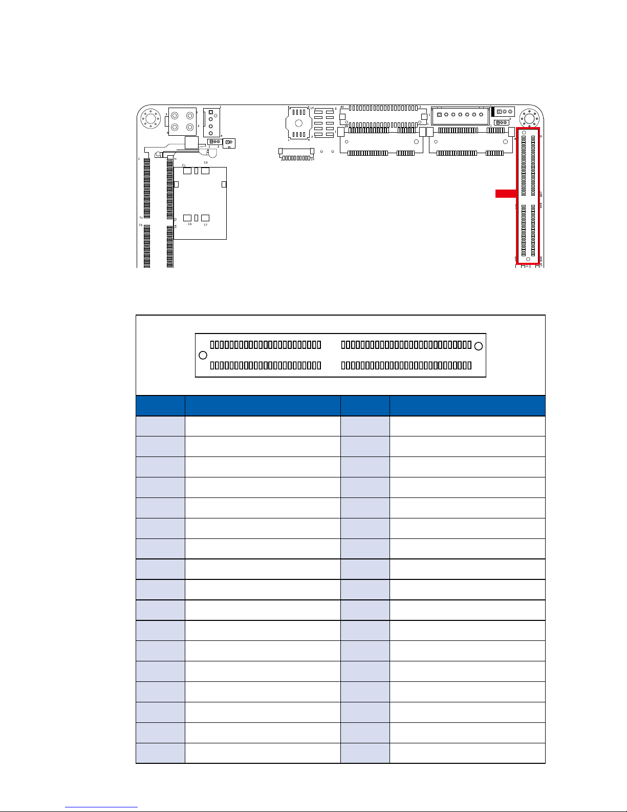
CN16 is used to connect with the riser card. The pin assignments of CN16 is
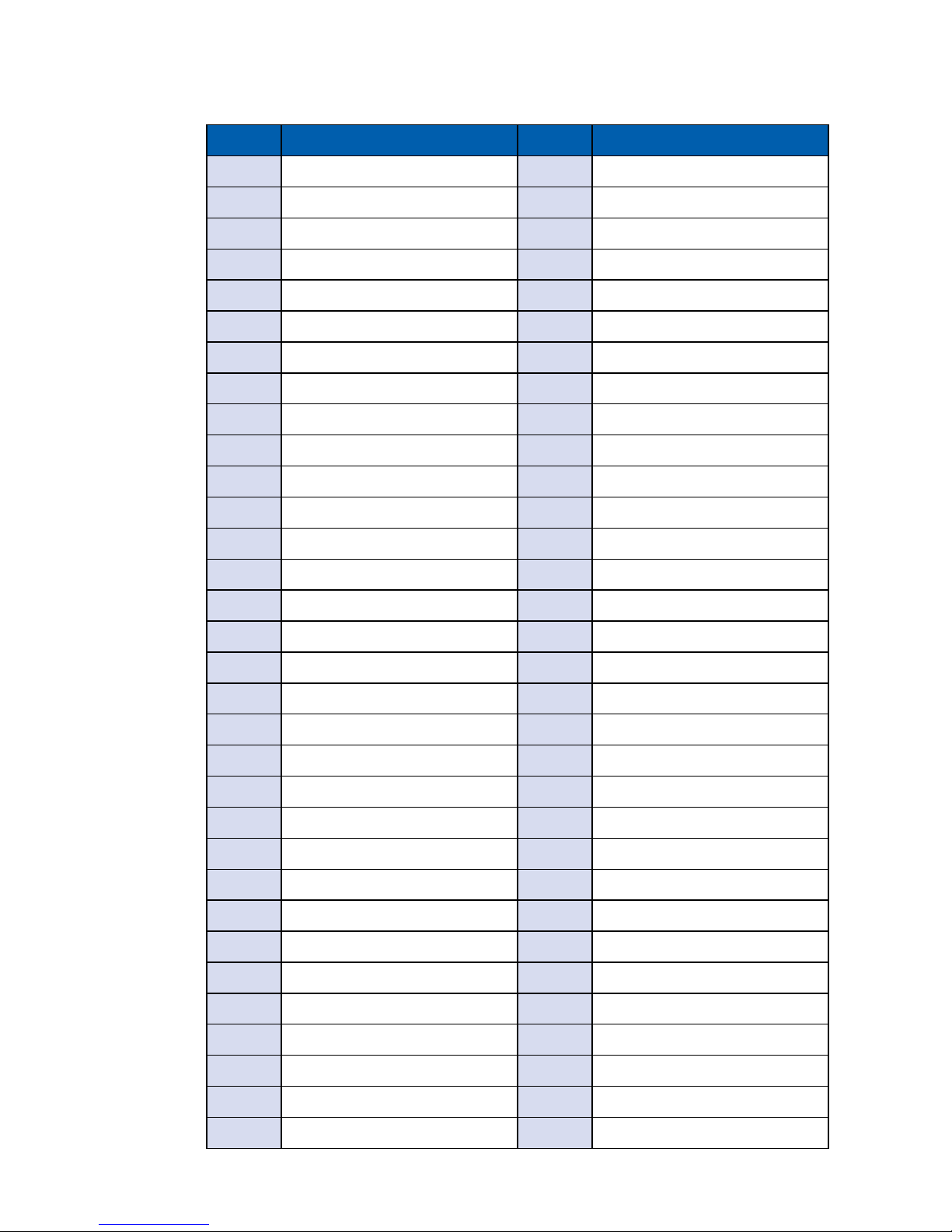
listed in the following table :
Pin No. Signal Name Pin No. Signal Name
A1 P3V3 B1 P3V3
A2 P3V3 B2 P3V3
A3 P3V3 B3 P3V3
A4 N/C B4 N/C
A5 GND B5 S_SMB_CLK
A6 GND B6 S_SMB_DAT
A7 GND B7 GND
A8 +12V_EN_R B8 GND
A9 GND B9 N/C
A10 GND B10 P3V3_A
A11 BUF_PLTRST_N_A B 11 PCIE_WAKE
A12 GND B12 GND
A13 CLK_PCIe GF1_DP B13 GND
A14 CLK_PCIe GF1_DN B14 PCIE_TXP4
A15 GND B15 PCIE_TXN4
A16 PCIE_RXP4 B16 GND
A17 PCIE_RXN4 B17 GND
A1A27A28A50
B1B27B28B50
CN 16
Page 28
22
©Vecow EMBC-2000 User Manual
GETTING TO KNOW YOUR EMBC-2000
Pin No. Signal Name Pin No. Signal Name
A18 GND B18 GND
A19 GND B19 PCIE_TXP5
A20 GND B20 PCIE_TXN5
A21 PCIE_RXP5 B21 GND
A22 PCIE_RXN5 B22 GND
A23 GND B23 GND
A24 GND B24 GND
A25 CLK_PCIe GF2_DP B25 GND
A26 CLK_PCIe GF2_DN B26 GND
A27 GND B27 GND
A28 GND B28 GND
A29 GND B29 GND
A30 N/C B30 N/C
A31 P3V3 B31 P5V
A32 P3V3 B32 P5V
A33 P3V3 B33 P5V
A34 P3V3 B34 P5V
A35 P3V3 B35 P5V
A36 P3V3 B36 P5V
A37 N/C B37 N/C
A38 GND B38 GND
A39 GND B39 GND
A40 USB_D_7P B40 USB_D_6P
A41 USB_D_7N B41 USB_D_6N
A42 GND B42 GND
A43 GND B43 GND
A44 GND B44 GND
A45 GND B45 N/C
A46 N/C B46 P12V
A47 P12V B47 P12V
A48 P12V B48 P12V
A49 P12V B49 P12V
Page 29
23
©Vecow EMBC-2000 User Manual
GETTING TO KNOW YOUR EMBC-2000
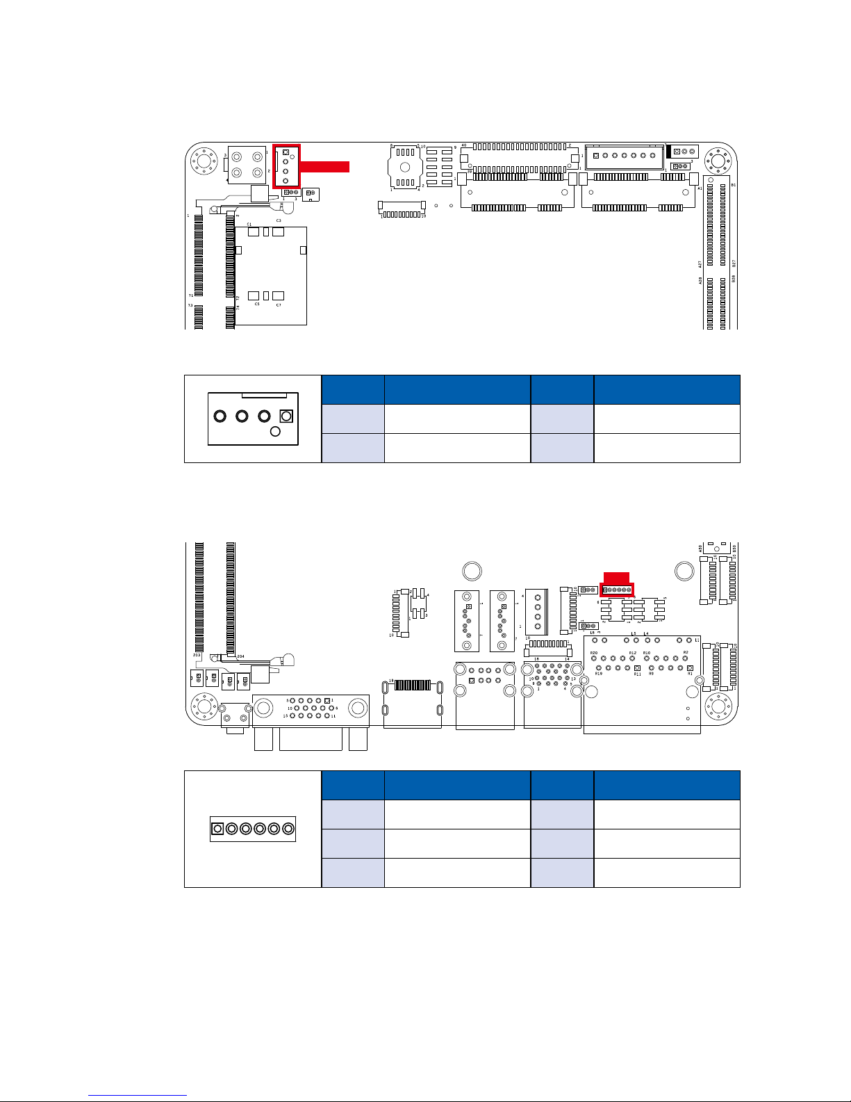
2.2.17 FAN1 : FAN Power Connector
2.2.18 JPS2 : PS/2 Mouse Keyboard Pin Head
Pin No. Signal Name Pin No. Signal Name
1 SIO_MCLK 2 SIO_MDAT
3 GND 4 SIO_KCLK
5 SIO_KDAT 6 VCC5_KBMS
1 6
JPS2
FAN power connector supports for higher thermal requirement.
Pin No. Signal Name Pin No. Signal Name
1 GND 2 +12V
3 FAN_TAC 4 FAN_CTL
14
CPU_FAN1
Page 30
24
©Vecow EMBC-2000 User Manual
GETTING TO KNOW YOUR EMBC-2000
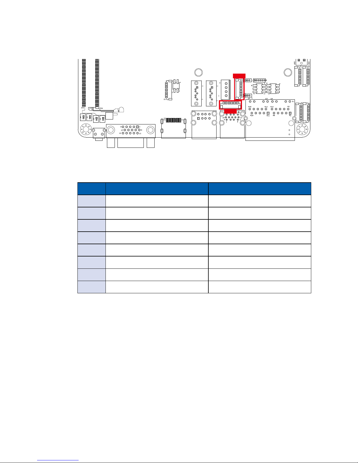
2.2.19 JDIO1, JDIO2 : GPIO
There is a 16-bit GPIO connector on the top side. Each GPIO channel can be
conguration GPI or GPO. Please refer to below table to see the pin denition in
details. JDIO1 and JDIO2 Pin dene are as below.
Pin No. JDIO1 Denition JDIO2 Denition
1 SIO_GPI80 SIO_GPI84
2 SIO_GPI81 SIO_GPI85
3 SIO_GPI82 SIO_GPI86
4 SIO_GPI83 SIO_GPI87
5 SIO_GPO70 SIO_GPO74
6 SIO_GPO71 SIO_GPO75
7 SIO_GPO72 SIO_GPO76
8 SIO_GPO73 SIO_GPO77
JDIO2
JDIO1
Page 31
25
©Vecow EMBC-2000 User Manual
GETTING TO KNOW YOUR EMBC-2000
2.2.20 Bottom Side
LED2
SW3
LED1
2.2.21 PWR and HDD LED Indicator
LED2 LED1
Power LED (LED1) : If the LED is solid green, it indicates that the system is
powered on.
HDD LED (LED2) : If the LED is on, it indicates that the system’s storage is
functional. If it is off, it indicates that the system’s storage is not functional. If it is
ashing, it indicates data access activities.
LED Color Indication System Status
Orange HDD
On/Off : Storage status, function or not.
Twinkling: Data transferring.
Green Power System power status (On/Off)
Page 32
26
©Vecow EMBC-2000 User Manual
GETTING TO KNOW YOUR EMBC-2000
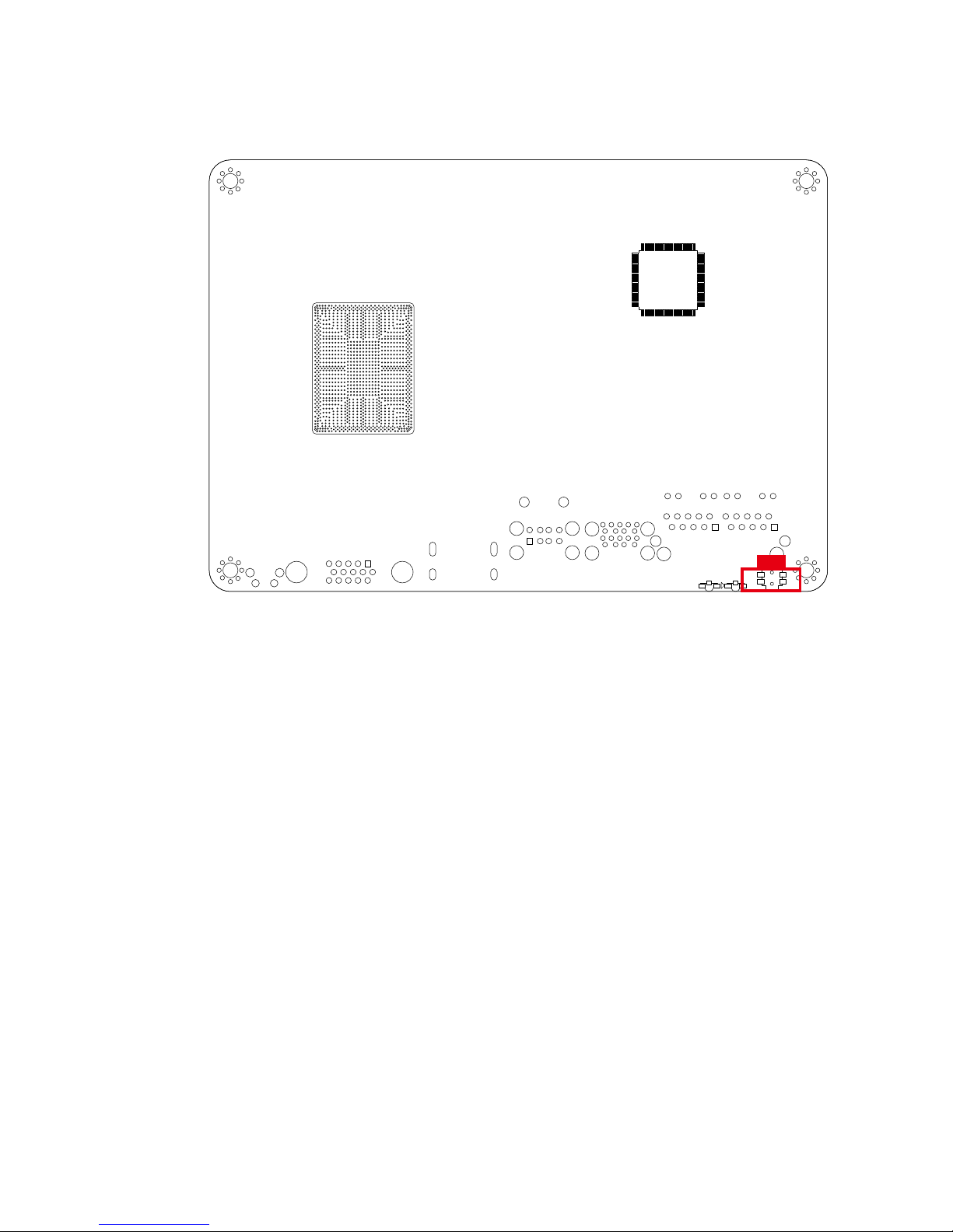
2.2.22 Reset Tact Switch
SW3
It is a hardware reset switch. Use this switch to reset the system without power
off the system. Press the Reset Switch for a few seconds, and then reset will be
enabled.
Page 33
27
©Vecow EMBC-2000 User Manual
GETTING TO KNOW YOUR EMBC-2000
2.3 Main Board Jumper Settings
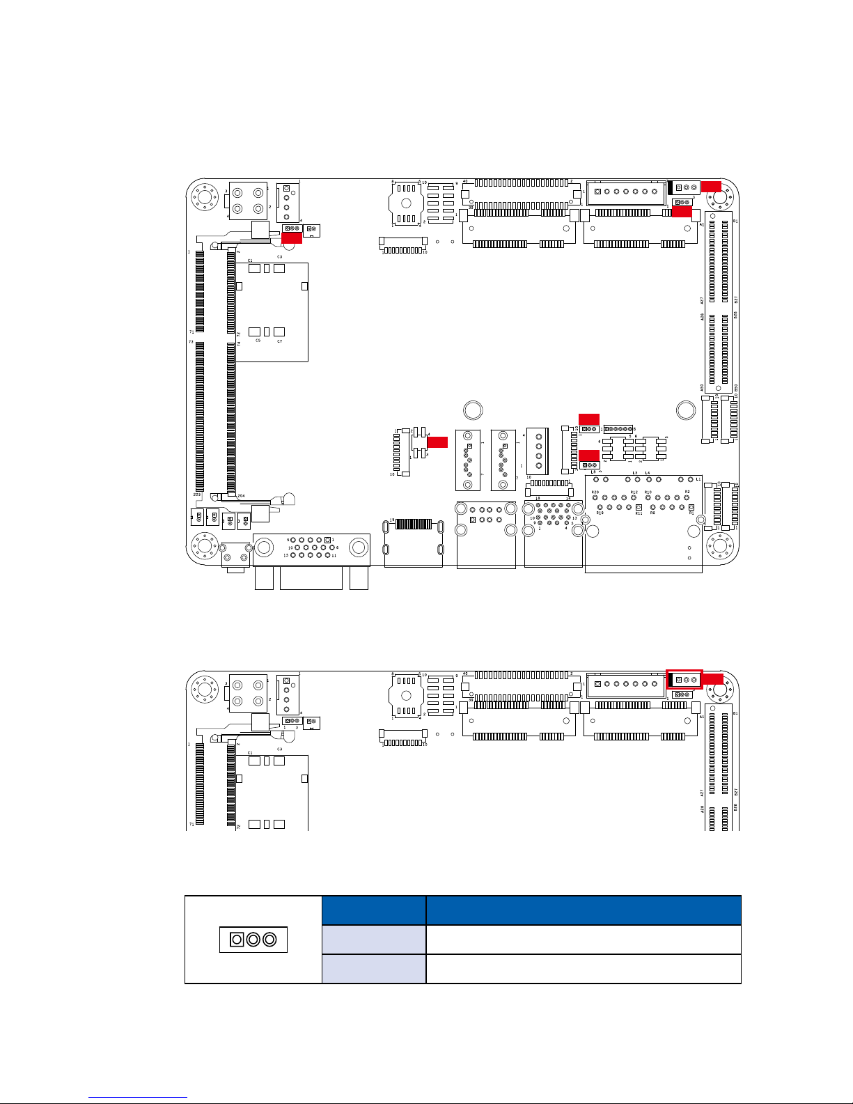
2.3.1 Front View of EMBC-2000 Main Board With Jumper Location
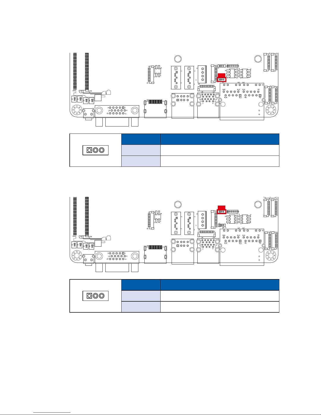
JP6
JP2
JP3
JP5
JP4
JP7
2.3.2 JP3 : LVDS Module, Power Selection
JP3
JP3 provides LVDS voltage selection function, closing Pin 1, 2 is for 3.3V LVDS
power input; closing Pin 2, 3 is for 5V LVDS power input.
Pin No. Function
1-2 +3.3V (Default)
2-3 +5V
1 3
Page 34
28
©Vecow EMBC-2000 User Manual
GETTING TO KNOW YOUR EMBC-2000
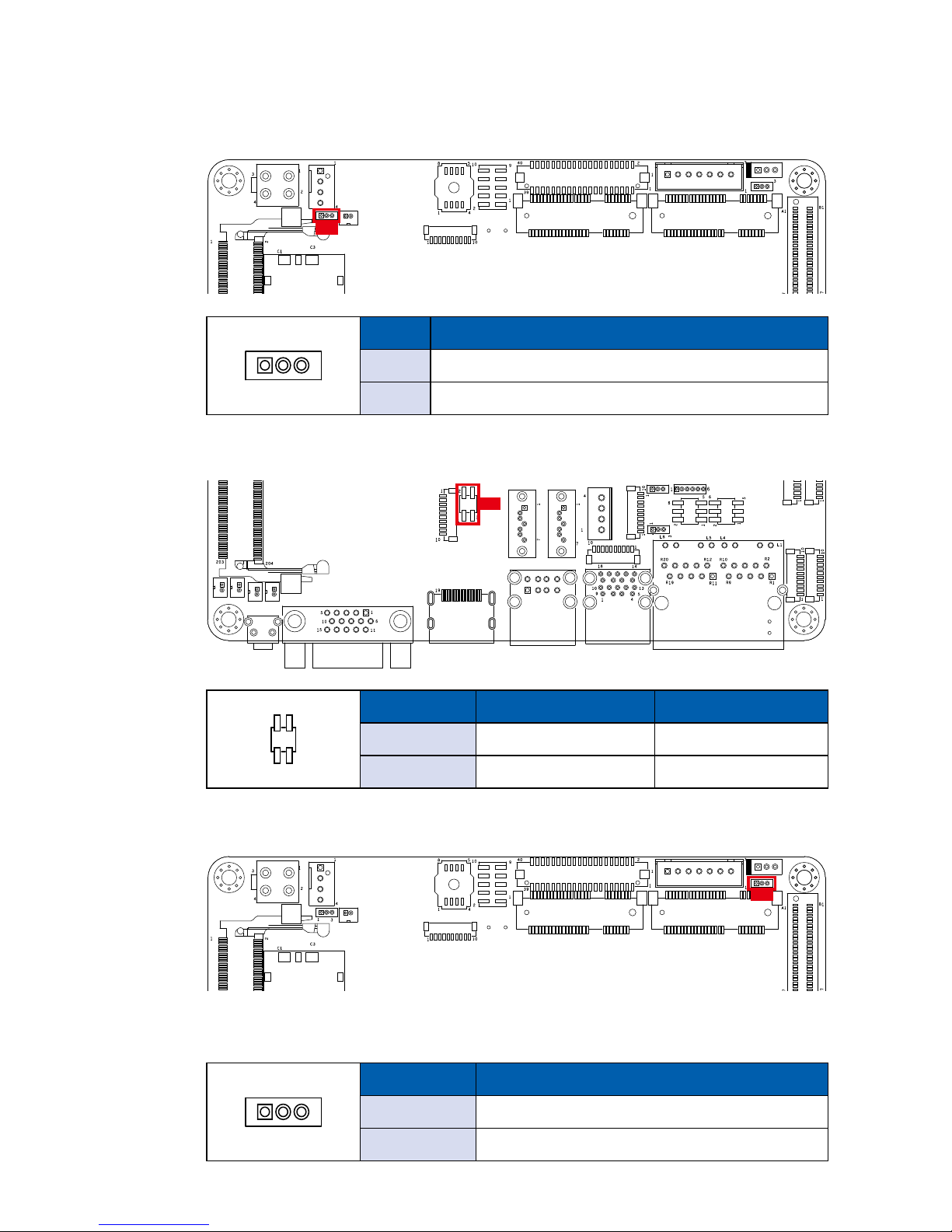
2.3.3 JP6 : CMOS
JP6
Pin No. Function
1-2 Normal (Default)
2-3 Clear CMOS
1 3
2.3.4 JP5
:
CN13 mSATA/Mini PCIe; CN1 SATA/NC select
JP5
Pin No. CN15 CN1
1-3/2-4 m SATA N/C
N/C Mini PCIe (Default) SATA
2 4
1 3
2.3.5 JP2 : Backlight Control Level Select
JP2
JP2 provides LVDS backlight control selection function, closing Pin 1, 2 is for 3.3V
and closing Pin 2, 3 is for 5V
Pin No. Function
1-2 +3.3V (Default)
2-3 +5V
1 3
Page 35
29
©Vecow EMBC-2000 User Manual
GETTING TO KNOW YOUR EMBC-2000
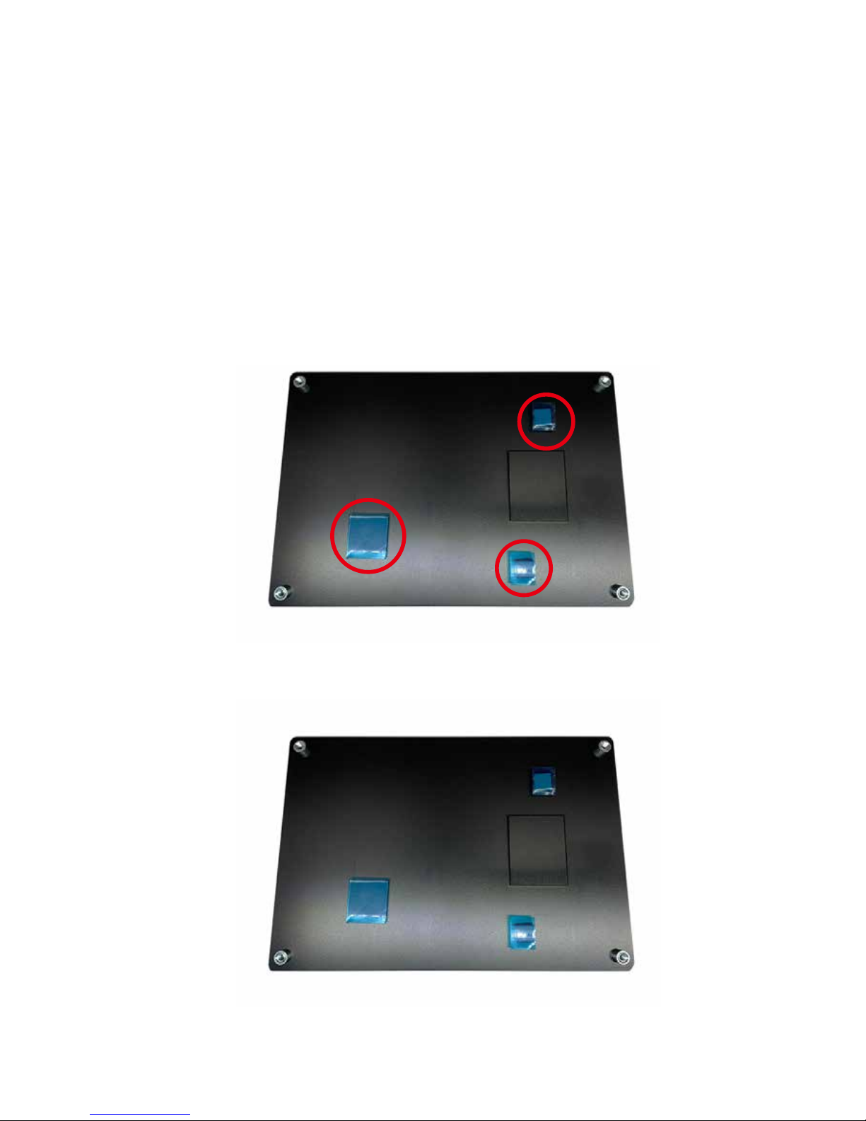
2.3.6 JP4 : USB Power Select
JP4
Pin No. Function
1-2 +5V Standby Power (Default)
2-3 +5V System Power
1 3
2.3.7 JP7 : GPI Signal Pull High Power Rail Select
JP7
Pin No. SIO_GPI80 to SIO_GPI87
1-2 Pull high to P3V3_A (Default)
2-3 Hi-Z
1 3
Page 36
30
©Vecow EMBC-2000 User Manual
SETUP
3
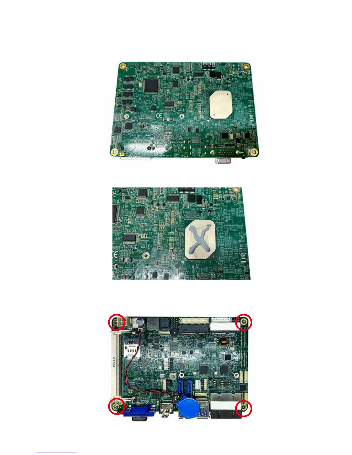
Step 2 Finished.
SETUP
3.1 Installing Heat Spreader
Step 1 Remove lms on the thermal pads.
Page 37
31
©Vecow EMBC-2000 User Manual
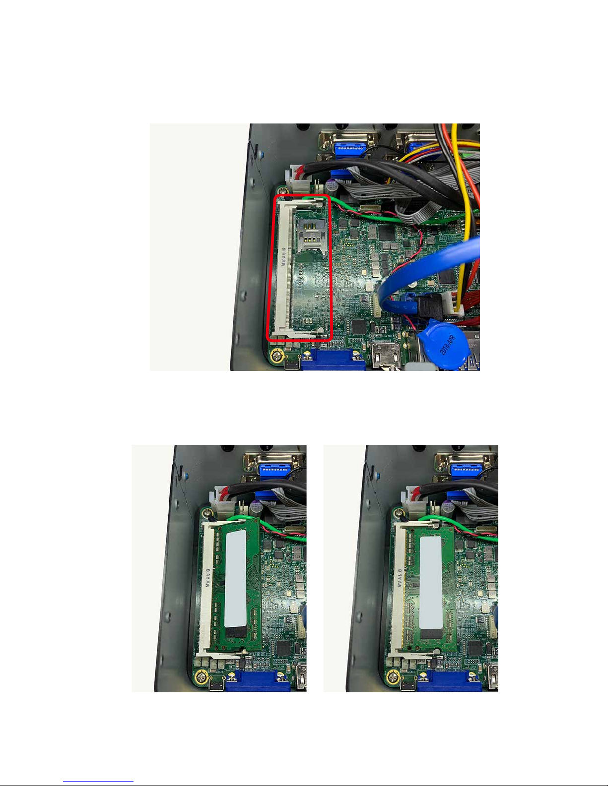
SETUP
Step 3 Look at EMBC-2000 CPU.
Step 4 Paint the thermal grease on the CPU like ‘X’ shape.
Step 5 Fasten four PHILLIPS M3*4L screws.
Page 38
32
©Vecow EMBC-2000 User Manual
SETUP
3.2 Installing DDR3L Module
Step 1 Find DDR3L SO-DIMM socket. (Note: only Non-ECC supported)
Step 2 Install DDR3L RAM module
into SO-DIMM socket.
Step 3 Finished.
Page 39
33
©Vecow EMBC-2000 User Manual
SETUP
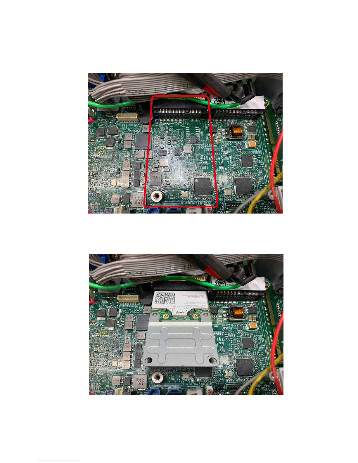
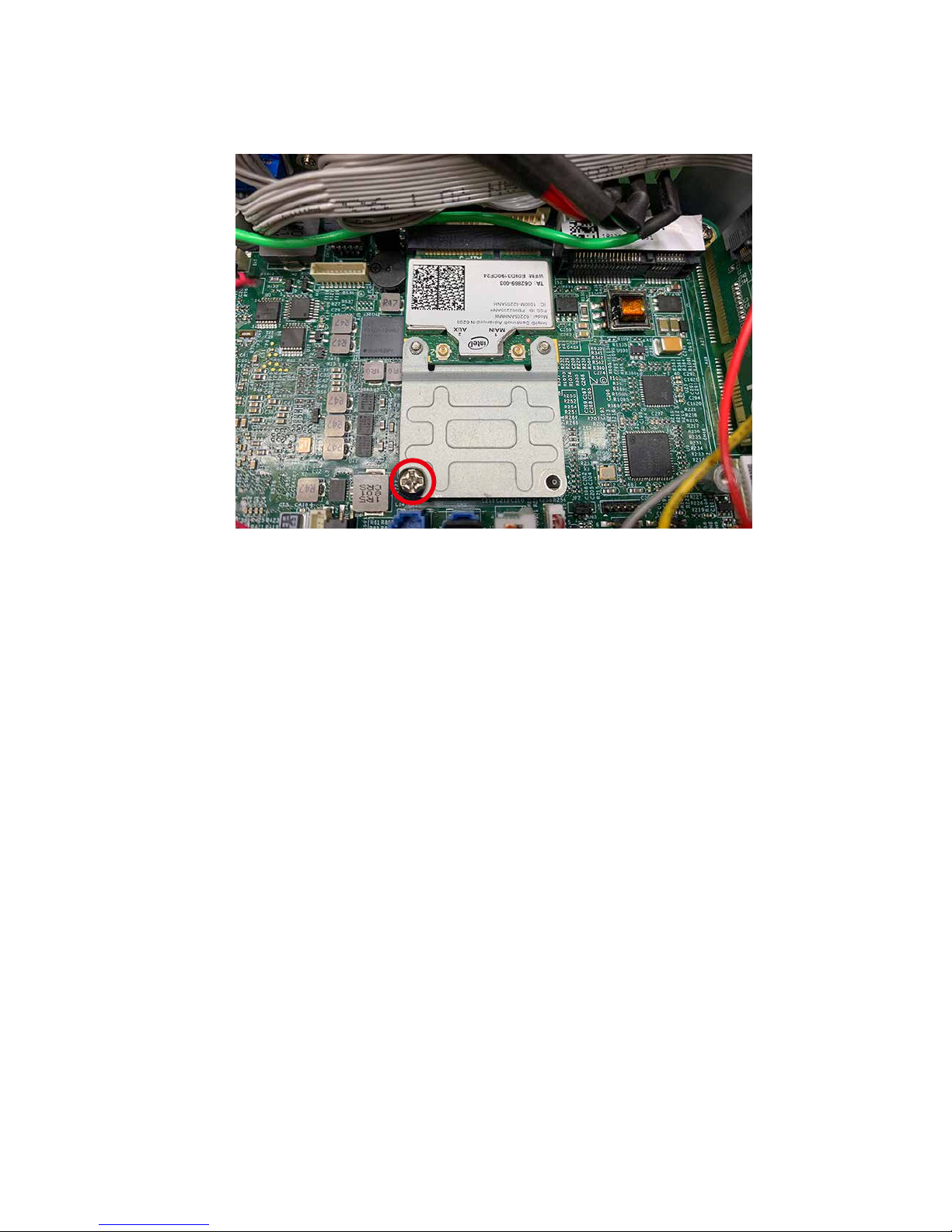
3.3 Installing Mini PCIe Card
Step 1 Find Mini PCIe socket.
Step 2 Install Mini PCIe card into socket.
Page 40
34
©Vecow EMBC-2000 User Manual
SETUP
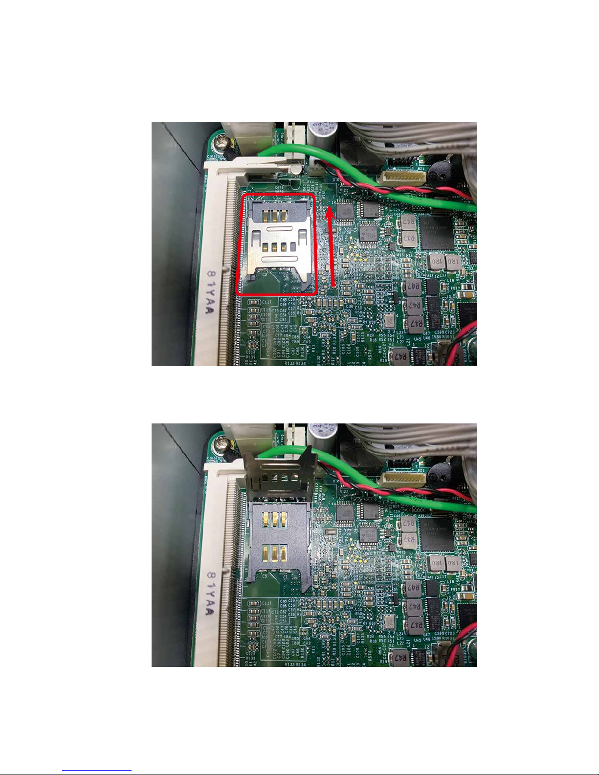
Step 3 Fasten a PHILLIPS M2.5 screw.
Page 41
35
©Vecow EMBC-2000 User Manual
SETUP
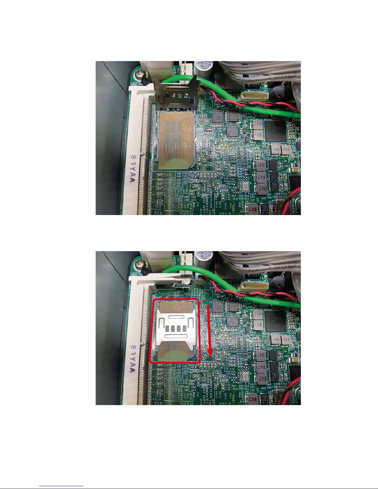
Step 2 Open situation.
3.4 Installing SIM Card
Step 1 Push SIM card slot cover to open.
Page 42
36
©Vecow EMBC-2000 User Manual
SETUP
Step 3 Install SIM card and close the cover.
Step 4 Finished.
Page 43
37
©Vecow EMBC-2000 User Manual
BIOS SETUP
BIOS SETUP
4.1 Entering Setup
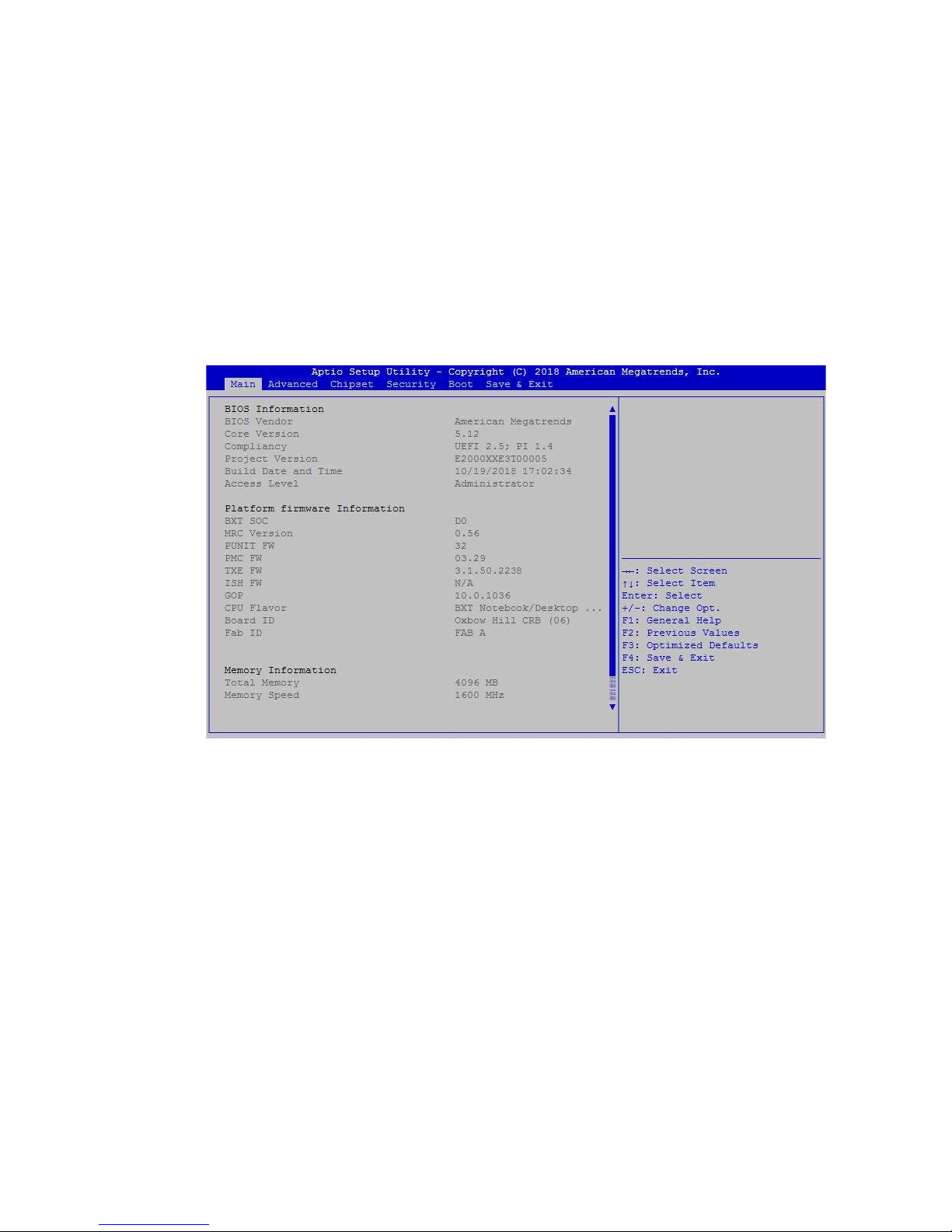
BIOS provides an interface for users to check and change system conguration.
The BIOS setup program is accessed by pressing the <Del> key when POST
display output is shown.
Figure 4-1 : Entering Setup Screen
4
Page 44
38
©Vecow EMBC-2000 User Manual
BIOS SETUP
4.2 Main Menu
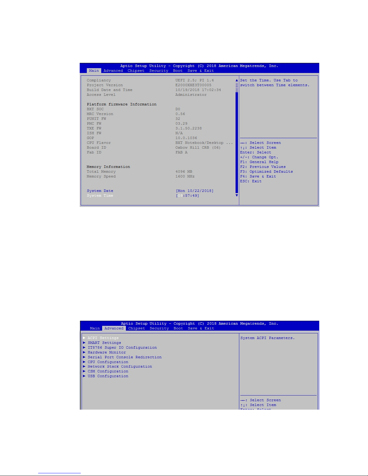
The Main menu displays BIOS version and system information. There are two
options on Main menu.
System Data
Set the date. Use <Tab> to switch between date elements.
System Time
Set the time. Use <Tab> to switch between time elements.
4.3 Advanced
Figure 4-2 : BIOS Main Menu
Figure 4-3 : BIOS Advanced menu
Select advanced tab to enter advanced BIOS setup options, such as CPU
conguration, Network conguration, and USB conguration.
Page 45
39
©Vecow EMBC-2000 User Manual
BIOS SETUP
4.3.1 ACPI Settings
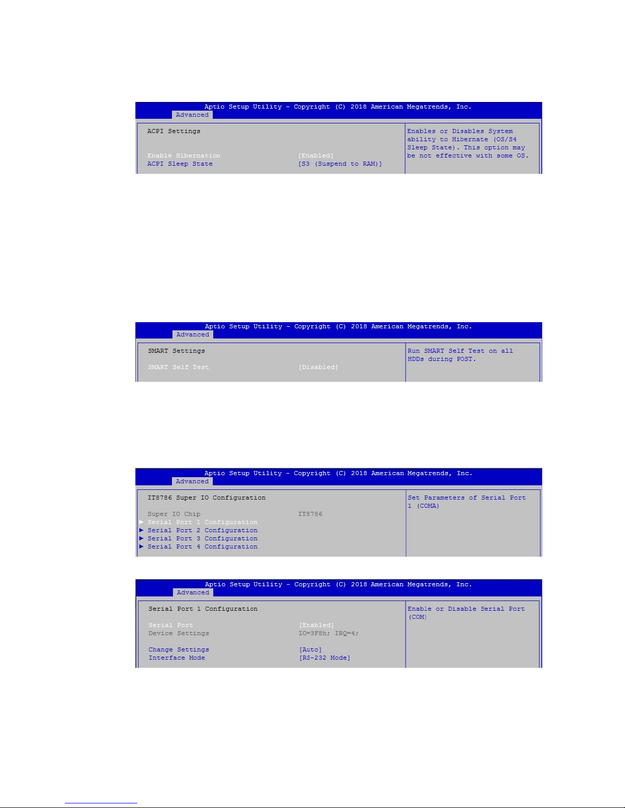
Figure 4-3-1 : ACPI Settings
Enable Hibernation
Enables or Disables System ability to Hibernate (OS/S4 Sleep State). This
option may be not effective with some OS.
ACPI Sleep State
Select the highest ACPI sleep state the system will enter when the SUSPEND
button is pressed.
4.3.2 SMART Settings
Figure 4-3-2 : SMART Settings
SMART Self Test
Run SMART Self Test on all HDDs during POST.
4.3.3 IT8786 Super IO Conguration
Serial Port 1 to Port 4 Conguration
Options for Serial Port 1 to Serial Port 4.
Entering the corresponding Port option then end user can change the settings
such as I/O resource and UART mode.
Figure 4-3-3-1 : Super IO Settings
Figure 4-3-3-2 : Super IO Serial Port Conguration
Page 46
40
©Vecow EMBC-2000 User Manual
BIOS SETUP
4.3.4 Hardware Monitor
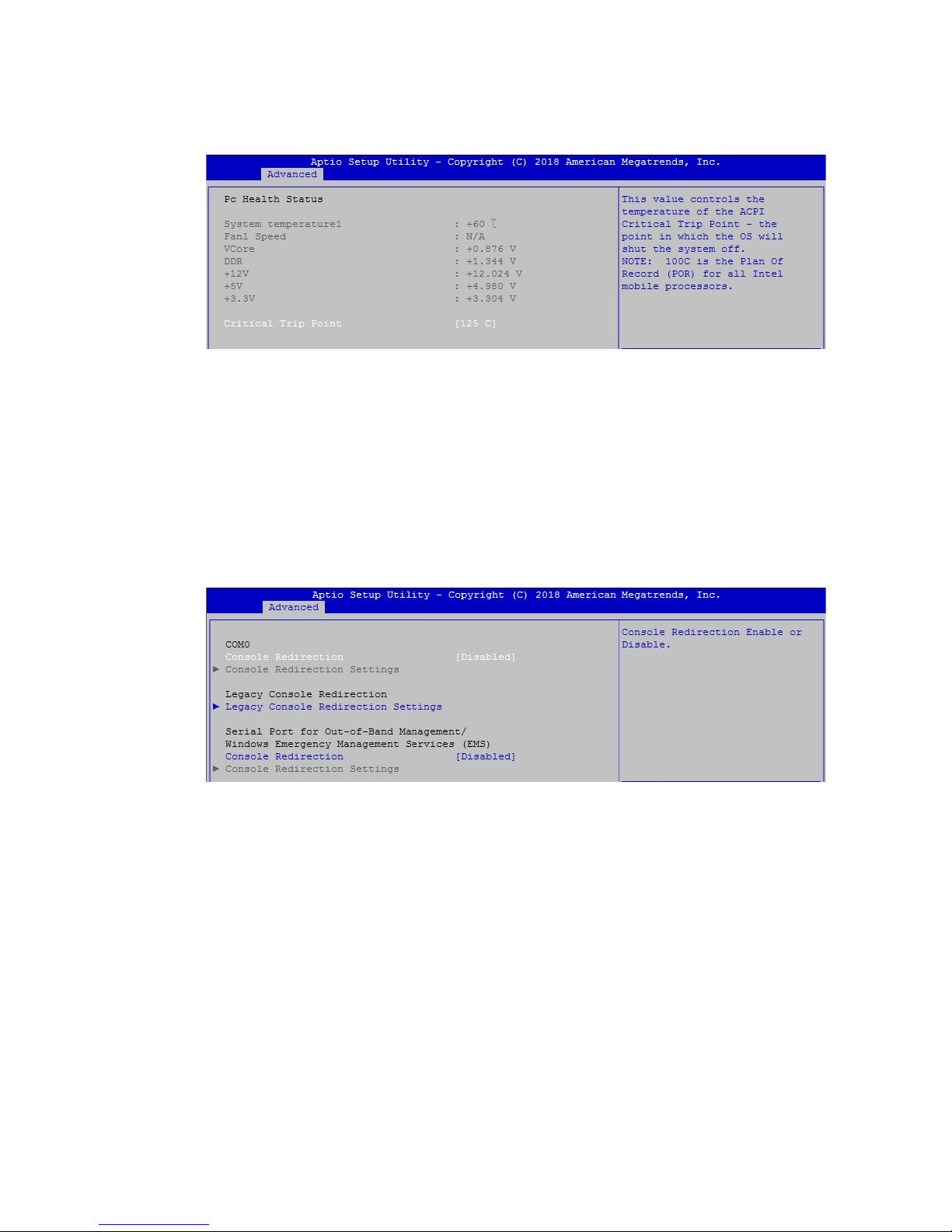
The IT8786 SIO features an enhanced hardware monitor providing thermal, fan
speed, and system voltage's status monitoring.
Critical Trip Point
This value controls the temperature of the ACPI Critical Trip Point - the point in
which the OS will shut the system off.
Figure 4-3-4 : Hardware Monitor Settings
4.3.5 Serial Port Console Redirection
Console Redirection
Console Redirection Enable or Disable.
Console Redirection Settings
The settings specify how the host computer and the remote computer (which
the user is using) will exchange data. Both computers should have the same or
compatible settings.
Legacy Console Redirection
Legacy Console Redirection Settings.
Serial Port for Out-of-Band Management/Windows Emergency Management
Services (EMS)
Console redirection enable or disable.
Figure 4-3-5 : Serial Port Console Redirection Settings
Page 47
41
©Vecow EMBC-2000 User Manual
BIOS SETUP
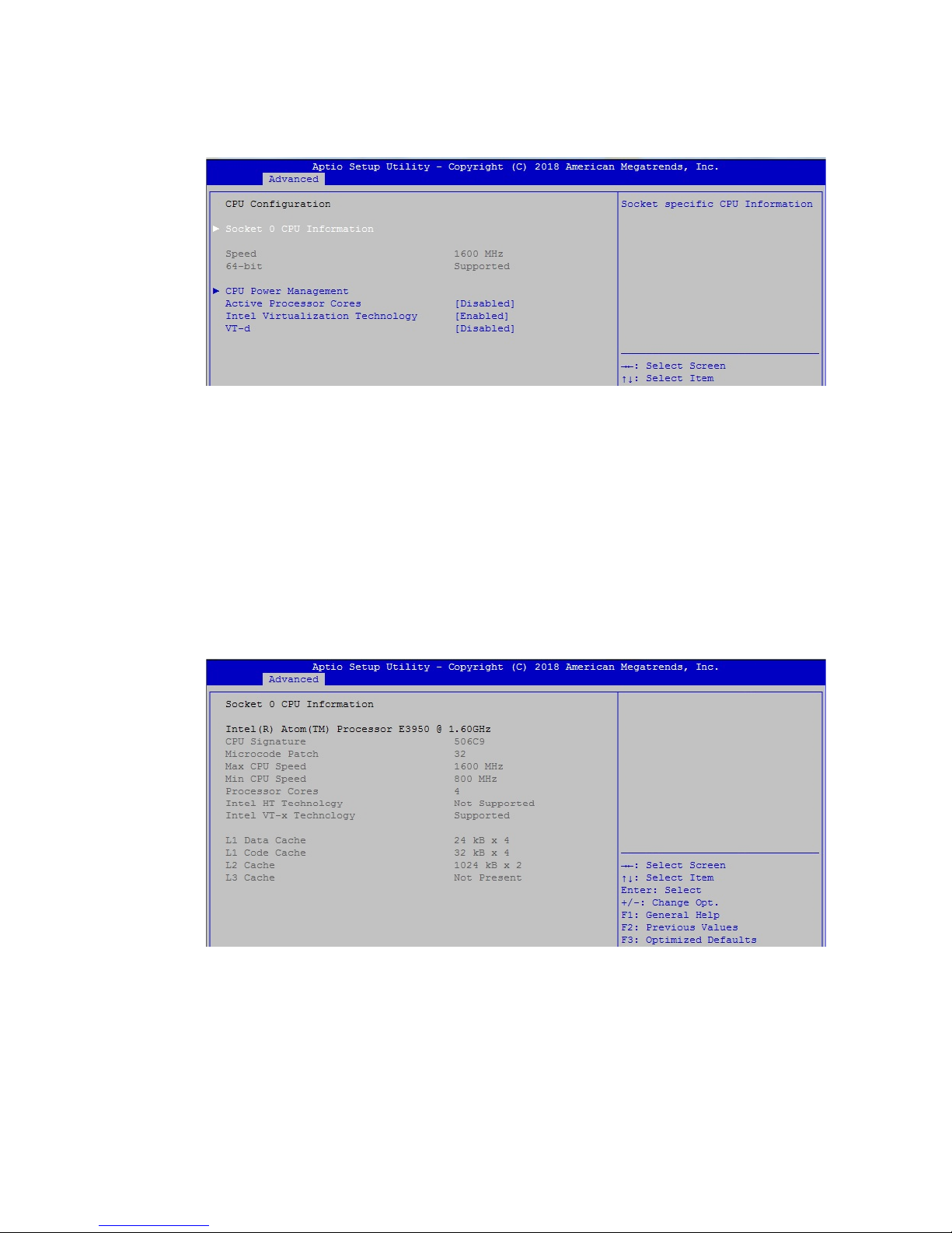
4.3.6 CPU Conguration
Figure 4-3-6-1 : CPU Conguration
Active Processor Cores
Enable this to disable core in each processor package.
Intel Virtualization Technology
When enabled, a VMM can utilize the additional hardware capabilities provided
by Vanderpool Technology.
VT-d
Enable/Disable CPU VT-d.
Figure 4-3-6-2 : CPU Information
Socket Specic CPU Information.
Page 48
42
©Vecow EMBC-2000 User Manual
BIOS SETUP
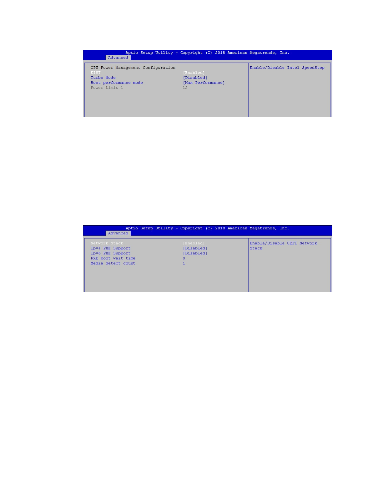
EIST
Enable/Disable Intel SpeedStep.
Turbo Mode
Turbo Mode.
Boot performance mode
Select the performance state that the BIOS will set before OS handoff.
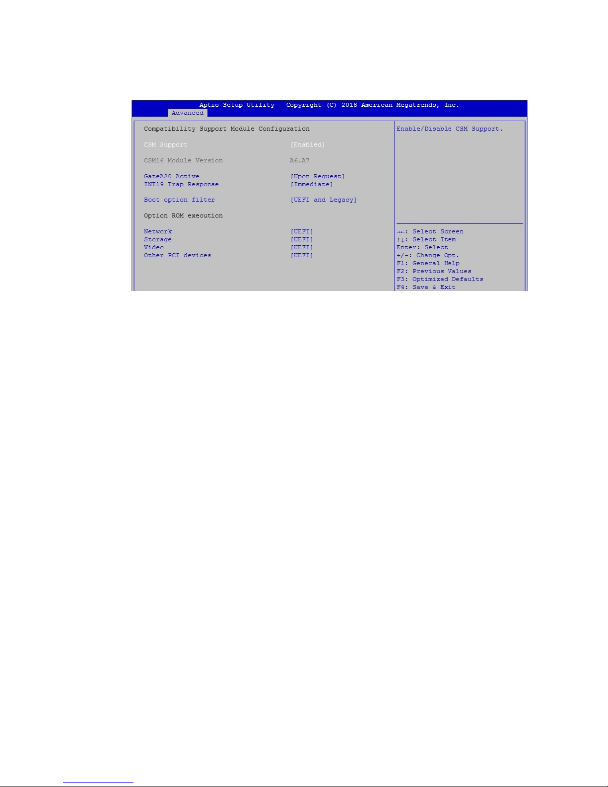
4.3.7 Network Stack Conguration
Figure 4-3-6-3 : CPU Power Management
Network Stack
Enable/Disable UEFI Network Stack.
Ipv4 PXE Support
Enable Ipv4 PXE Boot Support. If disabled IPV4 PXE boot option will not be
created.
Ipv6 PXE Support
Enable Ipv6 PXE boot Support. If disabled IPV6 PXE boot option will not be
created.
PXE boot wait time
Wait time to press ESC key to abort the PXE boot.
Media detect count
Number of times presence of media will be checked.
Figure 4-3-7 : Network Stack Settings
Page 49
43
©Vecow EMBC-2000 User Manual
BIOS SETUP
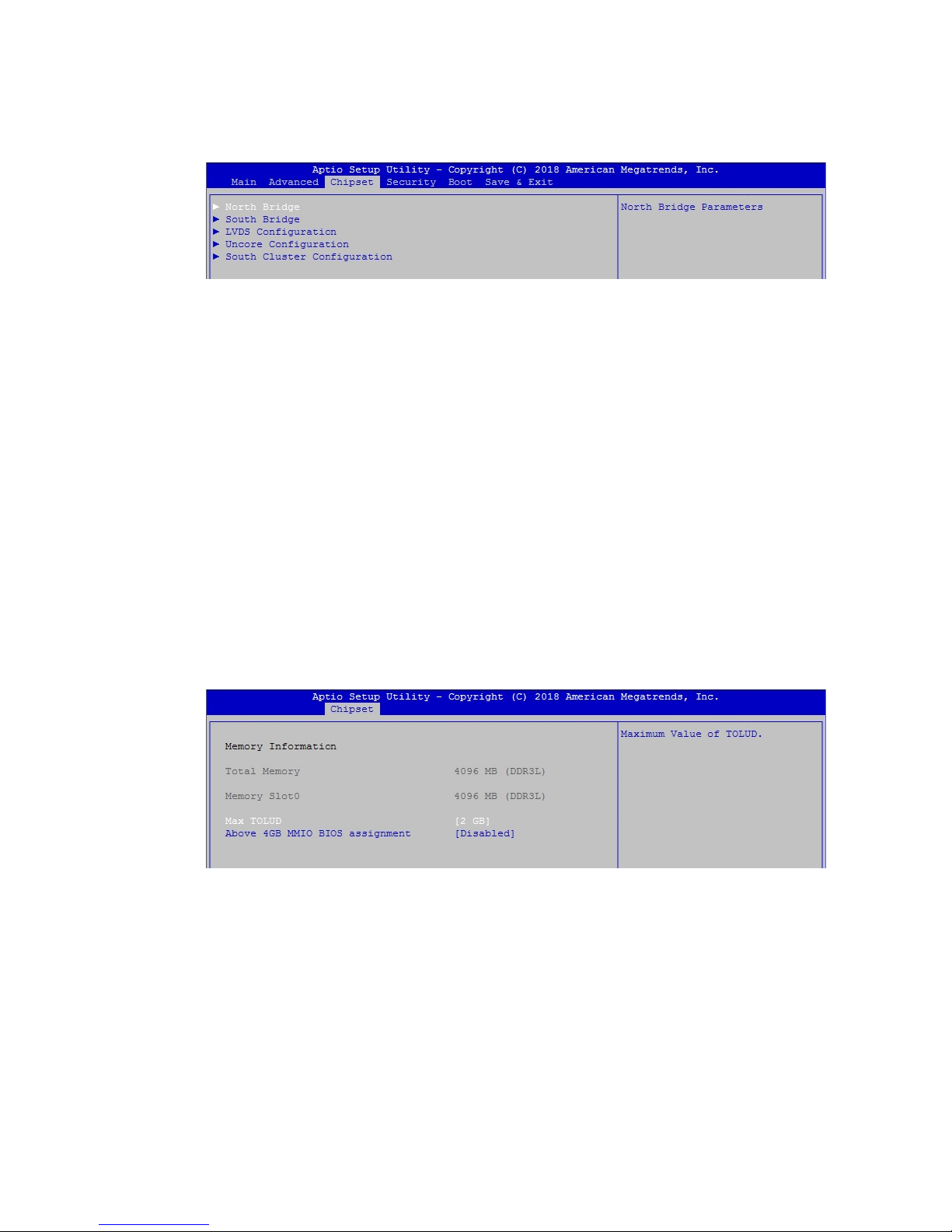
4.3.8 CSM Conguration
Figure 4-3-8 : CSM Settings
CSM Support
Enable/Disable CSM support.
GateA20 Active
UPON REQUEST - GA20 can be disabled using BIOS services. ALWAYS - do
not allow disabling GA20; this option is useful when any RT code is executed
above 1MB.
INT19 Trap Response
BIOS reaction on INT19 trapping by Option ROM : IMMEDIATE - execute the
trap right away; POSTPONED - execute the trap during legacy boot.
Boot option lter
This option controls Legacy/UEFI ROMs priority.
Network
Controls the execution of UEFI and Legacy PXE OpROM.
Storage
Controls the execution of UEFI and Legacy Storage OpROM.
Video
Controls the execution of UEFI and Legacy Video OpROM.
Other PCI devices
Determines OpROM execution policy for devices other than Network, Storage,
or Video.
Page 50
44
©Vecow EMBC-2000 User Manual
BIOS SETUP
Figure 4-4 : Chipset
North Bridge
North Bridge Parameters.
South Bridge
South Bridge Parameters.
LVDS Conguration
LVDS Conguration.
Uncore Conguration
Uncore Conguration.
South Cluster Conguration
South Cluster Conguration.
4.4 Chipset
4.4.1 North Bridge
Figure 4-4-1 : North Bridge Settings
Max TOLUD
Maximum Value of TOLUD.
Above 4GB MMIO BIOS assignment
Enable/Disable above 4GB MemoryMappedIO BIOS assignment. This is
disabled automatically when Aperture Size is set to 2048MB.
Page 51
45
©Vecow EMBC-2000 User Manual
BIOS SETUP
4.4.2 South Bridge
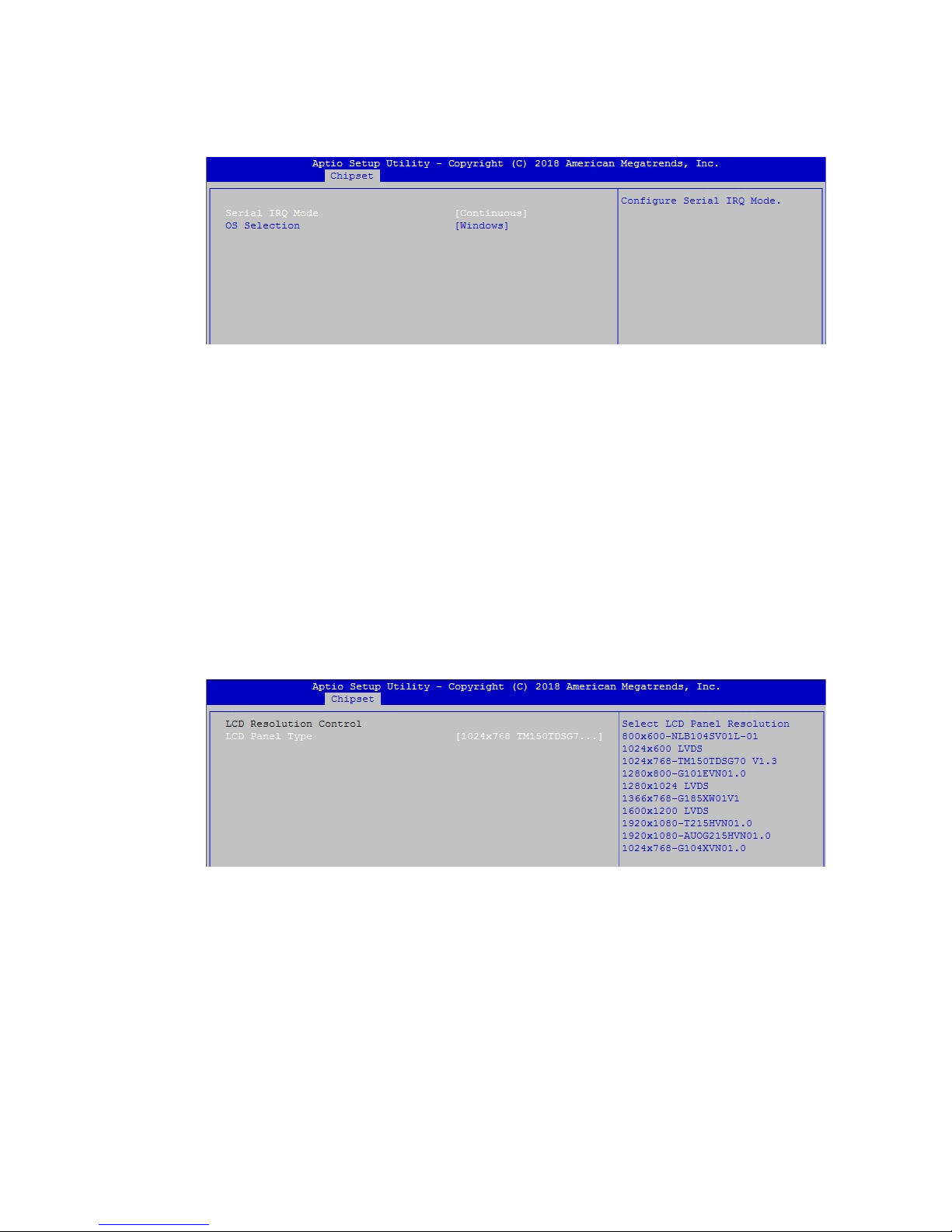
Figure 4-4-2 : South Bridge
Serial IRQ Mode
Congure Serial IRQ Mode.
OS Selection
Select the target OS. There are some settings difference between windows and
Linux. We advise you to change this option with the OS you will use.
4.4.3 LVDS Conguration
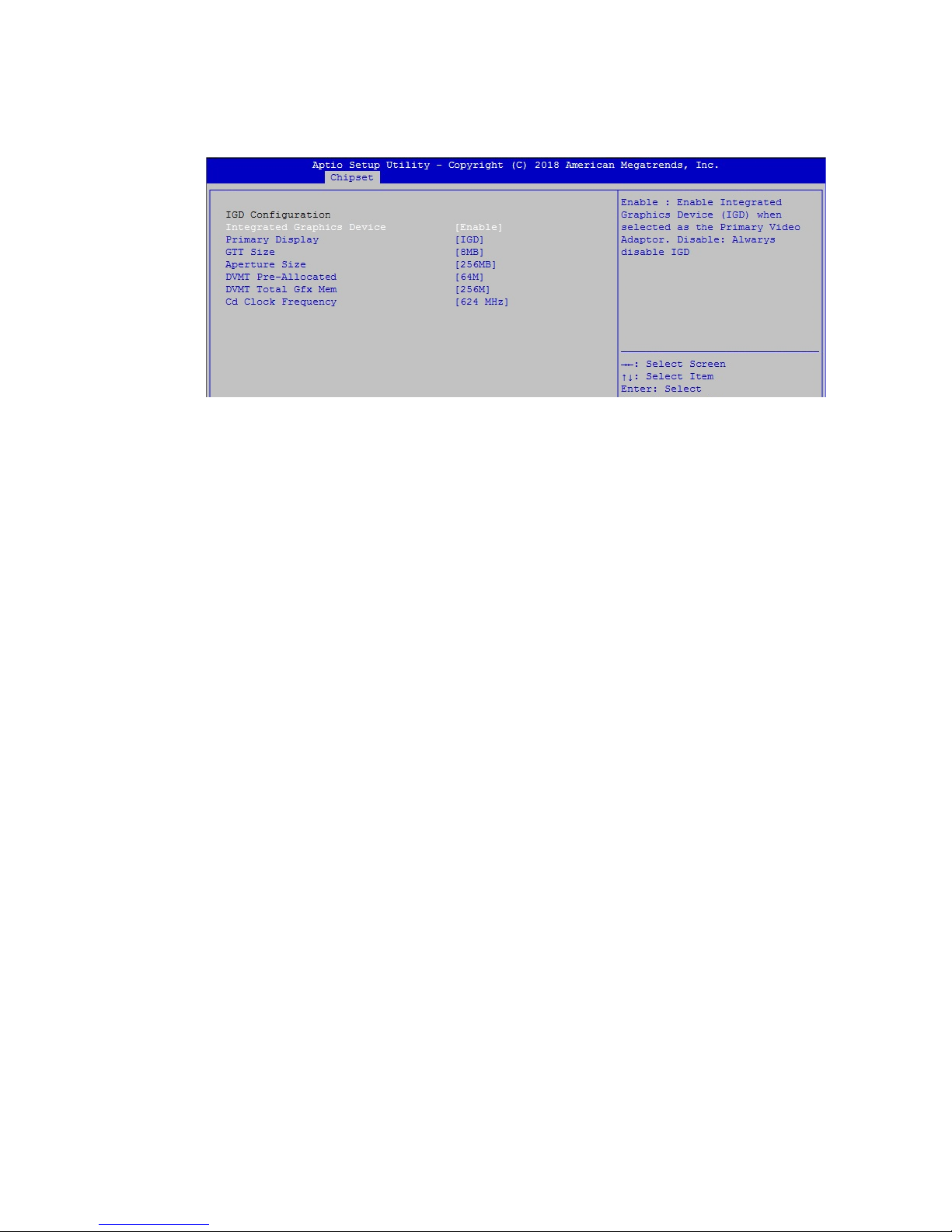
Figure 4-4-3 : LVDS Panel Settings
The LVDS Conguration option will be present if LVDS panel is connected on
system.
LCD Panel Type
Select LCD Panel Resolution.
Page 52
46
©Vecow EMBC-2000 User Manual
BIOS SETUP
4.4.4 Uncore Conguration
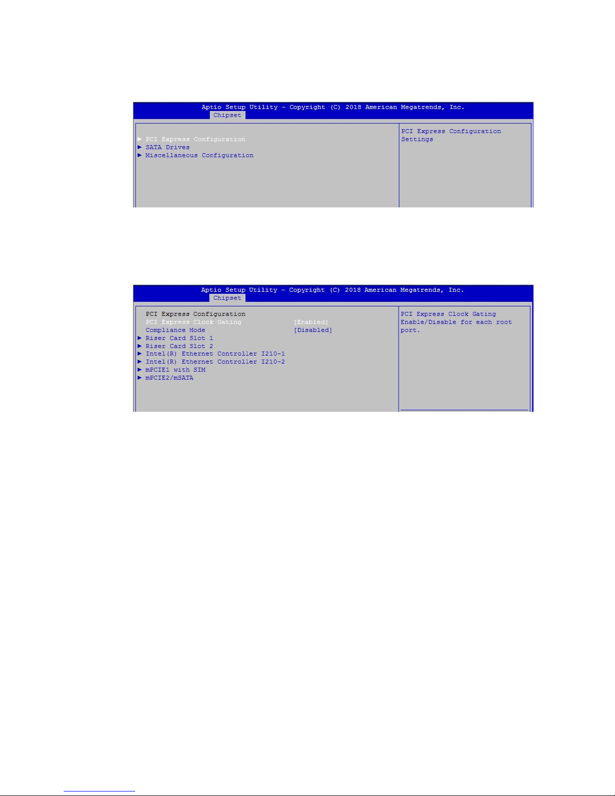
Figure 4-4-4 : Uncore Conguration
Integrated Graphics Device
Enable : Enable Integrated Graphics Device (IGD) when selected as the Primary
Video Adaptor. Disable : Always disable IGD.
Primary Display
Select which of IGD/PCI Graphics device should be Primary Display
GTT Size
Select the GTT Size
Aperture Size
Select the Aperture Size
DVMT Pre-Allocated
Select DVMT 5.0 Pre-Allocated (Fixed) Graphics Memory size used by the
Internal Graphics Device
DVMT Total Gfx Mem
Select DVMT5.0 Total Graphic Memory size used by the Internal Graphics
Device
Cd Clock Frequency
Select the highest Cd Clock frequency supported by the platform
Page 53
47
©Vecow EMBC-2000 User Manual
BIOS SETUP
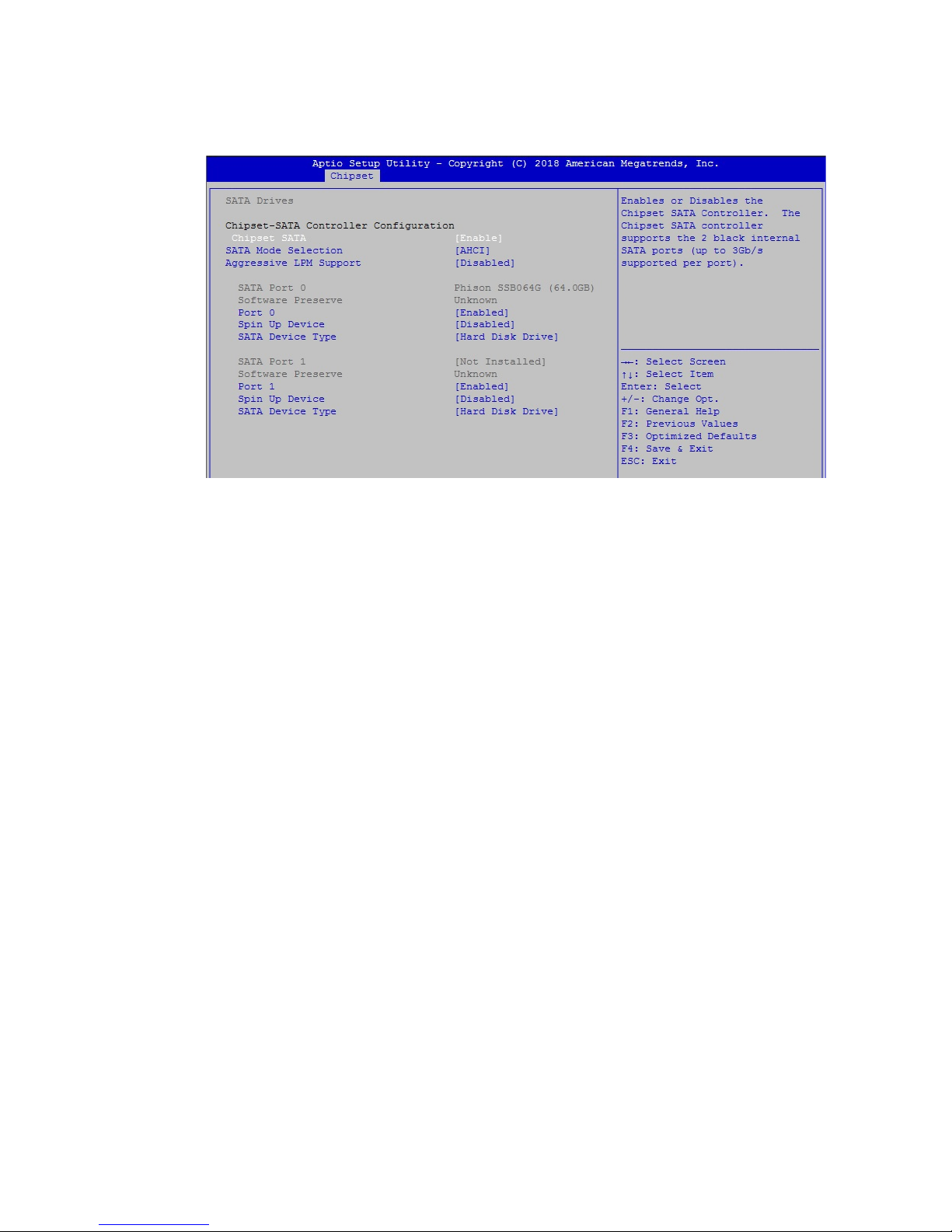
Figure 4-4-5 : South Cluster Settings
4.4.5.1 PCI Express Conguration
Figure 4-4-5-1 : PCI Express Settings
PCI Express Clock Gating
PCI Express Clock Gating Enable/Disable for each root port.
Compliance Mode
Compliance Mode Enable/Disable.
Riser Card Slot
Riser Card Slot settings.
Intel(R) Ethernet Controller I210
Intel(R) Ethernet Controller I210 Settings
Mini PCIe Slot with SMI
Mini PCIe Slot with SIM settings.
Mini PCIe/mSATA
Mini PCIe/mSATA Slot Settings.
4.4.5 South Cluster conguration
Page 54
48
©Vecow EMBC-2000 User Manual
BIOS SETUP
4.4.5.2 SATA Drivers
Figure 4-4-5-2 : SATA Devices Settings
Chipset SATA
Enables or Disables the Chipset SATA Controller. The Chipset SATA controller
supports the 2 black internal SATA ports (up to 3Gb/s supported per port).
SATA Mode Selection
Determines how SATA controller(s) operate.
Aggressive LPM Support
Enable PCH to aggressively enter link power state.
Options for each SATA port :
Port 0/1
Enable or Disable SATA Port.
Spin up Device
If enabled for any of ports Staggerred Spin Up will be performed and only the
drives which have this option enabled will spin up at boot. Otherwise all drives
spin up at boot.
SATA Device Type
Identify the SATA port is connected to Solid State Drive or Hard Disk Drive.
Page 55
49
©Vecow EMBC-2000 User Manual
BIOS SETUP
4.4.5.3 Miscellaneous Conguration
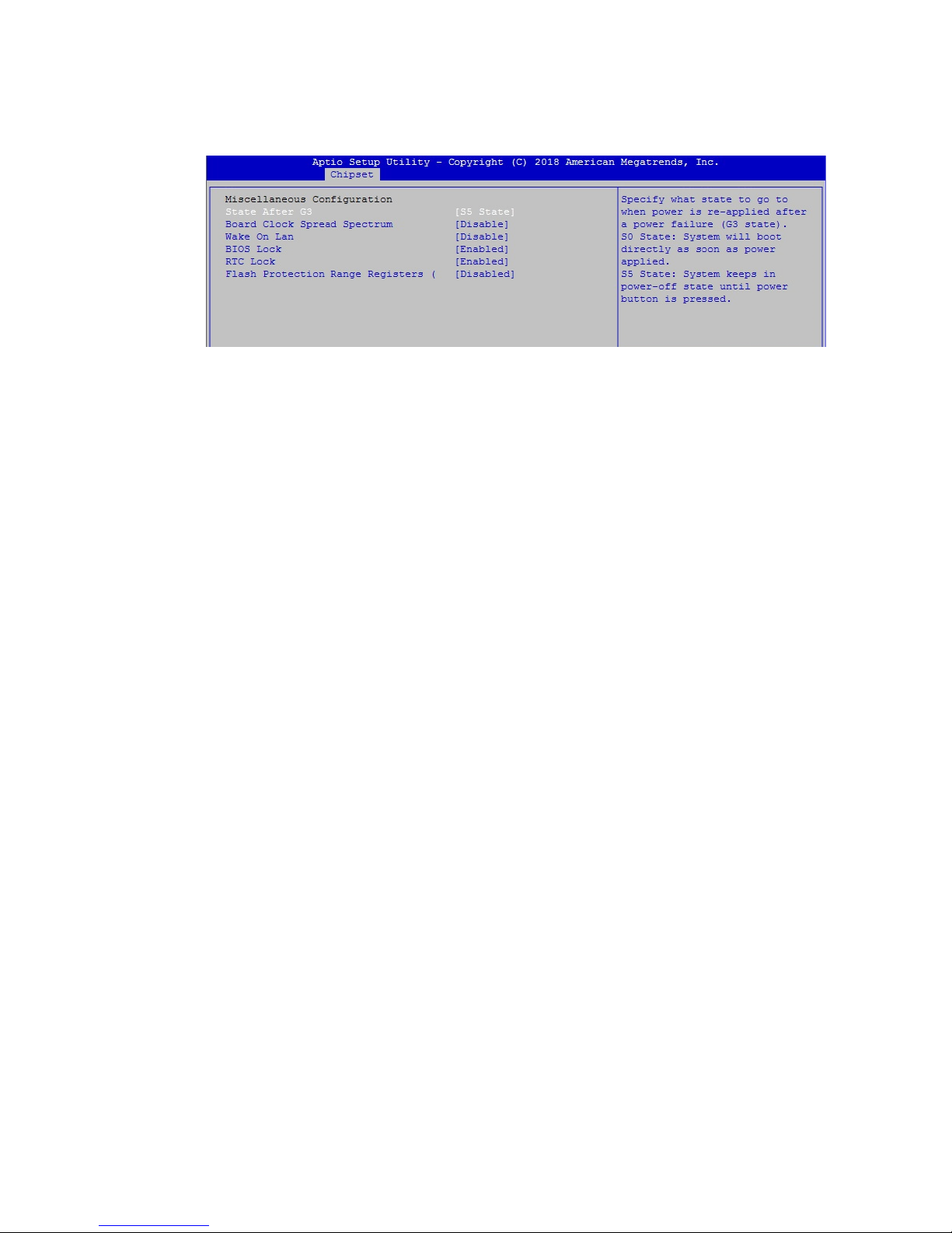
Figure 4-4-5-3 : Miscellaneous Conguration
State After G3
Specify what state to go to when power is re-applied after a power failure
(G3 state).
S0 State : System will boot directly as soon as power applied.
S5 State : System keeps in power-off state until power button is pressed.
Board Clock Spread Spectrum
Enable Clock Chip's Spread Spectrum feature.
Wake On Lan
Enable or Disable the Wake on Lan.
BIOS Lock
Enable/Disable the SC BIOS Lock Enable feature. Required to be enabled to
ensure SMM protection of ash.
RTC Lock
Enable will lock bytes 38h-3Fh in the lower/upper 128-byte bank of RTC RAM.
Flash Protection Range Registers (FPRR)
Enable Flash Protection Range Registers.
Page 56
50
©Vecow EMBC-2000 User Manual
BIOS SETUP
4.5 Security
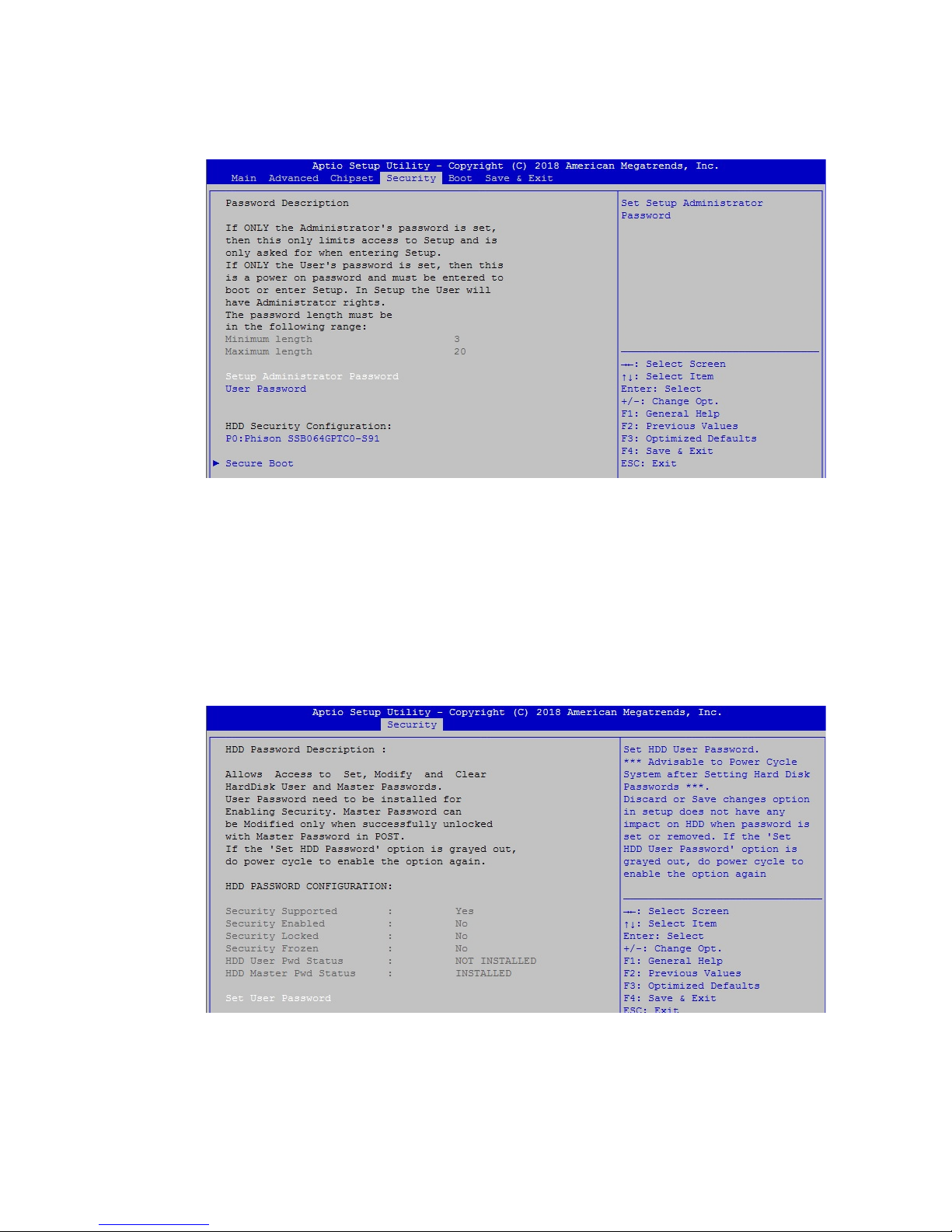
Setup Administrator Password
Set Setup Administrator Password
User Password
Set User Password
Secure Boot
Customizable Secure Boot Settings.
Figure 4-5 : BIOS Security Menu
4.5.1 HDD Security Conguration
Set User Password
Set HDD user password.
***Advisable to Power Cycle System after Setting Hard Disk Passwords***
Discard or save changes option in setup dies not have any impact on HDD
when password is set or removed. If the "Set HDD User Password" option is
grayed out, do power cycle to enable the option again.
Figure 4-5-1 : HDD Security Settings
Page 57
51
©Vecow EMBC-2000 User Manual
BIOS SETUP
4.5.2 Security Boot
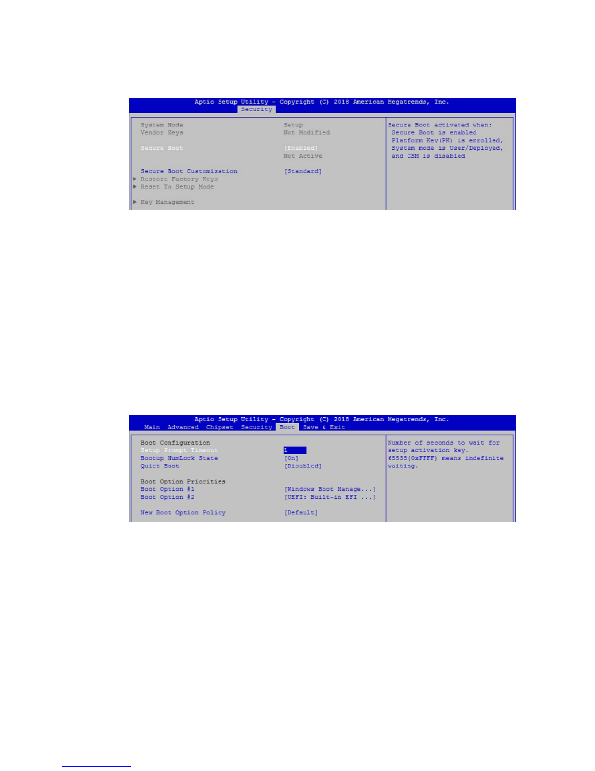
Secure Boot
Secure Boot activated when : Secure Boot is enabled Platform Key (PK) is
enrolled, System mode is User/Deployed, and CSM is disabled.
Secure Boot Customization
Secure Boot mode – Custom & Standard, Set UEFI Secure Boot mode to
STANDARD mode or CUSTOM mode, this change is effect after save. And after
reset, the mode will return to STANDARD mode.
Key Management
Enables expert users to modify Secure Boot Policy variables without full
authentication.
4.6 Boot
Figure 4-5-2 : Security Boot Settings
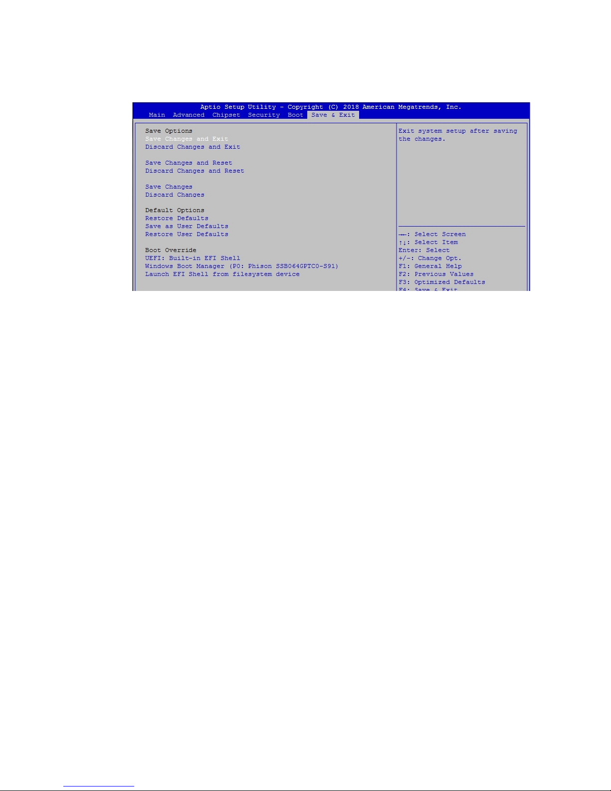
Setup Prompt Timeout
Number of seconds to wait for setup activation key. 65535 (0xFFFF) means
indenite waiting.
Bootup NumLock State
Select the keyboard NumLock state.
Quiet Boot
Enables or disables Quiet Boot option.
Boot Option #x
Sets the system boot order.
New Boot Option Policy
Controls the placement of newly detected UEFI boot options.
Figure 4-6 : BIOS Boot Menu
Page 58
52
©Vecow EMBC-2000 User Manual
BIOS SETUP
4.7 Save & Exit
Save Changes and Exit
Exit system setup after saving the changes.
Discard Changes and Exit
Exit system setup without saving any changes.
Save Changes and Reset
Reset the system after saving the changes.
Discard Changes and Reset
Reset system setup without saving any changes.
Save Changes
Save Changes done so far to any of the setup options.
Discard Changes
Discard Changes done so far to any of the setup options.
Default options :
Restore Defaults
Restore/Load Default values for all the setup options.
Save as User Defaults
Save the changes done so far as User Defaults.
Restore User Defaults
Restore the User Defaults to all the setup options.
Figure 4-7 : BIOS Save and Exit Menu
Page 59
53
©Vecow EMBC-2000 User Manual
Appendix A
A.1 Function Description
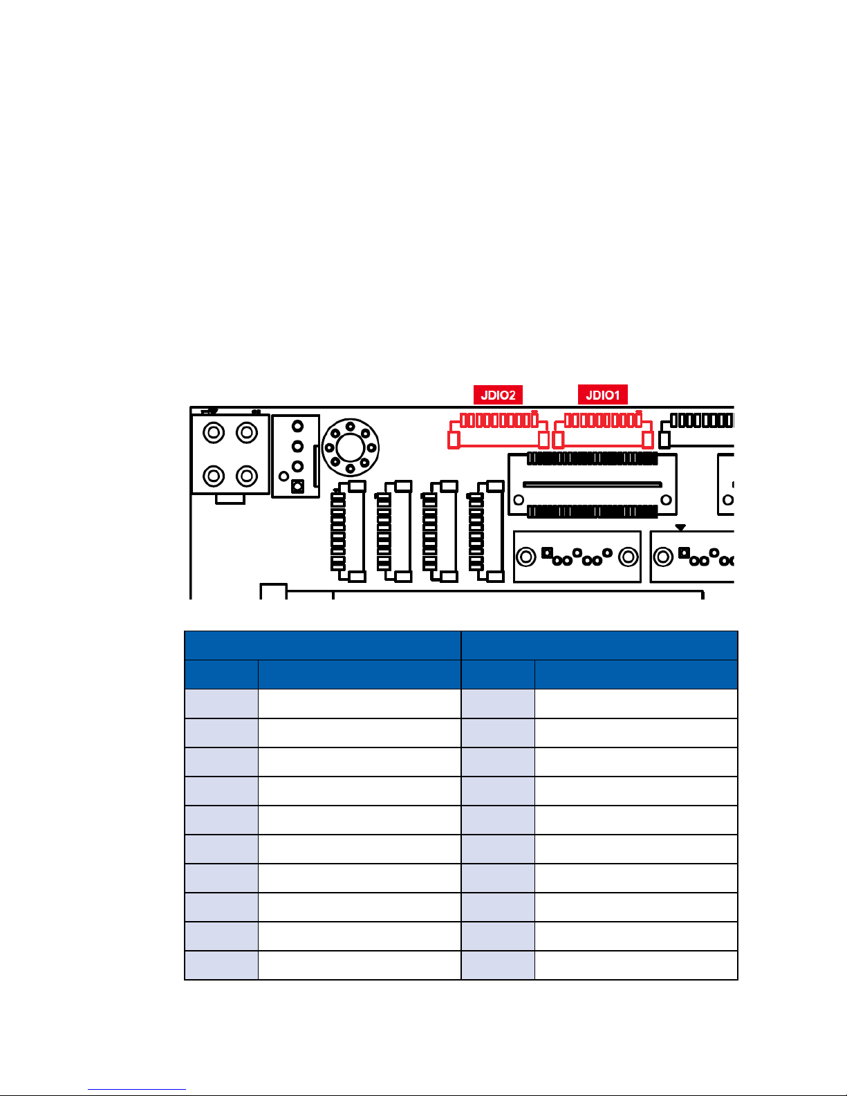
The EMBC-2000 offers a 16-bit GPIO a pair of 10-bit internal connector and a
watchdog timer. GPIO denition is shown below:
APPENDIX A : Isolated DIO Guide
JDIO1 JDIO2
Pin No. GPIO Denition Pin No. GPIO Denition
1 GPIO 0 1 GPIO 8
2 GPIO 1 2 GPIO 9
3 GPIO 2 3 GPIO 10
4 GPIO 3 4 GPIO 11
5 GPIO 4 5 GPIO 12
6 GPIO 5 6 GPIO 13
7 GPIO 6 7 GPIO 14
8 GPIO 7 8 GPIO 15
9 NC 9 NC
10 NC 10 NC
A
Page 60
54
©Vecow EMBC-2000 User Manual
Appendix A
A.3 Sample
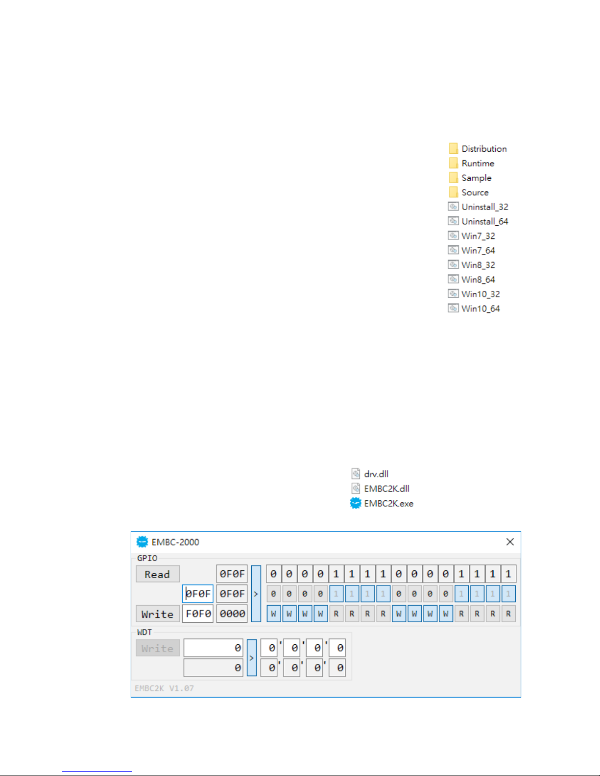
Execute DIO Demo tool (EMBC2K.exe).
Sample EMBC2K.exe, as shown below:
A.2 Software Package Contain
Distribution folder include x32 and x64 versions, use batch le for installation.
There are included as fallowed:
Win7_32.bat:
Installation for 32-bit driver
Win7_64.bat:
Windows update package which driver required
(need to restart), and Installation for 64-bit driver
Win8_32.bat, Win8_64.bat:
Installation for driver, and guideline to Framework
3.5 distribution for sample
Win10_32.bat, and Win10_64.bat:
Installation for driver, and
installation to Framework 3.5 distribution for sample
Uninstall_32.bat, and Uninstall_64.bat:
Uninstallation for driver
Run batch le as Administrator.
Support Windows 7 above.
Make sure Windows version before installation.
Runtime folder include head le for software developer or System Integration.
Sample folder include sample program, driver library, and API library.
Source folder include sample program source code that compile on Visual
Studio 2008.
Page 61

55
©Vecow EMBC-2000 User Manual
Appendix A
GPIO group:
Read button:
Set GPIO conguration to get GPIO state.
Write button:
Set GPIO conguration to set GPIO state.
GPIO output text:
User setting, GPIO output state by hexadecimal bitmask - High/Low.
Use for Write button activate.
GPIO writable text:
User setting, GPIO writable of GPIO conguration by hexadecimal bitmask yes/no.
Use for Read/Write button activate.
GPIO input text (read only):
GPIO input state by hexadecimal bitmask - High/Low.
Use for Read button activate.
GPIO text (read only):
GPIO output state with input state and conguration.
Use for Write button activate.
GPIO output text (read only):
GPIO output state with conguration.
Use for Write button activate.
GPIO input pin check button (read only, pin 18 ~ pin 11, pin 8 ~ pin 1):
GPIO input pin state
Use for Read button activate.
GPIO output pin check button (pin 18 ~ pin 11, pin 8 ~ pin 1):
User setting, GPIO output pin state
Use for Write button activate.
GPIO pin writable check button (pin 18 ~ pin 11, pin 8 ~ pin 1):
User setting, GPIO pin writable of GPIO conguration.
Use for Read/Write button activate.
WDT group:
Write button:
Set WDT when WDT setup text is valid.
Stop button:
Cancel WDT and counting.
Use after Write button action.
WDT setup text:
User setting, WDT value, unit: second.
Use for Write button activate.
WDT counting text (read only):
WDT counting by program timer after set WDT.
Shown after Write button action.
WDT setup day format texts (user setting):
User setting, WDT value, format: day‘hour’minute’second.
WDT counting day format text (read only):
WDT counting, format: day‘hour’minute’second.
Page 62

56
©Vecow EMBC-2000 User Manual
Appendix B
B
APPENDIX B : Software Functions
B.1 Driver API Guide
In Runtime folder, on EMBC2K.h:
_DLL_IMPORT_ denition is used on LoadLibrary API for EMBC2K.dll.
EMBC2K_EXPORTS denition is used on EMBC2K.dll building.
Otherwise, that is used to compile with EMBC2K.lib
BOOL Initial()
Initial machine for GPIO, and watchdog timer
Return:
TRUE (1): Success;
FALSE (0): Fail (Driver not exists, or initial error (version is too old, or
machine not match))
BOOL GetGPIOCong(WORD *Mask)
Get GPIO conguration (by variable)
Mask ([15:0]): In/Out, pin setting by hexadecimal bitmask
1: Output; 0: Input
Return :
TRUE (1): Success;
FALSE (0): Fail (Initial error, or call by pointer error, or hardware problem)
BOOL SetGPIOCong(WORD Mask)
Set GPIO conguration
Mask ([15:0]): In/Out, pin setting by hexadecimal bitmask
1: Output; 0: Input
Return :
TRUE (1): Success;
FALSE (0): Fail (Initial error, or hardware problem)
BOOL GetGPIO(WORD *DI)
Get GPIO input
DI ([15:0]): Input state, pin setting by hexadecimal bitmask
1: High; 0: Low
Return :
TRUE (1): Success;
FALSE (0): Fail (Initial error, or call by pointer error, or hardware problem)
Page 63

57
©Vecow EMBC-2000 User Manual
Appendix B
BOOL SetGPIO(WORD DO)
Set GPIO output
DO ([15:0]): output state, pin setting by hexadecimal bitmask
1: High; 0: Low
Return:
TRUE (1): Success;
FALSE (0): Fail (Initial error, or hardware problem)
BOOL GetWDT(DWORD *WDT)
Get watchdog timer setup
WDT: watchdog timer setup
Unit: second. (Range: 0 ~ 65535 sec, 1093 ~ 65535 min (=65580 ~
3932100 sec))
Return:
TRUE (1): Success;
FALSE (0): Fail (Initial error, or call by pointer error, or hardware problem)
BOOL SetWDT(DWORD WDT)
Set watchdog timer setup
WDT: watchdog timer setup
Unit: second. (Range: 1 ~ 65535 sec, 1093 ~ 65535 min (=65580 ~
3932100 sec))
Return:
TRUE (1): Success;
FALSE (0): Fail (Initial error, or setup 0 error, or hardware problem)
BOOL CancelWDT()
Cancel watchdog timer
Return:
TRUE (1): Success;
FALSE (0): Fail (Initial error, or hardware problem)
Page 64
58
©Vecow EMBC-2000 User Manual
Appendix C
C
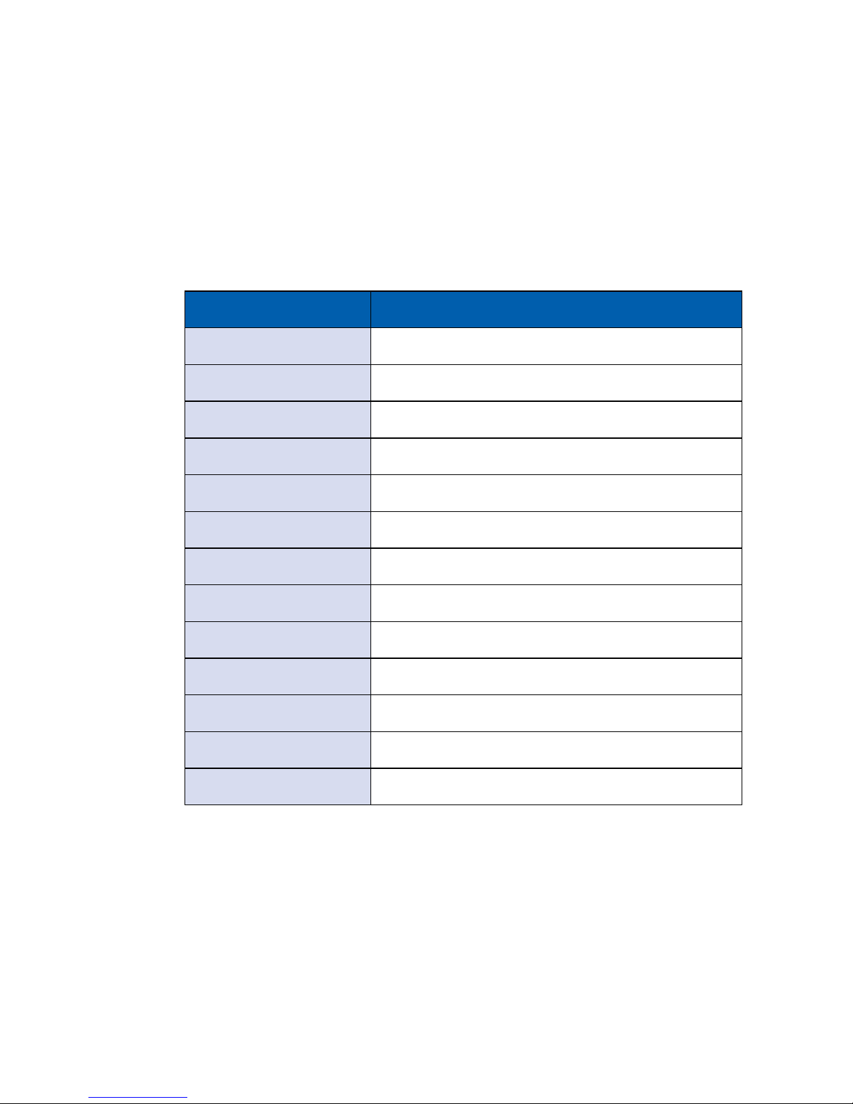
APPENDIX C : Power Consumption
Testing Board EMBC-2000
RAM DDR3L 1866 8GB x1
USB-1 USB Keyboard Microsoft Wired Keyboard 600
USB-2 USB Mouse Logitech M105
USB-3 USB Flash ADATA 3.0 16GB
USB-4 USB Flash Transecnd 3.0 16GB
CFAST N/A
SATA 0 Intel
®
SSD E5400s 120GB
SATA 1 Toshiba HDD MQ01ABD050 500GB
LAN 1 (I210) 1.0Gbps
LAN 2 (I210) 1.0Gbps
Graphics Output HDMI
Power Plan Balance (Windows 10 Power Plan)
Power Source Chroma 62006P-100-25
Page 65
59
©Vecow EMBC-2000 User Manual
Appendix C
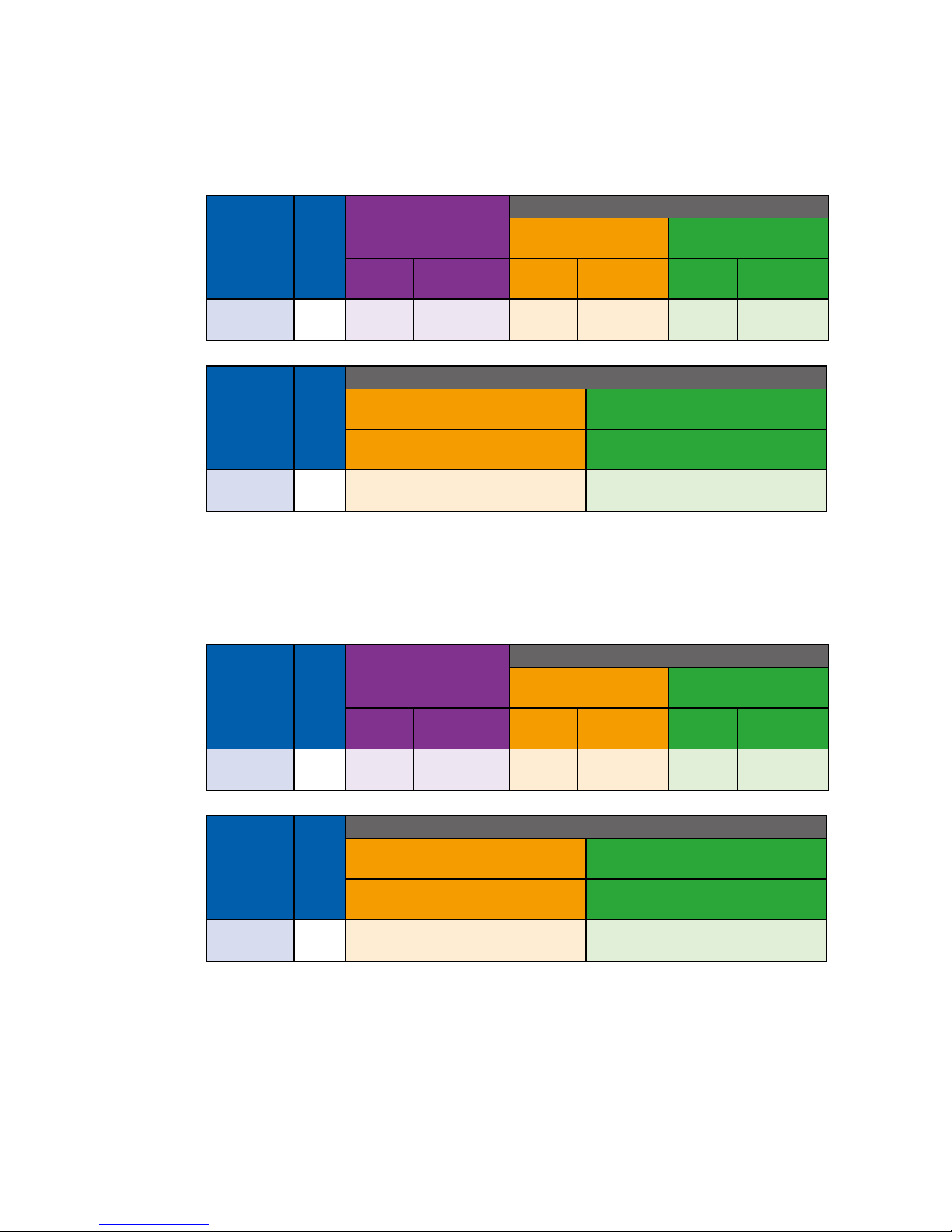
C.1 Intel Atom® x7-E3950 1.6GHz (Apollo Lake)
(2M Cache, up to 2.00GHz) Without Turbo Mode
CPU
Power
Input
Standby Mode
Power on and boot to Win 7 (64-bit)
Sleep Mode
idle status CPU
usage less 3%
Max
Current
Max
Consumption
Max
Current
Max
Consumption
Max
Current
Max
Consumption
Apollo Lake
x7-E3950
12V 0.247A 02.96W 0.186A 02.23W 0.838A 10.06W
CPU
Power
Input
Power on and boot to Win 7 (64bit)
Run 100% CPU
usage without 3D
Run 100% CPU
usage with 3D
Max
Current
Max
Consumption
Max
Current
Max
Consumption
Apollo Lake
x7-E3950
12V 1.119A 13.43W 1.603A 19.24W
C.2 Intel Atom® x7-E3950 1.6GHz (Apollo Lake)
(2M Cache, up to 2.00GHz) With Turbo Mode
CPU
Power
Input
Standby Mode
Power on and boot to Win 7 (64-bit)
Sleep Mode
idle status CPU
usage less 3%
Max
Current
Max
Consumption
Max
Current
Max
Consumption
Max
Current
Max
Consumption
Apollo Lake
x7-E3950
12V 0.274A 03.29W 0.187A 02.24W 0.885A 10.62W
CPU
Power
Input
Power on and boot to Win 7 (64bit)
Run 100% CPU
usage without 3D
Run 100% CPU
usage with 3D
Max
Current
Max
Consumption
Max
Current
Max
Consumption
Apollo Lake
x7-E3950
12V 1.271A 15.25W 1.702A 20.42W
Page 66
60
©Vecow EMBC-2000 User Manual
Appendix D
D
APPENDIX E : Supported Memory &
Storage List
D.1 Test Item
Testing Board EMBC-2000
Memory Test Version : 5.1
Burn-in Test V8.1
Channel
Memory
Test
Burn-in
Test
Flash
BIOS
Remove
Battery
Sleep Hibermate Reset CPU-Z
*1
(Socket 1)
PASS PASS PASS PASS PASS PASS PASS PASS
D.2 NON-ECC
Brand Info
Test Temp.
(Celsius)
Vecow 4GB 240PIN DDR3L-1333 SODIMM M340L-W28M1
25ºC
25ºC
Kingston 2GB 240PIN DDR3L-1600 SODIMM KVR16LS11S6/2
25ºC
25ºC
Kingston 4GB 240PIN DDR3L-1600 SODIMM KVR16LS11/4
25ºC
25ºC
Crucial 4GB 240PIN DDR3L-1600 SODIMM
CT51264BF160BJ.
C8FER
25ºC
25ºC
Kingston 8GB 240PIN DDR3L-1600 SODIMM KVR16LS11/8
25ºC
25ºC
ATLA 4GB 240PIN DDR3L-1866 SODIMM
AD3SST4GG6WB-
DMGEL
25ºC
25ºC
ATLA 8GB 240PIN DDR3L-1866 SODIMM
AD3SST8GSAWB-
DMGEL
25ºC
25ºC
Page 67
61
©Vecow EMBC-2000 User Manual
Appendix D
D.3 Supported Storage Device List
Type Vendor Model Capacity
mSATA Intel Intel-310 SSDMAEMC080G2 80GB
SATA SSD
Kingston SUV400S37/120G 120GB
Innodisk 3MG2-P DGS25-64GD81BC1QC 64GB
Intel SSD 540s SSDSC2KW120H6 120GB
Intel SSD E 5400s SSDSC2KR120H6 120GB
MEMXPRO 2.5" SSD M3A 128GB 128GB
LITE-ON K8-L1256 256GB
LITE-ON K8-L1512 512GB
SATA HDD TOSHIBA MQ01ABF050 500GB
** If more help is needed, please contact Vecow Technical Support.**
Page 68

For further support information, please visit www.vecow.com
This document is released for reference purpose only.
All product offerings and specications are subject to change without prior notice.
No part of this publication may be reproduced in any form or by any means, electric, photocopying, or recording,
without prior authorization from the publisher.
The rights of all the brand names, product names, and trademarks belong to their respective owners.
© Vecow Co., Ltd. 2019. All rights reserved.
 Loading...