

Page 1

USER
Manual
USER
Manual
1.1.0 Edition 20181022
VIG-100
Industrial-grade Wireless IoT Gateway with Arm® Cortex®-A7
Rugged, Compact, NB-IoT for LPWAN, -25°C to 70°C Operation
Page 2
ii
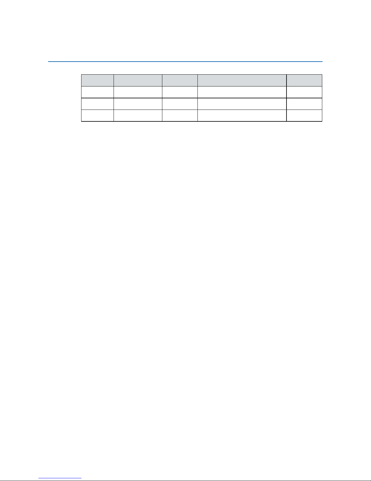
Version Date Page Description Remark
0.10 09/07/2018 All Preliminary Release
1.00 09/17/2018 All Ofcial Release
1.10 10/22/2018 P39-47 Update
Record of Revision
Page 3

iii
This manual is released by Vecow Co., Ltd. for reference purpose only. All
product offerings and specications are subject to change without prior notice.
It does not represent commitment of Vecow Co., Ltd. Vecow shall not be liable
for direct, indirect, special, incidental, or consequential damages arising out of
the use of the product or documentation or any infringements upon the rights of
third parties, which may result from such use.
This equipment has been tested and found to comply with the limits for a Class
A digital device, pursuant to part 15 of the FCC Rules. These limits are designed
to provide reasonable protection against harmful interference when the
equipment is operated in a commercial environment. This equipment generates,
uses, and can radiate radio frequency energy, and if it is not installed and used
in accordance with the instruction manual, it may cause harmful interference to
radio communications. Operation of this equipment in a residential area is likely
to cause harmful interference in which case the user will be required to correct
the interference at his own expense.
FCC
The products described in this manual complies with all applicable European
Union (CE) directives if it has a CE marking. For computer systems to
remain CE compliant, only CE-compliant parts may be used. Maintaining CE
compliance also requires proper cable and cabling techniques.
CE
This document contains proprietary information protected by copyright. No part
of this publication may be reproduced in any form or by any means, electric,
photocopying, recording or otherwise, without prior written authorization
by Vecow Co., Ltd. The rights of all the brand names, product names, and
trademarks belong to their respective owners.
Disclaimer
Declaration of Conformity
Copyright and Trademarks
Page 4
iv
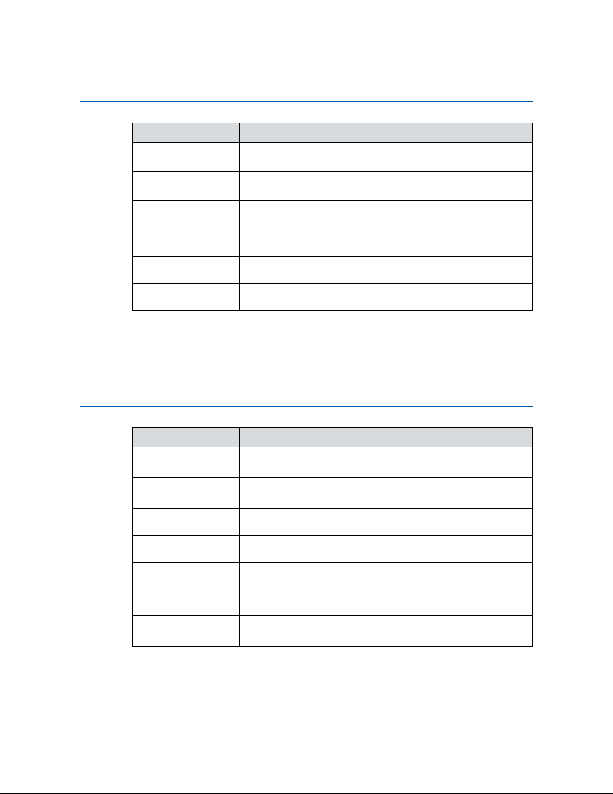
Part Number Description
VIG-120M
VIG-100, Arm® Cortex™-7, 2 M12 LAN, 1 USB, 4 COM,
2 CAN Bus, 8 GPIO
VIG-120
VIG-100, Arm
®
Cortex™-7, 2 LAN, 1 USB, 4 COM,
2 CAN Bus, 8 GPIO
VIG-110M
VIG-100, Arm
®
Cortex™-7, 2 M12 LAN, 1 USB, 4 COM,
8 GPIO
VIG-110 VIG-100, Arm
®
Cortex™-7, 2 LAN, 1 USB, 4 COM, 8 GPIO
VIG-100M VIG-100, Arm
®
Cortex™-7, 2 M12 LAN, 1 USB, 2 COM
VIG-100 VIG-100, Arm
®
Cortex™-7, 2 LAN, 1 USB, 2 COM
Order Information
Part Number Description
PWA-12W-US 12W, 12V, 90V AC to 264V AC Power Adapter with 3-pin
Terminal Block (US Type)
PWA-12W-EU 12W, 12V, 90V AC to 264V AC Power Adapter with 3-pin
Terminal Block (EU Type)
Serial Cable RJ45 to DB9 Female Serial Cable, 100cm
Wallmount Wallmount Kit
NB-IoT Module LPWAN NB-IoT Module with Antenna
4G Module Mini PCIe 4G/GPS Module with Antenna
WiFi & Bluetooth
for ARM
WiFi & Bluetooth Module (1T1R) with Antenna
Order Accessories
Page 5

v
Table of Contents
CHAPTER 1
GENERAL INTRODUCTION 1
1.1 Overview 1
1.2 Features 2
1.3 Product Specication 2
1.3.1 Specications of VIG-120M 2
1.3.2 Specications of VIG-120 3
1.3.3 Specications of VIG-110M 5
1.3.4 Specications of VIG-110 6
1.3.5 Specications of VIG-100M 7
1.3.6 Specications of VIG-100 8
1.4 Mechanical Dimension 10
1.4.1 Dimensions of VIG-120M 10
1.4.2 Dimensions of VIG-120 10
1.4.3 Dimensions of VIG-110M 11
1.4.4 Dimensions of VIG-110 11
1.4.5 Dimensions of VIG-100M 12
1.4.6 Dimensions of VIG-100 12
CHAPTER 2
GETTING TO KNOW YOUR VIG-100 13
2.1 Packing List 13
2.2 Front Panel I/O & Functions 14
2.3 Top Panel I/O & Functions 19
2.4 Bottom Panel I/O & Functions 20
2.5 Main Board Expansion Connectors 23
2.6 Main Board Jumper & Deep Switch Settings 27
2.7 GPIO Pin Assignments Table 29
Page 6

vi
CHAPTER 3 SYSTEM SETUP 30
3.1 How to Open Your VIG-100 30
3.2 Installing MicroSD Card 31
3.3 Installing Mini PCIe Card 32
3.4 Installing LPWAN NB-IoT Module 33
3.5 Installing Antenna Cable 34
3.6 Installing SIM Card 35
3.7 Mounting Your VIG-100 36
CHAPTER 4 SOFTWARE SETUP 39
4.1 Console Port Login 39
4.2 COM Port 42
4.3 I2C interface 43
4.4 GPIO & LED 43
4.5 Network 45
4.6 CANbus 46
APPENDIX A : POWER CONSUMPTION 47
Page 7

1
GENERAL INTRODUCTION
1
GENERAL INTRODUCTION
VIG-100 is a compact and rugged Wireless IoT Gateway, the first arm-based
elite in Vecow offering list. Powered by Industrial-grade Arm® Cortex®-A7
processor, multiple I/O congurations to meet variety of requirements, Optional
NB-IoT module (Narrow Band Internet of Thing) for system-ready LPWAN (LowPower Wide-Area Network) applications, 6V to 40V DC wide range power input,
fanless design supporting -25°C to 70°C operating temperature, Vecow VIG-100
stands itself out in this AIoT era.
Based on high-performance and energy-saving Arm® Cortex®-A7 processor,
versatile connectivity including dual Ethernet with rugged M12 connectors, 4
COM RS-232/422/485 for simple networking through connected devices, 1 Mini
PCIe for additional USB or SIM expansions, 2 CAN Bus, 1 USB 2.0 for On-TheGo support, 8 GPIO and MicroSD supporting up to 128 GB for configuration
backup, Optional NB-IoT module based on LPWAN technique and close
relationship with 5G Mobile Networks which is going to be booming in a decade,
Vecow VIG-100 is a great choice for IoT related seamless data acquisition and
edge computing embedded applications.
Combing the rugged reliability for seamless operations in harsh industrial
environments, 6V to 40V wide range DC power input allowing duties in
constrained conditions, Fanless -25°C to 70°C operating temperature, external
SIM for WiFi, 4G, LTE, GPRS and UMTS connections keeping stable network
and 24/7 operation, dual Ethernet with rugged M12 connectors, compliant with
FCC, CE, anti-shock and anti-vibration, Vecow VIG-100 is your trusted enabler
in any industrial oriented IoT developments.
VIG-100 is built with wireless connectivity including multiple COM, CAN
Bus, SIM, Mini PCIe, Ethernet with rugged M12 connectors ensuring simple
networking, a wide DC input range of 6V to 40V, Fanless, -25°C to 70°C
operating temperature, compliant with CE, FCC anti-shock and anti-vibration,
Vecow VIG-100 Industrial-grade Wireless IoT Gateway is your ideal choice for
expanding reach to your IoT projects.
1.1 Overview
Page 8
2
GENERAL INTRODUCTION
©Vecow VIG-100 User Manual
1.2 Features
• Industrial grade Arm® Cortex®-A7 696MHz processor
• 6V to 40V wide range DC power input
• -25°C to 70°C Operating Temperature
• Dual Ethernet with rugged M12 Connection
• 4 COM RS-232/422/485, 2 CAN Bus, 1 USB (OTG)
• 8 GPIO, 1 Console, 8 User Programming LED
• External SIM Socket supports WiFi/4G/LTE/GPRS/UMTS
• MicroSD Socket supports up to 128GB
• Optional NB-IoT module supports system-ready LPWAN applications
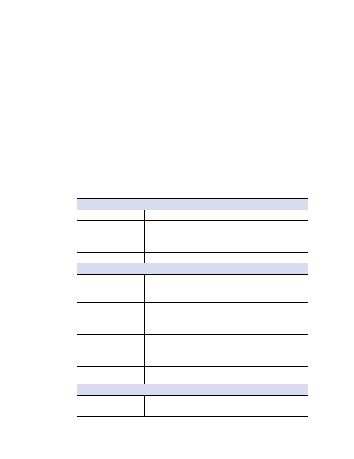
1.3 Product Specication
1.3.1 Specications of VIG-120M
System
Processor NXP i.MX6 UltraLite 696MHz Arm® Cortex®-A7 processor
Memory 1 DDR3L SDRAM, 512MB
Flash 1 NAND Flash, 512MB
EEPROM 1, up to 16KB
OS Debian Stretch R01-4.9.11
I/O Interface
Ethernet 2 10/100Mbps Ethernet, M12 connector
Serial 4 software configurable COM RS-232/422/485 (ESD 8KV) :
2 with RJ45 connector, 2 with DB9 connector
CAN Bus 2 CAN Bus 2.0 A/B
USB 1 USB 2.0 supports OTG (External)
GPIO 8 GPIO
Console 1 independent debug console
Reset Button 2 for H/W Reset and User Programming
LED 10 for System Ready, Power Status and User Programming
Antenna • 1 Antenna for NB-IoT
• 3 Antenna for WiFi/4G/LTE/GPRS/UMTS
Expansion
Mini PCIe 1 Full-size for USB/External SIM Card
SIM Card 1 SIM Card Socket (External)
Page 9
3
GENERAL INTRODUCTION
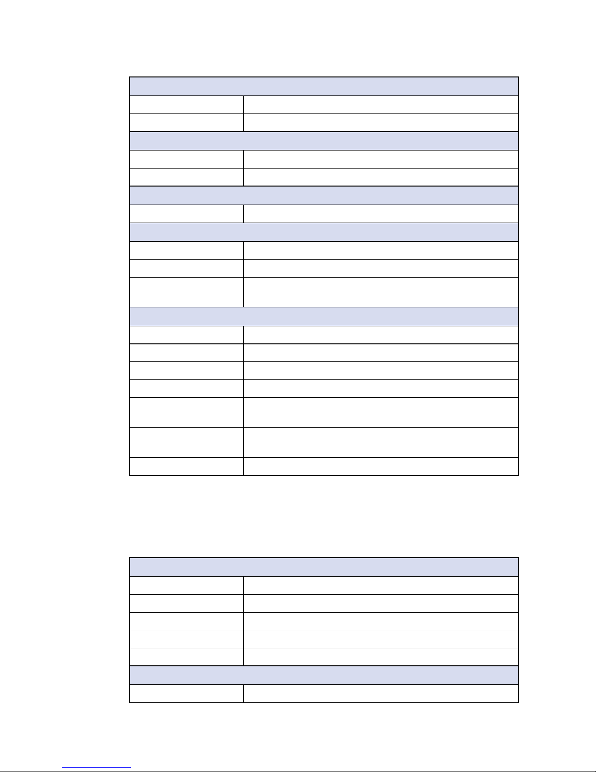
Storage
MicroSD 1, supports SDHC, up to 128GB (External)
eMMC Optional, up to 32GB
Power
Power Input 6V to 40V, DC-in
Power Interface 3-pin Terminal Block : V+, V-, Frame Ground
Others
Watchdog Timer Reset : 0.5 to 128 sec./min. per step
Mechanical
Dimensions (W) 106mm x (L) 160mm x (H) 50mm (4.2" x 6.3" x 2.0")
Weight 0.6 kg (1.32 lb)
Mounting • DIN Rail Mount
• Wallmount by mounting bracket (Optional)
Environment
Operating Temperature -25°C to 70°C (-13°F to 158°F)
Storage Temperature -40°C to 85°C (-40°F to 185°F)
Humidity 5% to 95% Humidity, non-condensing
Relative Humidity 95% at 70°C
Shock • IEC 60068-2-27
• SSD : 50G @ Wallmount, Half-sine, 11ms
Vibration • IEC 60068-2-64
• SSD : 5Grms, 5Hz to 500Hz, 3 Axis
EMC CE, FCC, EN50155, EN50121-3-2
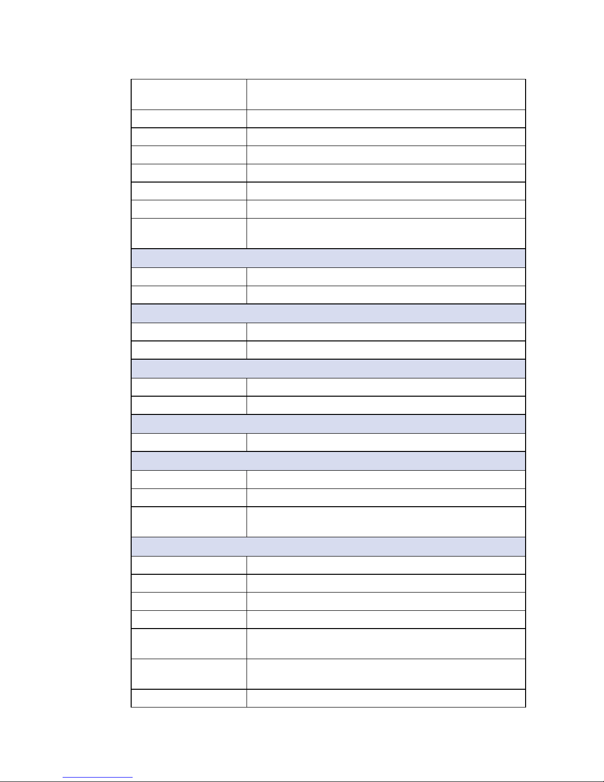
1.3.2 Specications of VIG-120
System
Processor NXP i.MX6 UltraLite 696MHz Arm® Cortex®-A7 processor
Memory 1 DDR3L SDRAM, 512MB
Flash 1 NAND Flash, 512MB
EEPROM 1, up to 16KB
OS Debian Stretch R01-4.9.11
I/O Interface
Ethernet 2 10/100Mbps Ethernet, RJ45 connector
Page 10
4
GENERAL INTRODUCTION
©Vecow VIG-100 User Manual
Serial 4 software configurable COM RS-232/422/485 (ESD 8KV) :
2 with RJ45 connector, 2 with DB9 connector
CAN Bus 2 CAN Bus 2.0 A/B
USB 1 USB 2.0 supports OTG (External)
GPIO 8 GPIO
Console 1 independent debug console
Reset Button 2 for H/W Reset and User Programming
LED 10 for System Ready, Power Status and User Programming
Antenna • 1 Antenna for NB-IoT
• 3 Antenna for WiFi/4G/LTE/GPRS/UMTS
Expansion
Mini PCIe 1 Full-size for USB/External SIM Card
SIM Card 1 SIM Card Socket (External)
Storage
MicroSD 1, supports SDHC, up to 128GB (External)
eMMC Optional, up to 32GB
Power
Power Input 6V to 40V, DC-in
Power Interface 3-pin Terminal Block : V+, V-, Frame Ground
Others
Watchdog Timer Reset : 0.5 to 128 sec./min. per step
Mechanical
Dimensions (W) 106mm x (L) 160mm x (H) 50mm (4.2" x 6.3" x 2.0")
Weight 0.6 kg (1.32 lb)
Mounting • DIN Rail Mount
• Wallmount by mounting bracket (Optional)
Environment
Operating Temperature -25°C to 70°C (-13°F to 158°F)
Storage Temperature -40°C to 85°C (-40°F to 185°F)
Humidity 5% to 95% Humidity, non-condensing
Relative Humidity 95% at 70°C
Shock • IEC 60068-2-27
• SSD : 50G @ Wallmount, Half-sine, 11ms
Vibration • IEC 60068-2-64
• SSD : 5Grms, 5Hz to 500Hz, 3 Axis
EMC CE, FCC, EN50155, EN50121-3-2
Page 11
5
GENERAL INTRODUCTION
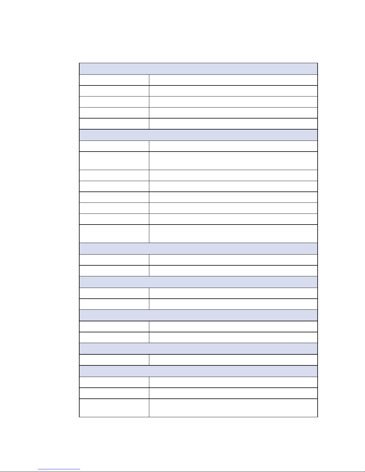
1.3.3 Specications of VIG-110M
System
Processor NXP i.MX6 UltraLite 696MHz Arm® Cortex®-A7 processor
Memory 1 DDR3L SDRAM, 512MB
Flash 1 NAND Flash, 512MB
EEPROM 1, up to 16KB
OS Debian Stretch R01-4.9.11
I/O Interface
Ethernet 2 10/100Mbps Ethernet, M12 connector
Serial 4 software configurable COM RS-232/422/485 (ESD 8KV) :
2 with RJ45 connector, 2 with DB9 connector
USB 1 USB 2.0 supports OTG (External)
GPIO 8 GPIO
Console 1 independent debug console
Reset Button 2 for H/W Reset and User Programming
LED 10 for System Ready, Power Status and User Programming
Antenna • 1 Antenna for NB-IoT
• 3 Antenna for WiFi/4G/LTE/GPRS/UMTS
Expansion
Mini PCIe 1 Full-size for USB/External SIM Card
SIM Card 1 SIM Card Socket (External)
Storage
MicroSD 1, supports SDHC, up to 128GB (External)
eMMC Optional, up to 32GB
Power
Power Input 6V to 40V, DC-in
Power Interface 3-pin Terminal Block : V+, V-, Frame Ground
Others
Watchdog Timer Reset : 0.5 to 128 sec./min. per step
Mechanical
Dimensions (W) 106mm x (L) 160mm x (H) 50mm (4.2" x 6.3" x 2.0")
Weight 0.6 kg (1.32 lb)
Mounting • DIN Rail Mount
• Wallmount by mounting bracket (Optional)
Page 12
6
GENERAL INTRODUCTION
©Vecow VIG-100 User Manual
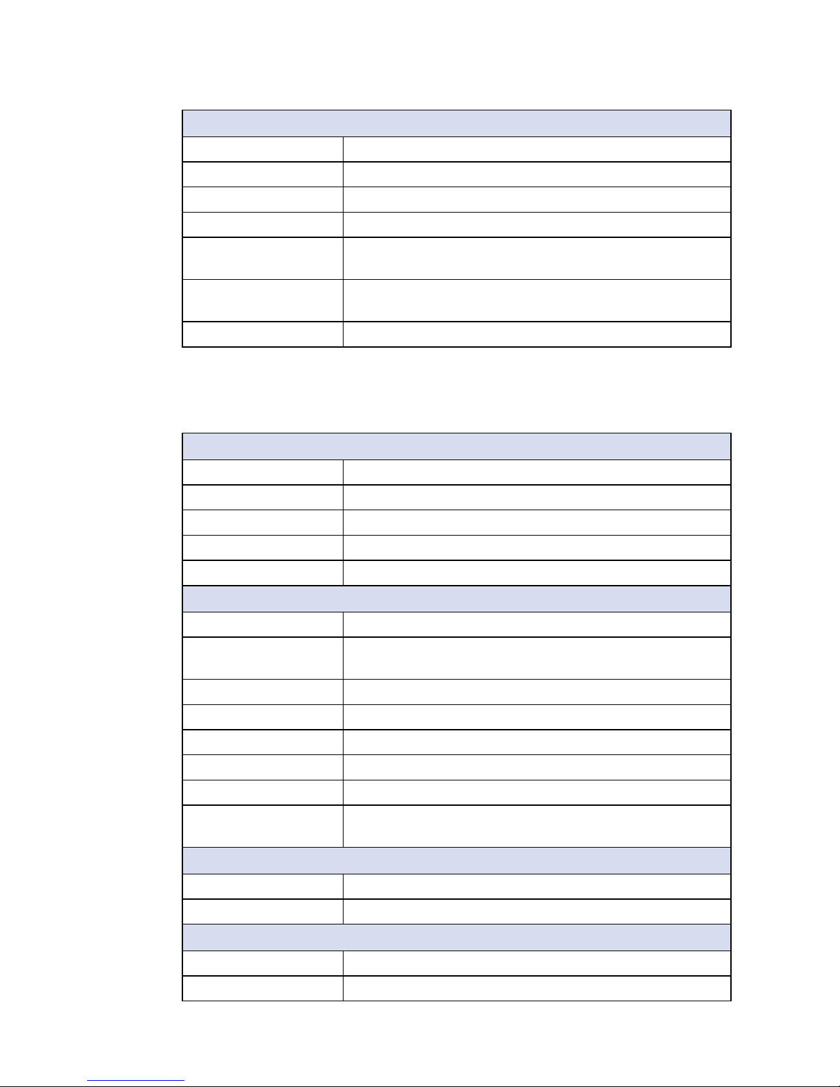
1.3.4 Specications of VIG-110
System
Processor NXP i.MX6 UltraLite 696MHz Arm® Cortex®-A7 processor
Memory 1 DDR3L SDRAM, 512MB
Flash 1 NAND Flash, 512MB
EEPROM 1, up to 16KB
OS Debian Stretch R01-4.9.11
I/O Interface
Ethernet 2 10/100Mbps Ethernet, RJ45 connector
Serial 4 software configurable COM RS-232/422/485 (ESD 8KV) :
2 with RJ45 connector, 2 with DB9 connector
USB 1 USB 2.0 supports OTG (External)
GPIO 8 GPIO
Console 1 independent debug console
Reset Button 2 for H/W Reset and User Programming
LED 10 for System Ready, Power Status and User Programming
Antenna • 1 Antenna for NB-IoT
• 3 Antenna for WiFi/4G/LTE/GPRS/UMTS
Expansion
Mini PCIe 1 Full-size for USB/External SIM Card
SIM Card 1 SIM Card Socket (External)
Storage
MicroSD 1, supports SDHC, up to 128GB (External)
eMMC Optional, up to 32GB
Environment
Operating Temperature -25°C to 70°C (-13°F to 158°F)
Storage Temperature -40°C to 85°C (-40°F to 185°F)
Humidity 5% to 95% Humidity, non-condensing
Relative Humidity 95% at 70°C
Shock • IEC 60068-2-27
• SSD : 50G @ Wallmount, Half-sine, 11ms
Vibration • IEC 60068-2-64
• SSD : 5Grms, 5Hz to 500Hz, 3 Axis
EMC CE, FCC, EN50155, EN50121-3-2
Page 13
7
GENERAL INTRODUCTION
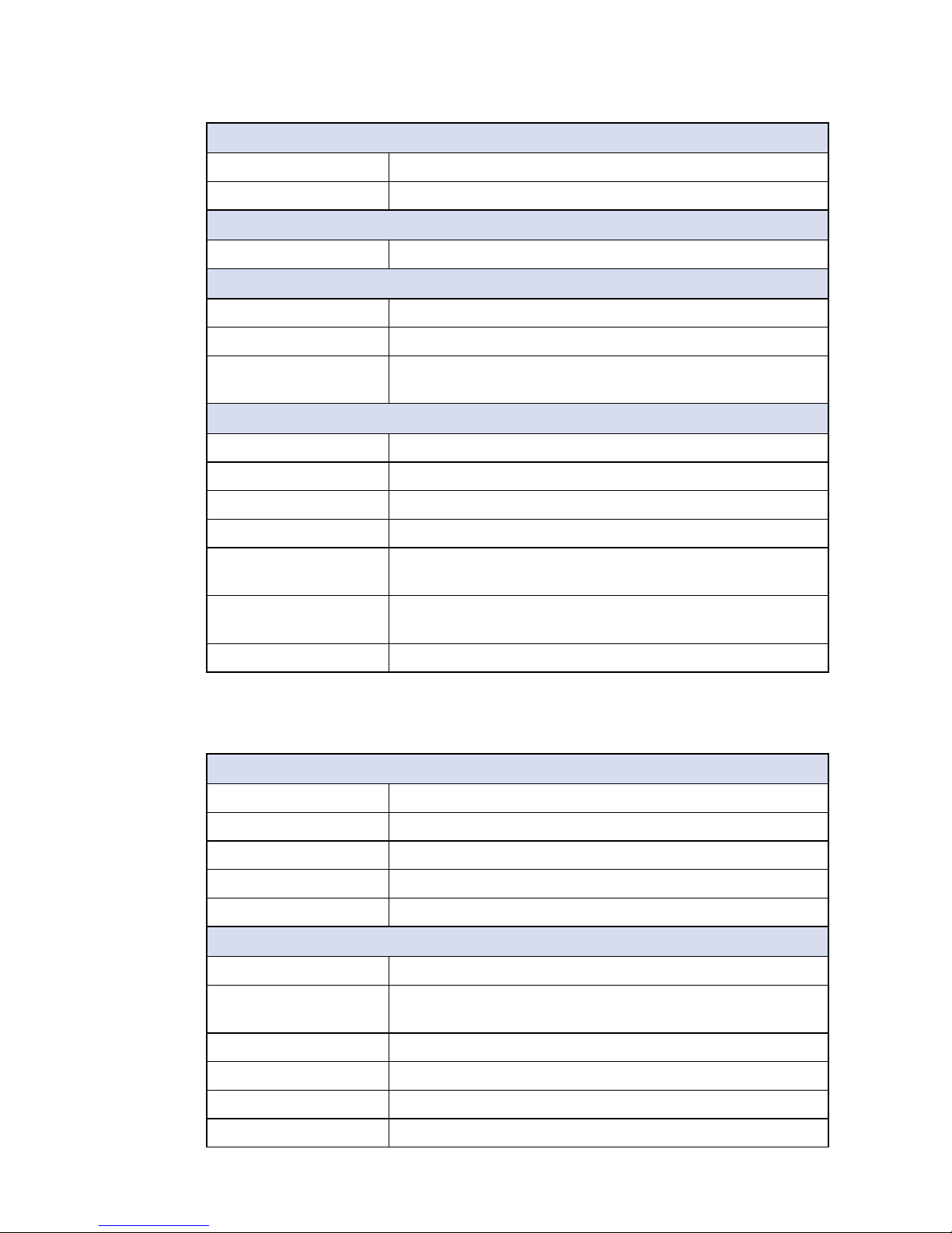
Power
Power Input 6V to 40V, DC-in
Power Interface 3-pin Terminal Block : V+, V-, Frame Ground
Others
Watchdog Timer Reset : 0.5 to 128 sec./min. per step
Mechanical
Dimensions (W) 106mm x (L) 160mm x (H) 50mm (4.2" x 6.3" x 2.0")
Weight 0.6 kg (1.32 lb)
Mounting • DIN Rail Mount
• Wallmount by mounting bracket (Optional)
Environment
Operating Temperature -25°C to 70°C (-13°F to 158°F)
Storage Temperature -40°C to 85°C (-40°F to 185°F)
Humidity 5% to 95% Humidity, non-condensing
Relative Humidity 95% at 70°C
Shock • IEC 60068-2-27
• SSD : 50G @ Wallmount, Half-sine, 11ms
Vibration • IEC 60068-2-64
• SSD : 5Grms, 5Hz to 500Hz, 3 Axis
EMC CE, FCC, EN50155, EN50121-3-2
1.3.5 Specications of VIG-100M
System
Processor NXP i.MX6 UltraLite 696MHz Arm® Cortex®-A7 processor
Memory 1 DDR3L SDRAM, 512MB
Flash 1 NAND Flash, 512MB
EEPROM 1, up to 16KB
OS Debian Stretch R01-4.9.11
I/O Interface
Ethernet 2 10/100Mbps Ethernet, M12 connector
Serial 2 software configurable COM RS-232/422/485with RJ45
connector (ESD 8KV)
USB 1 USB 2.0 supports OTG (External)
Console 1 independent debug console
Reset Button 2 for H/W Reset and User Programming
LED 10 for System Ready, Power Status and User Programming
Page 14
8
GENERAL INTRODUCTION
©Vecow VIG-100 User Manual
Antenna • 1 Antenna for NB-IoT
• 3 Antenna for WiFi/4G/LTE/GPRS/UMTS
Expansion
Mini PCIe 1 Full-size for USB/External SIM Card
SIM Card 1 SIM Card Socket (External)
Storage
MicroSD 1, supports SDHC, up to 128GB (External)
eMMC Optional, up to 32GB
Power
Power Input 6V to 40V, DC-in
Power Interface 3-pin Terminal Block : V+, V-, Frame Ground
Others
Watchdog Timer Reset : 0.5 to 128 sec./min. per step
Mechanical
Dimensions (W) 106mm x (L) 160mm x (H) 50mm (4.2" x 6.3" x 2.0")
Weight 0.6 kg (1.32 lb)
Mounting • DIN Rail Mount
• Wallmount by mounting bracket (Optional)
Environment
Operating Temperature -25°C to 70°C (-13°F to 158°F)
Storage Temperature -40°C to 85°C (-40°F to 185°F)
Humidity 5% to 95% Humidity, non-condensing
Relative Humidity 95% at 70°C
Shock • IEC 60068-2-27
• SSD : 50G @ Wallmount, Half-sine, 11ms
Vibration • IEC 60068-2-64
• SSD : 5Grms, 5Hz to 500Hz, 3 Axis
EMC CE, FCC, EN50155, EN50121-3-2
1.3.6 Specications of VIG-100
System
Processor NXP i.MX6 UltraLite 696MHz Arm® Cortex®-A7 processor
Memory 1 DDR3L SDRAM, 512MB
Flash 1 NAND Flash, 512MB
EEPROM 1, up to 16KB
OS Debian Stretch R01-4.9.11
Page 15

9
GENERAL INTRODUCTION
I/O Interface
Ethernet 2 10/100Mbps Ethernet, RJ45 connector
Serial 2 software configurable COM RS-232/422/485with RJ45
connector (ESD 8KV)
USB 1 USB 2.0 supports OTG (External)
Console 1 independent debug console
Reset Button 2 for H/W Reset and User Programming
LED 10 for System Ready, Power Status and User Programming
Antenna • 1 Antenna for NB-IoT
• 3 Antenna for WiFi/4G/LTE/GPRS/UMTS
Expansion
Mini PCIe 1 Full-size for USB/External SIM Card
SIM Card 1 SIM Card Socket (External)
Storage
MicroSD 1, supports SDHC, up to 128GB (External)
eMMC Optional, up to 32GB
Power
Power Input 6V to 40V, DC-in
Power Interface 3-pin Terminal Block : V+, V-, Frame Ground
Others
Watchdog Timer Reset : 0.5 to 128 sec./min. per step
Mechanical
Dimensions (W) 106mm x (L) 160mm x (H) 50mm (4.2" x 6.3" x 2.0")
Weight 0.6 kg (1.32 lb)
Mounting • DIN Rail Mount
• Wallmount by mounting bracket (Optional)
Environment
Operating Temperature -25°C to 70°C (-13°F to 158°F)
Storage Temperature -40°C to 85°C (-40°F to 185°F)
Humidity 5% to 95% Humidity, non-condensing
Relative Humidity 95% at 70°C
Shock • IEC 60068-2-27
• SSD : 50G @ Wallmount, Half-sine, 11ms
Vibration • IEC 60068-2-64
• SSD : 5Grms, 5Hz to 500Hz, 3 Axis
EMC CE, FCC, EN50155, EN50121-3-2
Page 16
10
GENERAL INTRODUCTION
©Vecow VIG-100 User Manual
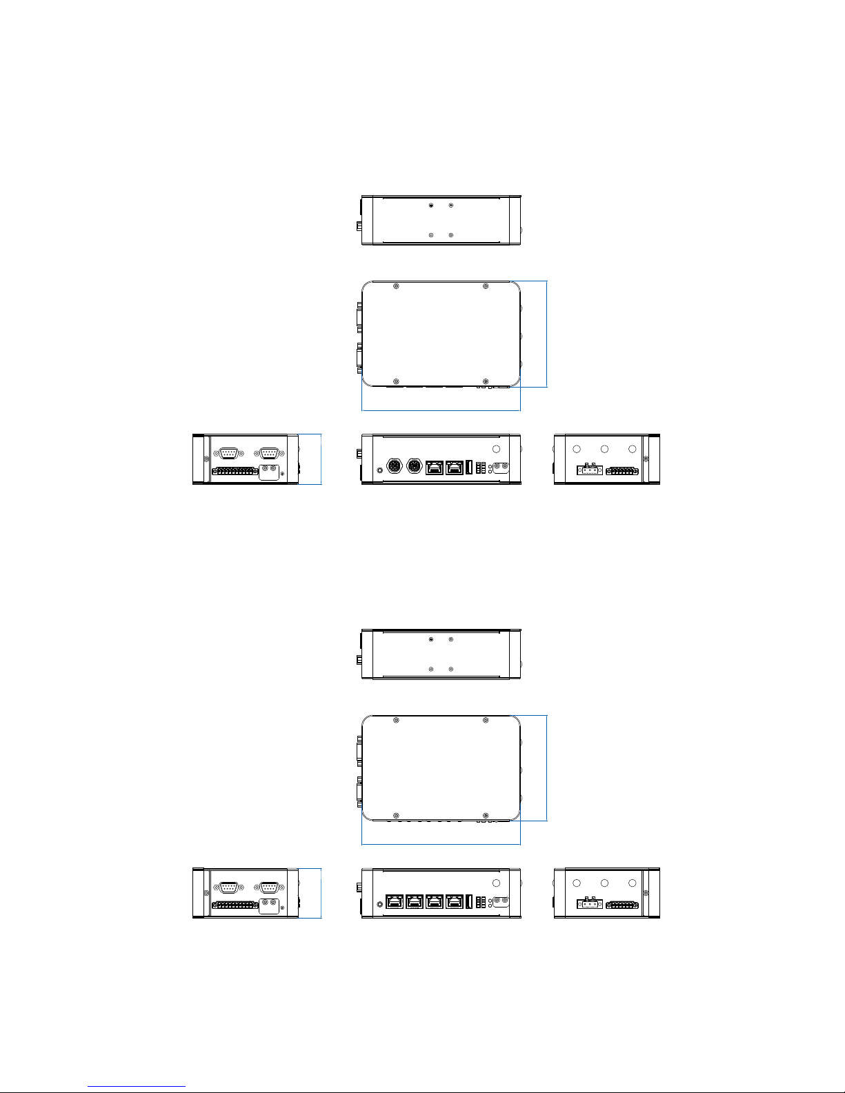
1.4 Mechanical Dimension
1.4.1 Dimensions of VIG-120M
106.0 (4.17”)
50.0 (1.97”)
159.5 (6.28”)
Unit: mm (inch)
1.4.2 Dimensions of VIG-120
106.0 (4.17”)
50.0 (1.97”)
159.5 (6.28”)
Unit: mm (inch)
Page 17
11
GENERAL INTRODUCTION
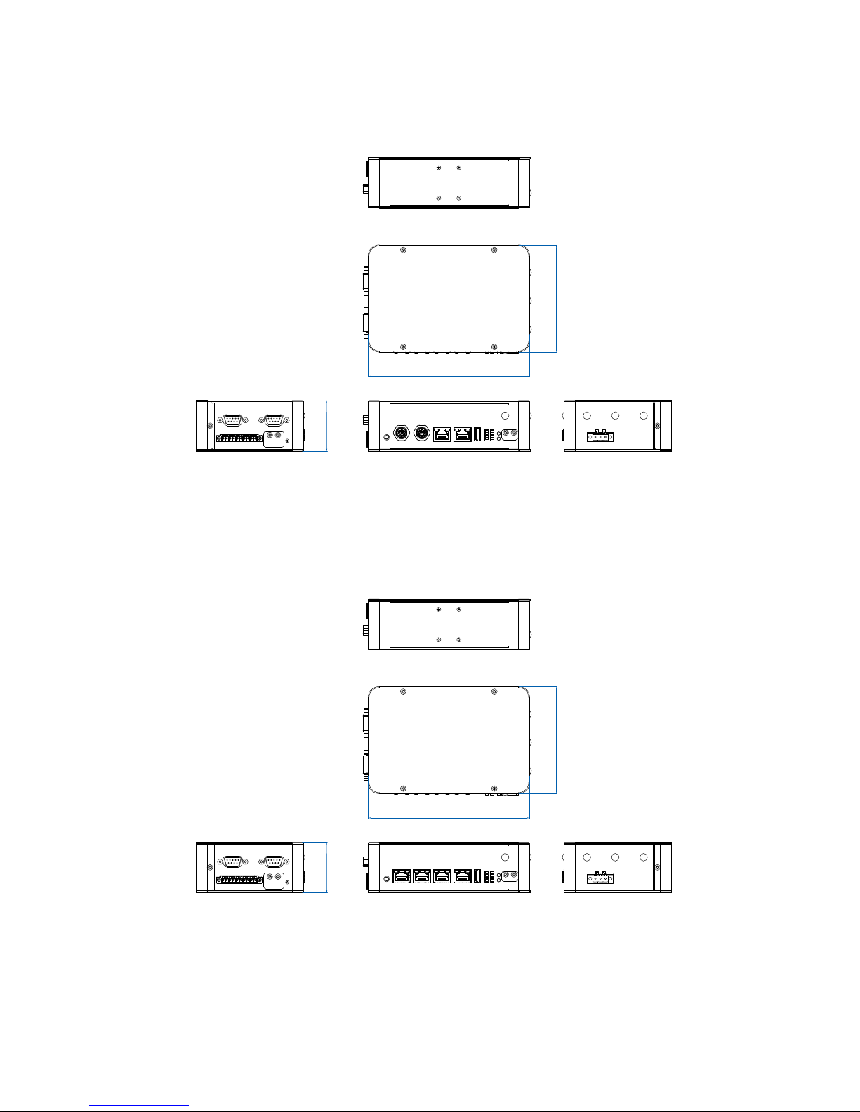
1.4.3 Dimensions of VIG-110M
106.0 (4.17”)
50.0 (1.97”)
159.5 (6.28”)
Unit: mm (inch)
1.4.4 Dimensions of VIG-110
106.0 (4.17”)
50.0 (1.97”)
159.5 (6.28”)
Unit: mm (inch)
Page 18
12
GENERAL INTRODUCTION
©Vecow VIG-100 User Manual
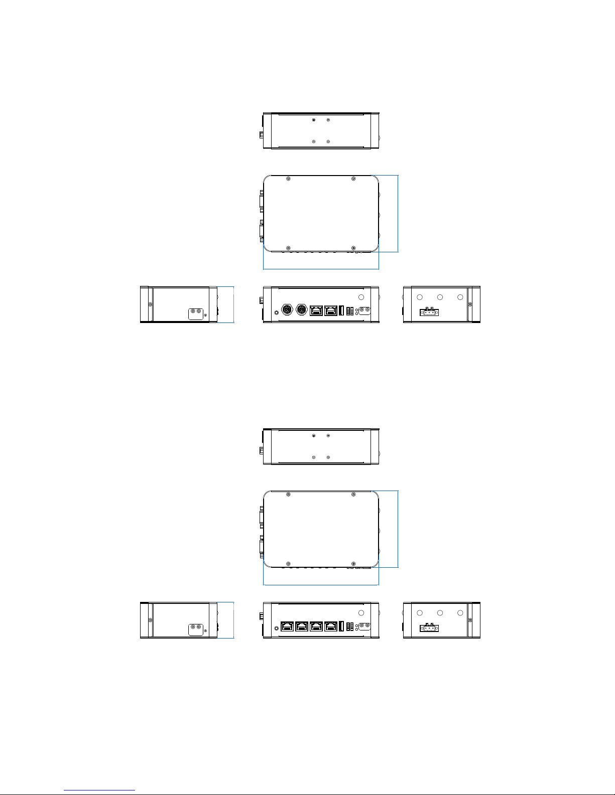
1.4.5 Dimensions of VIG-100M
106.0 (4.17”)
50.0 (1.97”)
159.5 (6.28”)
Unit: mm (inch)
1.4.6 Dimensions of VIG-100
106.0 (4.17”)
50.0 (1.97”)
159.5 (6.28”)
Unit: mm (inch)
Page 19
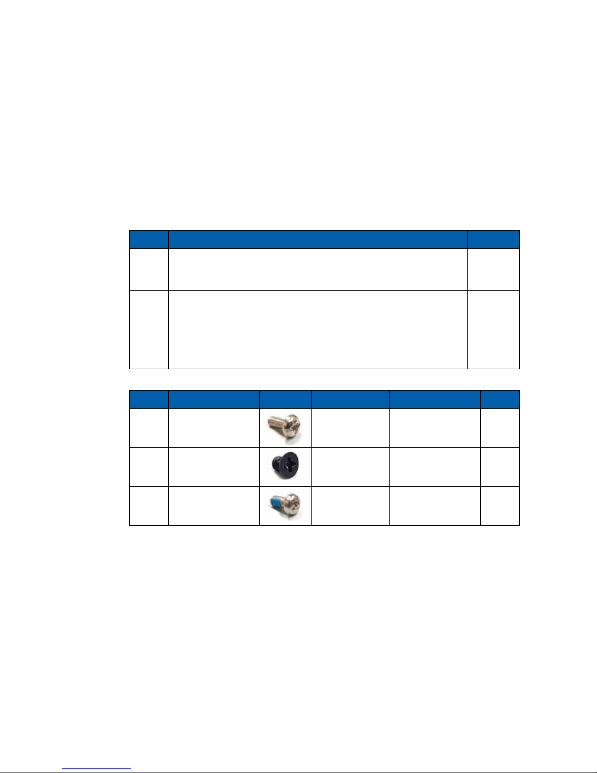
13
GETTING TO KNOW YOUR VIG-100
2
GETTING TO KNOW YOUR VIG-100
2.1 Packing List
Item Description Qty
1 VIG-100 Industrial-grade Wireless IoT Gateway (According
to the conguration of you order, VIG-100 series may contain
MicroSD. Please verify these items if necessary.)
1
2 VIG-100 series accessory box, which contains
● Vecow Drivers & Utilities DVD
● Wall-mounting bracket (PN : 62-01P0071-000)
● 3-pin pluggable terminal block
● 10-pin pluggable terminal block
● 6-pin pluggable terminal block
1
1
1
1
1
Item Description Picture Use For P/N Qty
1
P Head Screw
M2.5X6L mm
Mini PCIe Slot 53-2426906-30B 1
2
F Head Screw
M3X4L mm
Wall Mount
Bracket
53-2470000-218 4
3
P Head Screw
M3X6L mm
NB-IOT 53-2426206-80B 1
Page 20
14
GETTING TO KNOW YOUR VIG-100©Vecow VIG-100 User Manual
2.2 Front Panel I/O & Functions
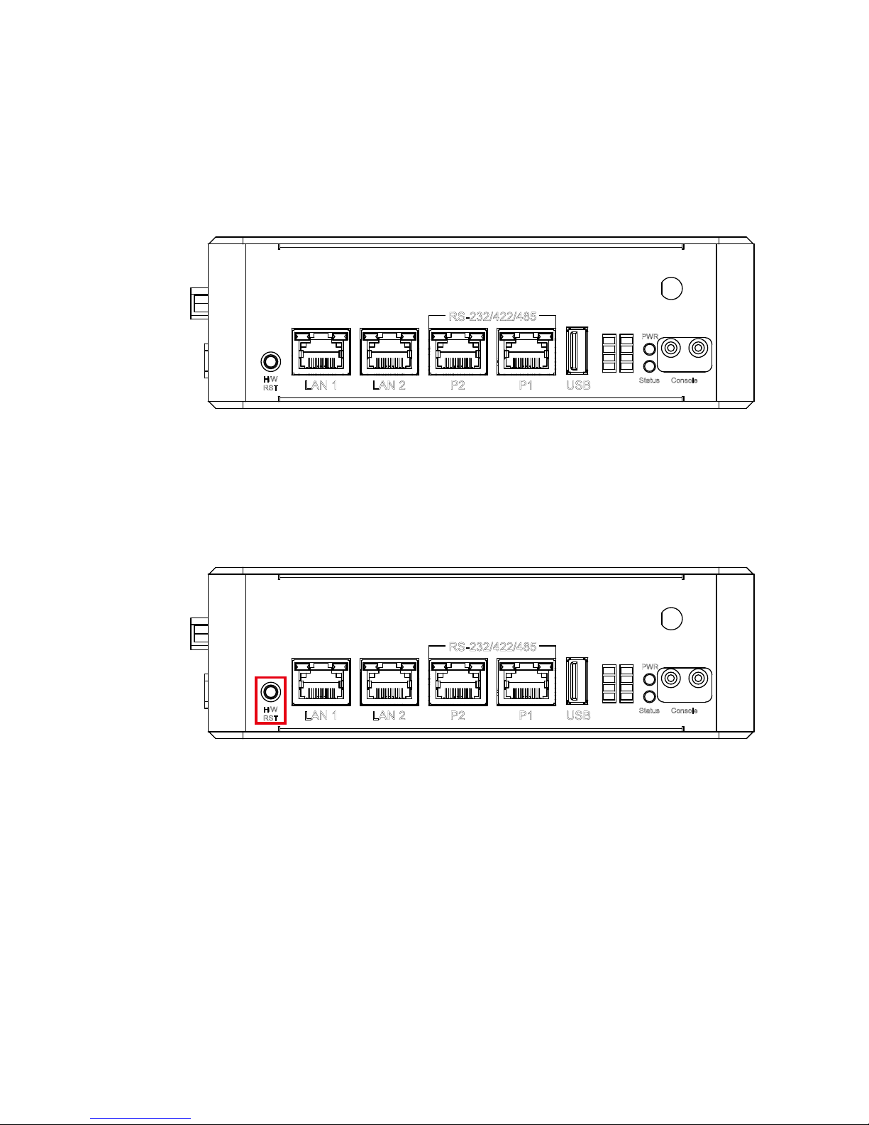
In Vecow VIG-100 series, there are 3 sides of the I/O connectors which
located on the front, top and bottom panels. Most of the general connections to
computer devices, such as USB, COM (RJ-45 Connector), LAN, Console port,
Reset button and LED indicators are placed on the front panel.
1
2
3
4
5
6
7
8
PWR
H/W
RST
Status
LAN 1 LAN 2 P2 P1 USB
Console
RS-232/422/485
2.2.1 H/W Reset Button
1
2
3
4
5
6
7
8
PWR
H/W
RST
Status
LAN 1 LAN 2 P2 P1 USB
Console
RS-232/422/485
To boot up the system, please press H/W Reset button in 2 seconds. To shut
down the system, please press the button in 7 seconds. If system error, you can
just press the H/W Reset button to restart.
Page 21
15
GETTING TO KNOW YOUR VIG-100
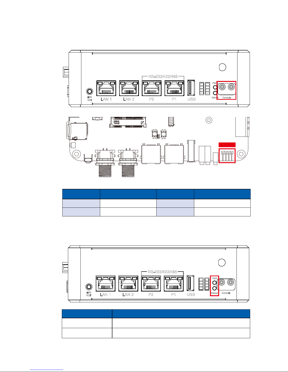
2.2.2 Console Port
1
2
3
4
5
6
7
8
PWR
H/W
RST
Status
LAN 1 LAN 2 P2 P1 USB
Console
RS-232/422/485
Pin 4 3 2 1
Pin No. Function Pin No. Function
1 +V5 3 USB_DATA+
2 USB_DATA- 4 GND
Console Port Pin Out :
2.2.3 PWR & Status LED Indicators
LED Color System Status
Green (PWR LED) +V3.3 Power Ready
Yellow (Status LED) System Running
1
2
3
4
5
6
7
8
PWR
H/W
RST
Status
LAN 1 LAN 2 P2 P1 USB
Console
RS-232/422/485
Page 22
16
GETTING TO KNOW YOUR VIG-100©Vecow VIG-100 User Manual
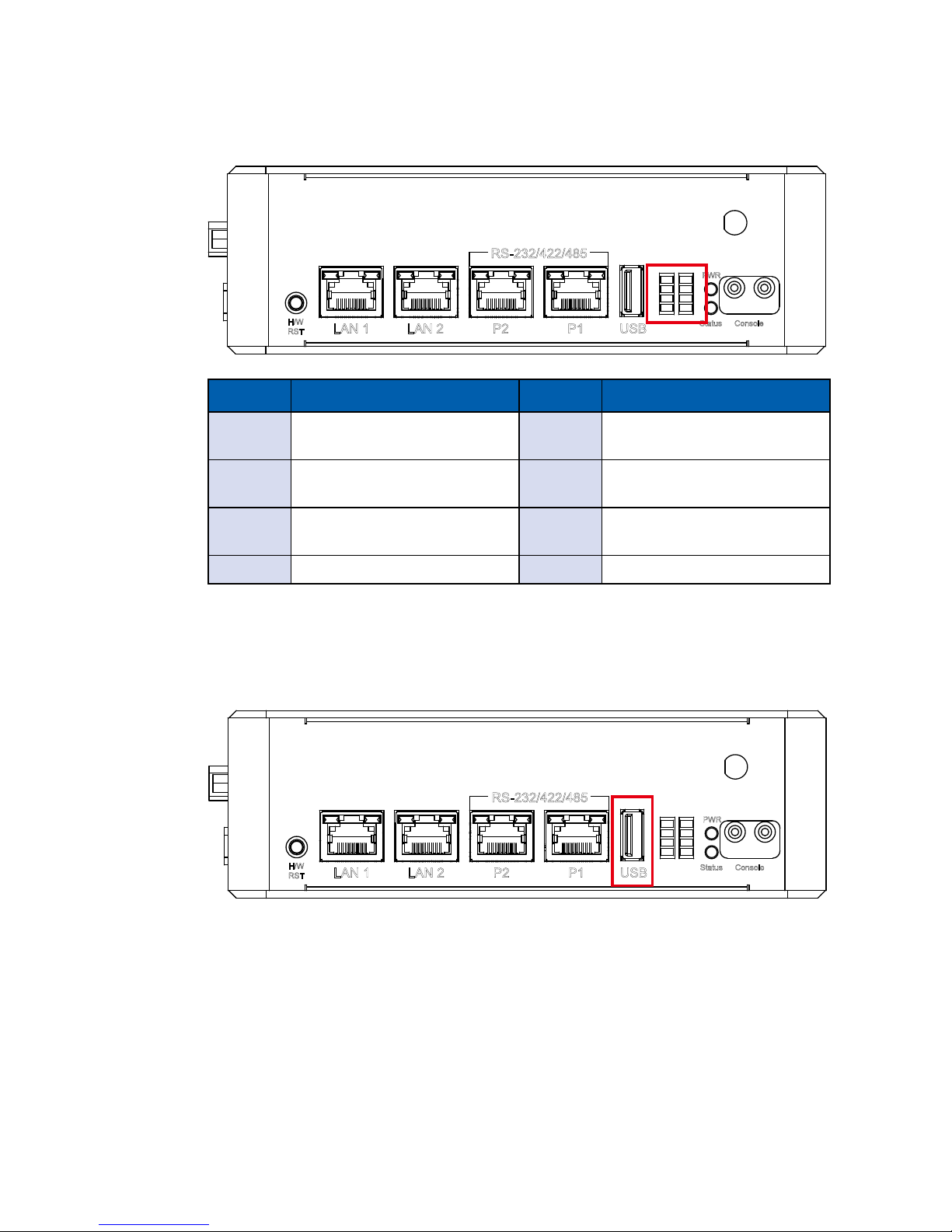
2.2.4 Programmable LED Indicators
1
2
3
4
5
6
7
8
PWR
H/W
RST
Status
LAN 1 LAN 2 P2 P1 USB
Console
RS-232/422/485
LED No. LED Status LED No. LED Status
1
P3 (COM3)
TX Transport Blinking
5
P4 (COM4)
TX Transport Blinking
2
CAN 1
TX Transport Blinking
6 CAN 2
TX Transport Blinking
3
Mini PCIe Slot
USB Detect LED
7 MicroSD Card
Detect LED
4 Programmable LED 8 Programmable LED
2.2.5 USB 2.0
1
2
3
4
5
6
7
8
PWR
H/W
RST
Status
LAN 1 LAN 2 P2 P1 USB
Console
RS-232/422/485
This USB interface supports 480 Mbps transfer rate complied with high speed
USB specification Rev. 2.0. Also, the USB supports OTG mode and default
setting as HOST mode.
Page 23
17
GETTING TO KNOW YOUR VIG-100
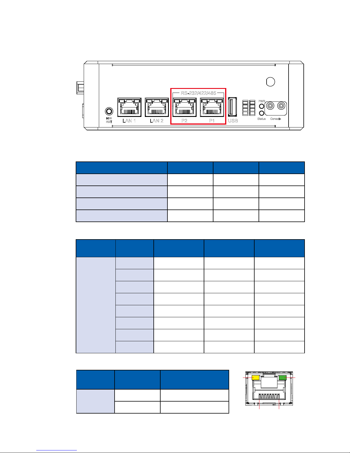
2.2.6 COM Port (RJ45 connector)
1
2
3
4
5
6
7
8
PWR
H/W
RST
Status
LAN 1 LAN 2 P2 P1 USB
Console
RS-232/422/485
These Serial ports (P1~2) can be congured for RS-232, RS-422, or RS-485.
Mode Mode2 Mode1 Mode0
Loop Back Low Low Low
RS-232 Low Low High
RS-422 (5-Wire) Low High High
RS-485 Low High Low
P1 & P2 Mode Conguration Table:
RJ-45
Connector
Pin No. RS-232 RS-422
(5-wire)
RS-485
(3-wire)
P1/P2
1 Reserved ----------- -----------
2 RTS ----------- -----------
3 GND GND GND
4 TXD RXD+ -----------
5 RXD TXD+ DATA+
6 DCD TXD- DATA-
7 CTS ----------- -----------
8 DTR RXD- -----------
P1 & P2 RS-232/RS-422/RS-485 Pin Out:
P1 & P2 LED Table:
RJ-45
Connector
LED Color LED Status
P1/P2
Yellow RX Receive Blinking
Green TX Transport Blinking
18
RX
LED
TX
LED
Page 24
18
GETTING TO KNOW YOUR VIG-100©Vecow VIG-100 User Manual
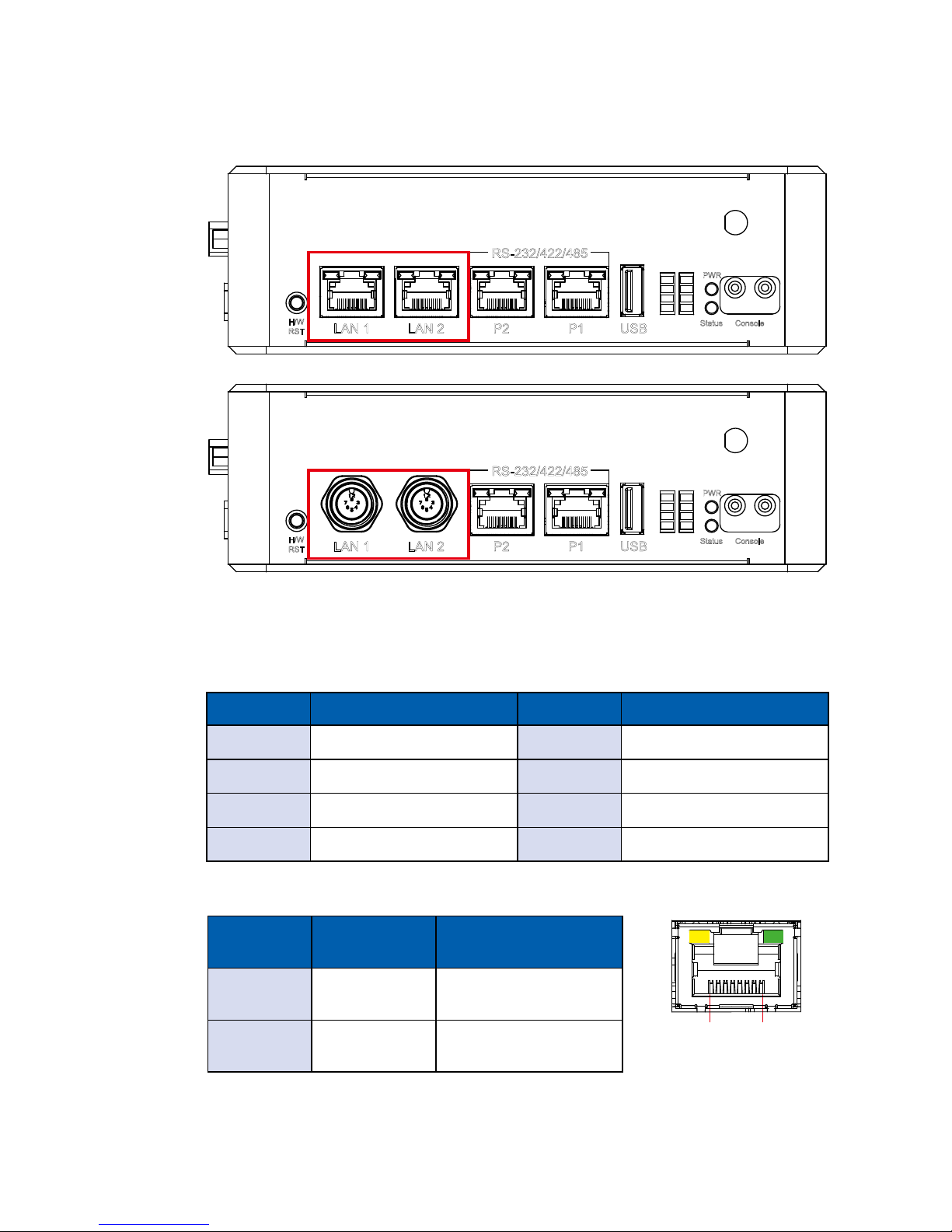
2.2.7 10/100 Mbps Ethernet Port
There are two Ethernet ports auto-sensing 10/100 Mbps in RJ45 or M12
connectors on the front side of VIG-100 series.
1
2
3
4
5
6
7
8
PWR
H/W
RST
Status
LAN 1 LAN 2 P2 P1 USB
Console
RS-232/422/485
1
2
3
4
5
6
7
8
PWR
H/W
RST
Status
LAN 1 LAN 2 P2 P1 USB
Console
RS-232/422/485
LAN 1 & 2 Pin Out :
Pin No. 10/100 Mbps Pin No. 10/100 Mbps
1 E_TX+ 5 ----
2 E_TX- 6 E_RX-
3 E_RX+ 7 -----
4 ---- 8 -----
LAN 1 & 2 LED Table:
RJ-45
LED
10Mbps 100Mbps
Right LED
Green
Off Solid Green
Left LED
Yellow
Flash Yellow Flash Yellow
18
Page 25
19
GETTING TO KNOW YOUR VIG-100
2.3 Top Panel I/O & Functions
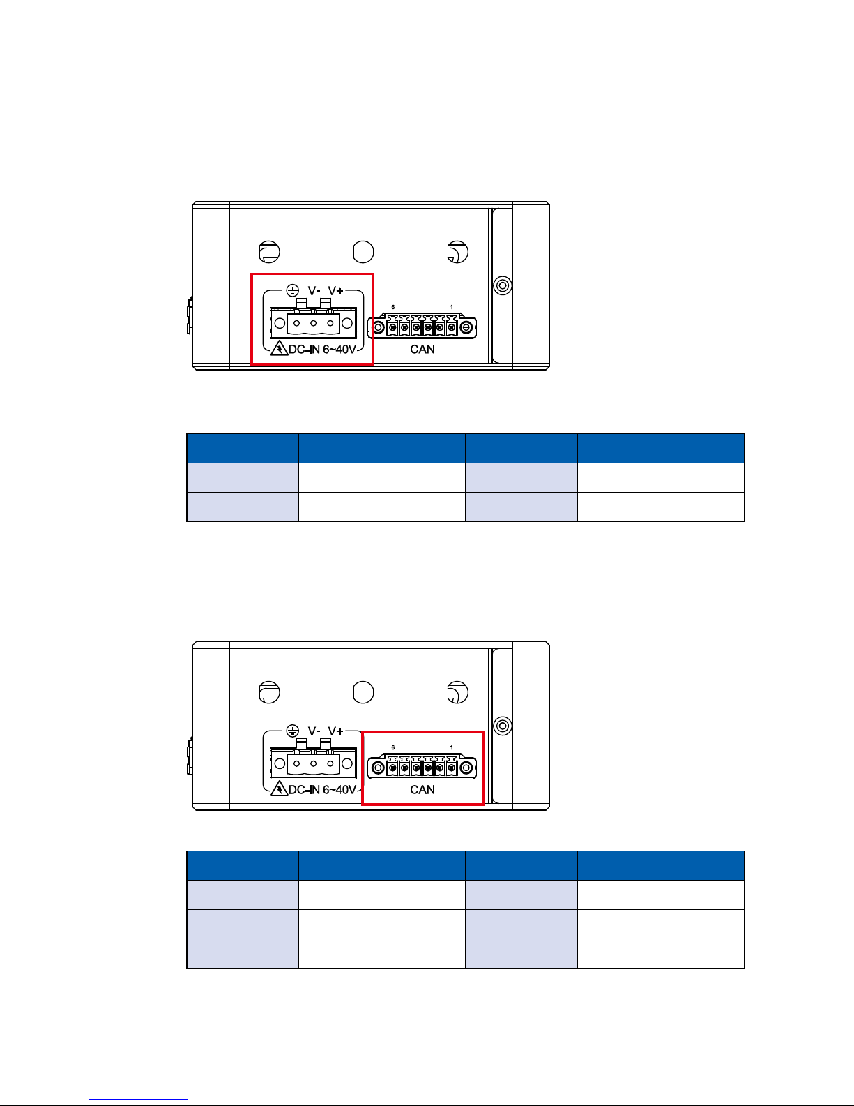
2.3.1 Power Terminal Block
VIG-100 supports 6V to 40V DC wide range power input by terminal block on
the top side. Besides, onboard LTC4364 supports up to 80V surge protection.
Pin No. Description Pin No. Description
1 V+ 3 Chassis Ground
2 V-
2.3.2 CAN Bus Port
CAN Bus Connector Pin Out:
Pin No. Description Pin No. Description
1 GND 4 GND
2 CANL1 5 CANL2
3 CANH1 6 CANH2
Page 26
20
GETTING TO KNOW YOUR VIG-100©Vecow VIG-100 User Manual
2.4 Bottom Panel I/O & Functions
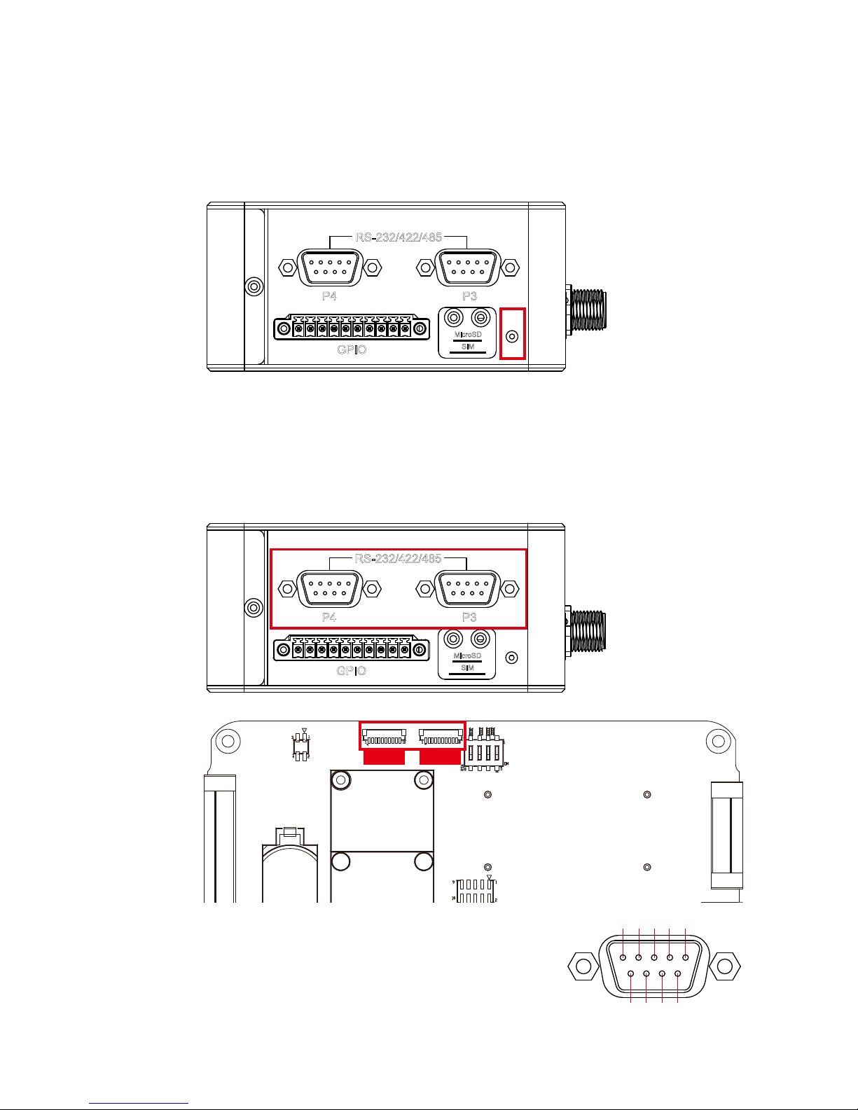
2.4.1 Programmable Reset Button
SIM
MicroSD
GPIO
10 1
P4 P3
RS-232/422/485
VIG-100 is also equipped with a Programmable Button for users’ easy maintenance.
2.4.2 COM Port (DB9 connector)
SIM
MicroSD
GPIO
10 1
P4 P3
RS-232/422/485
CN1 (P4) CN2 (P3)
The same as P1~2 on the front panel, Serial port
P3~4 can also be congured for RS-232, RS-422,
or RS-485 with auto ow control communications.
6 7 8 9
54321
Page 27
21
GETTING TO KNOW YOUR VIG-100
Mode Mode2 Mode1 Mode0
Loop Back Low Low Low
RS-232 Low Low High
RS-422 (5-Wire) Low High High
RS-485 Low High Low
P3 & P4 Mode Conguration Table:
DB9
Connector
Pin No. RS-232 RS-422
(5-wire)
RS-485
(3-wire)
P3/P4
1 DCD TXD- DATA-
2 RXD TXD+ DATA+
3 TXD RXD+ -----------
4 DTR RXD- -----------
5 GND GND GND
6 ----------- ----------- -----------
7 RTS ----------- -----------
8 CTS ----------- -----------
P3 & P4 RS-232/RS-422/RS-485 Pin Out:
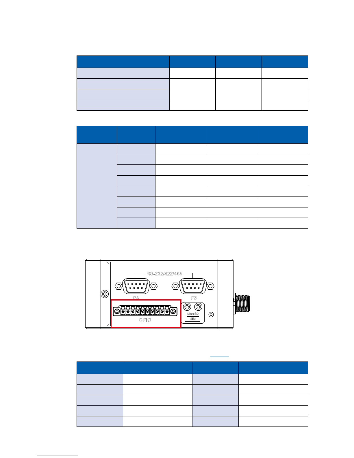
2.4.3 GPIO
SIM
MicroSD
GPIO
10 1
P4 P3
RS-232/422/485
In VIG-100 series, it is offered with eight programmable I/O within TTL 3.3V
tolerance. If the GPIO is logic high, it indicates the accurate signal mapping on
SIO GPIO pin and vice versa. (Please refer to CH2.7 for detailed information.)
Pin No. Description Pin No. Description
1 +V3.3 6 GPIO5
2 GPIO1 7 GPIO6
3 GPIO2 8 GPIO7
4 GPIO3 9 GPIO8
5 GPIO4 10 GND
Page 28
22
GETTING TO KNOW YOUR VIG-100©Vecow VIG-100 User Manual
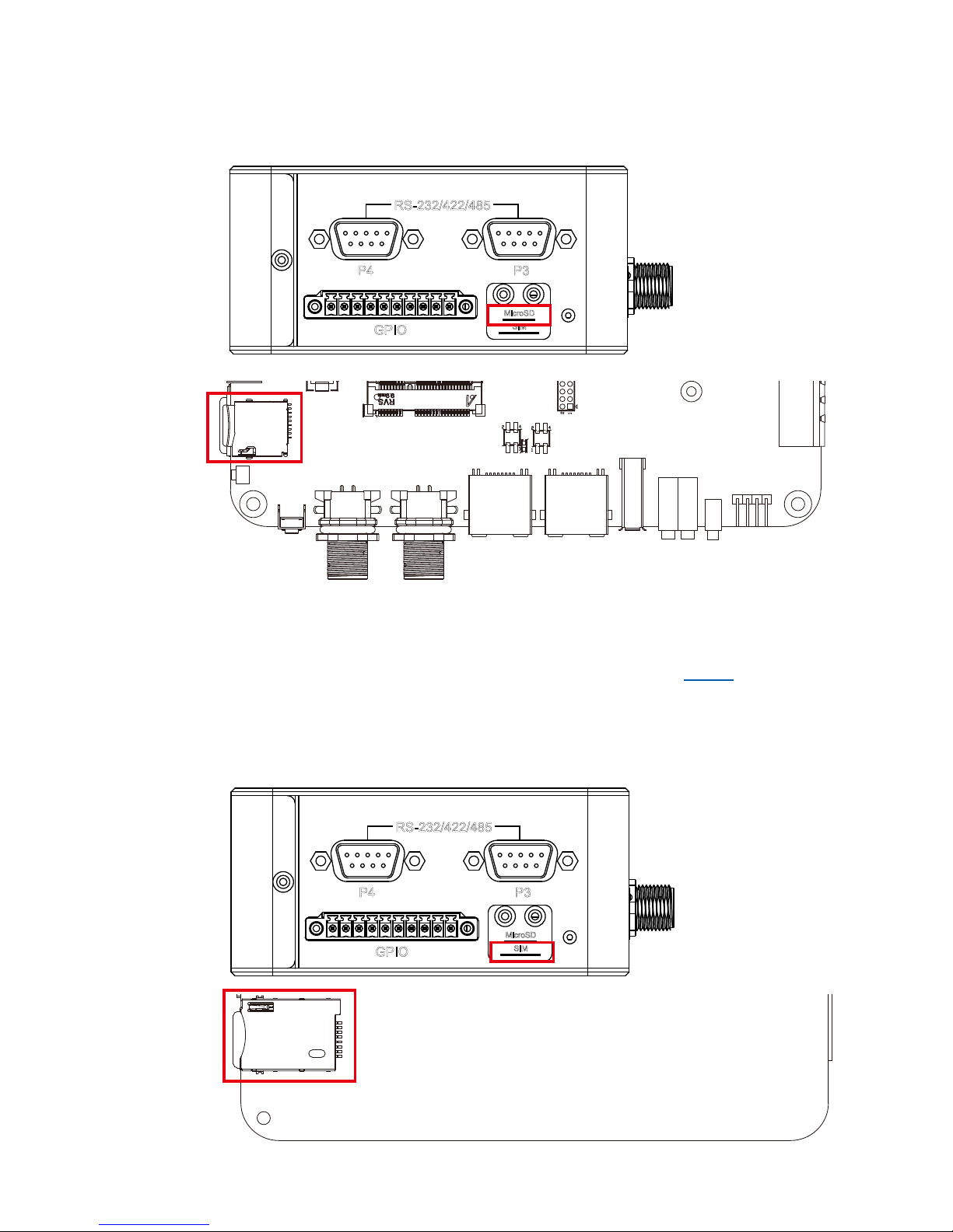
2.4.4 MicroSD Card
SIM
MicroSD
GPIO
10 1
P4 P3
RS-232/422/485
The external MicroSD card provides additional storage expansion. It is located
behind the cover-plate on the bottom panel. If you would like to replace or insert
the card, you MUST ensure the system is powered off, loosen the screws, take
out the cover-plate, and then access the slot. (Please refer to CH3.2 for detailed
information.)
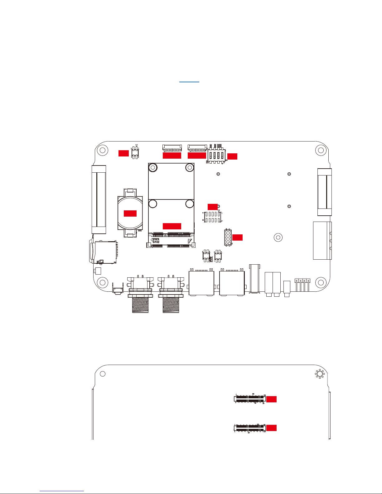
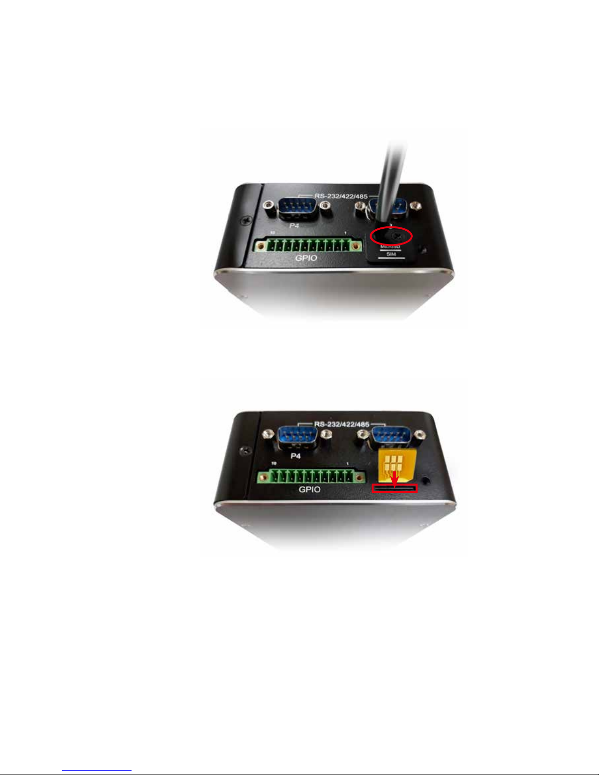
2.4.5 SIM Card
SIM
MicroSD
GPIO
10 1
P4 P3
RS-232/422/485
Page 29
23
GETTING TO KNOW YOUR VIG-100
The external SIM card offers wireless communication capability to the system.
It’s also located behind the cover-plate and under the MicroSD slot. If you
would like to replace or insert the card, please take the same actions as treating
MicroSD card. (Please refer to CH3.6 for detailed information.)
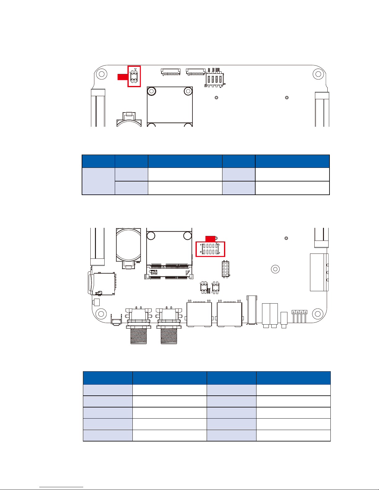
2.5 Main Board Expansion Connectors
2.5.1 Top View of VIG-100 Main Board with Connector Locations
CN5
CN6
SW1
J1
CN1 (P4) CN2 (P3)
MPCIe1
BAT 1
2.5.2 Bottom View of VIG-100 Main Board with Connector Locations
J6
J7
Page 30
24
GETTING TO KNOW YOUR VIG-100©Vecow VIG-100 User Manual
2.5.3 J1 : I2C Header
J1
VIG-100 is also equipped with an I2C header.
I2C Header Pin Out:
Pin No. Denition Pin No. Denition
J1
1 GND 3 +V3.3
2 I2C2_SDA 4 I2C2_SCL
There are 2 audio headers, Mic-in and Line-out, in VIG-100 series.
Audio Header Pin Out:
2.5.4 CN5 : Audio Header
CN5
Pin No. Description Pin No. Description
1 MIC-L 2 A_GND
3 MIC-R 4 GND
5 LINEO-R 6 ------
7 ------ 8 GND
9 LINEO-L 10 ------
Page 31
25
GETTING TO KNOW YOUR VIG-100
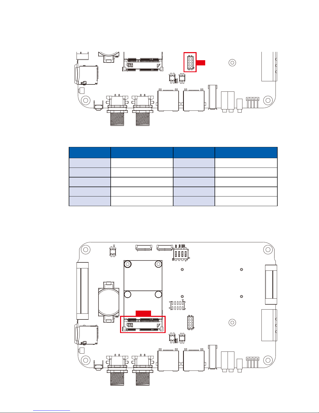
2.5.5 CN6 : NB-IoT Module Header
CN6
There is a NB-IoT module header in VIG-100.
NB-IoT Header Pin Out:
Pin No. Description Pin No. Description
1 ------ 2 NB-IOT-TX
3 ------ 4 NB-IOT-RX
5 ------ 6 NB-IOT-RTS
7 GND 8 NB-IOT-CTS
9 GND 10 +V3.3
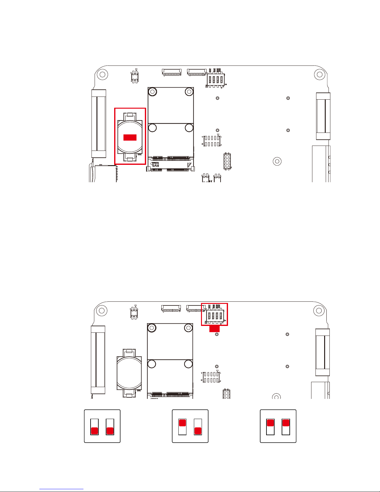
2.5.6 MPCIE1 : Mini PCIe Slot
MPCIe1
Page 32

26
GETTING TO KNOW YOUR VIG-100©Vecow VIG-100 User Manual
There is a Mini PCIe supported with USB signal in VIG-100.
Mini PCIe Pin Out:
Pin No. function Pin No. function
51 Reserved 52 +V3.3
49 Reserved 50 GND
47 Reserved 48 +1.5V
45 Reserved 46 Reserved
43 Reserved 44 Reserved
41 +V3.3 42 Reserved
39 +V3.3 40 GND
37 GND 38 USB_D+
35 GND 36 USB_D-
33 Reserved 34 GND
31 Reserved 32 SMB_DATA
29 GND 30 SMB_CLK
27 GND 28 +1.5V
25 Reserved 26 GND
23 Reserved 24 +V3.3
21 GND 22 Reserved
19 Reserved 20 Reserved
17 Reserved 18 GND
Mechanical Key
15 GND 16 Reserved
13 Reserved 14 Reserved
11 Reserved 12 Reserved
9 GND 10 Reserved
7 Reserved 8 Reserved
5 Reserved 6 1.5V
3 Reserved 4 GND
1 Reserved 2 +V3.3
Page 33
27
GETTING TO KNOW YOUR VIG-100
2.5.7 BAT1 : RTC Battery
BAT 1
VIG-100 real-time clock is powered by a lithium battery. It is equipped with
Panasonic BR2032 190mAh lithium battery. It is recommended that you not
replace the lithium battery on your own. If the battery needs to be changed,
please contact Vecow RMA service team.
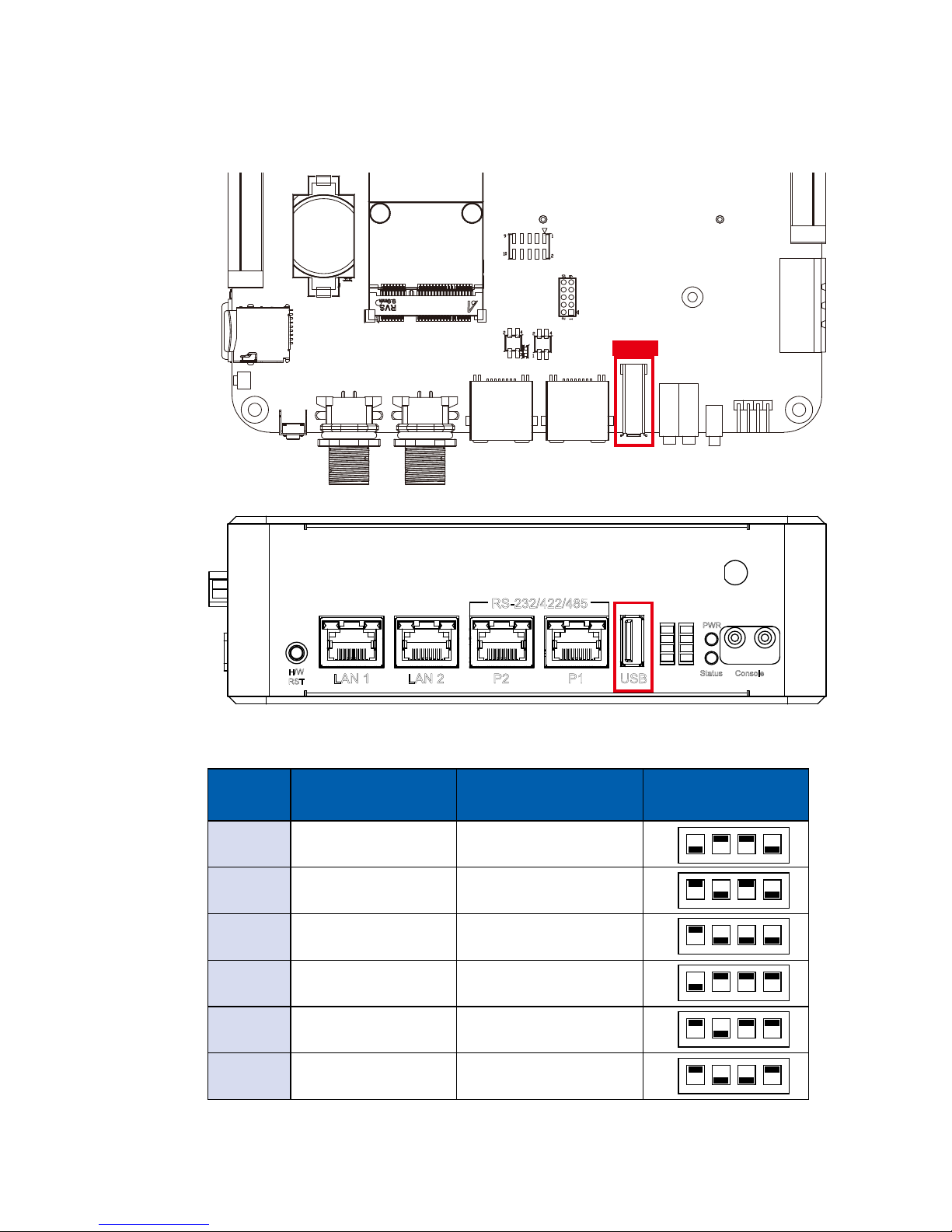
2.6 Main Board Jumper & Deep Switch Settings
2.6.1 Top View of VIG-100 with Jumper and DIP Switch
SW1
1 : ON
2 : OFF
ON
12
1 : OFF
2 : OFF
ON
12
1 : ON
2 : ON
ON
12
Page 34
28
GETTING TO KNOW YOUR VIG-100©Vecow VIG-100 User Manual
1
2
3
4
5
6
7
8
PWR
H/W
RST
Status
LAN 1 LAN 2 P2 P1 USB
Console
RS-232/422/485
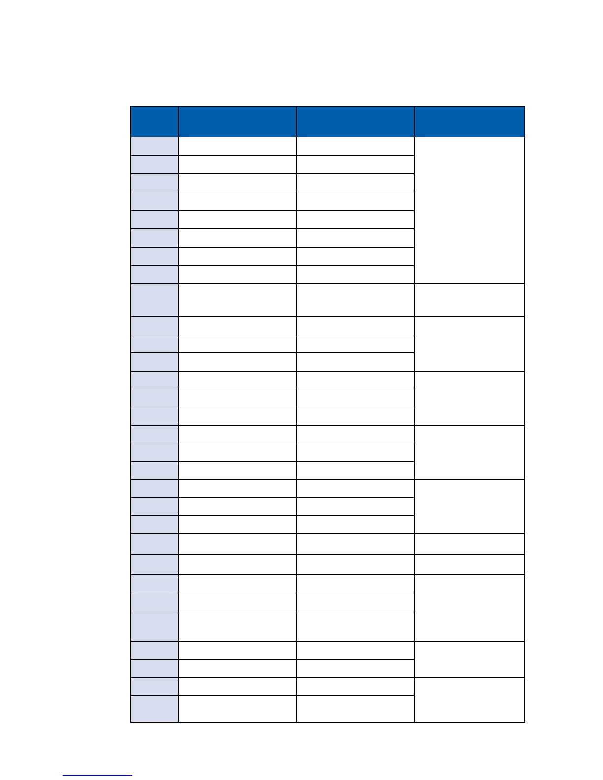
There are a SW1 of boot strap mode and USB2.0 power on/off in VIG-100.
Item Boot strap
USB2.0 (Right angle)
5V Power
Switch Position
1 NAND Mode USB Power Off
2 eMMC Mode USB Power Off
3 SD Card Mode USB Power Off
4 NAND Mode USB Power ON
5 eMMC Mode USB Power ON
6 SD Card Mode USB Power ON
ON
1 2 3 4
ON
1 2 3 4
ON
1 2 3 4
ON
1 2 3 4
ON
1 2 3 4
ON
1 2 3 4
USB 2.0
2.6.2 SW1 : Boot Strap & USB2.0 Right angle +V5 Power(on/o)
Page 35
29
GETTING TO KNOW YOUR VIG-100
Item
SOM Module GPIO
Denition
VIG-100 GPIO
Denition
Function
1 GPIO 3_0 GPIO1
GPIO Connector
2 GPIO 5_5 GPIO2
3 GPIO 5_3 GPIO3
4 GPIO 4_24 GPIO4
5 GPIO 3_3 GPIO5
6 GPIO 3_2 GPIO6
7 GPIO 3_4 GPIO7
8 GPIO 4_18 GPIO8
9 GPIO 5_1 Programmable Button
Programmable Reset
Button
10 GPIO 3_28 P1_MODE0
P1 Mode11 GPIO 3_7 P1_MODE1
12 GPIO 3_27 P1_MODE2
13 GPIO 3_23 P2_MODE0
P2 Mode14 GPIO 3_19 P2_MODE1
15 GPIO 3_17 P2_MODE2
16 GPIO 3_24 P3_MODE0
P3 Mode17 GPIO 3_20 P3_MODE1
18 GPIO 3_6 P3_MODE2
19 GPIO 3_8 P4_MODE0
P4 Mode20 GPIO 3_5 P4_MODE1
21 GPIO 5_10 P4_MODE2
22 GPIO 1_8 Watch dog Watch dog
23 GPIO 1_0 USB_OTG USB2.0 OTG
24 GPIO 5_7 Programmable LED(4)
Programmable LED
25 GPIO 5_8 Programmable LED(8)
26 GPIO 5_9
MPCIE1 Slot USB
Detect LED
27 I2C1_SDA I2C1_SDA
Board ID
Address 1010 000x
28 I2C1_SCL I2C1_SCL
29 I2C2_SDA I2C2_SDA
I2C RTC Real time
clock/Calendar
Address 1101 000x
30 I2C2_ SCL I2C2_ SCL
2.7 GPIO Pin Assignments Table
Page 36

30
HARDWARE INSTALLATION©Vecow VIG-100 User Manual
3
Step 1
Step 2
SYSTEM SETUP
3.1 How to Open Your VIG-100
Loosen screws on top cover marked with "VECOW logo."
Open the Top cover.
Page 37
31
HARDWARE INSTALLATION
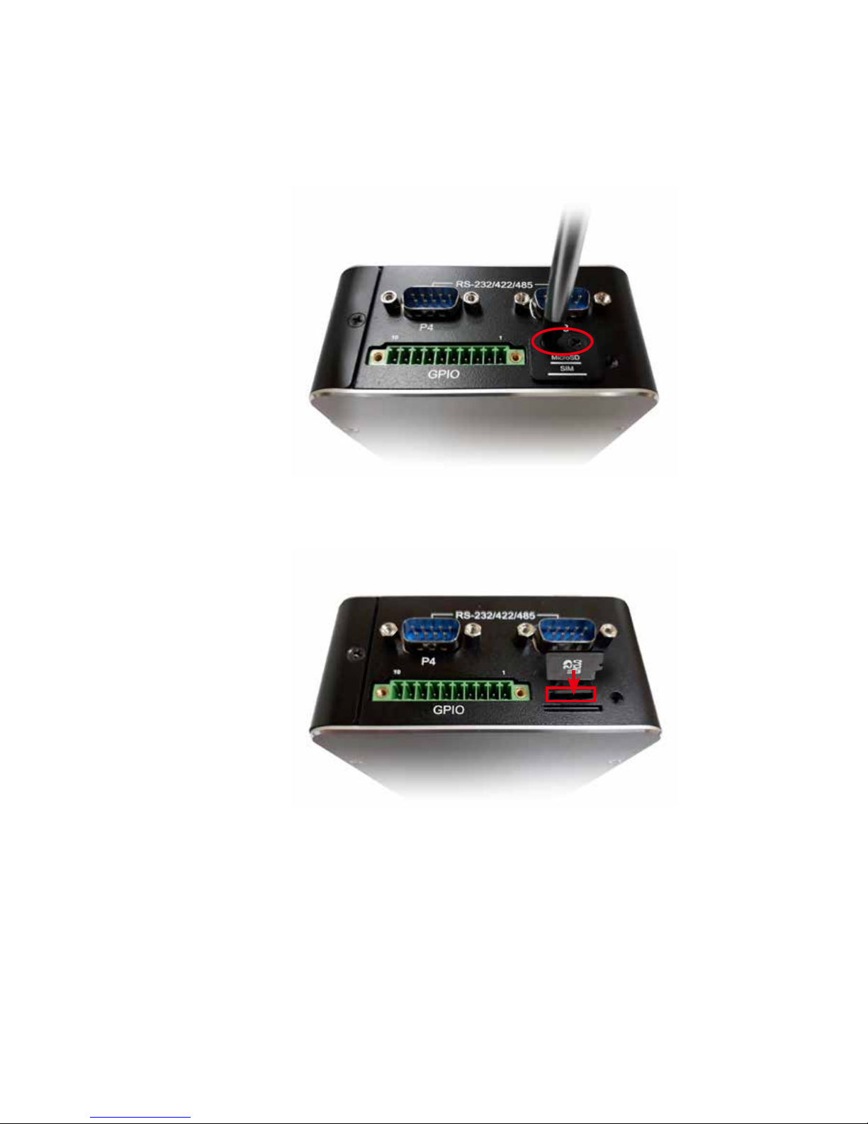
3.2 Installing MicroSD Card
Step 1 Unscrew the 2 screws on the MicroSD & SIM card cover.
Step 2 Push into SD slot.
Page 38
32
HARDWARE INSTALLATION©Vecow VIG-100 User Manual
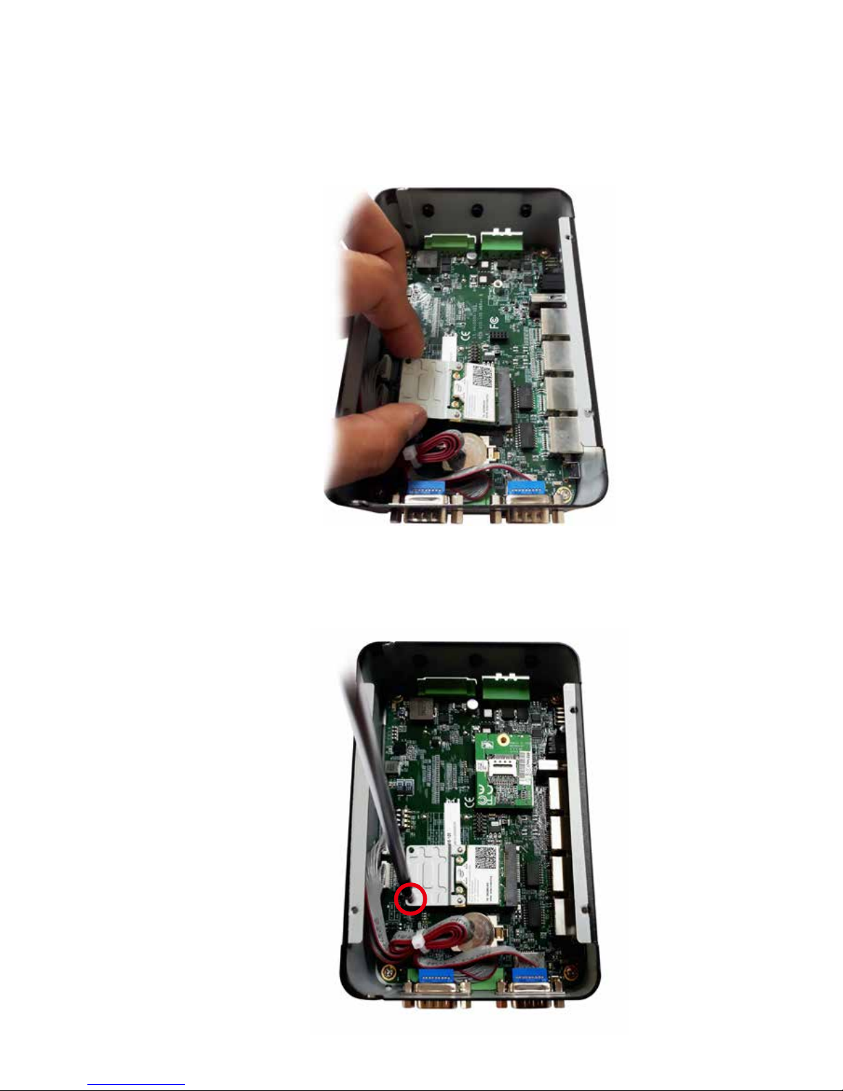
3.3 Installing Mini PCIe Card
Step 1 Insert the Mini PCIe module into the slot at a 45-degree angle.
Step 2 Push the Mini PCIe card down and use the provided mounting
screw to lock onto motherboard.
Page 39
33
HARDWARE INSTALLATION
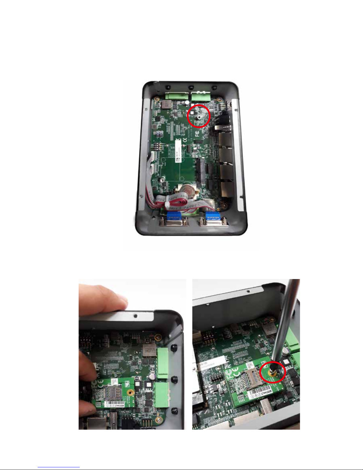
Step 1 Find out NB-IoT Module screw hole.
3.4 Installing LPWAN NB-IoT Module
Step 2 Align the NB-IoT Module
to the screw hole.
Step 3 Secure with a M3 screw.
Page 40
34
HARDWARE INSTALLATION©Vecow VIG-100 User Manual
1 2 3
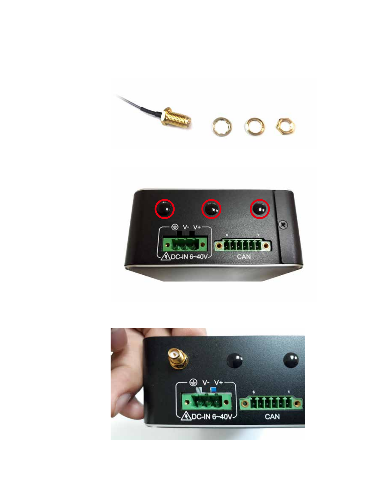
3.5 Installing Antenna Cable
Step 1 Check antenna cable and washers.
Step 2 Remove the hole plugs on VIG-100 top side.
Step 3 Fasten washer 1, washer 2, and washer 3 on antenna cable
connectors.
Page 41
35
HARDWARE INSTALLATION
3.6 Installing SIM Card
Step 2 Push into SIM slot.
Step 1 Unscrew the 2 screws on the MicroSD & SIM card cover.
Page 42
36
HARDWARE INSTALLATION©Vecow VIG-100 User Manual
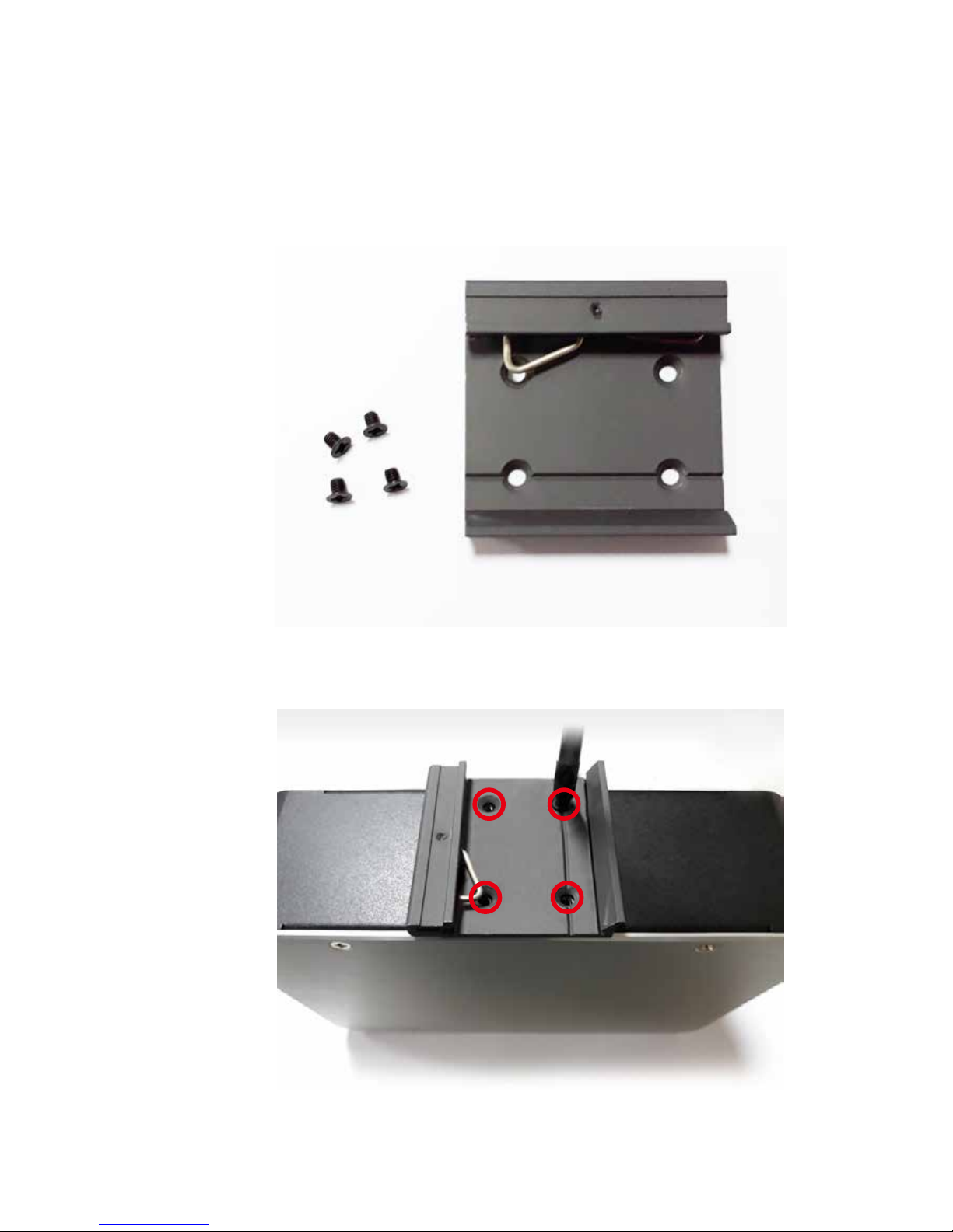
M3 screw X4
Din rail kit X1
3.7 Mounting Your VIG-100
3.7.1 DIN-RAIL
Step 1 DIN rail parts as follows.
Step 2 Lock the screws.
Page 43
37
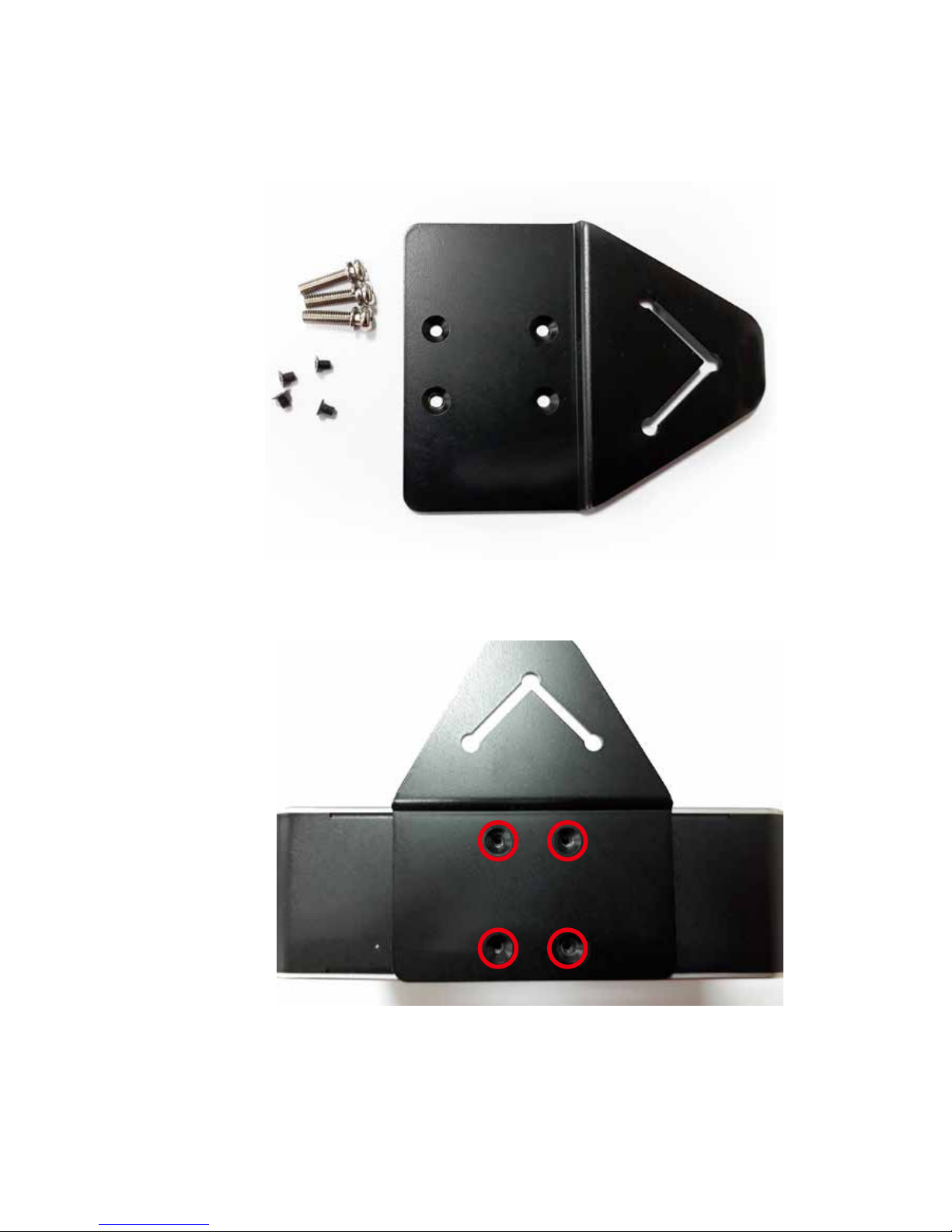
HARDWARE INSTALLATION
M3 screw X4
Din rail kit X1
Step 1 Wall Mount parts as follows.
3.7.2 Wall Mount
Step 2 Lock the screws.
Wall Mount screw X3
Page 44
38
HARDWARE INSTALLATION©Vecow VIG-100 User Manual
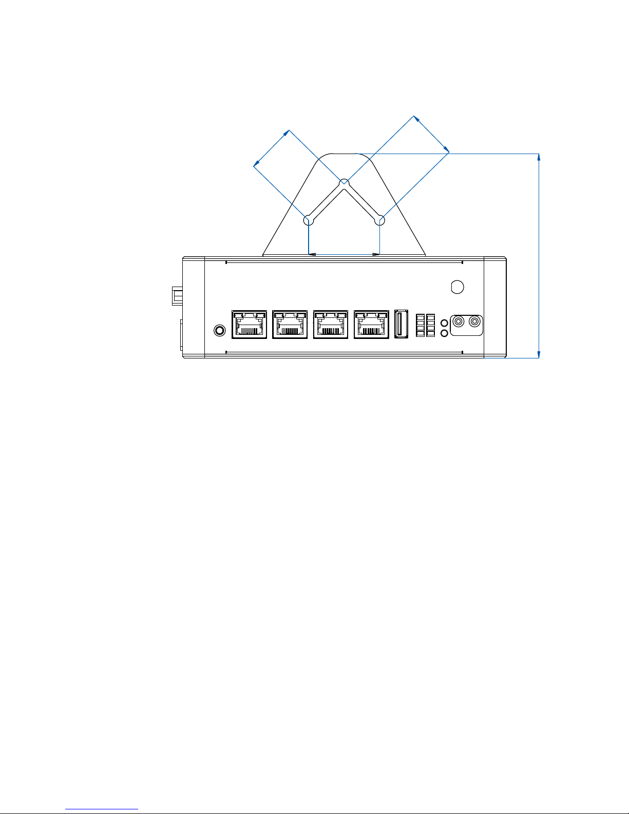
100.7 (3.97”)
35.0 (1.38”)
25.0 (0.98”)
25.0 (0.98”)
Step 3 Please locate your the screw holes according to the size of the gure
below.
Page 45
39
INITIAL LOGIN
4
SOFTWARE SETUP
4.1 Console Port Login
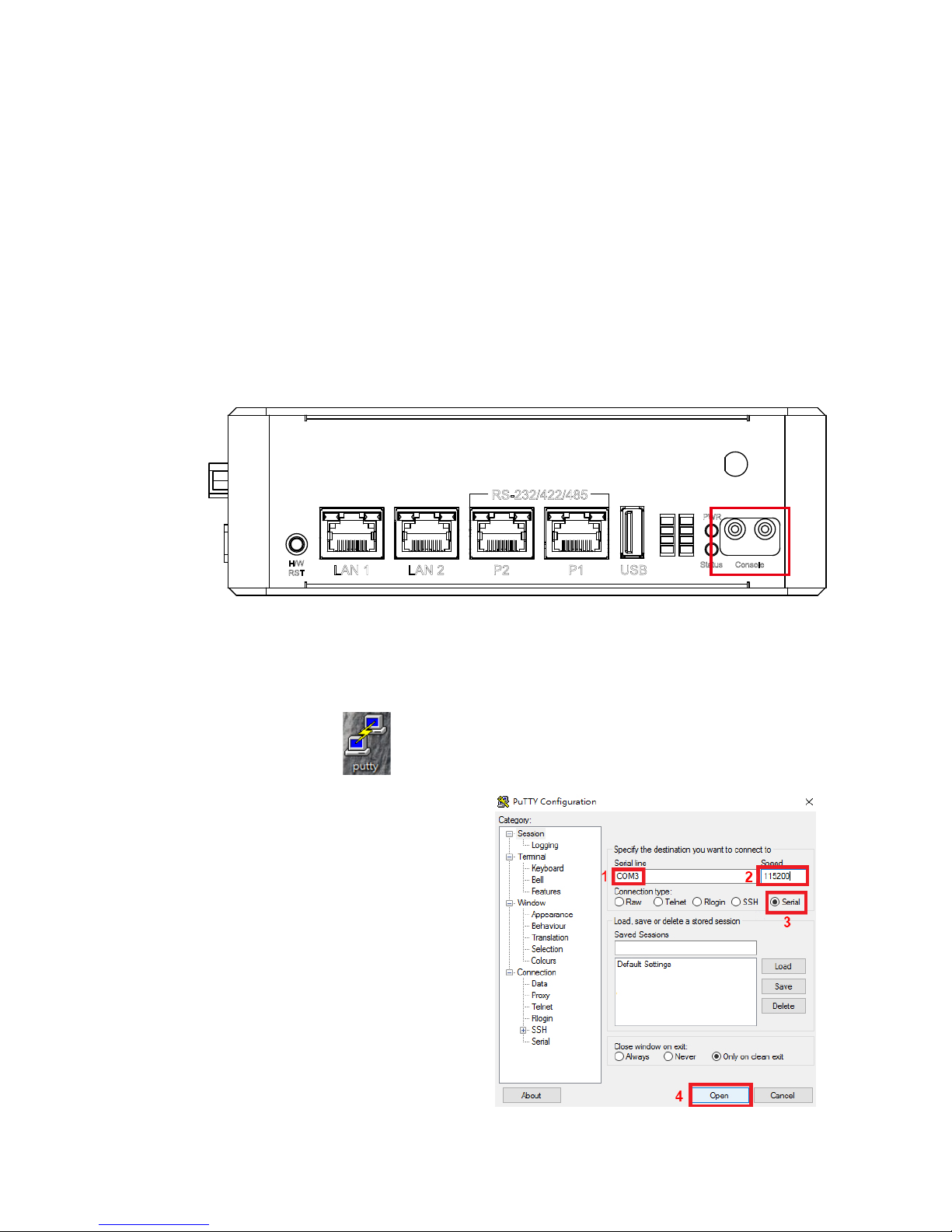
2. Go to “Device Manger,” check “COM & LPT” and you will nd “USB
SerialPort (COM3)” as Console Port.
Note : This COM number is not a xed value and depends on your own
device. We take COM3 here for instance.
3. Please click “ ” and choose “Run as Administrator” to bring up
the PuTTY Conguration window.
4. Go to Category > Serial, enter
the COM (COM3) port
you connected your host
computer to VIG-100 and
enter the following parameters:
1
2
3
4
5
6
7
8
PWR
H/W
RST
Status
LAN 1 LAN 2 P2 P1 USB
Console
RS-232/422/485
1. Set up a connection between your host computer and VIG-100 console port.
Page 46
40
BIOS AND DRIVER SETTING©Vecow VIG-100 User Manual
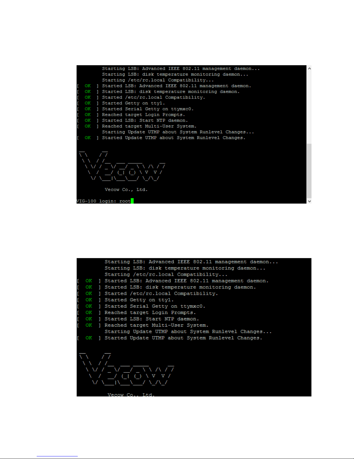
5. Make sure VIG-100 Power ON, an then a series of messages may appear.
Enter “root” to login.
6. Please remember to change the default password “root” to avoid
unauthorized access.
Note : Please kindly note that the passward is not shown while typing.
Page 47
41
INITIAL LOGIN
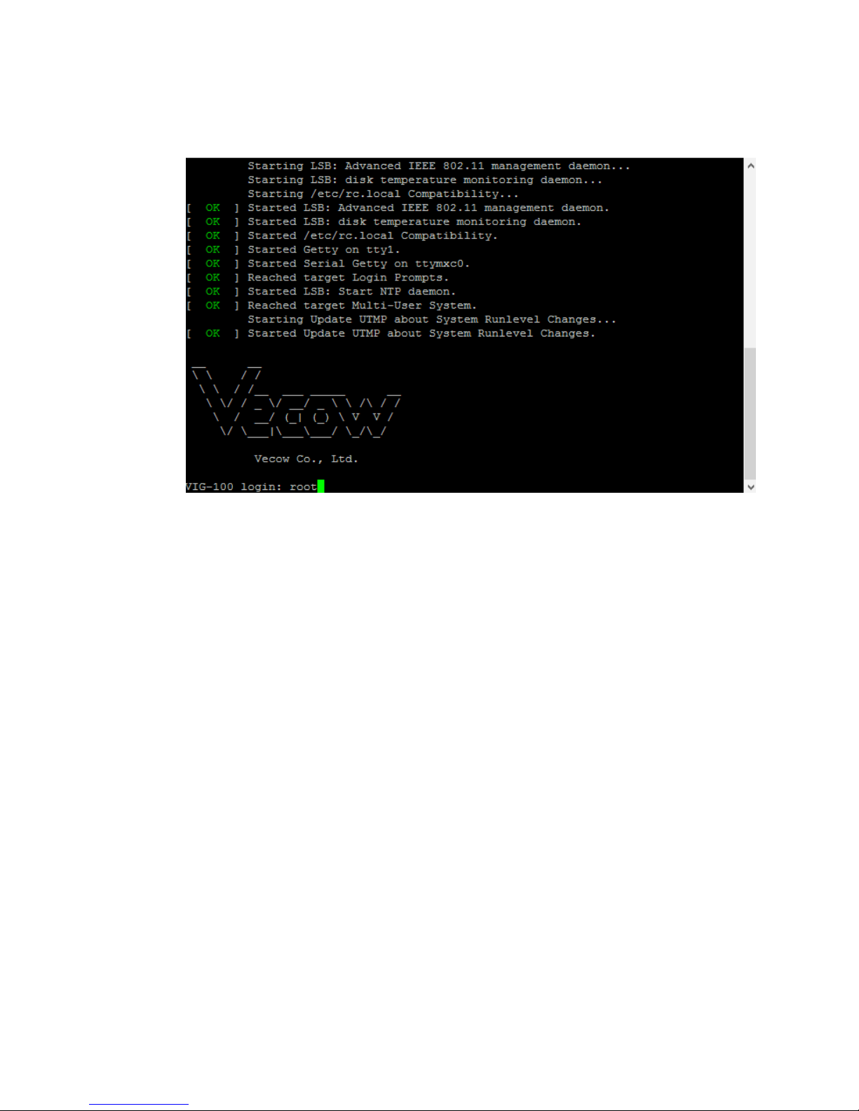
7. And then“root@VIG-100:~#” will appear. You are ready to begin conguring
your system.
Page 48
42
BIOS AND DRIVER SETTING©Vecow VIG-100 User Manual
4.2 COM Port
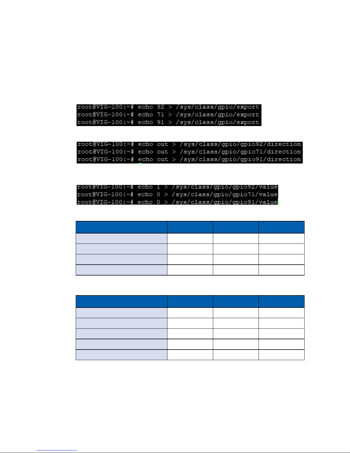
There is some necessary conguration before user starts COM Port transmission.
For example, to set COM Port 1 as RS232 mode, please follow the steps as
below:
1. Export GPIO 92, 71, 91 pins
3. Follow the truth table to set COM Port 1 mode pin to "High, Low & Low."
(RS232 mode)
2. Set GPIO 92, 71, 91 as output pins
Mode Mode Pin 0 Mode Pin 1 Mode Pin 2
COM Port 1 (/dev/ttymxc2) GPIO 92 GPIO 71 GPIO 91
COM Port 2 (/dev/ttymxc4) GPIO 87 GPIO 83 GPIO 81
COM Port 3 (/dev/ttymxc6) GPIO 88 GPIO 84 GPIO 70
COM Port 4 (/dev/ttymxc7) GPIO 72 GPIO 69 GPIO 79
Figure 4-2-1: COM Port mode GPIO pin mapping and device name
Mode Mode Pin 0 Mode Pin 1 Mode Pin 2
Loop Back Low Low Low
RS232 High Low Low
RS485 Low High Low
RS422(5-wire) High High Low
RS422(9-wire) Low Low High
Figure 4-2-2: COM Port mode truth table
Page 49

43
INITIAL LOGIN
4.4 GPIO & LED
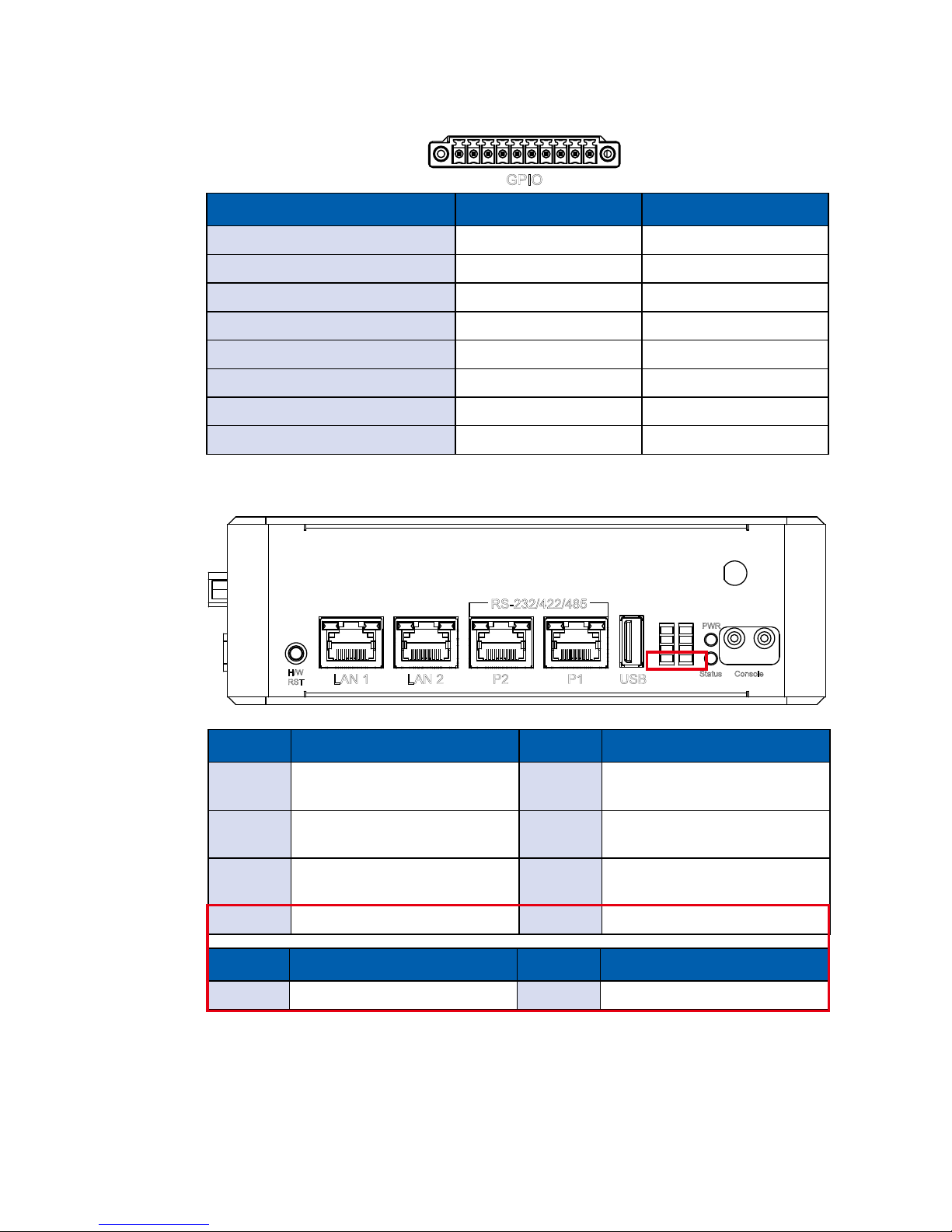
VIG-100 is with 8 Programmable GPIO and 2 Programmable LED (totally 8
LED, but only 2 programmable), which is similar to COM port conguration. User
needs to gure out the pin mapping before programming. The following steps
are example to set GPIO 1 as output high, and turn on LED 4:
1: Set GPIO 1 as output high
2: Turn LED 4
4.3 I2C interface
There are two different I2C buses on VIG-100 system, I2C-1 is for SOM internal
use, and I2C-2 is connected to RTC and external I2C Header. If user wants to
have external I2C header, please avoid the occupied I2C address.
Figure 4-3-1: I2C device address table
Page 50
44
BIOS AND DRIVER SETTING©Vecow VIG-100 User Manual
GPIO
10 1
Mode SOM GPIO number Connecter pin
GPIO 1 GPIO 64 Pin 2
GPIO 2 GPIO 133 Pin 3
GPIO 3 GPIO 131 Pin 4
GPIO 4 GPIO 120 Pin 5
GPIO 5 GPIO 67 Pin 6
GPIO 6 GPIO 66 Pin 7
GPIO 7 GPIO 68 Pin 8
GPIO 8 GPIO 114 Pin 9
Figure 4-4-1: Programmable GPIO pin mapping
1
2
3
4
5
6
7
8
PWR
H/W
RST
Status
LAN 1 LAN 2 P2 P1 USB
Console
RS-232/422/485
LED No. LED Status LED No. LED Status
1
P3 (COM3)
TX Transport Blinking
5
P4 (COM4)
TX Transport Blinking
2
CAN 1
TX Transport Blinking
6
CAN 2
TX Transport Blinking
3
Mini PCIe Slot
USB Detect LED
7
MicroSD Card
Detect LED
4 Programmable LED 8 Programmable LED
LED No. SOM GPIO number LED No. SOM GPIO number
LED 4 GPIO 136 LED 8 GPIO 135
Figure 4-4-2: Programmable LED pin mapping
Page 51
45
INITIAL LOGIN
4.5 Network
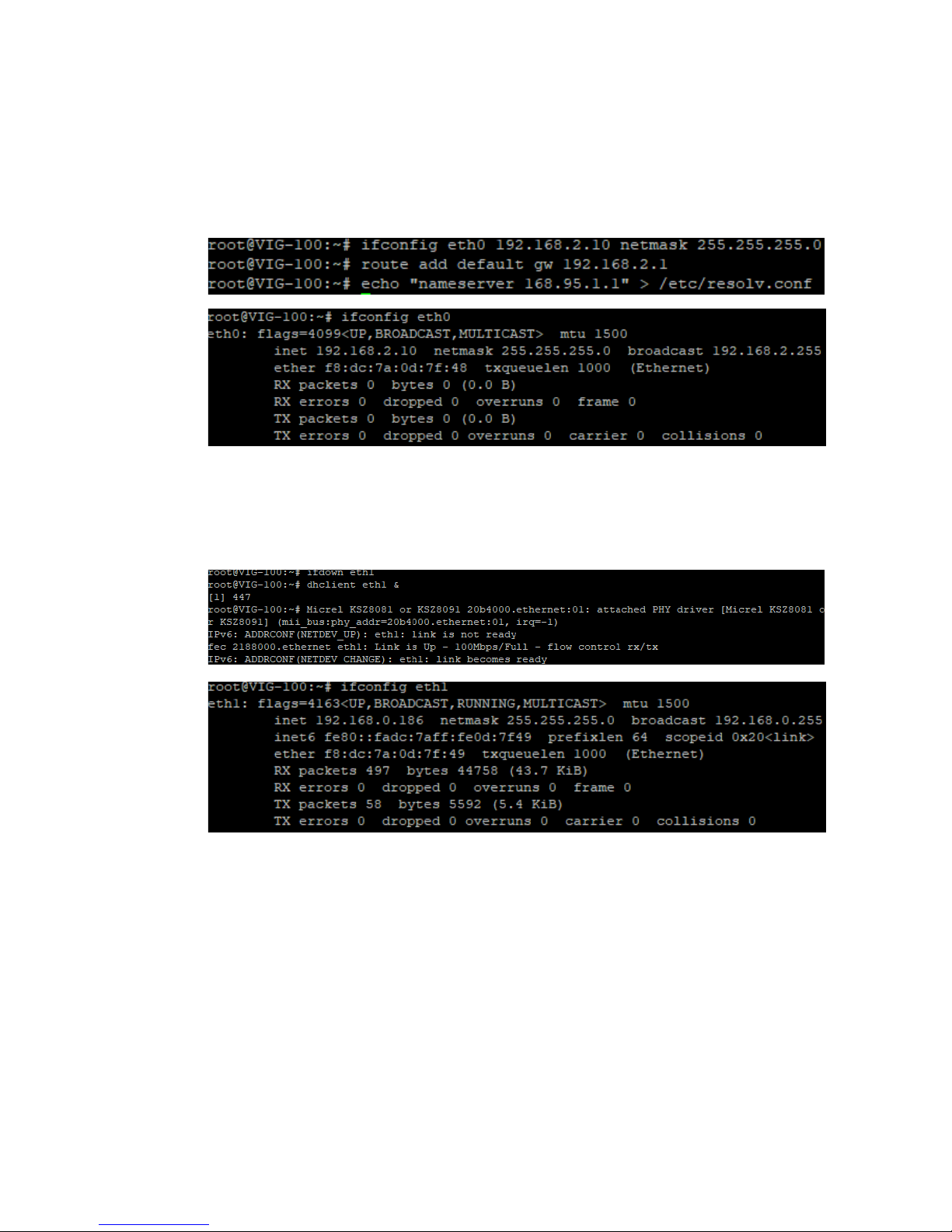
VIG-100 supports two 100Mbps Ethernet RJ45/M12 type interfaces. User can
congure their IP by static assign as following:
Figure 4-5-1: Congure Static IP
Or using DHCP client (e.g. dhclient) to grant IP address automatically:
Figure 4-5-2: Congure IP via DHCP client
Page 52
46
BIOS AND DRIVER SETTING©Vecow VIG-100 User Manual
4.6 CANbus
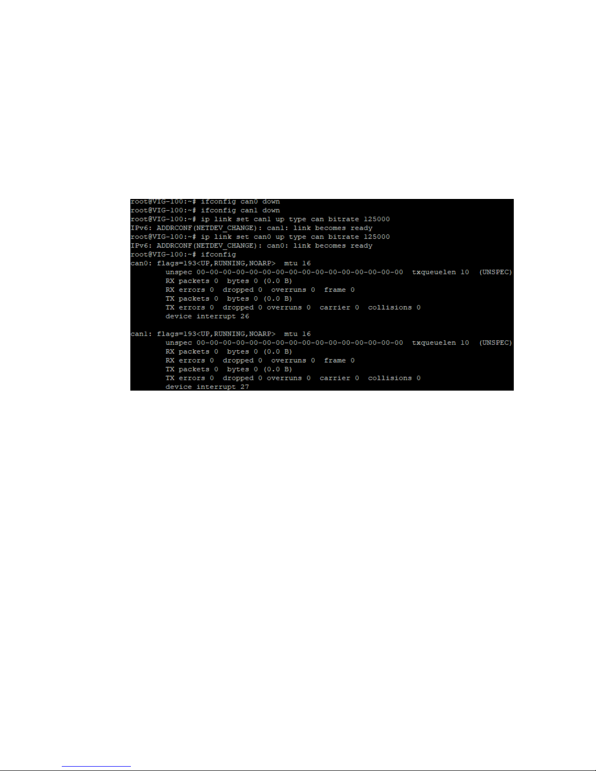
VIG-100 is also integrated with two CANbus supporting CAN 2.0B protocol, and
the CAN protocol was primarily designed to be used as a vehicle serial data bus
meeting the specic requirements of this eld. Simply follow the commands to
establish SocketCAN interface:
1: Enable can0 & can1 with 125000 bitrate
Figure 4-6-1: Congure CANbus
Page 53
47
Appendix A
A
APPENDIX A : POWER CONSUMPTION
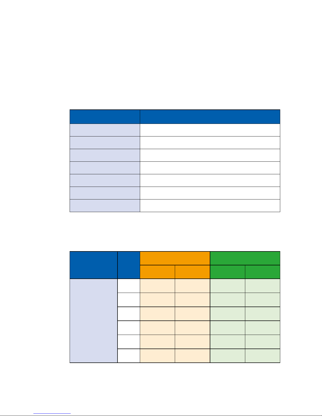
Testing Board VIG-120
RAM : 512MB (On Board)
USB 2.0-1 : Transcend USB 3.0 Flash 8GB
LAN 1 : 100Mbps
LAN 2 : 100Mbps
Graphics Output : USB Console (with Putty)
Test Program : Software RD provide
Power Source : Chroma 62006P-100-25
Processor
Power
Input
Idle status CPU usage
less 5%
Run over 90% CPU usage
Max
Current
Max
Consumption
Max
Current
Max
Consumption
NXP i.MX6 UltraLite
696MHz
Arm
®
Cortex®-A7
processor
06V 0.253A 01.52W 0.287A 01.72W
09V 0.175A 01.58W 0.211A 01.90W
12V 0.144A 01.73W 0.170A 02.04W
24V 0.093A 02.23W 0.093A 02.23W
36V 0.074A 02.66W 0.084A 03.02W
40V 0.071A 02.84W 0.079A 03.16W
Power on and boot to Linux Core
Page 54

For further support information, please visit www.vecow.com
This document is released for reference purpose only.
All product offerings and specications are subject to change without prior notice.
No part of this publication may be reproduced in any form or by any means, electric, photocopying, or recording,
without prior authorization from the publisher.
The rights of all the brand names, product names, and trademarks belong to their respective owners.
© Vecow Co., Ltd. 2018. All rights reserved.
 Loading...