

Vecima Networks WRM1151 Users Manual

NCL1135 User Manual
Version 1.0

WaveRider Communications Inc.
Software License Agreement
This is a legal agreement between you (either an individual or an entity) and WaveRider Communications Inc. for the use
of WaveRider computer software, hereinafter the “LICENS E D SO FTWARE”.
By using the LICENSED SOFTWARE installed in this product, you acknowledge that you have read this license
agreement, understand it, and agree to be bound by its terms. You further agree that it is the full and complete
agreement between you and WaveRider Communi ca tions Inc., supersedin g al l prior written or verbal agree m ents of an y
kind related to the LICENSED SOFTWARE. If you do not understand or do not agree to the terms of this agreement, you
must cease using the LICENSED SOFTWARE immediately.
1 GRANT OF LICENSE—This License Agreement permits you to use one copy of the L ICENSED SOFTWARE.
2. COPYRIGHT—The LICENSED SOFTWARE is owned by WaveRider Communications Inc. and is protected by
copyright laws and inter national treaty provisions; th er ef or e, you mu st treat t he LI C ENSED SOFTWARE like
any other copyrighted m at er ial (e. g. , a book or ma gazine). You may not copy the written materials
accompanying the LICENSED SOFTWARE.
3. OTHER RESTRICT IONS—You may not rent or lease the LICENSED SOFTWARE. You may not reverse
engineer, decompile, or disassemble t he LI C ENSED SOFTWARE.
4. LIMITED WARRANTY—The L ICENSED SOFTWARE is provided “a s is” w i t hou t any w arranty of any kind,
either expressed or imp lie d, incl udi ng, but not limited to, the implied w ar ra nt ies of m er chantability and fitness
for a particular purpose. The entire risk as to the quality and per fo rm a nce of the LICENSED SOFTWARE is
with you, the licensee. If the LICENSED SOFTWARE is defective, you assume the risk and liability for the
entire cost of all necess ar y repair, service, or correction.
Some states/jurisdictions do not allow the exclusion of implied warranties, so the above exclusion
may not apply to you. This warranty gives you specific legal rights, and you may have other rights,
which vary from state/jurisdiction to state/jurisdiction.
WaveRider Communications Inc. does not warrant that the functions contained in the LICENSED
SOFTWARE will meet your requirement s, or that the o peration of t he LICENSED SOFTWARE wil l be
error-free or uninterrupted.
5. NO OTHER W ARRANTIE S—To the maximum ex tent permitted by appl icable law , W aveRi der Communi cation s
Inc. disclaims all other warranties, either express or implied, including, but not limited to, the implied warranties
of merchantability and fitnes s fo r a part icular purpose, with rega rd to the LICENSED SOFTWARE and the
accompanying written materials.
6. NO LIABILITY FOR CONSEQUENTIAL DAMAGES—To the maximum extent permitted by app lic abl e l aw, in
no event shall WaveRider Com m unications Inc. or its supp lier s be liable for any damage s w hatsoever
(including, witho ut lim itation, damages for loss of bu si ness profits, business inte rr uption, loss of business
informati on, o r an y ot he r pe cu ni ary lo ss ) ar i si ng f ro m t he use of or in a bi lit y t o u se t he L ICE NSED SOF TWARE,
even if WaveRider Communications Inc. has been advised of the possibility of such damages, or for any claim
by any other pa r ty.
Because some states/jurisdictio ns d o not a llo w the exclusion or limitation of liability for conse quenti al
or incidental damages, the a bov e l imi tation m ay not apply to you.
In no event will WaveRider’s liability exceed the amount paid for the LICENSED SOFTWARE.

The following are trademarks or registered trademarks of
their respective companies or organizations:
Microsoft Internet Explorer/Microsoft Corporation
Netscape/Netscape Communications Corporation
© 2000 by WaveRider Communications Inc. All rights
reserved. This manual may not be reproduced by any means
in whole or in part without the exp ress written permission of
WaveRider Communications Canada Inc.
Version 1.0, July 2000

Warranty
In the following warranty text, “WaveRider®” shall mean WaveRider Com m u ni cations Inc.
This WaveRider product is wa rran ted aga inst defe cts in materi al an d wor kma nshi p for a pe riod of on e (1) ye ar from th e
date of purchase. This limited wa rranty extends only to the origi nal purchaser. During this warranty perio d WaveRider
will, at its option, either repair or replace products that prove t o be defective .
For warranty service or repair, the product must be returned to a service facility designated by WaveRider. Authorization
to return products must be obtained prior to shipment. The WaveRider RMA number must be on the shipping
documentation so that the service facility will accept the product. The buyer shall pay all shipping charges to WaveRider
and WaveRider shall pay shippi ng charges to retur n the product to the buyer within Canad a or the USA. For all other
countries, the buyer shall pay shipping charges as well as duties and taxes incur red in shipping products to or f rom
WaveRider.
WaveRi der warrants that the fir m w are designed by i t for use with the unit will execute its programming instructions when
properly installed on the unit. WaveRider does not warrant that the operation of the unit or firmware will be uninterrupted
or error-free.
Limitation of Warr anty
The foregoing wa rranty shall not apply to defec ts resulting from improper or inadequate maintenan ce by the buyer,
buyer-supplied interfa cing, unauthorized mo dification or misuse, operation outside the enviro nmental specifications for
the product, or improper site preparation or maintenance or exposure to abnormal physical or electrical stress or
accident. No other warranty is expressed or implied. WaveRider specifically disclaims the implied warranties of
merchantability and fit nes s f o r any par ticular purpose.
No Liability for Consequential Damages
To the maximum extent permitted by applicable law, in no event shall WaveRider or its suppliers be liable for any
damages whatsoever (including, without limitation, damages for loss of business profits, business interruption, loss of
business information, or any other pecuniary loss) arising from the use of or inability to use the product, even if
WaveRider has been advised of the possibility of such damages , or for any claim by any other party.
Because some states/jurisdictions do not allow the exclusion or limitation of liability for consequential or incidental
damages, the above lim itation ma y not apply to you.
In no event will WaveRider’s liability exceed the amount paid for the product.
Regulatory Notices
This equipment has be en tested an d found to co mply wi th the lim its for a Class A Int entional R adiator, pursuant to Part
15 of the FCC Re gu lations, and RSS- 210 of t he I C Re gula tions. T hes e lim its are intend ed to provide p rotect ion aga inst
harmful interference when the equipm ent is operated in a commerc i al /b usiness/industrial environment.
This equipment gene rates, uses, and can r adiate radio frequ ency energy and, if no t installed and used in accor dance
with the instruction manual, ma y cause harmf ul interference t o radio comm unications. Ho wever, there is no guarante e
that interference will not occur in a particular inst allation.
Notice to User
Any changes or mod ifications to equipmen t that are not expressly approved by the manufac turer may void the use r’s
authority to oper ate the eq uipme nt. The NCL1135 contains no us er-servi ceable parts. Unaut horiz ed openi ng of th e unit
voids this warranty.

Contents
Preface . . . . . . . . . . . . . . . . . . . . . . . . . . . . . . . . . . . . . . . . . . . . . . . . . . . . . . . . . . . . . . . . . .ix
1 NCL1135 Overview . . . . . . . . . . . . . . . . . . . . . . . . . . . . . . . . . . . . . . . . . . . . . . . . . . . . . 1
1.1 Introduction to the NCL1135 . . . . . . . . . . . . . . . . . . . . . . . . . . . . . . . . . . . . . . . . . . 1
1.2 Spread-Spectrum Radio Technology. . . . . . . . . . . . . . . . . . . . . . . . . . . . . . . . . . . . 3
2 Network Considerations . . . . . . . . . . . . . . . . . . . . . . . . . . . . . . . . . . . . . . . . . . . . . . . . 5
2.1 Network Topology . . . . . . . . . . . . . . . . . . . . . . . . . . . . . . . . . . . . . . . . . . . . . . . . . . 5
2.1.1 Point-to-Point . . . . . . . . . . . . . . . . . . . . . . . . . . . . . . . . . . . . . . . . . . . . . . . 6
2.1.2 Repeater . . . . . . . . . . . . . . . . . . . . . . . . . . . . . . . . . . . . . . . . . . . . . . . . . . 6
2.1.3 Point-to-Multipoint . . . . . . . . . . . . . . . . . . . . . . . . . . . . . . . . . . . . . . . . . . . 7
2.2 Bridging and Routing Network Configurations. . . . . . . . . . . . . . . . . . . . . . . . . . . . . 8
2.2.1 Point-to-Multipoint Bridging Network . . . . . . . . . . . . . . . . . . . . . . . . . . . . . 8
2.2.2 Point-to-Multipoint Routing Network . . . . . . . . . . . . . . . . . . . . . . . . . . . . . 9
2.3 Planning an NCL1135 Configuration . . . . . . . . . . . . . . . . . . . . . . . . . . . . . . . . . . . 10
3 Configuring the NCL1135 . . . . . . . . . . . . . . . . . . . . . . . . . . . . . . . . . . . . . . . . . . . . . . . 11
3.1 Connecting and Initializing the NCL1135. . . . . . . . . . . . . . . . . . . . . . . . . . . . . . . . 12
3.1.1 Changing the NCL1135 Password . . . . . . . . . . . . . . . . . . . . . . . . . . . . . . 14
3.1.2 Setting the NCL1135 System Name . . . . . . . . . . . . . . . . . . . . . . . . . . . . 15
3.1.3 Resetting an NCL1135 to Factory Settings . . . . . . . . . . . . . . . . . . . . . . . 15
3.2 Configuring the NCL1135 . . . . . . . . . . . . . . . . . . . . . . . . . . . . . . . . . . . . . . . . . . . 16
3.2.1 Setting the Radio Configuration . . . . . . . . . . . . . . . . . . . . . . . . . . . . . . . . 16
3.2.2 Setting the IP Configuration . . . . . . . . . . . . . . . . . . . . . . . . . . . . . . . . . . . 18
Setting the DHCP Relay Configuration . . . . . . . . . . . . . . . . . . . . . . . . . 19
Setting the SNMP Configuration . . . . . . . . . . . . . . . . . . . . . . . . . . . . . . 20
Setting the DNS Resolver Configuration . . . . . . . . . . . . . . . . . . . . . . . 21
3.3 Examples of Bridging and Routing Configurations . . . . . . . . . . . . . . . . . . . . . . . . 22
3.3.1 Point-to-Multipoint Bridging Network . . . . . . . . . . . . . . . . . . . . . . . . . . . . 22
3.3.2 Point-to-Multipoint Routing Network . . . . . . . . . . . . . . . . . . . . . . . . . . . . 25
3.4 Updating an NCL1135 Using Remote Connections. . . . . . . . . . . . . . . . . . . . . . . . 30
3.4.1 Establishing an FTP Connection . . . . . . . . . . . . . . . . . . . . . . . . . . . . . . . 30
3.4.2 Establishing a Telnet Session . . . . . . . . . . . . . . . . . . . . . . . . . . . . . . . . . 31
3.4.3 Establishing a Web Browser Connection . . . . . . . . . . . . . . . . . . . . . . . . . 31
4 Testing . . . . . . . . . . . . . . . . . . . . . . . . . . . . . . . . . . . . . . . . . . . . . . . . . . . . . . . . . . . . . . 33
4.1 Performing a Ping Test . . . . . . . . . . . . . . . . . . . . . . . . . . . . . . . . . . . . . . . . . . . . . 33
5 Deploying the NCL1135 . . . . . . . . . . . . . . . . . . . . . . . . . . . . . . . . . . . . . . . . . . . . . . . . 35
5.1 Optimizing Signal Strength . . . . . . . . . . . . . . . . . . . . . . . . . . . . . . . . . . . . . . . . . . 35
5.1.1 Running the Continuous Transmit (Tx) Test . . . . . . . . . . . . . . . . . . . . . . 35
5.1.2 Running the Continuous Receive (Rx) Test . . . . . . . . . . . . . . . . . . . . . . . 37
5.1.3 Performing the Transmit/Receive Loopback Test . . . . . . . . . . . . . . . . . . 39
APCD–NC003–1.0 v

6 Operational Statistics . . . . . . . . . . . . . . . . . . . . . . . . . . . . . . . . . . . . . . . . . . . . . . . . . . 41
6.1 Displaying the Radio Packet Error Rate (PER) . . . . . . . . . . . . . . . . . . . . . . . . . . 41
6.2 Displaying the Operational Statistics . . . . . . . . . . . . . . . . . . . . . . . . . . . . . . . . . . 44
6.2.1 Interface Statistics . . . . . . . . . . . . . . . . . . . . . . . . . . . . . . . . . . . . . . . . . . 44
6.2.2 IP Statistics . . . . . . . . . . . . . . . . . . . . . . . . . . . . . . . . . . . . . . . . . . . . . . . . 47
6.2.3 Radio Statistics . . . . . . . . . . . . . . . . . . . . . . . . . . . . . . . . . . . . . . . . . . . . . 49
7 Troubleshooting . . . . . . . . . . . . . . . . . . . . . . . . . . . . . . . . . . . . . . . . . . . . . . . . . . . . . . 51
7.1 Verifying NCL1135 Routing . . . . . . . . . . . . . . . . . . . . . . . . . . . . . . . . . . . . . . . . . 53
7.1.1 Verify the NCL1135 Routing Table . . . . . . . . . . . . . . . . . . . . . . . . . . . . . . 53
Appendix A NCL1135 Command-Line Syntax . . . . . . . . . . . . . . . . . . . . . . . . . . . . . . . 55
Appendix B Abbreviations and Terminology . . . . . . . . . . . . . . . . . . . . . . . . . . . . . . . . 63
Appendix C Operating Channel Frequencies . . . . . . . . . . . . . . . . . . . . . . . . . . . . . . . 67
Appendix D NCL1135 Specifications . . . . . . . . . . . . . . . . . . . . . . . . . . . . . . . . . . . . . . 69
Appendix E Configuration Data Record . . . . . . . . . . . . . . . . . . . . . . . . . . . . . . . . . . . . 71
vi APCD–NC003–1.0

Figures
Figure 1 NCL1135 Network Examples . . . . . . . . . . . . . . . . . . . . . . . . . . . . . . . . . . . . 1
Figure 2 Point-to-Point Application . . . . . . . . . . . . . . . . . . . . . . . . . . . . . . . . . . . . . . . 6
Figure 3 Repeater Application . . . . . . . . . . . . . . . . . . . . . . . . . . . . . . . . . . . . . . . . . . . 6
Figure 4 Point-to-Multipoint Application . . . . . . . . . . . . . . . . . . . . . . . . . . . . . . . . . . . . 7
Figure 5 Point-to-Multipoint Bridging Network Example . . . . . . . . . . . . . . . . . . . . . . . 8
Figure 6 Point-to-Multipoint Routing Network Example . . . . . . . . . . . . . . . . . . . . . . . . 9
Figure 7 NCL1135 Configuration Planning Flowchart . . . . . . . . . . . . . . . . . . . . . . . . 10
Figure 8 NCL1135 Connections . . . . . . . . . . . . . . . . . . . . . . . . . . . . . . . . . . . . . . . . 12
Figure 9 Console Port Pin-out Diagram . . . . . . . . . . . . . . . . . . . . . . . . . . . . . . . . . . 13
Figure 10 Example Point-to-Multipoint Bridging Network . . . . . . . . . . . . . . . . . . . . . . 22
Figure 11 Example Point-to-Multipoint Routing Network . . . . . . . . . . . . . . . . . . . . . . . 25
APCD–NC003–1.0 vii

Tables
Table 1 Radio Packet Error Rate Assessment . . . . . . . . . . . . . . . . . . . . . . . . . . . . . 43
Table 2 Interface Statistics . . . . . . . . . . . . . . . . . . . . . . . . . . . . . . . . . . . . . . . . . . . . 46
Table 3 IP Statistics . . . . . . . . . . . . . . . . . . . . . . . . . . . . . . . . . . . . . . . . . . . . . . . . . 48
Table 4 Radio Statistics . . . . . . . . . . . . . . . . . . . . . . . . . . . . . . . . . . . . . . . . . . . . . . 49
Table 5 Common Problems and Solutions . . . . . . . . . . . . . . . . . . . . . . . . . . . . . . . . 51
Table 6 NCL1135 Command-Line Syntax Conventions . . . . . . . . . . . . . . . . . . . . . . 55
Table 7 Command-Line Shortcuts and Getting Help . . . . . . . . . . . . . . . . . . . . . . . . 56
Table 8 NCL1135 Command-line Syntax Descriptions . . . . . . . . . . . . . . . . . . . . . . 56
Table 9 Acronyms and Abbreviations . . . . . . . . . . . . . . . . . . . . . . . . . . . . . . . . . . . . 63
Table 10 NCL1135 Network Terminology . . . . . . . . . . . . . . . . . . . . . . . . . . . . . . . . . . 65
Table 11 Radio Specifications . . . . . . . . . . . . . . . . . . . . . . . . . . . . . . . . . . . . . . . . . . 69
Table 12 Ethernet Interface Specifications . . . . . . . . . . . . . . . . . . . . . . . . . . . . . . . . 70
Table 13 Power Supply Specifications . . . . . . . . . . . . . . . . . . . . . . . . . . . . . . . . . . . 70
Table 14 Environmental Specifications . . . . . . . . . . . . . . . . . . . . . . . . . . . . . . . . . . . 70
viii APCD–NC003–1.0

Preface
About this Manual
WaveRider recommends that you read the following sections before you install and operate
the NCL1135:
•
Software License Agreement
•
Warranty
•
Regulatory Notices
•
Warnings and Advisories
This NCL1135 User Manual provides you with information necessary for planning, installing,
and operating an NCL1135-based system. The information has been organized in the
following sections:
on page iv
on page ii
on page x
on page xii
Chapter 1 Provides an overview of the NCL1135 and the spread-spectrum radio
technology.
Chapter 2 Describes some typical configurations and provides a flowchart to assist you
in planning your network.
Chapter 3 Provides the procedures to set up and configure the NCL1135.
Chapter 4 Describes a ping test that confirms the NCL1135 is configured and ready to
be deployed.
Chapter 5 Provides three tests useful when deploying an NCL1135.
Chapter 6 Describes how to obtain the NCL1135 operational statistics.
Chapter 7 Lists typical NCL1135 problems, possible causes, and solutions.
Appendix A Lists all commands available for the NCL1135.
Appendix B Provides a list of acronyms and abbreviations and a list of the NCL1135
wireless network terminology used in this manual.
Appendix C Lists the channel frequency set for each WaveRider regulatory domain.
Appendix D Provides the NCL1135 technical specifications.
Appendix E Contains a form that you can use to record the configuration information.
NOTE: The information contained in this manual is subject to change
without notice.
APCD–NC003–1.0 ix

Regulatory Notices
Industry Canada
The NCL1135 complies with IC RSS–210.
Operators must be familiar with IC RSS–210 and RSS–102.
The IC certification number for the NCL1135 is 32251021662A.
Federal Communications Commission
The NCL1135 complies with FCC Part 15 Regulations.
The FCC ID for the NCL1135 is OOX-NCL1100.
The transmitter of this device complies with Part 15.247 of the FCC Rules.
Operators must be familiar with the requirements of the FCC
Part 15 Regulations prior to operating any link using this
equipment. For installations outside the United States, contact
local authorities for applicable regulations.
WARNING!
Interference Env ironment
Manufacturers and operators of spread-spectrum devices are reminded that the operation of
these devices is subject to the conditions that:
• Any received interference, including interference from industrial, scientific, and
medical (ISM) operations, must be accepted; and
• These devices are not permitted to cause harmful interference to other radio services.
If the operation of these systems does cause harmful interference, the operator of the spreadspectrum system must correct the interference problem, even if such correction requires the
Part 15 transmitter to cease operation. The FCC does not exempt spread-spectrum devices
from this latter requirement regardless of the application. The FCC strongly recommends that
utilities, cellular stations, public safety services, government agencies, and others that provide
critical communication services exercise due caution to determine if there are any nearby
radio services that can be affected by their communications.
x APCD–NC003–1.0

Operational Requirements
In accordance with the FCC Part 15 regulations:
1. The maximum peak power output of the intentional radiator shall not exceed one (1)
watt for all spread-spectrum systems operating in the 2.4000-2.4835 GHz band.
2. Systems operating in the 2.4000-2.4835 GHz band that are used exclusively for fixed,
point-to-point operations may employ transmitting antennas with directional gain
greater than 6 dBi, provided the maximum peak output power of the intentional
radiator is reduced by 1 dB for every 3 dB that the directional gain of the antenna
exceeds 6 dBi.
3. Stations operating in the 2.400-2.4835 GHz band that are used for fixed, point-tomultipoint operations may use transmitting antennas of directional gain greater that 6
dBi, provided the peak output power from the intentional radiator is reduced by the
amount in dB that the directional gain of the antenna exceeds 6 dBi.
4. Fixed, point-to-point operation, as used in Point 2, excludes the use of point-tomultipoint systems, omni-directional applications, and multiple co-located intentional
radiators transmitting the same information. The operator of the spread-spectrum
intentional radiator or, if the equipment is professionally installed, the installer is
responsible for ensuring that the system is used exclusively for fixed, point-to-point
operations.
5. The operator of a spread-spectrum system is responsible for ensuring that the system
is operated in the manner outlined in
Operational Requirements
on page xi.
Interference Environment
on page x and
APCD–NC003–1.0 xi

Warnings and Advisories
General Advisory
Operator and maintenance personnel must be familiar with the related safety requirements
before they attempt to install or operate the NCL1135 equipment.
It is the responsibility of the operator to ensure that the public is not exposed to excessive
Radio Frequency (RF) levels. The applicable regulations can be obtained from local
authorities.
WARNING!
This system must be professionally installed. Antennas and
associated transmission cable must be installed by qualified
personnel. WaveRider assumes no liability for failure to adhere
to this recommendation or to recognized general safety
precautions.
WARNING!
To comply with FCC RF exposure limits, the antenna for this
transmitter must be fix-mounted on outdoor permanent
structures to provide a separation distance of 32 cm (12 inches)
or more from all persons to satisfy RF exposure requirements.
The distance is measured from the front of the antenna and the
human body. It is recommended that the antenna be installed in
a location with minimal pathway disruption by nearby personnel.
W ARNING!
Do not operate the NCL1135 without connecting a 50-ohm
termination to the antenna port. This termination can be a
50-ohm antenna or a 50-ohm resistive load capable of absorbing
the full RF output power of the transceiver. Failure to terminate
the antenna port properly may cause permanent damage to the
NCL1135.
xii APCD–NC003–1.0

Customer Support
If you have any problems with the hardware or software, please contact WaveRider
Communications Inc. Please provide your NCL1135 Model number and software version
when you request support.
Telephone: +1 416–502–3161
Fax: +1 416–502–2968
Email: techsupport@waverider.com
URL: www.waverider.com
WaveRider offers a complete training program. Please contact your sales representative for
training information.
APCD–NC003–1.0 xiii

— This page is intentionally left blank —
1 NCL1135 Overview
1.1 Introduction to the NCL1135
The NCL1135 is an intelligent, wireless Internet Protocol (IP) router/bridge that provides highcapacity wireless 2.4 GHz connections between local- and wide-area networks. The NCL1135
uses direct-sequence spread spectrum (DSSS) techniques to provide secure communications
and is completely network configurab le.
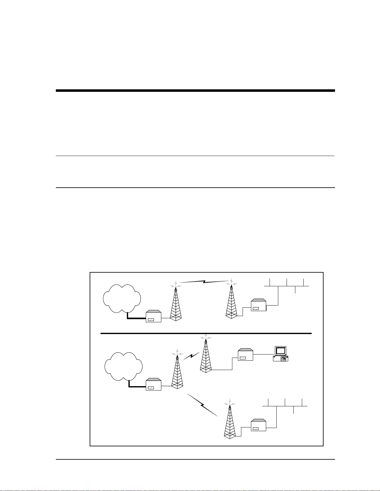
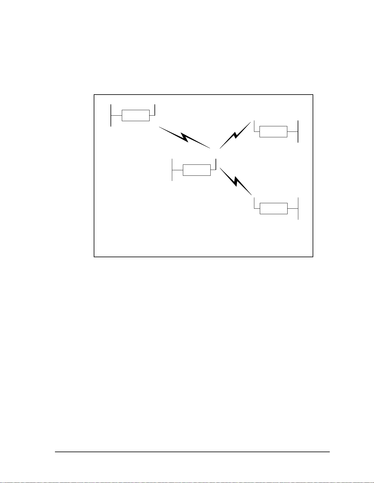
Figure 1 shows an NCL1135 point-to-point network and point-to-multipoint network.
Figure 1 NCL1135 Network Examples
Point-to-Point Network:
Network
One Master and one
Station
NCL1135
(Station)
NCL1135
(Master)
Network
Point-to-Multipoint Network:
Up to 20 Stations per Master
NCL1135
(Master)
APCD–NC003–1.0 1
NCL1135
(Station)
NCL1135
(Station)
Ethernet
Ethernet

Chapter 1 NCL1135 Overview
The NCL1135 is used to extend Ethernet networks, access the Internet at high speed, connect
remote locations, and perform general data networking without the ongoing costs of leased
telephone or data lines.
The NCL1135 provides an Ethernet interface that allows you to connect to most Ethernet
networks or devices. One NCL1135 modulates and transmits data to remote NCL1 135s, which
demodulate, decode, and pass the data to the receiving user network. DSSS signal
processing exploits the ability of transceivers to spread the signal information over a wide
channel bandwidth. This reduces the potential for interference with neighboring
communications systems. Because the NCL1135 operates in the microwave frequency range,
a line-of-sight communication link is required, therefore, some installations have the antenna
on rooftops or communications towers.
The NCL1135 is user-configurable and can be remotely upgraded. The NCL1135 operating
system supports simple network management protocol (SNMP) which allows for constant
status monitoring of any NCL1135 in your network.
All aspect s of WaveRi der’s sp re ad-s pec trum tra nsc eiv er ar e c ontr oll ed th roug h t he in tegr at ion
of a powerful microprocessor. The 2.4 GHz radio transceiver allows a single NCL1135
operating in “master” mode to deliver data to and receive data from a maximum of 20
NCL1135 devices operating in “station” mode.
The NCL1135 design permits three master units to operate in close proximity without
interfering with each other. For example, three master units each supporting 20 station units
can operate in close proximity, thus establishing 60 links.
2 APCD–NC003–1.0

1.2 Spread-Spectrum Radio Technology
Spread-spectrum communications systems differ from conventional narrowband
communications systems because these systems use a much larger transmission bandwidth
to send the same amount of information.
There are two primary forms of spread spectrum—direct sequence and frequency hopping.
The NCL1135 uses direct-sequence spread-spectrum (DSSS). In DSSS systems, the
transmitted information, along with a digital spreading sequence, are used to modulate the
transmit carrier. The received signal is de-spread using the same digital spreading sequence,
and the information recovered.
Although spread spectrum appears complex and uses a wider bandwidth, DSSS offers the
following advantages for its use:
• Reduced power spectral density — Spreading over a wider bandwidth reduces the
spectral density (power per Hz of bandwidth) of the transmitted signal, allowing
simultaneous operation of many spread spectrum systems in the same frequency
band and geographic area. The reduced spectral density also allows you meet the
regulatory emissions re qui r eme nts in freque nc y band s suc h as the ISM band.
• Transmission security — It is technologically more difficult to surreptitiously recover
(or jam, in the case of military communications systems) spread-spectrum signals
than it is to recover conventional narrowband signals.
• Interference suppression — The same mechanism that de-spreads the desired signal
in the receiver, also spreads undesired signals, which then appears to the receiver as
lower levels of RF noise.
Chapter 1 NCL1135 Overvi ew
For more information about spread spectrum communications, contact the WaveRider
Customer Support Centre.
APCD–NC003–1.0 3

— This page is intentionally left blank —

2 Network Considerations
This section provides an overview of the network considerations that you should make before
beginning to implement an NCL1135 network. These network considerations include the
following:
• network topologies
• mode: bridging and routing
• network planning
2.1 Network Topology
The NCL1135 can be deployed in three different configurations:
• point-to-point
• repeater
• point-to-multipoint
Before configuring the system, you must determine the required network topology.
APCD–NC003–1.0 5
Chapter 2 Network Considerations
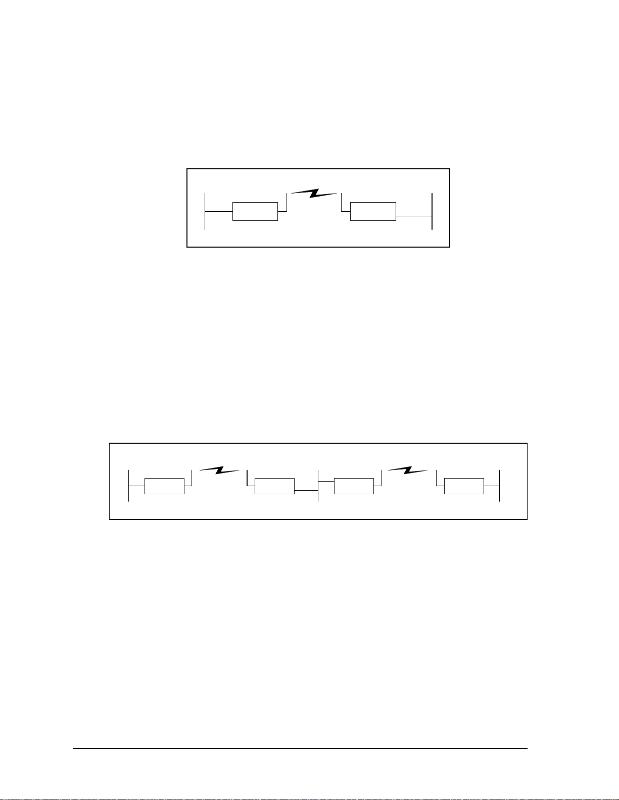
2.1.1 Point-to-Point
In a typical point-to-point application, shown in Figure 2, unit A communicates directly with unit
B. You can implement the link in either bridging or routing mode.
Ethernet EthernetRadio
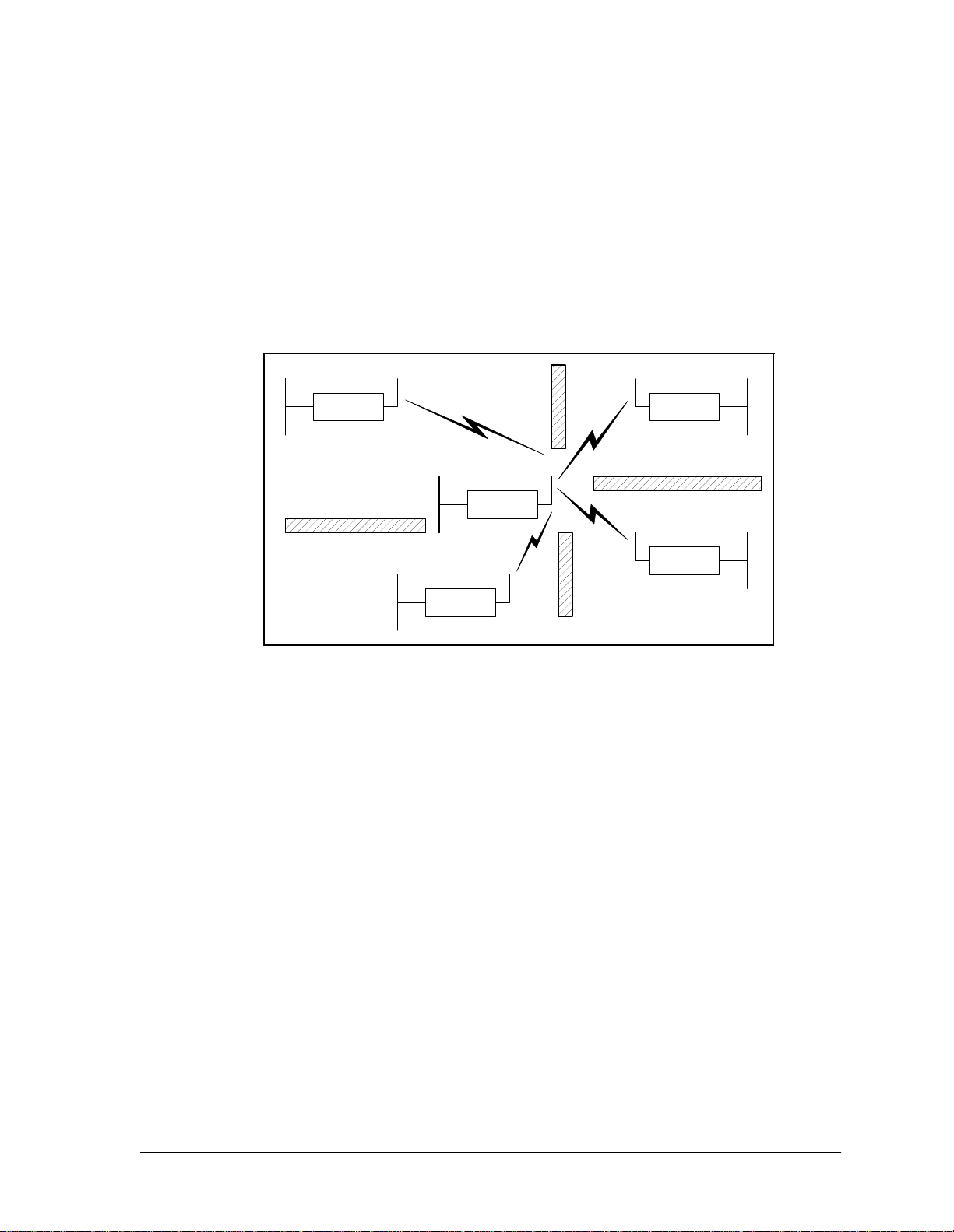
2.1.2 Repeater
You can set up a repeater by using two NCL1135 units back-to-back.
Figure 2 Point-to-Point Application
NCL1135 NCL1135
AB
In the configuration shown in Figure 3, unit A communicates with unit B via the back-to-back
NCL1135 repeater configuration of units C and D. You must use different frequencies for each
leg of the path. Use this configuration to circumvent large obstacles in the radio link path, or
when the link from unit A to unit B is too long to provide reasonable signal levels and data
throughput.
Figure 3 Repeater Application
Ethernet Radio Ethernet EthernetRadio
NCL1135
ACD
NCL1135 NCL1135 NCL1135
B
In this configuration, the effective data throughput from unit A to unit B is the same as the
lessor data throughput from unit A to unit C or unit D to unit B. That is, the throughput through
a series of links will be that of the slowest link.
You can implement this configuration in either bridging or routing mode.
6 APCD–NC003–1.0
Chapter 2 Network Considerati ons
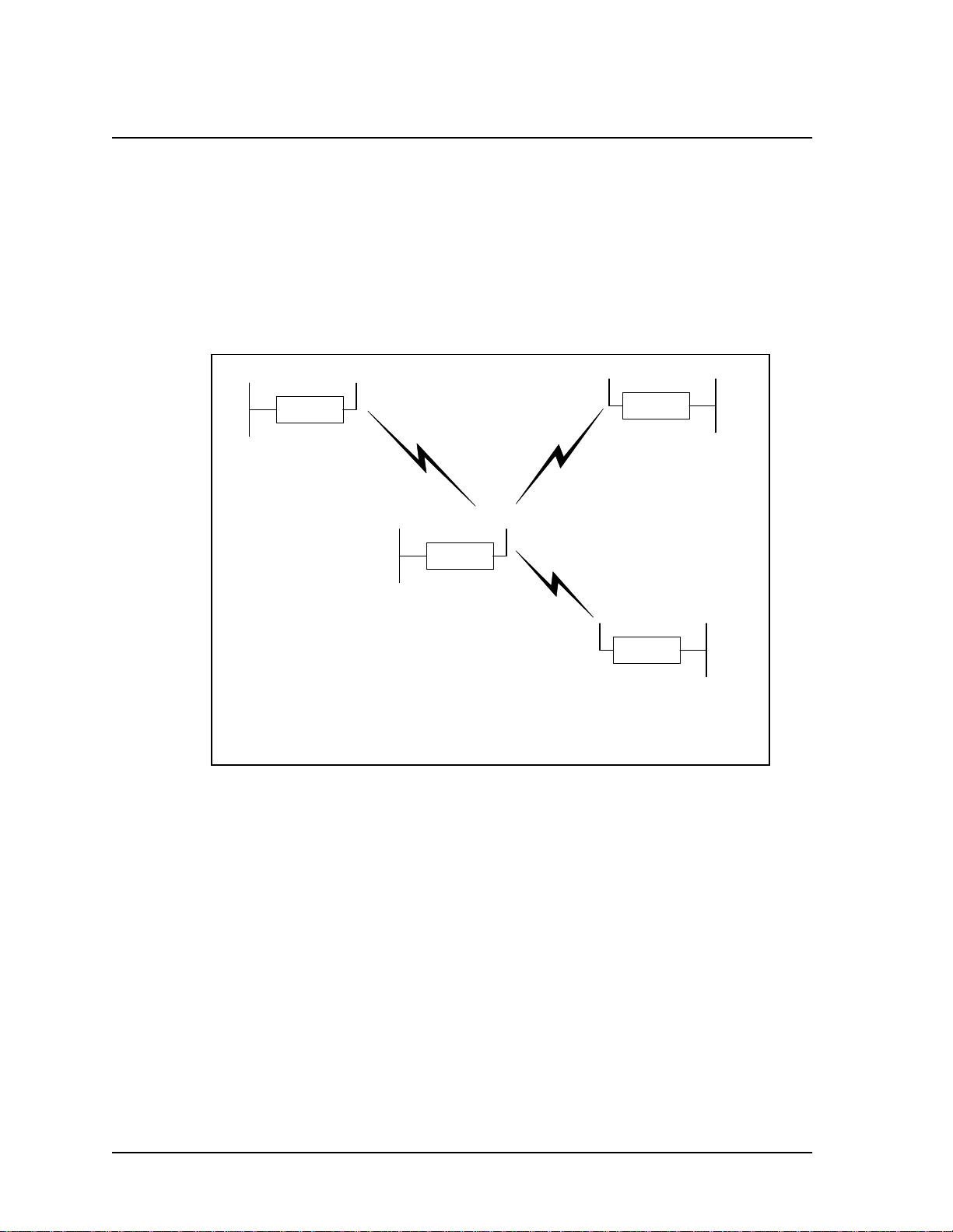
2.1.3 Point-to-Multipoint
Figure 4 shows an example point-to-multipoint configuration. The master, unit A, sends and
receives messages to and from NCL1135 stations. In this configuration, the throughput of unit
A is shared among the stations.
Although stations may receive communications from other stations, because of RF
propagation conditions, the stations are programmed to accept messages only from their
designated master.
Figure 4 Point-to-Multipoint Application
Ethernet
NCL1135
Ethernet
NCL1135
E
Ethernet
NCL1135
Ethernet
NCL1135
D
Radio
A
B
Ethernet
NCL1135
C
APCD–NC003–1.0 7
Chapter 2 Network Considerations
2.2 Bridging and Routing Network Config urations
2.2.1 Point-to-Multipoint Bridging Network
In a point-to-multipoint network configuration, all the NCL1135s in the network must be either
configured as bridges or routers, not a mix of both operational modes. Figure 5 shows the
configuration of a typical point-to-multipoint bridging network.
Figure 5 Point-to-Multipoint Bridging Network Example
Ethernet
NCL1135
D
Type: Station
Unit ID: 103
Radio Channel: 1
Mode: Bridging
IP Address - Ethernet: 10.0.2.103
Master ID: 1001
Ethernet
Radio
Type: Station
Unit ID: 101
Radio Channel: 1
Mode: Bridging
IP Address - Ethernet: 10.0.2.101
Master ID: 1001
Ethernet
NCL1135
B
NCL1135
Type: Master
Unit ID: 1001
Radio Channel: 1
Mode: Bridging
IP Address - Ethernet: 10.0.2.44
Remote Station List: 101
A
Ethernet
102
103
NCL1135
C
Type: Station
Unit ID: 102
Radio Channel: 1
Mode: Bridging
IP Address - Ethernet: 10.0.2.102
Master ID: 1001
In Figure 5, unit A is configured as the network master and units B, C, and D as stations. Units
B, C, and D unit IDs must be manually added to the Remote Station List for unit A. The Master
ID on each station is set to the unit ID for Unit A. If a unit is not in the Master Remote Station
List and does not have the Master ID set to the unit ID for unit A, it will not be able to join the
network.
8 APCD–NC003–1.0
Chapter 2 Network Considerati ons
2.2.2 Point-to-Multipoint Routing Network
Figure 6 shows the configuration of a typical point-to-multipoint routing network.
Figure 6 Point-to-Multipoint Routing Network Example
Ethernet
NCL1135
D
Type: Station
Unit ID: 103
Radio Channel: 1
Mode: Routing
IP Address - Ethernet: 13.0.2.103
Master ID: 1001
- Radio: 10.0.2.103
Ethernet
Radio
NCL1135
Type: Master
Unit ID: 1001
Radio Channel: 1
Mode: Routing
IP Address - Ethernet: 14.0.2.44
Remote Station List: 101
A
- Radio: 10.0.2.44
102
103
Ethernet
NCL1135
B
Type: Station
Unit ID: 101
Radio Channel: 1
Mode: Routing
IP Address - Ethernet: 11.0.2.101
Master ID: 1001
- Radio: 10.0.2.101
Ethernet
NCL1135
C
Type: Station
Unit ID: 102
Radio Channel: 1
Mode: Routing
IP Address - Ethernet: 12.0.2.102
Master ID: 1001
- Radio: 10.0.2.102
APCD–NC003–1.0 9
Chapter 2 Network Considerations
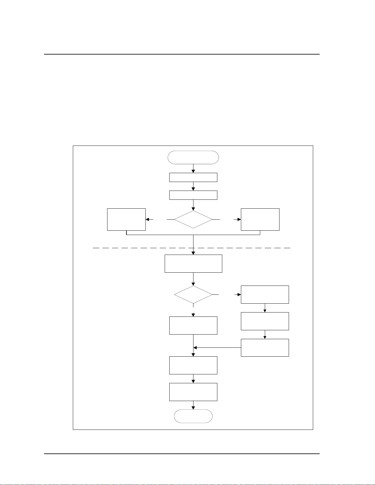
2.3 Planning an NCL1135 Configuration
Configuring each NCL1135 correctly is crucial to the proper operation of your network. Review
the flowchart in Figure 7 before starting the configuration to ensure that you have the
necessary information to configure the unit correctly.
Record your configuration options for each unit on a configuration record similar to the one
provided in Appendix E. Use the Configuration Data Record to help you plan your network and
keep track of NCL1135 network assignments.
Figure 7 NCL1135 Configuration Planning Flowchart
Start NCL1135
Configuration
Determine radio
channel
Determine unit ID
Determine station
unit IDs for
Remote Station
List
Radio Configuratio n
IP Configuration
Master or
Station?
Determine IP address and
subnet mask for Ethernet
interface
Bridging or
Routing?
Bridge
(Optional)
Determine static routes
(Optional)
Determine SNMP
configuration
(Optional)
Determine DNS server
configuration
StationMaster
Routing
Determine master
unit ID
Determine IP address
and subnet mask for
radio interface
Determine static routes
(Optional)
Determine DHCP Relay
configuration
End NCL1135
Configuration
10 APCD– NC00 3–1.0

3 Configuring the NCL1135
This section outlines the basic initialization and configuration steps for the NCL1135.
Before you begin these procedures, you should become familiar with the conventions used to
display the command-line syntax used in this manual. See
Conventions
and some typing shortcuts.
on page 55. Table 7 on p age 56 defines the command-line syntax for getting help
NOTE: The following section describes the command-line interface
protocol for configuring the NCL1135. A Windows95/98-based
application is available that provides a Graphical User Interface
for NCL1135 configuration and monitoring. For more details, refer
to the WaveRider website at
http://www.waverider.com/techsupport/index.html
NCL1135 Command-Line Syntax
.
APCD–NC003–1.0 11

Chapter 3 Configuring the NCL1135
3.1 Connecting and Initializing the NCL1135
WARNING!
Antennas and associated transmission cable must be installed
by qualified personnel. Failure to terminate the antenna port
correctly can permanently damage the NCL1135. WaveRider
assumes no liability for failure to adhere to this recommendation
or to recognized general safety precautions.
1. Attach the antenna or a 50-ohm load to the antenna connection on the back of the
NCL1135. Do NOT plug the NCL1135 to the power outlet until you have the antenna
or load connected.
NOTE: The NCL1135 is factory preset with the radio transmission
capabilities disabled to prevent equipment damage. However, as
a general precaution, WaveRider recommends that you always
connect the antenna or load before
source.
connecting to a power
Ethernet
Link LED
Power LED
Power
Supply
Figure 8 NCL1135 Connections
10BaseTx Ethernet
Connector (RJ-45)
RS-232 Connector
(DB9 consoleport)
Antenna Connector
(Reverse-Polarity SMA)
2. Use an RS-232 crossover cable to connect a terminal to the DB9 port.
12 APCD–NC003–1.0
Chapter 3 Configuring the NCL1 135
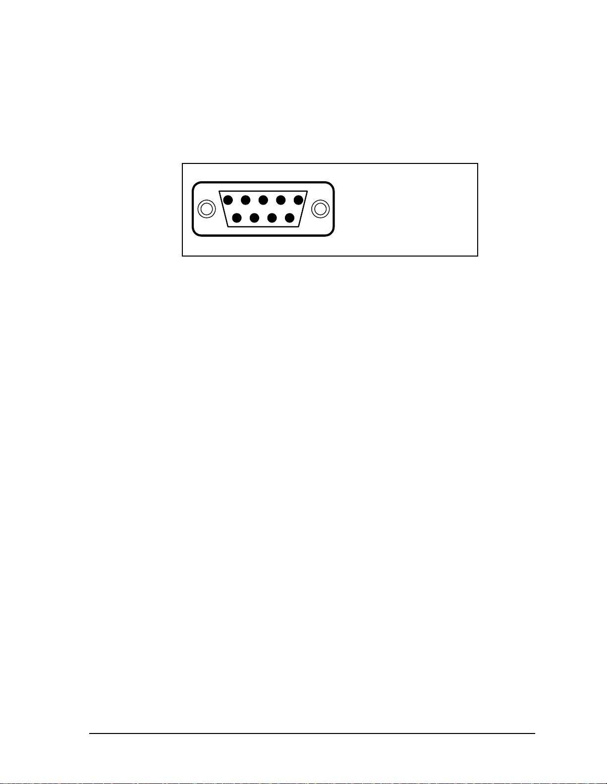
NOTE: You can use any ASCII terminal to access the NCL1135, such as
a single-function terminal or a computer running terminalemulation software. Figure 9 illustrates the pin-out for the console
port.
Figure 9 Console Port Pin-out Diagram
5
1
2
43
DB9 Male DTE Configuration
Pin 2 Rx line
Pin 3 Tx line
Pin 5 Ground
9867
3. If you are using a terminal-emulation package, such as HyperTerminal, start the
application.
4. In the terminal-emulation application, select the communications port that you are
using to connect to the NCL1135.
5. Configure the application using the following settings:
• 9600 bps
• 8 data bits
• no parity
• 1 stop bit
• no flow control
6. Plug the NCL1135 into a 110 or 220 V AC power source using the power cord
provided with the unit. The NCL1135 begins an initialization sequence displaying
progress messages on the terminal screen.
When it completes initialization, it displays a message to indicate that the system is
operational and the PASSWORD: prompt appears.
7. At the PASSWORD: prompt, press ENTER. The NCL1135 comes factory-configured
with no password.
8. Change the password for the NCL1135 by following the instructions in
NCL1135 Password
9. Change the system name in the NCL1135 as described in
System Name
, on page 14.
Setting the NCL1135
, on page 15.
Changing the
10. If the NCL1135 had been configured for use elsewhere in your network, reset the unit
by following the instructions is
Resetting an NCL1135 to Factory Settings
, on page 15.
If the NCL1135 is a factory-configured unit, you can omit this step.
The NCL1135 is now ready to be configured for your network.
APCD–NC003–1.0 13
 Loading...