

Page 1

LMS4000
900 MHz Radio Network
User Guide
APCD-LM043-4.0
Page 2

WaveRider Communications Inc.
Software License Agreement
This is a legal agreement between you (either an individual or an entity) and WaveRider Communications Inc.
for the use of WaveRider computer software, hereinafter the “LICENSED SOFTWARE”.
By using the LICENSED SOFTWARE installed in this produc t, you acknowledge that you have read this
license agreement, understand it, and agree to be bound by its terms. You further agree that it is the full
and complete agreem ent between you and WaveRider Communications Inc., superseding all prior written or verbal agreements of any kind related to the LICENSED SO FTWARE. If you do not understand or
do not agree to the ter m s of this agreement, you will cease using the LICENSED SOFTWARE immediately.
1. GRANT OF LICENSE—This License Agreement permits you to use one copy of the LICENSED
SOFTWARE.
2. COPYRIGHT—The LICENSE D SOFTWARE is owned by WaveRider Communications Inc. an d is
protected by copyright laws and internationa l treaty provisions; therefore, you must treat the LICENSED
SOFTWARE like any other copyrighted material (e.g., a book or magazine). You may not copy the written
materials accompanying the LICENSED SOFTWARE.
3. LIMITS OF FEATURE AVAILABILITY—The LICENSED SOFTWARE is sold with limitationsas to certain
feature availability and use. These limits are governed by the terms of the purchase agreement. Any
actions resulting in the exceeding of these limits is not permitted, and can result in unpredictable
performance.
4. OTHER RESTRICTIONS—You may not rent or lease the LICENSED SOFTWARE. You may not
reverse engineer, decompile, or disassemble the LICENSED SOFTWARE.
5. LIMITED WARRANTY—The LICENSED SOFTWARE is provided “as is” wit hout any warranty of any kind,
either expressed or implied, including, but not limited to, the implied warranties of merchantability and
fitness for a particular purpose. The entire risk as to the quality and performance of the LICENSED
SOFTWARE is with you, the licensee. If the LICENSED SOFTWARE is defective, you assume the risk
and liability for the entire cost of all necessary repair, service, or correction.
Some states/jurisdictions donotallow the exclusion of impliedwarranties,sothe above
exclusion may not apply to you. This warranty gives you specific legal rights, and you may
have other rights, which vary from state/ju risdiction to state/jurisdiction.
WaveRider Communications Inc.does not warrantthat the functions contained in the
LICENSED SOFTWARE will meet your requirements, or that the operation of the
LICENSED SOFTWARE will be error-free or uninterrupted.
6. NO OTH ER WARRANTIES—To the maximum extent permitted by applicable la w, WaveRider
Communications Inc.disclaimsall other warranties,eitherexpress or implied, including, but not limitedto,
the implied warranties of merchantability and fitness for a particular purpose, with regard to the
LICENSED SOFTWARE and the accompanying written materials.
7. NO LIABILI TY FOR CONSEQUENTIAL DAMAG ES—To the maximum extent permitted by applicable l aw,
in no event shall WaveRider C ommunications Inc. or its suppliers be liable for any damages whatsoever
(including, without limitation, d amages for loss of business profits, business interruption, loss of business
information, or any other pecuniary loss) arising from the use of or inability to use the LIC ENSED
SOFTWARE, even if WaveRider Communications Inc. has been advised of the possibility of such
damages, or for any claim by any other party.
Because some states/jurisdictions do not allow the exclusion or limitation of liability for
consequential or incidental damages, the above limitation may not apply to you.
In no event will WaveRider’s liability exceed the amount paid for the LICENSED
SOFTWARE.
Page 3

The following are trademarks or registered trademarks of their respective companies
or organizations:
Microsoft Windows NT 4.0 Workstation (with Service Pack 6a), Microsoft Access,
Microsoft SQL Server, Microsoft SQL Agent / Microsoft Corporation
Vircom VOP Radius Server / Vircom Inc.
Castlerock SNMPc Server / Castle Rock Computing
APS PowerChute PLUS / American Power Conversion
Veritas Backup Exec / VERITAS Software
© 2002 by WaveRider Communications Inc. All rights
reserved. This manual may not be reproduced by any means
in whole or in part without the express written permission of
WaveRider Communications Canada Inc.
ISSUE 4.0, April 2002
Page 4

Warranty
In the following warranty text, “WaveRider®” shall mean WaveRiderCommunications Inc.
This WaveRider product is warranted against defects in material and workmanship for a period of one (1)
year from the date of purchase. During this warranty period WaveRider will, at its option, either repair or
replace products that prove to be defective.
For warranty service or repair, the product must be returned to a service facility designated by WaveRider. Authorization to return products must be obtained prior to shipment. The WaveRider RMA number
must be on the shipping documentation so that the service facility will accept the product. The buyer shall
pay all shipping charges to WaveRider and WaveRider shall pay shipping charges to return the product
to the buyer within Canada or the USA. For all other countries, the buyer shall pay shipping charges as
well as duties and taxes incurred in shipping products to or from WaveRider.
WaveRider warrants that the firmware designed by it for use with the unit will execute its programming
instructionswhen properly installedon the unit. WaveRider does not warrant that the operation of the unit
or firmware will be uninterrupted or error-free.
Limitation of Warranty
The foregoing warranty shall not apply to defects resulting from improper or inadequate maintenance by
the buyer, buyer-supplied interfacing, unauthorized modification or misuse, operation outside the environmental specifications for the product, or improper site preparation or maintenance. No other warranty
is expressed or implied. WaveRider specifically disclaims the implied warranties of merchantability and
fitness for any particular purpose.
No Liability for Consequential Damages
To the maximum extent permitted by applicable law,in no event shall WaveRider or its suppliers be liable
for any damages whatsoever (including,without limitation, damages for loss of business profits,business
interruption, loss of business information, or any other pecuniary loss) arising from the use of or inability
to use the product, even if WaveRider has been advised of the possibility of such damages, or for any
claim by any other party.
Because some states/jurisdictions do not allow the exclusion or limitation of liability for consequential or
incidentaldamages, the above limitation may not apply to you.
In no event will WaveRider’s liability exceed the amount paid for the product.
Regulatory Notices
This equipment has been tested and found to comply with the limits for a Class B Intentional Radiator,
pursuant to Part 15 of the FCC Regulations and RSS-210 of the IC Regulations. These limits are
intended to provide protection against harmful interference when the equipment is operated in a residential environment.
This equipment generates, uses, and can radiate radio frequency energy and, if not installed and used in
accordance with the instruction manual, may cause harmful interference to radio communications. However, there is no guarantee that interference will not occur in a particular installation.
Notice to User
Any changes or m odifications to equipment that are not expressly approved by the manufacturer may
void the user’s authority to operate the equipment.
Page 5

Contents
Contents.................................................................v
Figures..................................................................ix
Tables...................................................................xi
Preface.................................................................xv
1 Introduction . . . . . . . . . . . . . . . . . . . . . . . . . . . . . . . . . . . . . . . . . . . . . . . . 1
2QuickStartup ...............................................5
2.1Equipment...........................................................5
2.2EquipmentSetup .....................................................6
2.3CCUConfiguration....................................................7
2.4EUMConfiguration....................................................8
2.5TestingCCU–EUMCommunications......................................9
2.6ConnectingtheQuickStartuptotheInternet...............................11
2.7AddingmoreEUMstotheQuickStartup..................................12
3DetailedDescription ........................................13
3.1LMS4000Overview...................................................13
3.2CommunicationsAccessPoint..........................................14
3.2.1KeyComponents...............................................14
3.2.2OptionalComponents ...........................................17
3.3Customer-premisesEquipment .........................................18
3.3.1KeyComponents...............................................18
3.3.2EUM ........................................................19
3.4BasicOperation .....................................................22
3.4.1LMS4000TransmissionConcept ..................................22
3.4.2CCUandEUMConfiguration .....................................22
3.4.3LMS4000ProtocolStacks........................................24
3.4.4BasicDataTransmission ........................................24
3.5 CCU–EUM Interface — Detailed Technical Description. . . . . . . . ...............28
3.5.1PhysicalLayer(DSSSRadio) .....................................28
3.5.2MACLayer(PollingMAC)........................................36
3.6CCUandEUMFeatureDescription......................................48
3.6.1DHCPRelay ..................................................48
3.6.2PortFiltering ..................................................49
3.6.3SNTP/UTCTimeClock ..........................................50
3.6.4CustomerList .................................................51
3.6.5 SNMP Support . . . . ............................................51
4IPNetworkPlanning ........................................53
4.1LMS4000IPAddressing...............................................53
4.2IPPlanningProcess..................................................55
APCD-LM043-4.0 v
Page 6

4.3NetworkAddressTranslation .......................................... 57
5RadioNetworkPlanning.....................................59
5.1DesignMethodology................................................. 59
5.2BasicSystemDesign ................................................ 60
5.2.1OverviewofBasicSystemDesign..................................60
5.2.2SpectralSurveyoftheTargetServiceArea ..........................60
5.2.3In-bandInterference ............................................61
5.2.4Out-of-bandInterference .........................................61
5.2.5UsingBandpassFiltersatCAPSites ...............................63
5.2.6Single-orMulti-CAPImplementation................................64
5.3Multi-CAPRFNetworkDesignConsiderations............................. 67
5.3.1Multi-CAPNetworkDesignProcess ................................67
5.3.2FrequencySelection—StandardFrequencySet......................67
5.3.3C/IRequirements...............................................68
5.3.4DealingwithExternalInterference..................................69
5.3.5VerifyingtheDesign ............................................69
5.3.6SummaryofRFDesignGuidelines .................................71
6 Installation/Diagnostic Tools . . . . . . . . . . . . . . . . . . . . . . . . . . . . . . . . . 73
6.1IndicatorsandConnectors ............................................ 74
6.1.1NetworkLED ..................................................75
6.1.2RadioLED ....................................................75
6.1.3PowerLED ...................................................75
6.1.4EthernetLEDs .................................................76
6.2Command-lineInterface.............................................. 76
6.3EUMConfigurationUtility ............................................. 77
6.4RSSI/TxQuality/AntennaPointing ...................................... 77
6.5TransferaFiletoorfromaCCUUsingFTP............................... 78
6.6OperatingStatistics.................................................. 79
6.7SNMP............................................................ 80
6.8FieldUpgradeProcess............................................... 80
6.9FTPingCCUandEUMConfigurationFiles................................ 81
7ConfiguringtheCCU........................................83
7.1CCUandEUMSerialNumber,MACAddress,andStationID................. 84
7.2SettingtheCCUPassword............................................ 84
7.3ConfiguringtheCCURFParameters.................................... 85
7.4ConfiguringCCUIPParameters........................................ 86
7.5 Configuring DHCP Relay. . . . . . ........................................ 88
7.6ConfiguringPortFiltering.............................................. 89
7.7ConfiguringtheSNTP/UTCTimeClock.................................. 90
7.8ConfiguringSNMP................................................... 93
7.9AddingEUMstotheAuthorizationTable ................................. 95
8ConfiguringtheEUM .......................................97
8.1SettingtheEUMPassword............................................ 98
8.2ConfiguringtheEUMRFParameters.................................... 98
8.3ConfiguringEUMIPParameters........................................ 99
8.4ConfiguringPortFiltering............................................. 101
vi APCD-LM043-4.0
Page 7

8.5ConfiguringSNMP ..................................................102
8.6ConfiguringtheCustomerList .........................................104
9 Installing the EUM . . . . . . . . . . . . . . . . . . . . . . . . . . . . . . . . . . . . . . . . . 105
9.1BeforeyouStarttheEUMInstallation....................................105
9.2OtherEUMProgrammingConsiderations ................................106
9.3InstallationOverview.................................................106
9.4InstallationProcedures...............................................107
9.4.1OpeningtheBox ..............................................107
9.4.2TurningofftheEnd-user’sCordlessPhones ........................108
9.4.3ChoosingaLocationfortheEUMandAntenna ......................108
9.4.4ConnectingtheEUMComponents ................................108
9.4.5ConductingaPreliminaryCheckoftheEUM ........................110
9.4.6PositioningtheAntenna ........................................111
9.4.7MountingtheAntenna..........................................112
9.4.8ConnectingtheEnd-user’sPC ...................................115
9.4.9ObtainingValidIPAddressesfortheEnd-user’sPC ..................116
9.4.10TestingtheDataLink .........................................116
9.4.11ConfiguringtheBrowserApplication..............................119
9.4.12CompletingtheInstallation .....................................120
9.4.13BaseliningtheInstallation ......................................120
9.4.14 Troubleshooting . . ...........................................121
10MaintainingtheNetwork ...................................125
11MonitoringtheNetwork....................................127
11.1CCUTransmitStatistics.............................................127
11.2CCUReceiveStatistics..............................................131
11.3EUMStatisticsMonitoring............................................132
11.3.1EUMTransmitStatistics .......................................132
11.3.2EUMReceiveStatistics........................................133
11.3.3UserData ..................................................134
12 Troubleshooting . . . . . . . . . . . . . . . . . . . . . . . . . . . . . . . . . . . . . . . . . 135
12.1EUMTroubleshooting...............................................136
12.2CCUTroubleshooting...............................................145
12.3IfYouHaveanInterferer.............................................149
12.4GeneralTroubleshootingInformation...................................151
13SpecializedApplications...................................155
13.1EUMThinRoute...................................................155
13.2EUMBackhaul ....................................................156
APCD-LM043-4.0 vii
Page 8

Appendix A Specifications .............................................157
Appendix B FactoryConfiguration .......................................159
Appendix C Command-LineSyntax ......................................163
Appendix D AntennaGuidelines.........................................181
Appendix E CCU/EUM Data Tables . . . . . . . . . . . . . . . ........................183
Appendix F PingCommands ...........................................197
Appendix G SNMPMIBDefinitions .......................................199
Appendix H OperatingStatistics.........................................223
Appendix I IPPlan—Example .........................................241
Appendix J AcronymsandGlossary .....................................253
Index ..................................................................261
viii APCD-LM043-4.0
Page 9

Figures
Figure1 QuickStartup—CCUConfiguration...............................6
Figure2 QuickStartup—EUMConfiguration ..............................8
Figure3 QuickStartup—PingTest(fromconsoleport) ......................9
Figure4 QuickStartup—PingTest(fromEUMEthernetport) ................10
Figure5 QuickStartup—ConnectingtotheInternet ........................11
Figure6 LMS4000System ............................................14
Figure7 CCU ......................................................15
Figure8 CCUFunctionalBlocks ........................................15
Figure9 CCUShelf ..................................................16
Figure10 RFSM .....................................................18
Figure11 EUM ......................................................19
Figure 12 WaveRider Indoor Directional Antenna with Switched-beam Diversity . . . . 20
Figure 13 WaveRider Switched-beam Diversity Antenna — Beam Patterns . . . . . . . 21
Figure14 LMS4000TransmissionConcept ................................22
Figure15 LMS4000ProtocolStacks......................................24
Figure16 AddressingofIPPackets ......................................26
Figure17 DeterminationofLowestandHighestChannel......................28
Figure18 EffectofDespreading .........................................30
Figure19 TypicalNLOSPath ...........................................32
Figure20 ExamplesofRadioPaths ......................................33
Figure21 PathLossCalculation .........................................34
Figure22 EUMStateDiagram ..........................................36
Figure 23 Net Throughput per EUM — 100 EUMs, 60 kbyte HTTP every 2 minutes . 43
Figure 24 Associated EUMs — 100 EUMs, 60 kbyte HTTP every 2 minutes . . . . . . . 44
Figure 25 Net Throughput per EUM — 300 EUMs, 60 kbyte HTTP every 2 minutes . 45
Figure 26 Associated EUMs — 300 EUMs, 60 kbyte HTTP every 2 minutes . . . . . . . 45
Figure 27 DHCP Relay . . . . ............................................49
Figure28 SNTP/GMTTimeClock........................................50
Figure29 LMS4000Subnets............................................54
Figure30 ExampleofaSpectralSweep ...................................62
Figure 31 Network Design in the Presence of Out-of-band Interference . . . . . . . . . . 63
Figure32 Corner-andCenter-illuminatedcells..............................65
Figure33 SectoredCell................................................66
APCD-LM043-4.0 ix
Page 10

Figure34 EUMLEDsandConnectors.....................................74
Figure35 CCULEDsandConnectors.....................................74
Figure36 EthernetLEDs ...............................................76
Figure37 EUMComponents ...........................................107
Figure 38 Connecting the EUM Components . . . . . . ........................109
Figure39 ConnecttheDCPowerCordtotheEUM .........................109
Figure40 ConnecttheACPowerCord ...................................110
Figure41 EUMLEDs.................................................110
Figure 42 Preliminary Orientation of the Antenna (Top View) . . . . . . . ...........111
Figure43 RearViewofAntennaBracket..................................112
Figure 44 Antenna Bracket Components . . . . . . . . . . ........................113
Figure45 MountingtheAntennaintheBracket.............................114
Figure46 ConnectingtheEnd-user’sPC .................................115
Figure47 SampleConfiguration—TestingtheDataLink.....................117
Figure48 EthernetPlug(BottomView) ...................................152
Figure49 UsinganEUMforThinRoute ..................................155
Figure50 UsinganEUMforBackhaul....................................156
Figure51 CCUMIBs .................................................203
Figure52 EUMMIBs .................................................213
x APCD-LM043-4.0
Page 11

Tables
Table1 ConsoleSettings..............................................6
Table2 QuickStartup—EUMAddresses................................12
Table3 CCUConfiguration ...........................................23
Table4 EUMConfiguration ...........................................23
Table5 End-userPCConfiguration .....................................24
Table6 LMS4000900MHzRadioNetworkChannelization...................29
Table7 TypicalRadioCoverage .......................................35
Table8 FactoryDefaultGOSConfigurationFile ...........................41
Table9 FactoryConfiguredCommunityStrings ...........................51
Table 10 Example — CCU Radio Subnet IP Addressing . . . . . . . ...............56
Table 11 Standard Frequency Set . . . . . . . . . . . ............................68
Table12 RequiredC/IRatioforMulti-CAPDesign ..........................68
Table13 SampleFrequencyPlan—Multi-CAPDesign ......................69
Table14 SummaryofRFDesignGuidelines...............................71
Table15 NetworkLED................................................75
Table16 RadioLED..................................................75
Table17 PowerLED .................................................75
Table18 EthernetLEDs...............................................76
Table19 ConsoleSettings.............................................77
Table20 FTPingConfigurationFiles .....................................81
Table21 RadioLEDStatusDisplays....................................111
Table22 AntennaMountGuidelines ....................................112
Table23 SurfaceMountingOptionsfortheAntenna ........................113
Table24 EthernetLEDStatusDisplays..................................115
Table25 TemperatureandHumidityRequirements ........................125
Table26 PossibleTransmissionOutcomes...............................128
Table27 TypicalCCUTransmitStatistics ................................129
Table28 TypicalCCUReceiveStatistic .................................131
Table29 EUMTransmitStatistics ......................................132
Table 30 Remote Troubleshooting — EUM (Service Not Available) . . . . . . . . . . . . 138
Table31 RemoteTroubleshooting—EUM(ServiceDegraded)...............139
Table32 LocalTroubleshooting—EUM(ServiceNotAvailable) ..............140
Table33 LocalTroubleshooting—EUM(ServiceDegraded).................142
APCD-LM043-4.0 xi
Page 12

Table 34 Remote Troubleshooting — CCU . . . . . . . ........................146
Table35 LocalTroubleshooting—CCU .................................147
Table36 GeneralNetworkProblems ....................................151
Table37 EthernetCablingProblems ....................................152
Table38 RadioSpecifications .........................................157
Table39 EthernetInterfaceSpecifications ...............................158
Table 40 Power Supply Specifications . . . . . . . . . . ........................158
Table41 EnvironmentalSpecifications ..................................158
Table42 CCUFactoryConfiguration ....................................159
Table43 EUMFactoryConfiguration ....................................160
Table44 Command-LineSyntaxConventions .............................164
Table45 Command-LineShortcutsandGettingHelp .......................164
Table46 CCUCommand-LineSyntax ..................................165
Table47 EUMCommand-LineSyntax ...................................174
Table 48 CCU, EUM Supported Antennas . . . . . . . . ........................181
Table49 PortFilterTableEntries.......................................184
Table50 BasicCCURoutes...........................................184
Table51 RoutingTableEntries ........................................185
Table52 RoutingTableFlags. .........................................186
Table53 ARPTableEntries ...........................................187
Table54 RegistrationTableEntries .....................................190
Table55 ARPMAPTableEntries ......................................191
Table56 CustomerTableEntries.......................................192
Table57 RSSI/RSSCross-referenceforSampleUnit(at915MHz) ............195
Table58 WindowsPingTestCommandOptions...........................197
Table59 GroupsinMIB-II.............................................199
Table 60 MIB-II Interface List Header MIB . . . . . . . . ........................200
Table61 MIB-IIInterfaceListTableMIB .................................200
Table62 WaveRiderCCUBaseMIB ....................................203
Table63 WaveRiderCCUGeneralInformationEnterpriseMIBs...............204
Table64 WaveRiderCCURadioConfigurationEnterpriseMIBs...............204
Table65 WaveRiderCCURadioStatisticsMIB............................205
Table66 WaveRiderCCURadioGeneralStatisticsGroupMIB ...............205
Table67 WaveRiderCCURadioDriverStatisticsGroupMIB .................205
Table68 WaveRiderCCURadioMACStatisticsGroupMIB..................206
Table69 WaveRiderCCUEthernetStatisticsGroupMIB ....................210
Table70 WaveRiderCCUModemInformationMIB.........................211
Table71 WaveRiderCCURegistrationInformationMIB .....................211
xii APCD-LM043-4.0
Page 13

Table72 WaveRiderCCURegistrationTableMIB .........................211
Table73 WaveRiderCCUAuthorizationTableMIB ........................212
Table74 WaveRiderCCUAuthorizationTableMIB ........................212
Table75 CCURFCMIB-IITraps .......................................212
Table76 WaveRiderEUMBaseMIB....................................213
Table77 WaveRiderEUMGeneralInformationEnterpriseMIBs ..............214
Table78 WaveRiderEUMRadioConfigurationEnterpriseMIBs ..............214
Table79 WaveRiderEUMRadioStatisticsMIB ...........................215
Table80 WaveRiderEUMRadioGeneralStatisticsGroupMIB ...............215
Table81 WaveRiderEUMRadioDriverStatisticsGroupMIB.................215
Table82 WaveRiderEUMRadioMACStatisticsGroupMIB .................216
Table83 WaveRiderCCUEthernetStatisticsGroupMIB ....................219
Table84 EUMRFCMIB-IITraps.......................................221
Table85 EthernetStatistics ...........................................224
Table86 RadioDriverStatistics........................................226
Table87 MACInterfaceStatistics ......................................228
Table88 Routing/BridgingProtocolStatistics .............................233
Table89 NetworkInterfaceStatistics....................................236
Table90 LoadStatistics(RadioMeter) ..................................239
Table91 Example-CCUEthernetSubnetData ...........................241
Table92 Example-NAPIPAddressingPlan .............................241
Table93 Example-CCUEthernetIPAddressingPlan......................242
Table94 Example-CCURadioSubnetData .............................243
Table95 Example-CCURadioIPAddressingPlan ........................243
Table96 Example-EUMSubnetData ..................................245
Table97 Example-EUMIPAddressingPlan .............................245
Table98 Example-SubscriberSubnetData..............................248
Table99 Example-SubscriberIPAddressingPlan ........................248
Table100 AcronymsandAbbreviations ..................................253
Table101 LMS4000NetworkGlossary ...................................256
APCD-LM043-4.0 xiii
Page 14

— This page is intentionally left blank —
Page 15

Preface
About this Manual
WaveRider recommends that you read the following sections before proceeding with the
instructions in this guide:
• Software License Agreement on page ii
• Warranty on page iv
• Warnings and Advisories on page xvii
• Conventions on page xv
NOTE: The information contained in this manual is subject to change
without notice. The reader should consult the WaveRider web
site for updates.
The procedures in this document are centered around the command-line interface (CLI). For
information about configuring and operating the CCU and EUM using the WaveRider
Configuration Utility refer to the CCU/EUM Configuration Utility User Guide (APCD-LM030).
Conventions
The following conventions are used throughout this document:
WARNING!
Whenever you see this icon and heading, the associated text
addresses or discusses a critical safety or regulatory issue.
CAUTION: Whenever you see this icon and heading, the
associated text discusses an issue, which, if not followed, could
result in damage to, or improper use of, the equipment or
software.
TIP: Whenever you see this icon and heading, the associated
text provides a tip for facilitating the installation, testing, or
operation of the equipment or software
APCD-LM043-4.0 xv
Page 16

Regulatory Notices
This device has been designed to operate with several different antenna types. The gain of
each antenna type shall not exceed the maximum antenna system gain as given in Appendix
Donpage181. Antennas having a higher gain are strictly prohibited by Industry Canada and
FCC regulations. The required antenna impedance is 50 ohms.
Industry Canada
CCU and EUM
The IC Certification Number for the CCU and EUM is 3225104140A.
Operators must be familiar with IC RSS-210 and RSS-102. The CCU and EUM have
been designed and manufactured to comply with IC RSS-210 and RSS-102.
Federal Communications Commission
CCU and EUM
The CCU and EUM have been designed and manufactured to comply with
FCC Part 15.
Operators must be familiar with the requirements of the FCC Part 15 Regulations prior
to operating any link using this equipment. For installations outside the United States,
contact local authorities for applicable regulations.
The FCC ID for the CCU and EUM equipment is OOX-LMS3000.
The transmitter of this device complies with Part 15.247 of the FCC Rules.
The CCU and EUM (with outdoor antenna only) must be professionally installed.
Interference Environment
Operation is subject to the following conditions:
• This device may not cause harmful interference and,
• This device must accept any interference received, including interference that
might cause undesired operation.
xvi APCD-LM043-4.0
Page 17

Operational Requirements
CCU and EUM
In accordance with the FCC Part 15 regulations:
1. The maximum peak power output of the intentional radiator shall not exceed
one (1) watt for all spread spectrum systems operating in the 902 to 928MHz
band. This power is measured at the antenna port of the CCU or the EUM.
2. Stations operating in the 902 to 928MHz band may use transmitting antennas
of directional gain greater than 6dBi, provided the peak output power from the
intentional radiator is reduced by the amount in dB that the directional gain of
the antenna exceeds 6dBi.
NOTE: The gains referred to in point 2 are with respect to the total
antenna system gain.
3. The operator of a spread spectrum system and the user of the radio device
are each responsible for ensuring that the system is operated in the manner
outlined in InterferenceEnvironment on page xvi.
Warnings and Advisories
General Advisory
Operator and maintenance personnel must be familiar with the related safety requirements
before they attempt to install or operate the LMS4000 equipment.
It is the responsibility of the operator to ensure that the public is not exposed to excessive
Radio Frequency (RF) levels. The applicable regulations can be obtained from local
authorities.
Do not operate the CCU or EUM without connecting a 50-ohm termination to the antenna port.
This termination can be a 50-ohm antenna or a 50-ohm resistive load capable of absorbing the
full RF output power of the transceiver.
WARNING!
The LMS4000 external antennas must be professionally
installed and properly grounded. Antennas and associated
transmission cable must be installed by qualified personnel.
WaveRider assumes no liability for failure to adhere to this
recommendation or to recognized general safety precautions.
APCD-LM043-4.0 xvii
Page 18

WARNING!
To comply with FCC RF exposure limits, the antennas for the
CCU must be fix-mounted on outdoor permanent structures to
provide a separation distance of 2m or more from all persons
to satisfy RF exposure requirements. The distance is
measured from the front of the antenna to the human body. It
is recommended that the antenna be installed in a location
with minimal pathway disruption by nearby per sonnel.
The antennas for the EUM must be fix-mounted, indoors or
outdoors, to provide a separation distance of 20cm or more
from all persons to satisfy RF exposure requirements. The
distance is measured from the front of the antenna to the
human body. Again, it is recommended that the antenna be
installed in a location with minima l pathway disruption by
nearby personnel.
CAUTION: There is a DC signal of 5-7.5V (current limited to
5mA) on the Antenna Output of the EUM. Antennas or RF test
equipment must be able to accept this DC signal or have a device
to block the DC signal. Otherwise, the antenna, test equipment,
and/or the EUM may be damaged.
Customer Support
If you have any problems with the instructions in this manual, please contact WaveRider
Communications Inc.
Telephone: +1 416–502–3161
Fax: +1 416–502–2968
Email: Customer Services Group:
techsupport@waverider.com
Customer Documentation Feedback and Comments:
customerdocs@waverider.com
URL: www.waverider.com
WaveRider offers a complete training program. Please contact your sales representative for
traininginformation.
xviii APCD-LM043-4.0
Page 19

1 Introduction
The LMS4000 system provides 900MHz and 2.4GHz wireless. high-speed Internet
connectivity to business and residential subscribers. This manual, which is specific to the
LMS4000 900MHz Radio Network, provides the following information:
• A detailed description of the operation of the hardware and software
• Guidelines for planning and designing your network
• Instructions for configuring, installing the 900MHz radio modem, monitoring,
maintaining and troubleshooting
• Support information that you may find useful for operating your network
TIP: The installation of other LMS4000 network equipment is
described in LMS4000 Installation Guide, which can be obtained
from WaveRider.
The LMS4000 900MHz Radio Network, which operates in the 900MHz ISM band, offers the
following features and benefits:
• Excellent Propagation Characteristics: LMS4000 900MHz radio networks provide
excellent coverage to non-line of sight installations using WaveRider’s proprietary
indoor diversity antenna and extended coverage to installations using external highgain antennas.The 900MHz ISM band is more suited to NLOS (non-line of sight)
wireless Internet applications than other ISM bands because it has superior
propagation performance, demonstrating the following benefits:
• Lower free-space, cable and foliage loss
• Better wall and glass penetration
• More signal recovery from diffraction and reflection
• High-speed Channel: The LMS4000 900MHz Radio Network provides a raw channel
bit rate of 2.75Mbps, which translates to peak FTP rates of 2Mbps.
• High-performance Polling MAC: WaveRider’s patented Polling MAC algorithm
takes advantage of typical usage patterns found in Internet transactions, such as Web
browsing and email, to provide an operating capacity of up to 300 end users per RF
APCD-LM043-4.0 1
Page 20

1 Introduction
channel. Even with large numbers of subscribers, end users generally perceive that
they have the entire channel to themselves.
• Grade of Service Support: The Polling MAC supports up to four end-user grades of
service, which allows the system operator to segment service offerings for those users
that demand and are willing to pay for higher grades of service, and those that are
only willing to pay for a more basic grade of service.
• License-free Radio Bands: The main advantage of using the ISM band is that you
need not apply to the FCC or Industry Canada for an operating license. This freedom
reduces your time to market and the effort and high cost associated with obtaining a
license.
• Robust Hardware and Software: LMS4000 hardware and software have been
rigorously tested in lab and field environments. The hardware, which is mechanically
robust, works over a broad range of temperatures and operating conditions. The
software is equally robust and has been designed to recover automatically from
unplanned events and abnormal operating conditions.
• Simple End-user Modem Configuration: The end-user modem is very easy to
configure. Normally, operators pre-configure the EUM prior to field deployment, so
they can maintain control over their network.
• Simple End-user Modem Installation and Operation: It is very easy to install and
operate the EUM. So easy, in fact, that when the installation is based on the
WaveRider indoor diversity antenna, the end user should be able to install and
operate the modem with no involvement from the network operator. This simplicity
saves the network operator the cost and inconvenience of having to visit the enduser’s premises. The EUM uses a standard Ethernet interface which means the EUM
and the antenna can be located up to 100m from the end-user’s PC.
• Flexible Network Topology: The LMS4000 900MHz Radio Network has a flexible
topology, allowing it to line up with the operator’s existing Internet points of presence
and site facilities. As well, LMS4000 supports the following connections:
• Connection between the end-user modem and the Internet through the
network operator’s gateway router
• Direct connection between end-user modems through the LMS4000 900MHz
channel units (CCUs), if the CCU is configured to support this routing
• Connection between end-user modems on different, but colocated, CCUs if
these routes are configured in the CCU routing tables
• DHCP Relay: CCUs support DHCP relay, which, once enabled, allows end-user PCs
to automatically obtain their IP and DNS server addresses from the network operator’s
DHCP servers. DHCP relay simplifies the EUM installation even further and makes it
even easier for the modem to be installed by the end user.
• End-user Registration: All end user modems automatically transmit a registration
request to the LMS4000 system so they can access the wireless network. They can
only register if the network operator has authorized them in the CCU. This registration
guarantees that only approved subscribers can gain access to LMS4000 wireless
services.
• Remote System Configuration and Diagnostics: The network operator can
configure and monitor CCUs and EUMs from anywhere. This remote access allows
the operator to make configuration changes, download new features, and diagnose
problems remotely without having to visit distant network sites or end-user premises.
2 APCD-LM043-4.0
Page 21

1 Introduction
• SNMP Support: Using WaveRider-supplied SNMP MIBs, network operators can
integrate the LMS4000 with their existing network management system to allow
monitoring of CCUs and EUMs from an existing and/or centralized SNMP manager.
Once SNMP is configured, the operator can monitor system events, parameters, and
statistics in real time. Statistics can be processed in the SNMP manager to provide
alarms, trend data, graphical outputs, and derived performance data.
• Channel Redundancy (optional): Optional CCU redundancy, which can be ordered
from WaveRider, improves LMS4000 system reliability, and reduces or eliminates
down time if a CCU fails. This redundancy eliminates interruption of service to the end
users and reduces the urgency for getting to the CCU site to replace the failed CCU.
• Accurate Time Stamping (SNTP): The CCUs and EUMs can be programmed to
synchronize their internal clocks with one or more NTP servers. Time stamping
enables all logged events in the CCUs and EUMs to be correlated with events that
have taken place at other locations in the network or with events logged by equipment
installed outside the network, if this equipment is equipped with accurate timestamping. Accurate time-stamping facilitates diagnosis of complex network problems.
• Field-replaceable Equipment: In the event of an equipment failure, LMS4000
components are easily replaced with minimal or no disruption to the operation of other
components.
• System Upgradability: The LMS4000 network architecture supports orderly growth
from simple installations, through single-CCU CAP (Communication Access Point)
sites and multi-CCU CAP sites, to multi-CAP networks.
• Port Filtering: The LMS4000 network operator can configure CCUs and EUMs to
filter IP packets on specific TCP and UDP ports to improve network performance,
security, and privacy.
• Low Maintenance: CCUs and EUMs require no routine maintenance, other than
maintenance of their operating environments within the specified temperature and
humidity range.
• Extensive Installation, Maintenance and Diagnostic Support: TheCCUandEUM
are equipped with a wide range of features and utilities to facilitate unit installation,
operation, maintenance, monitoring, and diagnostics:
• Visual status indicators on all units
• Simple-to-use command-line interface, offering full unit configuration
capability
• Windows-based EUM configuration and installation utilities
• RSSI (receive signal strength indication) output, to simplify antenna pointing
and performance measurement
• Ability to remotely FTP files to and from CCUs and EUMs
• Wide range of operating and performance statistics
• SNMP support
• Simple and reliable field-upgrade process
• Remote download of equipment configuration files to CCUs and EUMs
Your decision to implement an LMS4000 900MHz Radio Network enables you to deliver highquality, high-speed wireless Internet service to the business and residential subscribers in
your serving area.
APCD-LM043-4.0 3
Page 22

— This page is intentionally left blank —
Page 23

2 Quick Startup
This section outlines the procedure for setting up a very simple LMS4000 900 MHz radio
network consisting of one CCU and one EUM. This simple network, which can be set up in a
lab environment, helps you become familiar with basic LMS4000 configuration and operation.
As you become more confident and are ready to progress to customer installations,
WaveRider recommends you read the other sections in the manual.
Quick Startup uses static IP addresses for the purpose of simplicity,even though the CCU and
EUM support DHCP relay.
2.1 Equipment
As a minimum, the Quick Startup requires the following equipment:
one CCU kit, consisting of
• CCU
• CCU power supply and cable
• CCU setup antenna
one EUM kit, consisting of
•EUM
• EUM power supply and cable
• 3m CAT5 crossover Ethernet cable
one PC, equipped with terminal emulation software such as HyperTerminal and an
Ethernet network interface card
one WaveRider indoor antenna, complete with mounting bracket and RF cable
one Straight-through RS-232 serial cable, DB-9 male to DB-9 female
APCD-LM043-4.0 5
Page 24
2 Quick Startup
2.2 Equipment Setup
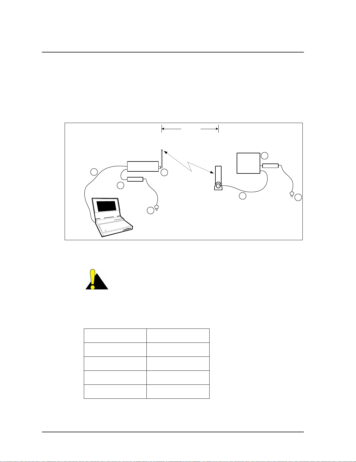
1. Remove the equipmentfrom the boxes and set up the physicalconfigurationshown in
Figure 1. Use this setup procedure to configure the CCU, while keeping the following
points in mind:
• Maintain the order of installation shown in Figure 1.
• Maintain at least 3 to 5 meters of physical separation between CCUs and
EUMs.
• Ensure the paths between the CCU and EUMs are relatively free from
obstruction.
RS232 cable
4
CCU power
2
supply
CCU3000
CCU set-up
antenna
3-5metres
Radio
Link
1
EUM Antenna
EUM3000
5
6
EUM Power Supply
7
3
Figure 1 Quick Startup — CCU Configuration
CAUTION: Always make sure that you connect the antenna to
the CCU or EUM before you apply power to the unit.
2. Configure your PC terminal emulation software as shown in Table 1.
Table 1 Console Settings
Bits per second 9600
Data bits 8
Parity None
Stop bits 1
Flow Control None
6 APCD-LM043-4.0
Page 25

2.3 CCU Configuration
1. Start the PC terminal emulation software. You will receive the following prompt:
WaveRider Communications, Inc. LMS3000
Password:
The default password is a carriage return.
Console>
The default prompt on your CCU is the CCU Ethernet MAC address.
2. Type the following commands to configure the CCU:
Console> ip ethernet 192.168.10.10 24
Console> ip radio 10.0.0.1 22
Console> ip gateway 192.168.10.1
Console> radio frequency 9150
Console>
Console> save
Basic Config saved
Port Filter Config saved
sntp cfg file saved
Route Config saved
Authorization Database saved
DHCP Server Config saved
2QuickStartup
3. Reboot the CCU for the changes to take effect.
Console> reset
rebooting CCU ...
(... Power On Self Test ...)
WaveRider Communications, Inc. LMS3000
Password:
TIP: If you want to connect the Quick Setup to the Internet as
outlined in Connecting the Quick Startup to the Internet on page
11, obtain the CCU gateway IP address from your network
administrator. You can then set the CCU Ethernet IP address to
any IP address in the subnet.
4. Confirm the CCU has been properly configured, as follows:
Console> ip
Ethernet IP Address: 192.168.10.10
Ethernet Net Mask : ffffff00
Gateway IP Address: 192.168.10.1
Radio IP Address: 10.0.0.1
Radio Net Mask : fffffc00
Console> radio
RF Power: HIGH
Radio Frequency: 9150
Console>
APCD-LM043-4.0 7
Page 26
2 Quick Startup
2.4 EUM Configuration
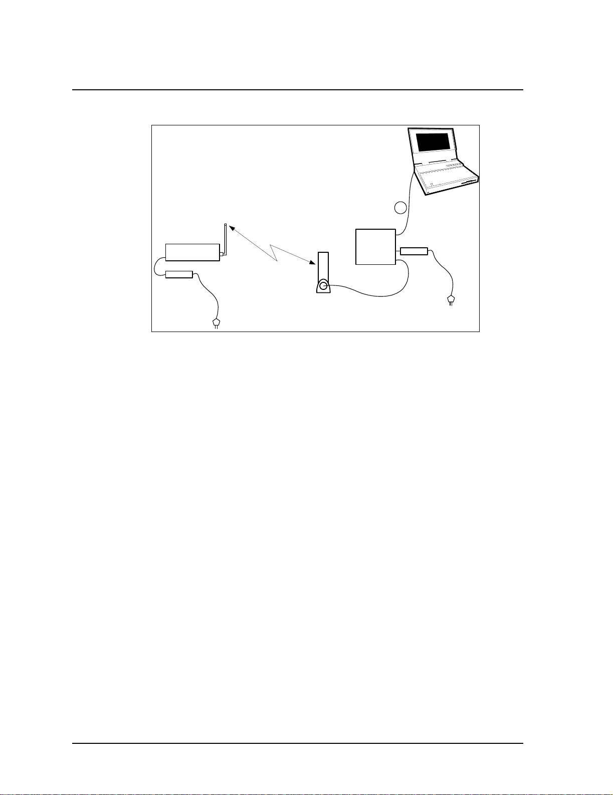
1. Connect the PC to the console port of the EUM, as shown in Figure 2.
CCU set-up
CCU3000
CCU power
supply
antenna
Radio
Link
EUM3000
EUM Antenna
Figure 2 Quick Startup — EUM Configuration
2. Start the terminal emulation software.
3. Type the following commands to configure the EUM:
WaveRider Communications, Inc. LMS3000
Password:
Console> ip ethernet 10.0.0.2 22
Console> ip gateway 10.0.0.1
Console>
Console> radio frequency 9150
Console>
Console> save
Basic Config saved
Port Filter Config saved
sntp cfg file saved
Console>
1
RS232 cable
EUM Power Supply
4. Reboot the EUM for the settings to take effect.
Console> reset
rebooting EUM ...
(... Power On Self Test ...)
WaveRider Communications, Inc. LMS3000
Password:
8 APCD-LM043-4.0
Page 27
5. Confirm that the EUM has been properly configured, as follows:
Console> ip
Ethernet/USB IP Address: 10.0.0.2
Ethernet/USB Net Mask : fffffc00
Gateway IP Address: 10.0.0.1
Console> radio
RF Power: HIGH
Radio Frequency: 9150
Console>
2.5 Testing CCU–EUM Communications
Once you have completed the configuration of the Quick Startup, you can test
communications between the CCU and the EUM by pinging the CCU through the EUM
console port.
To Run a Ping Test Through the EUM Console Port
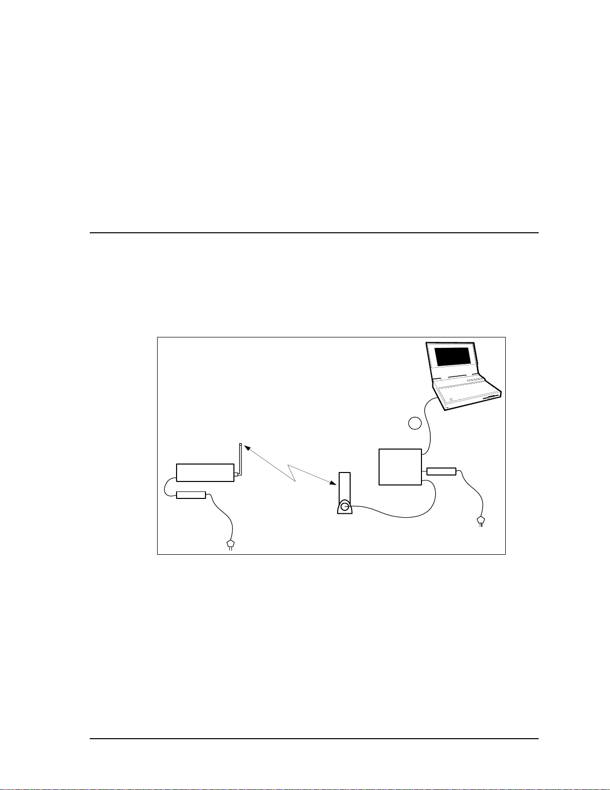
1. Connect the PC to the EUM console port, as shown in Figure 3.
2QuickStartup
1
RS232 cable
EUM Power Supply
CCU3000
CCU power
supply
CCU se t-up
antenna
Radio
Link
EUM3000
EUM Antenna
Figure 3 Quick Startup — Ping Test (from console port)
2. From the EUM, ping the CCU radio port (IP address 10.0.0.1), as follows. Press any
key to stop.
console>
console> ping 10.0.0.1
Press any key to stop
PING 10.0.0.1: 56 data bytes
64 bytes from 10.0.0.1: icmp_seq=1. time=112. ms
64 bytes from 10.0.0.1: icmp_seq=2. time=48. ms
64 bytes from 10.0.0.1: icmp_seq=3. time=48. ms
64 bytes from 10.0.0.1: icmp_seq=4. time=32. ms
64 bytes from 10.0.0.1: icmp_seq=5. time=32. ms
APCD-LM043-4.0 9
Page 28
2 Quick Startup
To Run a Ping Test Through the EUM Ethernet Port
64 bytes from 10.0.0.1: icmp_seq=6. time=16. ms
64 bytes from 10.0.0.1: icmp_seq=7. time=64. ms
64 bytes from 10.0.0.1: icmp_seq=8. time=64. ms
----10.0.0.1 PING Statistics---8 packets transmitted, 8 packets received, 0% packet loss
round-trip (ms) min/avg/max = 16/52/112
console>
This test verifies the radio link between the EUM and the CCU.
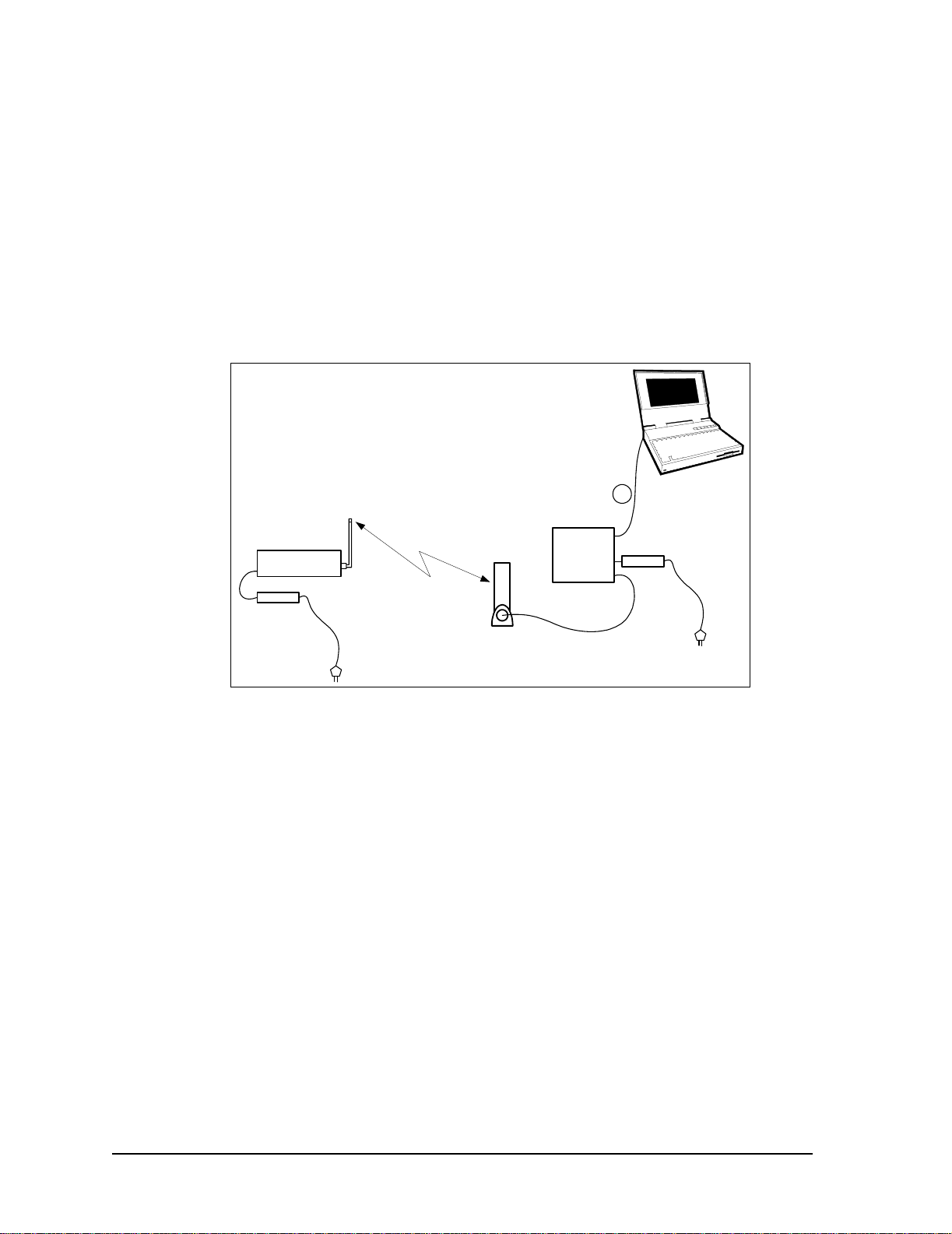
1. Connect the PC to the EUM Ethernet port, as shown in Figure 4.
1
Ethernet crossover
EUM Power Supply
cable
CCU3000
CCU power
supply
CCU set-up
antenna
Radio
Link
EUM3000
EUM Antenna
Figure 4 Quick Startup — Ping Test (from EUM Ethernet port)
2. Open the TCP/IP Properties window in the PC. If you are not sure how, consult your
operating system manual.
3. Select Use the following IP address (or Specify an IP address—the exact wording
depends on your operating system). Enter the following:
• IP Address 10.0.1.2
• Subnet Mask 255.255.252.0
• Default Gateway10.0.0.1
4. From the PC, progressively ping the PC Ethernet port (10.0.1.2), the EUM (10.0.0.2),
and the CCU radio (10.0.0.1) and Ethernet (192.168.10.10) ports.
10 APCD-LM043-4.0
Page 29
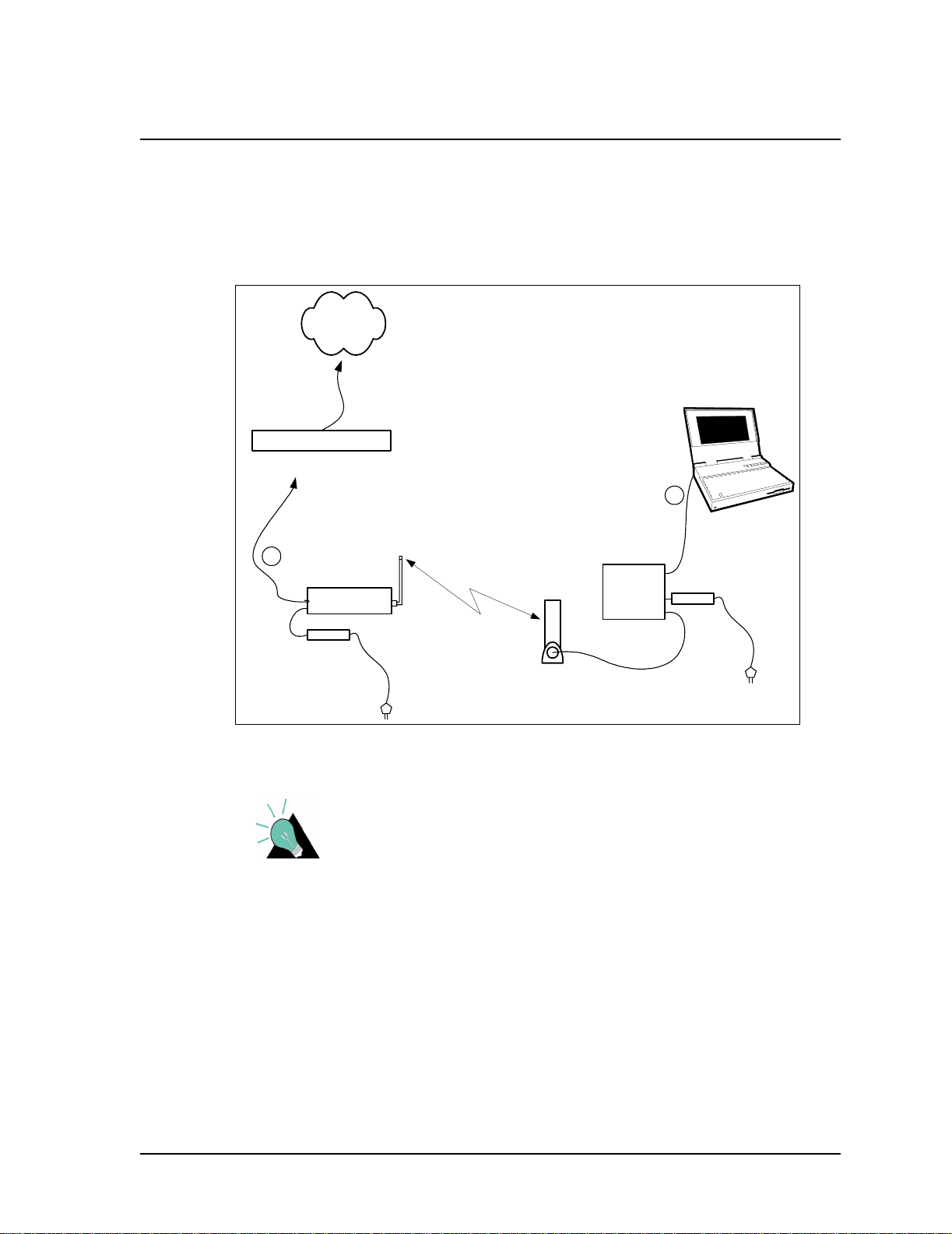
2.6 Connecting the Quick Startup to the Internet
Once you have verified that the CCU and EUM are communicating properly, you may want to
to connect the Quick Startup system to the Internet.
To Connect to the Internet
1. Connect the PC to the Ethernet port of the EUM as shown in Figure 5.
Internet
Gateway Router
2QuickStartup
1
cable
EUM Power Supply
2
CCU3000
CCU power
supply
CCU set-up
antenna
Radio
Link
Ethernet crossover
EUM3000
EUM Antenna
Figure 5 Quick Startup — Connecting to the Internet
TIP: If you want to connect the Quick Setup to the Internet, you
must obtain the CCU gateway IP address from your network
administrator. The CCU Ethernet IP address can then be set to
any IP address in the subnet.
2. If you have not already configured the PC IP address as outlined in Testing CCU–
EUM Communications on page 9, open the TCP/IP Properties window in the PC. If
you are not sure how, consult your operating system manual.
3. Select Use the following IP address (or Specify an IP address; the exact wording
depends on the operating system), and enter the following:
• IP Address 10.0.1.2
• Subnet Mask 255.255.252.0
• Default Gateway10.0.0.1
APCD-LM043-4.0 11
Page 30

2 Quick Startup
4. Select Use the following DNS server address (the exact wording depends on your
operating system), and enter the IP address for the Preferred DNS Server, which is
available from your Network Administrator.
5. Connect the CCU Ethernet port to the appropriate network switch or hub, or directly to
the gateway router of your network.
6. From the PC, you should now be able to open your browser and surf the Web.
2.7 Adding more EUMs to the Quick Startup
You can add other EUMs and PCs to the Quick Startup system. At all times, try to maintain at
least 3 to 5 m (10 to 15 ft.) separation between the EUMs, and between the EUMs and the
CCU.
Other EUMs are added in the same way as the first EUM, using the same gateway IP address
(10.0.0.1), subnet masks (255.255.252.0), and the following EUM and PC IP addresses:
Table 2 Quick Startup — EUM Addresses
EUM
Number
2 10.0.0.3 10.0.1.3
3 10.0.0.4 10.0.1.4
4 10.0.0.5 10.0.1.5
5 10.0.0.6 10.0.1.6
6 10.0.0.7 10.0.1.7
EUM IP Address PC IP Address
12 APCD-LM043-4.0
Page 31

3 Detailed Description
This section describes the technologies and features used in the LMS4000 900 MHz Radio
Network.
3.1 LMS4000 Overview
Figure 6 is a high-level schematic of the LMS4000 system, showing the key system
components and interfaces.
As shown, each LMS4000 component is associated with one of three major system entities:
• End-user Modem (EUM)
• Communications Access Point (CAP)
• Network Access Point (NAP)
End-user Modem or Customer-premises Equipment
The EUM equipment is installed at the end-user’s premises. It provides an interface to the
customer’s computer or local area network on one side and wireless access to the LMS4000
network on the other.
Communications Access Point (CAP)
The CAP is the collection and distribution point for data travelling to and from the EUMs. In the
EUM-to-network direction, the CAP aggregates the data from the radio channels into a single
data stream, which is passed either directly or over a backhaul facility to the Network Access
Point.
In the Internet-to-EUM direction, the CAP receives data from the Network Access Point and
distributes this data to the appropriate radio channels for transmission to the EUMs over the
900 MHz radio link.
APCD-LM043-4.0 13
Page 32

3 Detailed Description
Network Access Point (NAP)
The NAP provides the Internet connection point for one or more CAPs. An LMS4000 system
can have more than one NAP. The number of NAPs depends on the geographical layout of
the LMS4000 system and the location of available Internet access points. A single NAP can
provide Internet connection for one CAP, or several CAPs, each either colocated with the NAP
or connected to the NAP over backhaul facilities.
Internet
NMS Station
Router
-Subscriber
Management
-BillingData
- Authorization
- Registration
Networkand
Equipment
Management
NAP
EUM
End-user PC
To Other
CAPs
Routing to/from
Layer 3
-Switching
- Routing
10/100BaseT
Internet
Switch
Radio Control
- Configuration
- Redundancy
Backhaul (NCL1170,
for example)
10BaseT
CCU
CCU
CCU
Back-up CCU
UPS
Not part of
LMS4000
RFSM
Figure 6 LMS4000 System
The following sections discuss the operation of the LMS4000 900 MHz Radio Network, of
which the CCU and EUM are the key components.
3.2 Communications Access Point
CAP
Antenna
Cavity Filters
Antenna
Antenna
EUM
- Authorization
- Registration
EUM
EUM
End-user PC
End-user PC
3.2.1 Key Components
The following are key components of the Communication Access Point:
• CCU
•Cavityfilters
• Lightning arrestors
14 APCD-LM043-4.0
Page 33

3 DetailedDescription
• Transmission line
• Antenna
• Ethernet switch
Each of the above components is discussed in the following sections.
CCU
The CCU, shown in Figure 7, is the wireless access point for up to 300 end-user modems. The
functional blocks of the CCU are illustrated in Figure 8.
Ethernet Port
10 BaseT
Console Port
DB9, RS232
Baseband
Co n trolle r
Baseband
Figure 7 C CU
Media
Access
Controller
Radio
Baseband
Processor
Radio
Power
Up/Down
Converter
Figure 8 CCU Functional Blocks
Power
Amplifier/
Low-noise
Amplifier
CCU3000
Antenna
7.5 VDC
APCD-LM043-4.0 15
Page 34

3 Detailed Description
The CCU routes IP packets received from the CCU radio port
• to internal CCU processes,
• through the CCU Ethernet port to any router on the Ethernet network, such as the
Network Access Point, or
• back out the radio port to other EUMs (EUM-to-EUM packets).
The CCU routes IP packets that are received from the Network Access Point through the
Ethernet port
• to internal CCU processes, or
• through the radio port to the destination EUM.
The CCU can be installed in a standalone configuration, or in a CCU shelf, as shown in Figure
9, with other operating and backup CCUs. The CCU is powered by an AC/DC power supply,
which can also stand alone or be installed in the CCU shelf. The CCU operates independently
of other CCUs and can be swapped out without interrupting the operation of other CCUs.
Figure 9 CCU Shelf
Up to four CCUs can be installed at the same CAP, as follows:
• Up to three operating CCUs, each with its own cavity filter, lightning protector,
transmission line, and antenna.
• One backup CCU, if CCU redundancy is provisioned. Since the backup CCU is
“switched” into the RF circuit of the failed CCU, by the RFSM, it does not require its
own cavity filter, lightning protector, transmission line or antenna.
The CCU comes with a setup antenna, which can be used during CCU configuration and test,
prior to deployment.
16 APCD-LM043-4.0
Page 35

3 DetailedDescription
Cavity Filters
WaveRider recommends the use of cavity filters with all CCUs and is mandatory if colocated
with other CCUs. Cavity filters help to isolate the CCU from inband interferers, such as
colocated CCUs or non-WaveRider ISM band equipment, as well as out-of-band interferers,
such as cellular base stations and paging transmitters.
Lightning Arrestors
Since the CCU antenna is mounted outdoors, lightning arrestors are required with all CCU
installations. Lightning arrestors divert most of the energy from a lightning strike away from the
RF transmission line and equipment, to a bonded ground point. The lightning arrestor is
installed in series with the RF transmission line, as close as possible to the point where the
transmission line enters the building.
Transmission Line
A good quality RF transmission line should always be used to connect the CCU to the
antenna. “Good quality RF transmission line” means one that is weather resistant and UVprotected, and that has low attenuation characteristics. All connectors in the transmission line
should be wrapped to prevent water penetration. Connecting the CCU to the transmission line
requires RF jumper cables, available from WaveRider.
Antenna
Each active CCU requires its own antenna. Antennas can be omnidirectional or have a
sectored beam pattern (for example, 180, 120, or 90 degrees). The choice of antenna is be
based on site and RF engineering considerations, and FCC and Industry Canada guidelines,
which are summarized in Appendix D on page 185.
Ethernet Switch
An Ethernet switch is required at the CAP if it is provisioned with more than one CCU, or to
interface with certain types of backhaul equipment.
3.2.2 Optional Components
The following Communications Access Point components are optional:
•RFSM
• RF Distribution Panel
RFSM
The optional RFSM (RF Switch Matrix), shown in Figure 10, is required if CCU redundancy is
provisioned. The RFSM monitors the health of the operating CCUs. If a CCU fails, the RFSM
switches to a provisioned backup CCU, which is automatically programmed with the same
APCD-LM043-4.0 17
Page 36

3 Detailed Description
settings as the failed CCU. In this way, the CAP can be provisioned for N+1 redundancy,
meaning there is one backup CCU for ‘N’ operating CCUs, up to a maximum of N=3.
RF Distribution Panel
The optional RF Distribution Panel provides
• external interface to the antenna subsystem and site ground,
• common surge protector mounting point for each external RF interface, and
Figure 10 RFSM
• common ground point for all CAP components.
Other Optional CAP Equipment
Depending on your configuration and operational requirements, you may require other
components in your LMS4000 CAP, such as a UPS system, CCU Shelf, or free-standing
19–inch rack.
The CCU Shelf is a standard 19-inch mounting rack with an integrated power supply fan and
cooling fans. It contains five CCU slots, for up to three operating CCUs, a backup CCU, and
backhaul CCU.
These optional components can be ordered through WaveRider.
3.3 Customer-premises Equipment
3.3.1 Key Components
The following Customer-premises Equipment components are key:
•EUM
• EUM antenna
• Transmission line
• Lightning arrestor
18 APCD-LM043-4.0
Page 37

3 DetailedDescription
3.3.2 EUM
The EUM, shown in Figure 11, is a wireless modem that connects to the end-user’s computer
through an Ethernet connection. The EUM, which acts as a network bridge, receives data from
the CCU over the 900 MHz radio link, and then forwards this data to EUM internal processes
or to the end-user’s computer through the Ethernet port. In the other direction, the EUM
forwards data received from the end-user’s computer over the radio link to the CCU.
Figure 11 EUM
The EUM functional blocks are the same as those of the CCU and are illustrated in Figure 8.
APCD-LM043-4.0 19
Page 38

3 Detailed Description
EUM Antenna
For many EUM installations, you can use an indoor antenna. WaveRider recommends the
WaveRider directional antenna with switched-beam diversity. This antenna, shown in Figure
12, performs very well in cases where the radio path to the CCU is obstructed and/or where
there is significant multipath. The diversity antenna accepts a DC signal on the antenna cable
from the EUM, for beam pattern selection. The antenna comes with a mounting bracket and is
designed to mount vertically on walls or windows (using drywall screws for wall mounting or
suction cups for window mounting), or horizontally (on desks, for example, using the suction
cups).
Figure 12 WaveRider Indoor Directional Antenna with Switched-beam Diversity
20 APCD-LM043-4.0
Page 39

3 DetailedDescription
The WaveRider diversity antenna contains two vertical antenna elements mounted inside and
on either side of the antenna housing. The phasing between these elements, which modifies
the antenna pattern, is controlled by a DC voltage from the EUM. It produces two patterns, one
perpendicular to the face of the antenna, which has a gain of about 6 dBi, and the other, a
dual-beam pattern off both sides, offering about 3 dBi gain for each beam. These beam
patterns are illustrated in Figure 13.
Beam Pattern A
Beam Pattern B
Figure 13 WaveRider Switched-beam Diversity Antenna — Beam Patterns
The EUM samples the signal strength from both antenna patterns during the preamble of
every received packet and automatically selects the best signal. When the EUM transmits, it
sends on the antenna pattern that was last used to receive a signal. Since most of the traffic
comes from the CCU, the EUM samples the signal strength often—typically faster than once
every 5 ms.
The end user must position the switched-beam diversity antenna correctly to receive an
adequate signal level. The Radio LED on the EUM, described in Indicators and Connectors on
page 74, can be used to help with the alignment. Since the switched-beam diversity antenna
has a good front-to-back ratio, it can be positioned to suppress interference from other
wireless devices at the end-user’s premises.
WaveRideralsooffersasimpledipoleantenna,whichcanoftenbeusedwherethepathtothe
CCU is very short or relatively unobstructed; i.e., where there is a short line of sight path from
the EUM to the CCU with no more than a wall or window obstructing the path.
Other WaveRider-approved antennas can be used at EUM locations that require outdoor
antennas. A professional installer is required to install outdoor EUM antennas to ensure the
antenna system is properly installed with lightning protection and consistent with FCC and
Industry Canada guidelines, which are outlined in Appendix D on page 185.
Transmission Line
If the WaveRider diversity or dipole antenna is used, it comes equipped with RF cables and
connectors. The connector is a proprietary WaveRider connector, which is mandated by the
FCC requirement that the connectors used in ISM band products that are not professionally
installed must be unique, or at least not readily available. If an alternate indoor or outdoor
antenna is used, the installer must obtain an RF jumper cable to connect the antenna cable to
the EUM. These jumper cables can be obtained from WaveRider.
APCD-LM043-4.0 21
Page 40

3 Detailed Description
Lightning Arrestor
A lightning arrestor is required at the EUM only if an outdoor antenna is used.
3.4 Basic Operation
3.4.1 LMS4000 Transmission Concept
Conceptually, the LMS4000 900 MHz Radio Network can be thought of as an Ethernet switch
with a built-in router, as shown in Figure 14.
CCU Ethernet port
CCU
CCU Router
Application
"Switch"
EUM Host
EUM Host
PC
End-user
EUM Host
PC
LAN
Figure 14 LMS4000 Transmission Concept
In the above diagram, the “switch” consists of the CCU and EUM physical, MAC, and IP
bridging layers, and the 900 MHz link between them. IP packets originating from any host in
the radio subnet (EUM or PC, for example), which are destined for a host that is also in the
radio subnet, are “switched” by the CCU directly to that host. IP packets originating from any
host in the radio subnet, which are destined for a host outside the radio subnet, are “switched”
to the CCU router for routing to the destination host.
IP packets coming into the CCU Ethernet port, which are destined to a host in the radio
subnet, are routed to the “switch” and “switched” to the host.
3.4.2 CCU and EUM Configuration
When CCUs and EUMs are shipped from the factory, they are pre-programmed with a set of
factory default settings. Some of these default settings must be modified before the system
can pass traffic. These basic settings are listed Table 3 and Table 4. Once your system is
carrying traffic, you can configure the more advanced CCU and EUM features and functions,
which are also listed in these tables.
22 APCD-LM043-4.0
Page 41

Table 3 CCU Configuration
Basic CCU Settings Advanced CCU Settings
3 DetailedDescription
Before the system can pass traffic, input or
modify the following CCU parameters:
• CCU Ethernet IP address
• CCU radio IP address
• Gateway router IP address
• Radio frequency
For instructions on how to set these
parameters, read the following sections:
• Quick Startup on page 5
• IP Network Planning on page 53
• Radio Network Planning on page 59
Table 4 EUM Configuration
Basic EUM Settings Advanced EUM Settings
Beforethe systemcan is implemented,input
or modify the following EUM parameters:
• EUM Ethernet IP address
• Gateway (CCU Radio) IP address
• Radio frequency
For instructions on how to set these
parameters, read the following section:
• Configuring the EUM on page 97
Note: Since the EUM is a wireless bridge, it
passes data without having a unit or
gateway IP address assigned. However, to
support system management (SNMP, for
example) of an EUM, a unique IP address
must be assigned. The EUMs all ship with
the same default unit and gateway IP
addresses, so if these are not changed you
will experience network IP conflicts.
Once the system is passing traffic, you can
start to configure and fine tune the following
CCU features and functions:
• Grade of Service
• DHCP relay
•Portfiltering
• SNTP time clock
• SNMP communities
You can find a technical description of these
features in CCU–EUM Interface — Detailed
Technical Descriptionon page 28. You can
find procedures for configuring these
features in Configuring the CCU on page
83.
Once the system is passing traffic, you can
start to configure and fine tune the following
EUM features and functions:
•Portfiltering
• SNMP communities
•Customerlist
For instructionson how to set these
parameters, read the following section:
• Configuring the EUM on page 97
APCD-LM043-4.0 23
Page 42

3 Detailed Description
Table 5 End-user PC Configuration
Basic End-user PC Settings Advanced End-user PC Settings
In addition to the above CCU and EUM
DHCP
settings, the end-user’s PC must be
assigned an IP address and subnet, and a
static gateway address. These IP addresses
can be statically assigned to the PC, as
described in Configuring EUM IP
Parameters on page 99, or dynamically
assigned from a DHCP server by
configuring the CCU for DHCP Relay ,
described in DHCP Relay on page 48, and
Configuring DHCP Relay on page 88.
3.4.3 LMS4000 Protocol Stacks
The LMS4000 900 MHz Radio Network is an IP (layer 3) network that provides connectivity
from the end-user’s computer to the Internet.
Figure 15 shows the protocol stacks through which an IP packet traverses as it travels
between the end-user’s computer, shown on the left, and the Internet, shown on the right.
OSI
Layer
End-User's
Computer
EUM3000
CCU3000
NAP Router
Applications
4
3
2
1
(email,
browser, ftp,
telnet, ICQ,
VoIP, ...)
TCP/UDP
IP
Ethernet MAC
10BaseT
EUM Application CCU Application
TCP/UDP TCP/UDP
IP Bridging IP Routing
IP Port Filtering
Ethernet
MAC
10BaseT
Auth/Reg
PMAC
DSSS
Radio
IP Port Filtering
Auth/Reg
PMAC
DSSS
Radio
Ethernet
MAC
10BaseT
Backhaul
IP Routing
Ethernet
MAC
10BaseT
TCP/UDP
10BaseT
Ethernet
MAC
Internet
Connection
5-7
Figure 15 LMS4000 Protocol Stacks
3.4.4 Basic Data Transmission
This section describes how an EUM registers, and once it is registered, how data traffic flows
from the Internet to the end-user PC and from the end-user PC to the Internet. The process in
both directions involves CCU and EUM data tables, which are described in more detail in
Appendix E on page 183.
24 APCD-LM043-4.0
Page 43

3 DetailedDescription
EUM Registration
EUMs need to register with the CCU before user traffic can pass between the LMS4000 900
MHz Radio Network and the end user. The heart of EUM registration is the Authorization
Table, discussed in Authorization Table (CCU only) on page 189.
The EUM registration process is as follows:
1. The system operator enters the EUM’s grade of service in the CCU Authorization
Table, described in Authorization Table (CCU only) on page 189.
2. On power up, the EUM sends a registration_request to the CCU.
3. The CCU obtains the EUM’s grade of service from the Authorization Table. If the EUM
grade of service is DENIED, the CCU sends a de-registration_response to the EUM
and data communications are enabled. The EUM continues to send
registration_requests to the CCU approximately every 10 minutes.
4. If the EUM grade of service is not DENIED, the CCU sends a registration_response to
the EUM, and data communications are enabled. At this point, the CCU adds the EUM
to the Registration Table, described in Registration Table (CCU only) on page 190.
5. If at some later time, the EUM does not respond to messages from the CCU, the CCU
sends a de-registration_request to the EUM and removes the EUM from the
Registration Table. If there has been no traffic to or from the EUM for more than 12
hours, the CCU removes the EUM from the Registration Table without sending it a de-
registration_request.
APCD-LM043-4.0 25
Page 44

3 Detailed Description
Addressing of IP Packets
Figure 16 shows how the source and destination MAC and IP addresses are sent in IP
packets travelling between the end-user’s PC and the Internet network servers.
End-user PC to Network Server
Destination IP
Address
Source IP
Address
Destination
MAC Address
Source MAC
Address
End-user PC
Destination IP
Address
Source IP
Address
Destination
MAC Address
Source MAC
Address
CCU Radio MAC
Address
End-user PC MAC
Address
EUM CCU BackhaulSwitch
End-user PC MAC
Address
CCU Radio MAC
Address
Figure 16 Addressing of IP Packets
Network Server IP Address
End-user P C IP Address
NAP Router MACAAddress
CCU Ethernet MAC Address
Backhaul
End-user P C IP Address
Network Server IP Address
CCU Ethernet MAC Address
NAP Router MACAAddress
Network Server to End-user P C
Internet Router
MAC
Address
A
NAP Router
MAC
Address
B
AABB
NAP Router
(no NAT )
Internet Router
NAP Router
MAC
Address
B
Internet Router
MAC
Address
A
Server MAC
Router MAC
(several)
Router MAC
Server MAC
Network
Address
Internet
Address
Internet
Address
Network
Address
B
Network Server
B
Destination IP
Address
Source IP
Address
Destination
MAC Address
SourceMAC
Address
Destination IP
Address
Source IP
Address
Destination
MAC Address
SourceMAC
Address
As shown in Figure 16, if NAT is not enabled in the NAP Router, then the source and
destination IP addresses are maintained throughout the route between the end-user PC and
network servers. The source and destination MAC addresses, however, change whenever the
packet is passed through a router. This change of MAC addresses also takes place in the
CCU router application.
Internet to End-user Computer Data Transmission
1. Internet traffic comes through the gateway router, and possibly through backhaul and
Ethernet switches, to the CCU Ethernet port.
2. The CCU receives an IP packet through the CCU Ethernet port and checks the TCP
or UDP port number. If the port number appears in the CCU Port Filter Table,
described in Port Filter Table (CCU and EUM) on page 183, the packet is discarded.
3. The CCU reads the destination IP address. If the destination IP address is the same
as either the CCU Radio or Ethernet IP address, the packet is sent to the CCU
application.
4. The CCU checks the Routing Table, described in Routing Table (CCU and EUM) on
page 184. If the route to the destination is through the CCU Ethernet port, then the
packet is discarded, since it is not destined for a host in the CCU’s radio subnet.
26 APCD-LM043-4.0
Page 45

3 DetailedDescription
5. If the route to the destination is through the CCU Radio Port, then the CCU obtains the
destination Ethernet MAC address from the ARP Table, described in ARP Table (CCU
and EUM) on page 187. If the destination is not listed in the ARP Table, the CCU
obtains its MAC address by issuing an ARP query. Once it gets the MAC address, it
adds the entry to the ARP Table.
6. Using the destination Ethernet MAC address, the CCU obtains the EUM ID from the
Address Translation Table, described in Address Translation Table (CCU only) on
page 188.
7. Using the EUM ID, the CCU obtains the EUM grade of service from the Registration
Table, described in Registration Table (CCU only) on page 190.
8. The IP packet is then transmitted through the Polling MAC and radio interface to the
EUM.
9. The EUM receives the packet through the EUM radio port and checks the port
number. If the port number appears in the EUM Port Filter Table, the packet is
discarded.
10. If the port number does not appear in the EUM Port Filter Table, the EUM checks the
destination MAC address. If the MAC address is the EUM MAC address, then the
packet is forwarded to the EUM application; otherwise, the IP packet is sent out
through the Ethernet port to the end user’s equipment.
End-user Computer to Internet Data Transmission
1. The EUM receives IP packets from the end-user’s equipment through the Ethernet
port.
2. The EUM checks the port number. If the port is listed in the EUM Port Filter Table, the
packet is discarded.
3. If it is not already in the list, the EUM adds the source Ethernet address to the
Customer Table, described in Customer Table (EUM only) on page 192. The EUM
determines whether or not the source is entitled to air access, based on the Customer
Table.
4. If the source is not entitled to air access, the packet is discarded.
5. The EUM checks the destination MAC address. If the destination MAC address
appears in the Customer Table, meaning the destination is on the Ethernet side, the
packet is discarded.
6. If the destination MAC address is the same as the EUM MAC address, then the
packet is forwarded to the EUM application; otherwise, it is forwarded through the
polling MAC and radio link to the CCU.
7. The CCU receives the packet through the CCU radio port. The CCU either updates or
adds the Ethernet address to the Address Table.
8. The CCU checks the port number. If the port number appears in the CCU Port Filter
Table, the packet is discarded.
9. The CCU checks the destination MAC address. If the destination MAC address is not
in the Address Table, the packet is sent to the CCU router application.
APCD-LM043-4.0 27
Page 46

3 Detailed Description
10. If the IP address is the same as either the CCU radio or Ethernet IP address, the
packet is forwarded to the CCU application; otherwise, the CCU gets the appropriate
gateway IP address from the Routing Table and the gateway MAC address from the
ARP Table, and then sends the packet to the gateway (most likely the NAP router)
through the Ethernet port.
NOTE: The CCU and EUM pass only IP or ARP packets. All other
packets are discarded so non-IP packets, such as IPX/SPX, are
not passed over the radio link.
3.5 CCU–EUM Interface — Detailed Technical Description
This section provides a detailed description of the physical and MAC layers of the interface
between the CCU and EUM, depicted in Figure 15 on page 24.
3.5.1 Physical Layer (DSSS Radio)
Frequency Band
The LMS4000 900 MHz Radio Network operates in the 902-928 MHz Industry, Scientific, and
Medical (ISM) frequency band.
Channel Bandwidth
The channel bandwidth is 6 MHz. This channel bandwidth is used to determine the lowest and
highest allowable channel in the band. As illustrated in Figure 17, the center frequency of the
lowest and highest channels have to be set such that the signal power that falls in the bands
adjacent to the ISM band does not exceed FCC and Industry Canada limits.
902 - 928 MHz ISM Band
FCC limit for
emissions in
adjacent band
Lowest
Channel
905 MHz
Highest
Channel
925 MHz
Figure 17 Determination of Lowest and Highest Channel
28 APCD-LM043-4.0
Page 47

3 DetailedDescription
The channel bandwidth also determines the minimum adjacent channel spacing for colocated
CCUs.
Channels
There are 101 channels in the band, set in 0.2 MHz increments:
Table 6 LMS4000 900MHz Radio Network Channelization
Channel Center Frequency
Lowest channel 905.0 MHz
... 905.2 MHz
... 905.4 MHz
... ...
... 924.8 MHz
Highest channel 925.0 MHz
Modulation
The CCU-EUM radio channel is based on DSSS (Direct-Sequence Spread Spectrum) signals,
modulated with CCK and Barker-coded BPSK and QPSK, similar to that defined in IEEE
802.11 for the 2.4 GHz ISM band.
DSSS offers the following advantages:
• Reduced power spectral density: Spreading over a wider bandwidth reduces the
spectral density (power per Hz of bandwidth) of the transmitted signal, allowing
simultaneous operation of many spread-spectrum systems in the same frequency
band and geographic area. The reduced spectral density also allows you to meet the
regulatory emissions requirements in the ISM frequency bands.
• Transmission security: It is technologically more difficult to recover (or jam, in the
case of military communications systems) spread-spectrum signals than it is to
recover conventional narrowband signals.
APCD-LM043-4.0 29
Page 48

3 Detailed Description
• Interference suppression: The same mechanism that de-spreads the desired signal
in the receiver, spreads undesired signals, which then appear to the receiver as lower
levels of RF noise. This effect is illustrated in Figure 18.
Desired Signal
Inteferer
Desired
Signal
Interferer
Before De-spreading
Becomes
After De-spreading
Figure 18 Effect of Despreading
Data Rate
The raw channel bit rate is 2.75 Mbps. The maximum data rate presented to the MAC layer is
2.4 Mbps, which translates to a peak FTP rate of about 2 Mbps.
Colocated Channels
A maximum of four orthogonal (nonoverlapping) channels can be provisioned at a single CAP
but WaveRider recommends a maximum of three. To ensure adequate isolation between
channels, a minimum co-channel spacing of 6.6 MHz is recommended, as is the use of
channel filters and a properly engineered antenna system. A possible frequency set for a
three-channel CAP is
• 905.0 MHz
• 915.0 MHz
• 925.0 MHz
A separate CCU, channel filter, transmission line, lightning protector, and antenna are
required for each of the orthogonal channels.
Duplexing
The radio channel uses TimeDivision Duplexing (TDD),which means that the CCU or EUM is
in either receive or transmit mode, but does not transmit and receive at the same time.
Transmit Power
The maximum transmit power (HIGH power setting) of the CCU and EUM is +26 dBm,
measured at the unit’s RF connector. It does not include gains and losses from antennas,
transmission lines, and lightning arrestors, all of which affect the ERP (Effective Radiated
Power) from the C AP or customer’s premise. Refer to Appendix D on page 185 for a
discussion of related FCC and Industry Canada guidelines.
30 APCD-LM043-4.0
Page 49

3 DetailedDescription
The CCU and EUM transmit power can each be set to +15 dBm (LOW power setting) to
address special or regional applications of the LMS4000, or for bench testing.
Receive Sensitivity
The receive sensitivity (received signal required to attain a raw data BER of 10-5or better
using 1000-byte packets) of the CCU and EUM is <
connector.
-86 dBm, measured at the unit’s RF
Antenna Connector
The RF connector used on the CCU and EUM is a WaveRider-proprietary connector. As noted
above, the use of a proprietary antenna connector is mandated by FCC requirements for a
unique RF connector on ISM products.
Antenna Control (EUM)
A DC voltage (5 VDC or 7.5 VDC) is applied to the EUM RF connector for powering and
controlling the WaveRider diversity antenna. One beam pattern is selected if the voltage is 5
VDC. A second beam pattern is selected if the voltage is 7.5 VDC.
CAUTION: The EUM sends DC power and control voltages
through the RF connector to the switched-beam diversity
antenna. You must use WaveRider-approved indoor or outdoor
antennas; otherwise, you could inadvertently short out the DC
voltage and damage the EUM. Contact WaveRider Technical
Support for a list of approved antennas.
Propagation Path
CCU and EUM radios and antennas provide the basis for excellent radio propagation in both
line of sight (LOS) and non line of sight (NLOS) EUM installations. Radio propagation in the
902 – 928 MHz ISM band is superior to propagation in higher ISM bands for several reasons:
• Lower free space loss
• Lower cable loss
• Lower vegetation loss
• Better wall and glass penetration
• More signal recovery from diffraction
• More signal recovery from reflections
Radio line of sight exists when there is a clear optical path between the CCU and EUM
antennas, as well as adequate clearance of the path over terrain, foliage, and buildings. This
clearance requirement is called the Fresnel clearance. The required clearance varies along
the path and reaches a maximum at the path midpoint. If you have a path with Fresnel
clearance, the loss between the antennas is generally equivalent to free-space loss and can
be readily calculated.
APCD-LM043-4.0 31
Page 50

3 Detailed Description
NLOS exists when the path between the CCU and EUM is obstructed, or partially obstructed,
by terrain, buildings, or foliage. NLOS is illustrated in Figure 19. Since radio waves reflect,
refract, and diffract, a non line of sight path does not necessarily mean the EUM-CCU radio
link does not have enough signal margin. It simply means that the path loss is be greater than
the LOS path loss. Within the engineered NLOS coverage range of the CCU, the NLOS path,
using an indoor antenna, is acceptable for most EUM installations.
It is difficult to accurately predict NLOS path loss; however, a lot of field data has been
collected and factored into commercially available path-prediction software.
Figure 19 Typical NLOS Path
LMS4000 900 MHz radio coverage prediction depends on the following:
• CCU radio output power, transmission-line losses, and antenna height and gain
• Length of the path between the CCU and EUM
• Height of terrain, foliage, and buildings along the path between the CCU and EUM,
which determines the percentage of the path that is obstructed.
• EUM antenna height and gain, transmission-line losses, and receiver sensitivity
• If the EUM antenna is installed indoors, location of the EUM antenna within the enduser premises, and the premises building type and wall construction
The EUM has been designed to work with the WaveRider indoor switched-beam diversity
antenna. Where greater range is required, outdoor EUM antennas are also available.
Generally, the higher the CCU antenna, the better the range, especially for LOS performance.
Ideally, the CCU antenna should be installed well above the average height of trees in the
vicinity of the CCU.
32 APCD-LM043-4.0
Page 51

3 DetailedDescription
To illustrate the impact that proper siting of the CCU has on the LM4000 radio coverage,
consider the three cases shown in Figure 20.
EUM-1
Case 1
Unobstructed Path
EUM-2
CCU
Case 2
Path Obstructed in
Vicinityof EUM
Case 3
PathObstructedin
Vicinity of CCU
EUM-3
Figure 20 Examples of Radio Paths
• Case 1 is a clear, unobstructed path between the CCU and the EUM, with full Fresnel
clearance.
• Case 2 is a clear, unobstructed path, except for the last few hundred meters, which is
obstructed by foliage and terrain.
• Case 3 is obstructed in the vicinity of the CCU for the first few hundred meters, and
then clear and unobstructed to the EUM.
APCD-LM043-4.0 33
Page 52

3 Detailed Description
You can predict the amount of path loss for each of these cases, as illustrated in Figure 21.
Rx Threshold
Tx O/P
Case 3
Path Obstructed
in Vicinity of CCU
Fade Margin
Probabilityof successul indoor installation is
greater for Case 2 than for Case 3, in this
region
Case 1
UnobstructedPath
Free Space Loss
Case 2
Path Obstructed
in Vicinityof EUM
case3
R
case 2
R
case 1
Range
R
Figure 21 Path Loss Calculation
As shown in Figure 21, the path loss for each case is quite different:
• Case 1 (Unobstructed Path): Over the length of the path, the signal drops as 1/R
where R is the distance from the CCU. The range, R
, is determined by the
case1
distance at which the signal reaches threshold plus the desired fade margin.
• Case 2 (Path Obstructed in Vicinity of EUM): From the CCU, the signal initially
drops as 1/R
2
until it reaches the obstructions in the vicinity of the EUM. Through
these obstructions, the signal drops more steeply than it does in the unobstructed
case, more like 1/R
. Once again, the range, R
, is determined by the distance at
case2
4
which the signal reaches threshold plus the desired fade margin. As shown above,
R
case2<Rcase1
, which intuitively makes sense. If the path to the EUM is unobstructed,
you would expect to be able to serve EUMs that are farther from the CCU, and to
provide better fade margin to those that are in closer.
• Case 3 (Path Obstructed in Vicinity of CCU): From the CCU, the signal initially
drops as 1/R
CCU. Once the signal leaves these obstructions, it drops as 1/R
of the path is clear. Once again, the range R
4
until it leaves the obstructing clutter and terrain in the vicinity of the
2
since the remainder
, is determined by the distance at
case3
which the signal reaches threshold plus the desired fade margin. As shown above,
R
case3<Rcase1
. Although it shows R
case3<Rcase2
, this may or may not always be the
case; however, it is always true that the margin is greater for Case 2 than Case 3, in
the coverage area indicated by the shading in Figure 21. In this area, the probability of
successful indoor installs is likewise higher for Case 2 than Case 3.
2
,
34 APCD-LM043-4.0
Page 53

3 DetailedDescription
The following key conclusions that can be drawn from the simple example and analysis shown
above:
• Coverage range and fade margins are maximum when paths are clear and
unobstructed.
• Coverage range and fade margins are reduced for specific EUMs
if there is
obstructing clutter and terrain in the vicinity of these specific EUMs.
• Coverage range and fade margins are reduced for all EUMs
if there is obstructing
clutter or terrain in the vicinity of the CCU. For this reason, it is critical that the CCU
location be chosen and the antenna height be sufficient to eliminate local obstructions
for all possible radio links from the CCU. By local, it is recommended that the radio
paths be obstruction-free between the CCU and halfway to the limit of the coverage
range.
Table 7 shows the typical radio coverage (distance from the CCU) that the LMS4000 900 MHz
Radio Networks can achieve. Table 7 should be used as a planning guideline only, due to the
difficulty of accurately predicting radio coverage.
T able 7 Typical Radio Coverage
EUM Installation Typical LOS Range Typical NLOS Range
Indoor Antenna
(path to CCU is through a
3mi(5km) 1mi(1.6km)
window)
Outdoor Antenna 5 mi (8 km) 2 mi (3.2 km)
The following assumptions have been made in calculating the above ranges:
• For practical purposes, assume that typically 80% of the subscribers in the predicted
coverage area will be able to receive service. Higher coverage is possible but often
requires more extensive RF engineering.
• LOS (line of sight) means optical view and radio Fresnel clearance between the EUM
premise and the CCU antenna.
• Typical CCU antenna height of 130 ft. (40 m), at least 10 ft. (3 m) above the trees.
• Typical EUM antenna height (for outdoor antennas) of at least 13 ft. (4 m).
• The CCU EIRP has been maximized to +36 dBm in all cases. Refer to Appendix D on
page 181 for further guidelines.
• The EUM outdoor antenna (Yagi antenna, for example) has a gain of 9 dBi, and the
indoor antenna (WaveRider switched-beam diversity antenna) has a gain of 6.6 dBi.
• Coverage with the WaveRider indoor switched-beam diversity antenna depends on
the composition of the exterior walls and structure of the end-user’s premises. For
best results, the EUM antenna should be installed behind a window.
Actual results vary significantly due to local conditions. Coverage-area prediction that takes
into account local terrain and clutter factors provides a better estimate of coverage.
APCD-LM043-4.0 35
Page 54

3 Detailed Description
3.5.2 MAC Layer (Polling MAC)
EUM States
The LMS4000 900 MHz Radio Network data transmission is based on a WaveRider’s
patented polling algorithm, which takes advantage of patterns found in typical Internet usage.
Based on the EUM’s subscribed grade of service and current traffic level, the Polling MAC
continuously adjusts the rate at which the EUM is polled. This process is illustrated in the EUM
State Diagram in Figure 22.
P
o
w
e
r
u
p
unregistered
From any state:
- deregRequest
- extended period with no traffic (~12h)
EUM is
not polled
regRequest/regResponse
s
2
~
r
o
f
c
i
f
f
a
r
t
o
N
registered/
disassociated
Random access for
EUM or payload for
EUM arrives at CCU
EUM is
not polled
Traffic in either
direction
EUM is
polled less
often
inactive/
associated
No traffic for ~0.5s
* Parameters are derived from the GOS
configuration file, and vary with EUM
grade of service.
active/
associated
EUM is
polled
often
Figure 22 EUM State Diagram
When an EUM first powers up, it is in an unregistered state.
In the unregistered state, the EUM is not being polled and is therefore not passing traffic. As
outlined in EUM Registration on page 25, an unregistered EUM sends a registration_request
to the CCU. If the EUM is authorized in the CCU Authorization Table, it becomes registered/
disassociated.
In the registered/disassociated state, the EUM is still not being polled. But if the EUM has
traffic to send, it tries to associate with the CCU through the random access channel. The
EUM may also become associated iftheCCUhasapayloadtosendtotheEUM.Once
associated, the state of the EUM changes to active/associated.
In the active/associated state, the EUM is polled often, at a rate consistent with its subscribed
grade of service. If there is no traffic to or from an active/associated EUM for a defined interval
(typically set around 0.5 seconds), the state of the EUM changes to inactive/associated.
An inactive/associated EUM is polled less frequently than an active/associated EUM. If traffic
is resumed, the state of the EUM changes back to active/associated.Ifthereisnotrafficfora
longer defined interval (typically set around 2 seconds), the state of the EUM changes back to
registered/associated.
36 APCD-LM043-4.0
Page 55

3 DetailedDescription
If an EUM is issued a deregistration request, for any reason, or if it has no traffic for an
extended period of time, 12 hours or so, its state changes back to unregistered.
Basic Operation of the Polling MAC
The Media Access Control (MAC) layer determines which unit (CCU or EUM) gets to transmit
and when it gets to transmit. Through the MAC layer, the CCU determines which associated
EUM gets to transmit next and indicates to the EUM that it can transmit by polling it. The
frequency with which an EUM is polled is based on its assigned Grade of Service (GOS). The
CCU transmits a directed poll to the EUM, which immediately transmits a response to the
CCU. After the response is received from the EUM, the CCU transmits the next poll. In this
way,the inbound (EUM-to-CCU) and outbound (CCU-to-EUM) channels are maintained
collision free.
If the CCU has data to send to an EUM, then that data is sent with the directed poll. If the EUM
has data to send to the CCU, then that data is sent with the EUM response to the poll.
EUMs that are not authorized are not polled.
To optimize polling efficiency, EUMs that no longer have traffic to send are not polled. EUMs
that are not being polled can submit a request to be polled by responding to a special random
access poll transmitted regularly by the CCU. Collisions may sometimes occur on this random
access channel; however,since only a small number of users are vying for service through the
random access channel at any one time, the effect on channel performance is negligible.
Recovery from these collisions is made possible by random back-off and retry.
Once again, if the EUM requesting service through the random access channel has data to
send to the CCU, it will be included with the request message. If the CCU has outstanding
broadcast messages to send, they will be sent to all EUMs with the random access poll.
An automatic repeat request (ARQ) scheme, using acknowledgements and retransmissions to
recover from m essage losses due to collisions or radio link errors, provides reliable transport.
Each transmitted data payload is numbered in the packet header. Each packet header also
contains an acknowledgement for the last correctly received payload, by number. If a CCU or
EUM does not receive an acknowledgement for a payload that it has transmitted, it retransmits
that payload with the following poll of, or response from, that EUM. A payload is transmitted a
maximum of four times, after which it is discarded. Note that contrary to the 802.11b system,
MAC-layer acknowledgements are not transmitted as separate packets, reducing overhead by
33%, on average.
Network Usage
The design of the Polling MAC has been optimized to allow maximized user capacity for
typical patterns found in Internet usage, which include browsing the world wide web,
accessing email, transferring files, and streaming audio and video. The common characteristic
of these uses is that they are bursty—data is transferred in bursts, with time in between the
bursts when no data is transferred. As a result, not all users will be transferring data at the
same time. In fact, the number of users that are actually transferring data at any one time is
generally much smaller than the number sitting in front of their computers which, in turn, is
much smaller than the total number of end users. As a result, many users can share the radio
link and, for the short time they need it, use a significant portion of the link bandwidth. In other
words, many users share the limited bandwidth of the channel, yet each perceives that they
APCD-LM043-4.0 37
Page 56

3 Detailed Description
have most of the channel bandwidth to themselves. This over-subscription model is the basis
of Ethernet, DOCSIS cable networks, 802.11 radio networks, Bluetooth, and on a larger scale,
the public switched telephone network.
If a significant portion of the network traffic does not meet this typical bursty model, the Polling
MAC adjusts to maximize the user capacity. In this case, the maximum number of users is less
than the case where most of the traffic is bursty. As described in Specialized Applications on
page 155, the Polling MAC can also be optimized to support LMS4000 applications, which
have been designed, for example, to cost-effectively extend the coverage range.
Association
The Polling MAC has been designed to take advantage of the bursty, intermittent nature of
Internet usage through the concept of association. When users are transferring bursts of data,
their EUMs are associated with the CCU, and they are allocated a portion of the polling
sequence. In between bursts, the EUM is disassociated, freeing that part of the polling
sequence for other users. The determination of when to disassociate an EUM is based on the
time that has expired since any data was transferred to or from that EUM. As more and more
EUMs become associated, the bandwidth allocated to each EUM gets smaller and smaller,
consistent with the GOS constraints discussed below.
When an EUM is not associated but has data to send, it uses the random access mechanism
to send the first packet. On receiving this first packet, the CCU considersthe EUM associated
and begins to poll it. The EUM remains associated as long as traffic continues to flow, but after
a short period of inactivity it is directed to disassociate.
If the CCU has data to send to a disassociated EUM, the status of the EUM changes to
associated, and the data is sent to the EUM the first time it is polled.
The maximum number of EUMs that can be associated at any one instant of time is 75. Any
EUMs trying to associate beyond this limit are denied access until the number of associated
EUMs falls below the limit.
38 APCD-LM043-4.0
Page 57

3 DetailedDescription
Grade of Service (GOS)
In the Polling MAC, the grade of service (GOS) determines how often, and when, an
associated EUM is polled. Since the EUM can only send one packet each time it is polled, the
data rate is related to the polling rate.
Operational objectives that are factored into the determination of the basic polling rate include
the following:
• Maximize overall user capacity and minimize the overhead related to empty polls.
• Accommodate different types of data; for example, short, bursty data, such as email
and browsing, and large file transfers.
• Support differentiation of user classes in terms of committed information and
maximum burst rate throughput levels.
• Control packet latency to support interactive services such as VoIP and chat.
• Support both symmetrical and asymmetrical data applications.
• Control unauthorized web hosting or gaming applications.
• Support multi-user network applications at a single EUM
To accommodate these often-conflicting operational objectives, WaveRider has designed a
patented Polling MAC layer that incorporates an integrated GOS management algorithm.
Within this algorithm, a total of 11 GOS parameters (GOS parameter set) are controlled to
achieve specific performance objectives.
To maximize the performance of the GOS algorithm, and therefore Polling MAC, control of the
following factors is key:
• Delay between packets transmitted to (or from) an EUM
• Relative weighting of different GOS classes
• Determination of when an EUM is active or inactive.
Manipulating these factors through the GOS parameter set can provide
• differentiated levels of service to end-users, which are defined in terms of average
committed and maximum burst throughput rates, and
• other special service classes.
The polling algorithm controls packet rates and timing, which in turn provide varying data
throughput in kbps, depending on the packet sizes for a given application.
GOS classes are defined based on particular combinations of the GOS parameter set. The
system operator assigns a GOS class to each EUM, and the CCU gets the EUM's polling
parameters from that class.
APCD-LM043-4.0 39
Page 58

3 Detailed Description
In determining the order in which to poll the EUMs, the CCU tries to
• ensure consecutive polls of an EUM occur within the range defined by the EUM's
grade of service,
• maintain the average time between polls defined by the grade of service, and
• divide the total number of polls among EUMs consistent with the grades of service of
the EUMs being polled.
SinceitisinefficienttopollanEUMifthereisnodatatosendeitherway,anEUMcanbe
polled less often if it has not recently transmitted or received traffic. The GOS parameter set
essentially provides for independent control of the polling characteristics for both active EUMs
(those that have recently had traffic) and for inactive EUMs (those that have recently had no
traffic), where “recently” is defined by the GOS parameter set.
In addition to efficiently managing the usage of the radio link and providing differentiated
service capabilities, the polling MAC inherently smooths the upstream (EUM-to-CCU) packet
arrival times. It also has a smoothing effect on the downstream traffic arrivals, which positively
impacts network performance by reducing
• surges in data traffic,
• transients in queue occupancy, and
• packet discards.
GOS Configuration Files
Each GOS is defined by configuration files that are stored in the CCU. The CCU can maintain
up to five GOS configuration files, consisting of
• up to four assignable GOS configuration files, and
• one GOS configuration file for broadcast messages.
The operator assigns each EUM to one of the four assignable GOS configuration files, which
have the fixed labels of Gold, Silver, Bronze, and Best Effort. Although the labels are fixed, the
actual service level is determined by the configuration file that is associated with label.
Although only four assignable GOS configuration files can exist simultaneously in the CCU,
each of these files can be readily changed by FTPing a new configuration file to the CCU, to
replace the existing one. This change can be done while the CCU is active and takes effect
immediately.
As specific requirements are identified, WaveRider creates and makes available sets of
predefined configuration files. To illustrate the operation of the GOS configuration files, the
performance of the factory default GOS service levels is summarized in Table 8. This default
GOS configuration file is tailored for networks consisting of both residential and business-class
users.
40 APCD-LM043-4.0
Page 59

Table 8 Factory Default GOS Configuration File
3 DetailedDescription
Service
Class
Polling Rate (polls/second)
FTP Rate
(see note)
Operator
Assigned
BestEffort 1-34 0-384kbps Yes
Bronze 1 - 90 0 - 1024 kbps Yes
Silver 12 - 22 128 - 256 kbps Yes
Gold 22 - 46 256 - 512 kbps Yes
Broadcast
Varies with channel load,
from 16 to 935
Not applicable No
Denied 0 0 Yes
NOTE: While recognizing that the performance of data transmission
through packet radio networks is randomly dependent on many
variables, typical FTP rates based on empirical data are included
in the table to demonstrate the performance that the operator
might expect on single, large FTP transfers using maximum-sized
packets.
There are several important observations that can be made about the above service-class
descriptions:
• All of the default service classes impose a limit on the maximum polling rate.
• The Silver and Gold service classes have a lower bound on the polling rate (12 and 22
polls per second [pps] respectively). The Polling MAC treats this limit as a minimum
committed level, which is subject to overall radio link capacity.
• In determining the order and frequency with which to poll EUMs, the CCU first tries to
ensure all associated EUMsarepollednomorefrequentlythanthemaximumservice
class polling rate, and no less frequently than the minimum service class polling rate.
• As the system usage increases, the end-user throughput in all classes decreases
from the maximum. Bronze users see the largest reduction, then Gold users, and then
Best Effort users. When all users have been reduced to 256 kbps (the minimum
threshold for Gold), the next reduction will be shared by the Best Effort, Bronze, and
Silver class users (Gold will not be reduced further), until the minimum threshold for
Silver is reached. After this, if further reductions are required, this reduction would be
shared equally between the Best Effort and Bronze users.
In practice, the bursty nature of Internet usage is such that this methodical reduction in
throughput is not apparent to the end-user, and these variations in service level tend
to be instantaneous and transitory. Overall, end-users tend to see a relatively high
average throughput consistent with their assigned GOS class, as is shown later in
detailed simulation results based on real user data.
APCD-LM043-4.0 41
Page 60

3 Detailed Description
Transmit Queue Limits
CCU transmit buffer space is a limited resource shared between the EUMs. If more traffic is
received at the CCU for transmission to an EUM than can actually be transmitted to it, that
EUM might eventually use up all available CCU buffer space, effectively starving all other
users. Therefore, the number of packets in each EUM's transmit queue is intentionally limited.
Packets arriving beyond this limit are discarded, resulting in retransmission of TCP/IP packets
by the host computer and TCP/IP adjusts by slowing down. The EUM transmit queue length
limit, which is never less than the lower bound given in the GOS parameter set, is dynamic and
based on total queue occupancy.
EUM transmit queue length limit determines the optimal TCP receive window size (the
maximum allowed number of outstanding unacknowledged bytes) used by the host
application. Some Internet Speed Boost programs intended for DOCSIS or ADSL
connections, simply increase the receive window size to very large values. This increase
results in very long queues at the CCU, more discarded packets, increased retransmissions,
and reduced throughput. To maximize throughput, WaveRider recommends setting the
receive window size of these applications to between 18000 bytes (~12 packets) and 24000
bytes (~16 packets).
TIP: Utilities are commercially available for optimizing the TCP
receive window size in the end-user’s computer, through
manipulation of the Windows registry.
Polling MAC Statistics
A wide range of Polling MAC statistics are recorded by the CCU and EUM. These statistics are
very useful, particularly during installation and as an aid to troubleshooting. A complete list of
statistics provided by entering the <stats mac> command through the CLI can be found in
Monitoring the Network on page 127.
Performance Modelling
The performance of packet radio systems like the LMS4000 900MHz Radio Network cannot
easily be derived from analytic calculations. However, using computer simulations that are
designed to accurately reflect the system implementation, and user and network traffic
distributions, it is possible to produce statistical representations of LMS4000 system
performance.
WaveRider has developed a model that simulates LMS4000 system processes, tasks,
protocols, propagation delays, and queue sizes. The model can simulate systems with large
numbers of EUMs and wide ranges of user traffic. The inputs to the model include
• number and geographical distribution (distance from CCU) of EUMs,
• user traffic statistics, and
• RF link-quality distributions.
These inputs are based on WaveRider’s experience with actual customer installations. The
outputs of the model are statistical representations of system performance.
42 APCD-LM043-4.0
Page 61

3 DetailedDescription
To illustrate the output of the model, consider the following example. First of all, make the
following general assumptions:
• LMS4000 900 raw channel rate is MHz 2.75 Mbps
• There are no channel errors
• Servers are fast and do not present a bottleneck
• There are no external link or backhaul bottlenecks
• TypicalCCUtoEUMrangeis0to3km
• GOS is unlimited
Furthermore, assume that typical end-user traffic is Web browsing, averaging one 60 kbyte
HTTP transfer every two minutes. This traffic pattern is based on analyses of busy-hour data
collected from LMS systems consisting primarily of residential users. In normal usage, users
randomly and independently download a file or Web page, take time to process the
information, and then download another file or Web page. Assuming this type of traffic, the
performance shown in Figure 23 results.
1
0.8
0.6
0.4
Exceeded
0.2
Probability that Performance was
0
0 500 1000 1500 2000
Performance (kbps)
Figure 23 Net Throughput per EUM — 100 EUMs, 60 kbyte HTTP every 2 minutes
From Figure 23, each of the 100 end users can expect a net throughput better than 800 kbps
80% of the time, and better than 1.3 Mbps 20% of the time. You can also assess system
APCD-LM043-4.0 43
Page 62

3 Detailed Description
performance based on the number of EUMs that are associated at any given time, as is
illustrated in Figure 24..
Frequency (%)
30
25
20
15
10
5
0
0123456789
Associated EUMs
Figure 24 Associated EUMs — 100 EUMs, 60 kbyte HTTP every 2 minutes
Of the 100 EUMs, each is associated at random times and for random intervals, so the
probability of having more than ‘n’ EUMs associated must be determined statistically.
From Figure 24, 25% of the time only 2 of the 100 EUMs are associated at the same time.
Less than 1% of the time, there are only 7 associated EUMs. Even with 100 EUMs, where end
users are browsing and downloading during the same period, 6% of the time no EUM is
associated.
44 APCD-LM043-4.0
Page 63

3 DetailedDescription
By increasing the number of EUMs to 300 and maintaining the same level of traffic per EUM,
the modelled performance becomes
1
0.8
0.6
0.4
was Exceeded
0.2
Probability that Performance
0
0 500 1000 1500 2000
Performance (kbps)
Figure 25 Net Throughput per EUM — 300 EUMs, 60 kbyte HTTP every 2 minutes
From Figure 25, each of the 300 end users can expect a net throughput better than 300 kbps
80% of the time, and better than 750 kbps 20% of the time. Once again, you can assess
system performance based on the number of EUMs that are associated at any given time, as
is illustrated in Figure 26.
14
12
10
8
6
Frequency (%)
4
2
0
0
2
4
6
012
8
1
141
8
6
1
202
2
Associated EUMs
Figure 26 Associated EUMs — 300 EUMs, 60 kbyte HTTP every 2 minutes
From Figure 26,of300EUMs,eightwereassociated 12% of the time, and 14 were associated
less than 3% of the time. The amount of time 25 or more EUMs were associatedwas less than
0.4%.
APCD-LM043-4.0 45
Page 64

3 Detailed Description
All of these charts illustrate that many (LMS4000) users can share the limited bandwidth of
the channel, yet most of the time, each perceives that they have most of the channel to
themselves.
Atypical A pplications
The Polling MAC has been optimized for normal user applications. One basic assumption that
has been made in the design of the Polling MAC is that users are only associated for a small
fraction of the time they are sitting in front of their computers. This usage is typified, for
example, by a file transfer (Web page for example) every two minutes or so—each transfer
taking a second or two. The MAC takes advantage of this usage pattern by only associating
with active EUMs.
A second assumption is that EUMs become active independently. If many EUMs
simultaneously attempt to use the random access opportunity, they will collide multiple times
and may not get through.
If the above assumptions are reasonable, then it is also reasonable to assume that a limited
number of EUMs will be associated at any given time, as demonstrated in Performance
Modelling on page 42.
There are several computer applications where usage is not consistent with the above
assumptions. These applications, which are discussed below, can compromise the efficient
operationof the LMS4000 network and may cause the network to slow down.
Broadcast Applications
Some applications broadcast messages to which all or a large number of hosts are expected
to respond. If these applications are running over the system, not only will responses from
disassociated EUMs collide as the random access opportunities are overwhelmed, but those
that do get through will quickly use up all of the available associations. With so many
associated EUMs, polls are farther apart and throughput degrades, even if the newly
associated EUMs have no further traffic to send. As well, EUMs that are not associatedare not
able to associate and are therefore be blocked for a few seconds. The following applications
can cause this type of problem:
• Broadcast pings: WaveRider recommends not using broadcast pings.
• SNMP broadcast requests: WaveRider recommends not using SNMP broadcast
requests.
• Windows Network Neighborhood: This traffic can be blocked using port filtering at
the CCU or EUM level, as discussed in Port Filtering on page 49.
Periodic Packet Sources
Some applications send individual packets at fixed, often large, intervals, expecting only a
single packet or small number of packets in response. The direct impact of these applications
is that EUMs that are sent periodic packets remain associated for a longer period of time than
that warranted by their end-user traffic level and continue to be polled unnecessarily. The
atypical applications themselves will function very well; however, they will use up a significant
amount of the channel bandwidth. This group includes the following applications:
46 APCD-LM043-4.0
Page 65

3 DetailedDescription
• Pings (interval is typically 1 second): WaveRider recommends the operator avoid
running applications that generate a lot of pings, such as What’s Up Gold.
• Network gaming (interval is typically 0.25 seconds): WaveRider can provide a GOS
class for managing this kind of traffic if specific end users are running this type of
application.
• SNMP poll (interval is typically 30 seconds): This traffic is usually generated by the
operator. WaveRider recommends increasing the SNMP poll interval to a large value,
for example, greater than one hour and, if possible, that the SNMP application not poll
all EUMs in the same short interval.
TIP: Consult WaveRider for a special GOS Configuration File to
limit the impact of these atypical applications for specific EUMs.
Network Monitoring
Some applications send packets to each host on the network, usually to determine whether
the host is accessible and/or functioning. These applications, which may be run by the system
operator, cause EUMs that otherwise would not be associated to become associated. Often,
the additional load from applications of this type can even exceed the end-user traffic load on
the system. Since these applications tend to be periodic, the load is presented to the system
regularly over an indefinite period. Also, with large networks, application polling may soon
exceed the maximum number of associations. In this case, the application may not be able to
receive responses from some EUMs, presenting the operator with misleading status
information. This group includes the following applications:
• SNMP polling: As noted above, WaveRider recommends increasing the SNMP poll
interval to a large value, for example, greater than one hour, and staggering polls to
groups of EUMs.
• SNMP service discovery: Service discovery is not required for management of the
LMS4000 900 MHz Radio Network.
• Ping scripts,suchasWhat’s Up Gold: WaveRiderrecommends obtaining a tool to
stagger the pings.
Since the network operator controls most of the above applications, WaveRider recommends
limiting or at least delaying their use until non-busy hours.
Voice Over IP (VoIP)
Voice over IP (as opposed to streaming audio or video) requires small packets to be sent at
very short intervals — usually around 20 ms — with very little latency allowed in either
direction. While the LMS4000 900 MHz Radio Network may be able to support this level,
either as a guaranteed grade of service class parameter or on a best effort basis, VoIP
applications result in a high per packet overhead on the radio channel. This overhead and the
requirement for low latency mean the VoIPcall occupies about 10% of the available bandwidth
for the duration of the call. It obviously does not take very many VoIP users to significantly
affect system performance. Also, unless this grade of service guarantee is given, the quality of
APCD-LM043-4.0 47
Page 66

3 Detailed Description
the call may be affected as other users become associated, increasing the polling interval
beyond 20 ms. Since the grade of service applies to an EUM and not to an individual service,
a VoIP user would have to be given a very high grade of service, to the possible detriment of
other end users.
3.6 CCU and EUM Feature Description
3.6.1 DHCP Relay
IP address information for CCUs and EUMs are manually entered. In the case of end-user
PCs, IP addresses can be entered manually or obtained automatically from a DHCP server, if
CCU DHCP relay is enabled.
Once DHCP Relay is enabled in the CCU, DHCP requests from the end-user’s computer pass
transparently through the CCU and EUM to the operator’s DHCP server. Since the IP address
assigned to the end-user’s computer must be on the same subnet as the CCU radio port, the
operator needs to preassign an appropriate block of IP addresses in the DHCP server.
TIP: It is helpful to assign meaningful names, such as the
customer name, to customer computers or home network
routers. Then, if a DHCP server is implemented, the address
leases pool includes this name with the client IP address,
facilitating easier identification.
48 APCD-LM043-4.0
Page 67

3 DetailedDescription
The gateway router can provide DHCP server functionality , or you can implement a dedicated
DHCP server, as shown in Figure 27.
NMSStation
Internet
Router
Switch
DHCP Server
DHCP
Request
(UDP)
DHCP
Response
(UDP)
Antenna
CCU3000
(with DHCP Relay enabled)
DHCP
Request
EUM3000
DHCP
Response
(layer-2
messages)
End-user Computer
(with DHCP enabled)
Figure 27 DHCP Relay
3.6.2 Port Filtering
The CCU and EUM both support TCP and UDP port filtering. The IP protocol suite is made up
of many subcomponents consisting of ports and protocols. Up-to-date listings of TCP and
UDP ports can be obtained off the Web. Some of these ports are required for normal LMS4000
operation, but most are not. The system operator can configure the CCU and EUM to filter
packets on specific TCP or UDP ports to improve network performance, security, or privacy.
For example, to prevent end-users from having visibility of, and access to, other end-users
through Windows Network Neighborhood, filter the following ports at the CCU for both UDP
and TCP packets:
• Port 137 NETBIOS Name Service
• Port 138 NETBIOS Datagram Service
• Port 139 NETBIOS Session Service
• Port 1512 Microsoft’s Windows Internet Name Service
CAUTION: The EUM is delivered with port filtering enabled.
CAUTION: Do not enable filters to block Telnet (port 23), FTP
(ports 20 and 21), or SNMP (ports 161 and 162); otherwise, you
will not be able to manage your network.
APCD-LM043-4.0 49
Page 68

3 Detailed Description
3.6.3 SNTP/UTC Time Clock
The Simple Network Time Protocol (SNTP)/UTC feature provides LMS4000 devices with an
accurate clock for time stamping events in the log file.
SNTP/UTC Time Clock operation is illustrated in Figure 28.
Time
Broadcast
NTP Server
Time Request
Antenna
Time
Intern e t
CCU3000
EUM3000
Figure 28 SNTP/GMT Time Cloc k
The CCU, acting as an SNTP time client, regularly resynchronizes to one of several NTP
Servers from which it obtains UTC (Universal Coordinated Time). The CCU resynchronization
and retry periods can be set by the operator. The resynchronization period is the time between
a successful CCU resynchronization and the next CCU resynchronization attempt, typically
set to one hour. The retry period is the time between an unsuccessful resynchronization
attempt and the next resynchronization attempt, typically set to 30 seconds.
The operator can configure the CCU to act as an SNTP time server to the EUMs and
broadcast time information to all EUMs after it has synchronized with the NTP server. It also
broadcasts this information whenever an EUM powers up and registers.
UTC, the international time standard, is based on a 24-hour clock. It is the current term for
what was commonly referred to as Greenwich Mean Time (GMT). Universal time is based on
a 24 hour clock. SNTP, specified in RFC1769 and RFC2030, is a simplified version of NTP,
which is specified in RFC1305.
By default, the CCU SNTP client is disabled.OnceSNTPisenabled, the CCU tries to
synchronize with an NTP server. The operator can configure the CCU to synchronize with
• a local router or network device, if the router or network device is configured as an
NTP time server,
• any open-access NTP server of the operator’s choosing, or
• one of the five factory-default open-access NTP servers listed below:
• 132.246.168.148 time.nrc.ca stratum 2, Canada
• 140.162.8.3 ntp.cmr.gov stratum 2, US
• 136.159.2.1 ntp.cpsc.ucalgary.ca stratum 2, Canada
• 192.5.5.250 clock.isc.org stratum 1, US
• 127.0.0.1 local host (the CCU itself)
50 APCD-LM043-4.0
Page 69

3 DetailedDescription
CAUTION: The local host entry, 127.0.0.1, is required to avoid
the problem where the CCU cannot find a real NTP server (i.e., if
the network is down).
3.6.4 Customer List
For each EUM, the system operator can control the number of end-user computers that can
access the LMS4000 network for the purpose of controlling network performance or service
differentiation. The use of this list is described in Customer Table (EUM only) on page 192.
3.6.5 SNMP Support
Simple Network Management Protocol (SNMP) allows a network management server to
monitor, control, and remotely configure LMS4000 network devices. In SNMP, these devices
are also referred to as agents.
Community Strings
Community strings act as passwords to facilitate communication between the SNMP server
and a network device. There are three types of community strings:
• Read community strings, which enable SNMP servers to retrieve information from a
network device
• Write community strings, which enable SNMP servers to send information, such as
configuration commands, to a network device.
NOTE: At this time, there are no writable SNMP MIB entries. All
configuration is done via the CLI.
• Trap server IP address and community strings, which enable SNMP servers to
receive unsolicited messages from a network device. These unsolicited messages
indicate asynchronous events, such as an interface going down or coming up, a unit
performing a cold or warm start, or an operational failure.
Each network device monitored by SNMP must have at least one of each type of community
string defined. Each CCU and EUM can have up to five read or read/write and five trap
servers/community strings defined. Non-WaveRider devices may have only one of each type
of community string defined. Community strings are case sensitive.
Table 9 Factory Configured Community Strings
Community String Type Community String
Read public
Write private
Trap <none>
APCD-LM043-4.0 51
Page 70

3 Detailed Description
Management Information Bases (MIBs)
All messages sent between the SNMP server and a network device are based on number
codes. Each of these number codes corresponds to a specific type of information (such as the
quantity of data packets received) associated with a specific type of network device (such as a
CCU). These number codes and their meanings are stored in a management information base
(MIB). The SNMP server and network devices use these MIBs as lookup tablesfor translating
messages sent between them.
LMS4000 implements SNMPv2c and includes a number of standard and enterprise MIBs:
• RFC1157 (MIB-Il)
• RFC1493 (bridging)
CAUTION: By convention, most equipment ships with the
default community strings defined in Table 9. WaveRider
recommends that you change the community strings before you
bring the LMS4000 equipment online, so that outsiders cannot see
information about the internal network or configure system
components.
• WaveRider EnterpriseMIB (defined in Appendix G on page 199)
You can download WaveRider Enterprise MIBs, which include a comprehensive set of CCU
and EUM parameters and statistics, from the technical support page at www.waverider.com.
52 APCD-LM043-4.0
Page 71

4 IP Network Planning
This section describes a plan for assigning IP addresses to LMS4000 900 MHz Radio Network
components.
4.1 LMS4000 IP Addressing
Before discussing IP planning, there are a few concepts that are worth reviewing. The first
concept is that in the LMS4000 900 MHz Radio Network, IP addresses are assigned to
devices for several reasons:
• The device is a router, such as the gateway (NAP) router or the CCU. IP addresses
are required for each router port.
• The device is a destination or source for user data. End-user PCs and network
servers (such as DHCP servers) fall into this category.
• The operator wants to configure, control, or monitor the device. Virtually all LMS4000
components fall into this category.
APCD-LM043-4.0 53
Page 72

4 IP Network Planning
The second concept is the segmentation of the LMS4000 network into distinct subnets, as
illustrated in Figure 29.
Internet
Private NetworkPublic Network
Gateway (NAP)
Router
CCU Ethernet
Subnet
CAP01, CCU01
Router Application
... ... ...
CAPn, CCUm
Router Application
CAP01, CCU01
Radio Subnet
CAPn, CCUm
Radio Subnet
End
Users
End
Users
... ... ...
CAP15, CCU03
Radio Subnet
CAP15, CCU03
Router Application
Figure 29 LMS4000 Subnets
Routers isolate the subnets from each other or from the Internet. The router application
isolates the CCU radio subnets from the CCU Ethernet subnet, and the gateway (NAP) router
isolates the CCU Ethernet subnet from the public Internet.
End
Users
The number of CAPs that can be supported by one gateway is limited only by the capacity of
the gateway router. If a system has 15 CAPs, each supporting three CCUs, the system
consists of 45 radio subnets.
The radio subnets extend from the CCU radio port through the EUMs to the end-user PC
Ethernet ports. Each radio subnet includes the following elements, all of which, from the
standpoint of the LMS4000 network, require a unique, most likely private, IP address:
• CCU radio port one per radio subnet
• EUM up to 300 per radio subnet
• End-user PC (or LAN router)
• Ethernet port one per EUM (up to 300 per radio subnet)
Based on the above, each radio subnet requires a maximum of 601 IP addresses, which
necessitates a subnet with a 22-bit subnet mask, which provides 2
10
= 1024 addresses.
The CCU Ethernet subnet extends from the CCU Ethernet port through backhaul facilities and
Ethernet switches to the gateway (NAP) router Ethernet port. The CCU Ethernet subnet
includes the following elements, all of which, from the standpoint of the LMS4000 network,
require a unique IP address:
• CCU Ethernet ports
• RFSMs,ifprovisioned
54 APCD-LM043-4.0
Page 73

• CAP-NAP backhaul equipment, if provisioned
• CAP and NAP UPS, if provisioned
• Ethernet switches
• SNMP manager, if provisioned
• Gateway (NAP) router Ethernet port
The number of CAPs is limited by the capacity of the gateway (NAP) router. WaveRider
suggests allocating a minimum of 256 addresses to the CCU Ethernet subnet, which
accommodates 15 CAPs and requires a 24-bit subnet mask.
4.2 IP Planning Process
For reference purposes, an example of an IP Plan is included in Appendix I on page 241.
Before you configure and operate your LMS4000 900 MHz Radio Network, you must define
your IP addressing scheme based upon the following guidelines and recommendations:
4 IP NetworkPlanning
• WaveRider recommends that LMS4000 subnets use IP addresses that have been
reserved for private networks. WaveRider recommends 192.168.10.0 /24 for the CCU
Ethernet subnet, and 10.0.0.0 /22 for the CCU radio subnet, since these addresses
are quite distinct from each other. If you are already using 10.0.0.0 /22, then you can
alternatively use 172.16.0.0 /22.
• The IP addressing plan for the CCU Ethernet subnet should allow for growth to a
maximally equipped system, as follows:
• CCU Gateway IP address one
• NAP equipment IP addresses up to 10
• CAP equipment Ethernet IP addresses number of CAPs x 16
For a 15-CAP system, set aside 251 IP addresses, which requires a subnet with a 24bit mask, for example 192.168.0.0 /24.
In the example shown in Appendix I on page 241, the IP addressing plan for the CCU
Ethernet subnet is summarized as follows:
CCU Ethernet Subnet 192.168.10.0 /24
Gateway Router 192.168.10.1 /24
NAP Switch 192.168.10.5 /24
NAP UPS 192.168.10.6 /24
SNMP Manager 192.168.10.7 /24
CAP01, CCU01 Ethernet port 192.168.10.11 /24
CAP01, CCU02 Ethernet port 192.168.10.12 /24
CAP01, CCU03 Ethernet port 192.168.10.13 /24
CAP02, CCU01 Ethernet port 192.168.10.27 /24
.....
CAP15, CCU02 Ethernet port 192.168.10.236 /24
APCD-LM043-4.0 55
Page 74

4 IP Network Planning
• As noted above, the IP addressing plan for each CCU radio subnet should allow for
growth to a maximally equipped system. Providing 601 IP addresses on the same
subnet requires a subnet with a 22-bit mask, for example 172.16.0.0 / 22.
In the example shown in Appendix I on page 241, the IP addressing plan for the CCU
radio subnets is summarized in Table 10:
Table 10 Example — CCU Radio Subnet IP Addressing
CAP15, CCU03 Ethernet port 192.168.10.237 /24
CCU
CAP01, CCU01 172.16.4.1 172.16.4.2 - 172.16.5.47 172.16.6.1 - 172.16.7.46
CAP01, CCU02 172.16.8.1 172.16.8.2 - 172.16.9.47 172.16.10.1 - 172.16.11.46
CAP01, CCU03 172.16.12.1 172.16.12.2 - 172.16.13.47 172.16.14.1- 172.16.15.46
CAP02, CCU01 172.16.16.1 172.16.16.2 - 172.16.17.47 172.16.18.1- 172.16.19.46
... ... ... ...
CAP15, CCU02 172.16.176.1 172.16.176.2 - 172.16.177.47 172.16.178.1- 172.16.179.46
CAP15, CCU03 172.16.180.1 172.16.180.2 - 172.16.181.47 172.16.182.1- 172.16.183.46
CCU Radio
Port
EUM Range End-user PC Range
• The end-user PC Ethernet IP address can be entered statically, or dynamically using
DHCP. If DHCP Relay is enabled in the CCU, which WaveRider recommends, and the
system operator has installed and properly configured a DHCP server in the network,
then the end-user computer can be simply configured to automatically request its IP
address from the DHCP server. The operation and configuration of DHCP Relay is
discussed in DHCP Relay on page 48. To use DHCP, the system operator must
allocate, for each CCU radio subnet, a pool of IP addresses from the CCU subnet,
such as the contiguous sets of end-user PC IP addresses defined in Table 10.
• If you are using unregistered IP addresses for the EUMs and end-user PCs, these
addresses must be translated to globally unique Internet registered addresses before
they leave the private domain. Although the CCU functions as a router, it does not
provide address translation.
For end users to access the Internet, you must provide NAT (Network Address
Translation). Normally, NAT is provided in the gateway (NAP) router. Refer to section
4.3, Network Address Translation for further information.
56 APCD-LM043-4.0
Page 75

4.3 Network Add ress Translation
The following address translation alternatives are listed for reference purposes. Choose the
best alternative for your system. Your choice depends on the number of available registered
IP addresses. It also depends on the nature of your subscriber base; for example, static NAT
may be required to support some of your business users, but dynamic NAT may be adequate
for most of your home users.
Static NAT
Static NAT maps an unregistered IP address to a registered IP address on a one-to-one basis.
This method of translation is recommended if, for example, end users are using VPN facilities
to access remote applications.
Dynamic NAT
Dynamic NAT maps an unregistered IP address to a registered IP address, taken from a pool
of registeredIP addresses. This methodof translation is usefulwhen you have a largenumber
of unregistered users who wish to access the Internet. Depending on the traffic pattern, 10
registered IP addresses may be able to serve 40 end users.
4 IP NetworkPlanning
Overloading
Overloading, which is a form of dynamic NAT, maps multiple unregistered IP addresses to a
single registered IP address by using different ports. This technique is also known as port
address translation (PAT), single-address NAT, or port-level multiplexed NAT. PAT greatly
reduces the number of necessary registered IP addresses. When overloading is configured,
the router maintains enough information from higher-level protocols to translate the registered
address back to the unregistered address for traffic inbound from the Internet.
APCD-LM043-4.0 57
Page 76

— This page is intentionally left blank —
Page 77

5 Radio Network Planning
An important task in the implementation of LMS4000 900MHz Radio Networks is RF system
planning and design. Whether you are deploying a single CCU or a complex multi-CAP, multiCCU network, proper system design is necessary to provide and maintain high-quality service
to end users in your target serving area.
5.1 Design Methodology
The following sections are not intended to provide detailed system design instructions;
instead, they provide system design guidelines. WaveRider used this approach for the
following reasons:
• Factors affecting system design and implementation vary widely and differ from
system to system.
• System design and implementation cannot be encapsulated in a simple formula or set
of formulas.
Each system design is unique and must take into account all of the design factors that can
influence system operation and performance:
• Topography: Hills and valleys that create coverage holes or conversely, areas that
may be very exposed from an RF standpoint, exposing subscribers in these areas to
high levels of interference generated from outside the system or by other CAP sites.
• Clutter: Obstructions such as trees and buildings, which tend to reduce the desired
signal level and coverage.
• Network Topology: The configuration of the network, implemented to provide optimum
service. Network topology is driven by factors such as the location of the Internet point
of presence, the availability of towers and roof-top locations that can be used to
establish antenna and equipment sites, and the target coverage area.
• Interference: The presence of interference, either in-band (in the ISM band) or out-of-
band in your target serving area constrains the freedom that you have for determining
the location of CAP sites and for choosing operating frequencies.
APCD-LM043-4.0 59
Page 78

5 Radio Network Planning
In all cases, these wide-ranging factors drive the system design and as a result, no two
systems will be implemented the same way.
The design methodology presented in this chapter uses a building-block approach. If the
system you are designing is based on a single CCU, you need only read and learn about the
guidelines presented in Basic System Design on page 60. If you need multiple CCUs or CAPs
to satisfy your network requirements, you must perform a much more detailed engineering
design based on the general guidelines provided in Multi-CAPRF Network Design
Considerations on page 67.
For purposes of illustration, coverage areas are presented using the popular cellular
hexagonal coverage pattern. In practice, radio coverage does not conform to hexagonal
shapes; however, hexagons are used to represent radio coverage because graphically, they
can fully cover a plane surface and because they provide an easy-to-understand
representation of coverage cells.
5.2 Basic System Design
Basic system design guidelines apply to all LMS4000 system implementations, from a simple,
single-CCU system, to more complex multi-CCU CAPs and multi-CAP networks.
5.2.1 Overview of Basic System Design
The basic design of the LMS4000 900MHz radio network involves the following procedures:
• Conducting a spectral survey to identify, quantify, and assess the impact of existing
in-band and out-of-band interference.
• Determining single- or multi-CAP system requirements based on RF coverage, CAP
locations, and system loading.
5.2.2 Spectral Survey of the Target Service Area
Before starting the system design, WaveRider recommends conducting a spectral survey of
the target serving area to determine the radio landscape—that is, to determine if there are any
in-band or out-of-band interferers and how, and to what degree, these interferers constrain
your system design (site location, frequency, equipment).
The spectral survey involves travelling to key locations throughout the target serving area,
especially to locations that may be potential CAP sites, or where there are significant numbers
of potential end users, and recording the radio spectrum (ISM band +/- 10MHz) at each of
these locations. The survey requires the use of a spectrum analyzer and a trained RF
engineer who is capable of interpreting the results. There are a number of independent RF
engineering firms that can provide this service, including the WaveRider Professional Services
Group. If you have access to the required equipment and in-house skill set, you can also
conduct this survey yourself.
The spectral survey is a critical first step in the system design. Not only does it provide the
starting point for the RF networkdesign, it establishesa baseline for the use and occupancyof
60 APCD-LM043-4.0
Page 79

5 Radio Network Planning
the spectrum. Keep in mind that one of the major attractions of the ISM band is the fact that it
is license free; as such, it is shared spectrum. To regulate the band, regulatory bodies, such
as FCC and Industry Canada, require that new operators in the band take responsibility for
resolving interference issues when their newly installed system interferes with systems that
are already in operation. The spectral survey i dentifies systems that are operating in the ISM
band and establishes a documented baseline, which may provide you some protection from
future ISM-band installations that interfere with the operation of your system.
It cannot be overemphasized that radio communications is, by nature, a non-static
environment. As a wireless ISP, the more you know about the RF environment in which you
are operating, the better prepared you will be to address future service-affecting changes in
this environment. Given that the RF environment is dynamic, WaveRider recommends
performing spectral surveys on a regular basis, perhaps every 3-6 months.
5.2.3 In-band Interference
In-band interference occurs when other wireless systems are operating in the same band and
in the same geographical area as your system. The impact of in-band interference may be
limited—that is, the unwanted signal level may be so low as to have no impact at all, or it may
only affect service to a single end user or a small number of end users. In-band interference
may, however, be system wide, particularly if it is geographically dispersed around your
serving area or it is in close proximity to the CAP. System-wide interference obviously causes
the most impact to system operation since it affects all end-users in the serving area.
A primary purpose of the spectral survey is to identify in-band interference so that, if it is
present, the RF network design can address the interference sources through careful location
of the CAP, equipment configuration, and frequency selection, with the goal of maximizing the
ratio of the desired to the interfering signals throughout the serving area. If these measures
are not adequate, channel filters can in many cases reduce the interference to levels within
the operating tolerance of the LMS4000 radio equipment. Channel filters are discussed in
Using Bandpass Filters at CAP Sites on page 63.
5.2.4 Out-of-band Interference
The radio spectrum is a finite commodity, which in the growing world of wireless
communications, means that all users must compete for this limited resource. The implication
is that throughout the service life of your LMS4000 system, you need to be aware of your “RF
neighbors” and the impact they may have on your system operation and performance. As
described in Physical Layer (DSSS Radio) on page 28, the LMS4000 900MHz product
operates in the 902–928MHz ISM band. In many areas of the world, including North and
South America, the 900MHz ISM band is sandwiched between the top end of the cellular radio
band and the bottom end of the commercial paging band.
Cellular radio and paging systems are common in many regions, so you must take precautions
when planning your LMS4000 900MHz radio network. Specifically, you need to know the
location of all cellular and paging transmitters that are in, close by ,or planned for, your serving
area, so that you can limit the impact of these potential interferers through proper site location,
equipment configuration, and frequency selection.
APCD-LM043-4.0 61
Page 80

5 Radio Network Planning
Figure 30 shows an actual spectral sweep, recorded using a spectrum analyzer as part of a
spectral survey, which shows the location of the cellular and paging transmitters in relation to
the ISM band. Note the relative levels of the interfering signals.
ISM Band
Cellular Radio
Transmitters
Paging
Transmitters
Figure 30 Example of a Spectral Sweep
Cellular and paging systems in the bands adjacent to the ISM band can interfere with your
network and need to be addressed as follows:
• Identify and quantify all potential sources of interference by conducting and applying
the results of the spectral survey.
• If your CCUs or EUMs are close to cellular or paging sites, their receivers may be
desensitized by the high levels of the interfering transmitters, which can operate at
very high levels (100W per cellular radio carrier, 1500W for paging transmitters). To
provide service to these EUMs, choose an operating frequency that is as far from
these cellular and paging transmitters as possible.
Try to assign frequencies that are not adjacent to the cellular or paging channels
identified in your serving area. Consider the scenario illustrated in Figure 31.As
shown, a cellular tower is located in sector A of the LMS4000 radio network. Since
cellular frequencies are located just below the ISM band, a reasonable design
62 APCD-LM043-4.0
Page 81

5 Radio Network Planning
approach would be to assign a higher frequency to sector A, such as 915MHz or
925MHz.
Sector C
Sector B
CAP
Sector A
Cellular
Transmitte r
Figure 31 Network Design in the Presence of Out-of-band Interference
5.2.5 Using Bandpass Filters at CAP Sites
WaveRider provides high-quality, specially designed bandpass filters for use with the CCU.
These filters reduce the effect of unwanted out-of-band and off-channel in-band interference.
As discussed in Propagation Path on page 31, it is highly desirable to locate the CAP site so
that the CCU antennas are high enough to provide clear line of sight paths to the maximum
number of EUMs in the serving area. The goal is to make sure the CCU can see the maximum
number of EUMs and conversely, to make sure the maximum number of EUMs can see the
CCU.
Attaining this goal, however,has a consequence since it may mean the CCU will be in an ideal
location to see interferers in its sector as well. Bandpass filters at the CCU reduce the effect of
interference from out-of-band or off-channel in-band interferers.
On-channel interference may result from
• on-channel interferers in the ISM band, or
• transmitter phase noise or intermodulation products generated by out-of-band
interferers.
Bandpass filters cannot resolve on-channel interference; instead, you must change to a more
suitable CCU operating frequency.
For CAP sites in which multiple CCUs are installed, use of bandpass filters to ensure noninterfering operation of CCUs is mandatory. It is important to remember that in the 900 MHz
ISM band, the radio transmit and receive occur on the same frequency and use Time Division
Duplexing(TDD) to switch between the transmit and receive cycles. Multi-CCU installations
pose the highest threat of CCU to CCU adjacent channel interference. For the RF network
APCD-LM043-4.0 63
Page 82

5 Radio Network Planning
engineer, as specified in Appendix A Specifications, the minimum separation between
colocated channels is 6.6 MHz (an orthogonal adjacent channel) and requires a C/I ratio of 50
dB or better for non-interfering CCU operation. Once the antenna system gains and power
output of the CCU radio are accounted for, the only way to practically provide adequate
isolation for the required adjacent channel isolation is through the use of bandpass filters.
5.2.6 Single- or Multi-CAP Implementation
An important step in basic system design is to determine if a single CAP site adequately
covers your target serving area, or if a second CAP site, or multiple CAP sites, will be
required. The main factors that drive this decision are the RF coverage and the system
loading.
RF Coverage
The RF coverage of the sector is a function of many different factors.
Commercially available radio coverage prediction software calculates radio coverage based
on the following factors:
• Propagation characteristics (frequency, distance from the site)
• Radio characteristics (transmit power, receiver sensitivity)
• Antenna system and height
• Topography
• Clutter
Using this coverage prediction software, a qualified RF design engineer is able to produce RF
coverage estimates. Again, there are a number of independent RF engineering firms that can
provide this service, including the WaveRider Professional Services Group. If you have the
required software and in-house skill set, you can perform this coverage analysis yourself.
64 APCD-LM043-4.0
Page 83

5 Radio Network Planning
The location of the CAP site in relation to the serving area determines whether the site will be
a corner- or center-illuminated cell. Figure 32 illustrates the difference between these two
methods of illumination.
Serving Area
CAP
CAP
Center-
Illuminated Cell
Figure 32 Corner- and Center-illuminated cells
Although the difference between the two approaches may seem academic at first, the choice
you make affects the system design, in particular, the selection of sites, site antennas, and the
system growth path.
Corner-
Illuminated Cell
Center Illumination
A center-illuminated cell is generally the simplest to implement. In this case, a site is
established at a suitable location near the middle of the target serving area. An omnidirectional
antenna is usually installed to deliver 360-degree coverage around the site.
When system traffic increases beyond the capacity of a single CCU because, for example,
many subscribers have been added to the system, more CCUs can be added to the CAP site
(up to a total of three operating CCUs per CAP site). The omnidirectional antenna would, in
this case, be replaced with sectored antennas, for example, three 120-degree sectored
antennas. The selection of the sectored antennas would depend on how evenly the
subscribers are distributed throughout the serving area. In this example, the resulting
APCD-LM043-4.0 65
Page 84

5 Radio Network Planning
configuration would triple the traffic-handling capacity of the site. Figure 33 illustrates the
sectoring of a previously center-illuminated omnidirectional cell.
CAP
Figure 33 Sectored Cell
Corner Illumination
Corner illumination is generally used when it is not possible to establish a suitable CAP site
near the middle of the target serving area. Implementation of a corner-illuminated cell requires
more extensive site and system engineering than does the implementation of a centerilluminated cell. This is particularly true when additional traffic-handling capacity is required,
since techniques such as overlay/underlay sectors (adding a second CCU to provide coverage
to the same geographical area) may have to be applied.
The use of omni-directional antennas at CAP sites, although simple in implementation, is only
recommended for simple network installations with low risk of interference and limited
exposure to other sites. Omni-directional antennas, by definition, are designed to provide
coverage in all directions (360°) horizontally around the antennas. This wide angle-of-view
provides for simplicity of an omni-directional antenna installation but also means that the omnidirectional antenna is susceptible to any interference in the area. As such, the RF network
designer, when faced with interference or system expansion will generally need to replace the
omni-directional antenna(s) (and possibly multiple CCUs) in order to serve the same coverage
area and to make use of the directional properties of the antennas to address system issues.
System Loading
Sometimes, even with well-engineered RF coverage, the user traffic may be so high that you
need to expand the network to a multi-CAP system.
The answer to the question “How many subscribers can each CCU support?” is a qualified “It
depends.” Refer to Performance Modelling on page 42 for a description of the method used by
WaveRider to predict the number of end-users that can be supported by the LMS4000
network. Total system traffic is very dependent on the usage profile of the end users and the
tariff structure that has been implemented by the system operator. For instance, an LMS4000
900MHz system that is providing service to a number of small businesses, each supporting
66 APCD-LM043-4.0
Page 85

multiple users, likely generates a lot more daytime traffic than a simple residential service
used for Web browsing and email.
In summary, the network design engineer must be aware of the intended use of the system —
the customer profile, tariff rates, and committed grades of service — since these factors all
influence the traffic demand on the system.
5.3 Multi-CAP RF Network Design Considerations
One of the differentiating features of the LMS4000 900MHz radio system is its ability to
support multi-CAP networks. The design of multi-CAP networks is significantly more complex
than the design of single-CCU or single-CAP systems. WaveRider highly recommends the use
of a qualified RF engineering firm, such as the WaveRider Professional Services Group, to
carry out multi-CAP system design. If you are confident that you have the required skill set
available in house, you can carry out this design yourself.
5.3.1 Multi-CAP Network Design Process
5 Radio Network Planning
The process for designing a multi-CAP network can be summarized as follows:
1. Conduct a preliminary site survey and selection.
2. Apply a frequency grid to the sites that you have selected.
3. Determine the site-to-site signal levels by
• Determining site-to-site distances,
• Calculating site-to-site propagation loss,
• Normalizing the signal levels at each site, and
• Factoring in the antenna isolation.
4. Using the C/I information presented in C/I Requirements on page 68, formulate a
frequency plan and channel assignment.
5. Perform and apply antenna down-tilt calculations.
6. Assess the impact of known in-band and out-of-band interferers.
7. Verifyand iterate the design as many times as necessary.
This chapter does not provide detailed instructions on how to carry out each of the above
tasks as it is beyond the scope of the document. It does, however, provide you with the
LMS4000-specific information that you or your RF engineering firm need to be able to carry
out the above steps.
5.3.2 Frequency Selection — Standard Frequency Set
LMS4000 900 MHz equipment (CCUs and EUMs) can operate on all channels from 905 to
925 MHz, in increments of 0.2 MHz (refer to Table 6 on page 29 for channelization
APCD-LM043-4.0 67
Page 86

5 Radio Network Planning
information). Throughout this manual, however, WaveRider has referred to the standard
frequency set shown in Table 11.
Table 11 Standard Frequency Set
905.0MHz
915.0MHz
925.0MHz
The standard frequency set represents a convenient and safe set of frequency assignments.
The frequencies are orthogonal in that they do not overlap, and they provide enough
separation between the frequencies so that one channel does not interfere with either of the
other channels, even if they are installed at the same CAP site with appropriate filters. Using
the standard frequency set, you can implement small systems without much concern for selfgenerated interference.
In the case of a multi-CAP network, however, the standard frequency set may not be
inadequate. Instead, you must use other sets of frequencies at neighboring CAP sites. The
selection of these other frequency sets is governed largely by the minimum C/I requirement for
the CCU and EUM radio; i.e., the amount of interference, from within or from outside the
system, that the LMS4000 radio equipment can tolerate.
5.3.3 C/I Requirements
The CCU/EUM C/I requirements are outlined in Table 12.
Table 12 Required C/I Ratio for Multi-CAP Design
C/I Ratio Frequency Separation PER
22dB 0.2MHz <
19dB 1.6MHz <
11dB 3.4MHz <
As shown in Table 12, as the frequency separation between the desired LMS4000 signal and
an interfering LMS4000 signal increases, the level of an interfering signal that can be tolerated
also increases. Consider the case where the frequency separation between the desired
channel and an interfering channel from a remote site is 0.2 MHz. To maintain a packet error
rate of 1% in the local cell, you would need to ensure that the EUMs in the local cell are
receiving the desired CCU signal at a level which is at least 22dB higher than the interfering
CCU signal, 0.2MHz away.
Using this information, and information about the number and location of the required CAP
sites, your RF designer should be able to define a frequency plan for your system.
1%
1%
1%
68 APCD-LM043-4.0
Page 87

5 Radio Network Planning
As an example, consider the frequency plan shown in Table 13.
Table 13 Sample Frequency Plan — Multi-CAP Design
Frequency Set A 905.0 - 911.6 - 918.4 - 925.0
Frequency Set A’ - 908.4 - 915.0 - 921.6 -
In Table 13, Frequency Set A uses the minimum frequency spacing that should be considered
for a single CAP site, 6.6MHz. Frequency Set A’ represents a set of channels which are
interstitial to those in Frequency Set A. The channelsin Frequency Set A’ fall midway between
the channels in Frequency Set A yet still adhere to the minimum recommended spacing
between any two colocated channels, 6.6MHz.
From Table 12, if two sites have a frequency separation of 3.4 MHz (Frequency Set A to
Frequency Set A', for example), a C/I signal margin of 11dB is required.
CAUTION: The concept of frequency reuse patterns, commonly
used in the design of cellular radio systems, cannot be directly
applied in the design of LMS4000 900MHz radio networks.
Instead, due to the nature of the Polling MAC, you should never
reuse frequencies in networks where a CCU or EUM can receive a
signal from a unit in another sector or coverage area. The
minimum channel separation cannot be less than 0.2MHz s a
minimum. When Polling MAC is applied in a multi-CAP
environment, it is possible for an EUM to inadvertently lock onto
the signal from a remote CCU if that CCU is operating on the
same frequency. This situation does not occur if the remote CCU
is offset by 0.2MHz or more from the local CCU, and the required
C/I ratio is maintained. In summary, no two CCUs in a single
network can be assigned exactly the same frequency .
5.3.4 Dealing with External Interference
Up to this point, the discussion has been concentrating on the effect of self-generated
interference—that is, interference between CAPs or EUMs in the same network.
As indicated in Basic System Design on page 60, you must also account for the effect of
external interferers such as cellular and paging systems. The RF system design engineer
needs to make sure external interference sources do not affect system operation. You can use
a similar treatment to the one developed above for self-generated interference to assess the
effects of external interference sources.
5.3.5 Verifying the Design
No matter how carefully the system has been designed, you must verify the system in the field
before turning it up to ensure network operation is consistent with the design standards set out
by the system design engineer. With this in mind, your system implementation plan must
APCD-LM043-4.0 69
Page 88

5 Radio Network Planning
provide enough time and resources for the engineering team to verify the design in the field
through testing and signal-level measurements.
Once you have established your CAP sites on the air, you can verify received signal levels
throughout the network using a portable spectrum analyzer. You can then compare these with
those predicted by the RF system design. In many cases, discrepancies between predicted
and actual results can be corrected, if necessary, through adjustment of antenna azimuths
and/or down-tilting.
As the system grows and capacity is added, the frequency plan may have to be adjusted and
more attention given to fine-tuning the isolation between CAP sites.
Verification Checklist
When reviewing and verifying the design of a multi-CAP network, here is a checklist of items
that might be considered:
• General system design considerations:
• Paging transmitters
• Cellular transmitters
• In-band interference
• Frequency assignments
• CAP-to-CAP frequency assignments and isolation, achieved through
• Lowering antenna heights,
• Antenna mounting, and the use of mounting structures to achieve greater
isolation (building, towers),
• Antenna radiation patterns (directionality and side lobes), and
• Antenna characteristics, back to front isolation.
• CAP-to-EUM propagation must provide coverage to all EUMs from selected sites. Run
the RF model with the specified system parameters to verify thorough propagation.
70 APCD-LM043-4.0
Page 89

5 Radio Network Planning
5.3.6 Summary of RF Design Guidelines
A summary of guidelines presented in this chapter can be found in Table 14.
Table 14 Summary of RF Design Guidelines
DO DO NOT
• DO read and understand this chapter
before you start your system design
activity.
• DO contact WaveRider Professional
Services Group if you need assistance
with spectral surveys, RF coverage
analyses, or system engineering.
• As a first step, always DO a spectral
survey.
• DO understand the RF environment in
your serving area, and DO learn as
much as you can about potential
sources of interference.
• DO verify your system design through
field testing, prior to turning up the
service to end users.
• DO try to design your system to take
advantage of your existing real estate
or radio sites.
• DO use bandpass filters to reduce the
effect of off-channel in-band and out-ofband interference.
• DO use different frequency
assignments or take advantage of
antenna patternsto address onchannel interference.
• Wherever you can, DO use the
standard frequency set.
• In the design of multi-CAP networks,
DO maintain the required C/I ratio
shown in Table12onpage68.
• In a multi-CAP ne twork, DO use a
minimum frequency offset of 0.2MHz
between CCUs.
• DO migrate from an omnidirectional to
a sectored cell when your traffic
warrant it, or interference is an issue.
• DO NOT assume a static RF
environment.
• DO NOT install the CAP site in
proximity to in-band or out-of-band
interferers.
• DO NOT install the CAP site in a low
area, or area surrounded by clutter and
obstructions.
• DO NOT use frequencies that are close
to the edges of the ISM band if you
have identified cellular and paging
transmitters above or below the band.
• DO NOT ignore the usage patterns of
your end users when designing your
network.
• DO NOT assign the same frequency to
two or more CCUs in your network.
APCD-LM043-4.0 71
Page 90

— This page is intentionally left blank —
Page 91

6 Installation/Diagnostic Tools
The CCU and EUM are equipped with the following features that facilitate unit installation,
operation, maintenance, monitoring, and diagnostics:
• Indicators and Connectors on page 74
• Command-line Interface on page 76
• EUM Configuration Utility on page 77
• RSSI/Tx Quality/Antenna Pointing on page 77
• Transfer a File to or from a CCU Using FTP on page 78
• Operating Statistics on page 79
• SNMP on page 80
• Field Upgrade Process on page 80
• FTPing CCU and EUM Configuration Files on page 81
CAUTION: When entering IP addresses in the CCU or EUM,
note that a leading ‘0’ forces the CCU or EUM operating system to
interpret the entry as octal rather than decimal. For example,
pinging 10.0.2.010 actually pings 10.0.2.8
APCD-LM043-4.0 73
Page 92

6 Installation/DiagnosticTools
6.1 Indicators and Connectors
The CCU and EUM are equipped with LED indicators that provide a visual indication of the
status of the unit and its interfaces. The EUM LED indicators are illustrated in Figure 34,the
CCU LED indicators in Figure 35, and a detail view of the Ethernet connector in Figure 36.
USB (not used)
Link LED
Ethernet10BaseT
TrafficLED
ConsolePort
Power Connector
AntennaConnector
Figure 34 EUM LEDs and Connectors
Network LED
Radio LED
Power LED
Figure 35 CCU LEDs and Connectors
The LEDs are described below:
LEDs (Power, Radio
and Network)
USB (not used)
Ethernet
Connector
Console Port
DC Power
Connector
RF Connector
74 APCD-LM043-4.0
Page 93

6.1.1 Network LED
Table 15 Network LED
LED State Ethernet Traffic Status
OFF No Ethernet traffic present
ON Solid Ethernet traffic present but no radio traffic
Fast Flash Ethernet and radio traffic present
NOTE: A Network LED fast flash flashes at 2.5 Hz, 50% duty cycle,
about two or three times per second.
6.1.2 Radio LED
In the following table, RSS is the Radio Signal Strength, in dBm.
6 Installation/DiagnosticTools
Table 16 Radio LED
LED State RSS Value
OFF No radio signal present
Slow Flash Receive Threshold < RSS < -80 dBm
Fast Flash -80 dBm <
ON Solid RSS >
NOTE: ARadioLEDslow flash flashes at 0.83 Hz, 33% duty cycle, about
once per second. A Radio LED fast flash flashes at 2.5 Hz, 50%
duty cycle, about two or three times per second.
6.1.3 Power LED
Table 17 Power LED
LED State Power Status
RSS < -70 dBm
-70 dBm
OFF No power
ON Power
APCD-LM043-4.0 75
Page 94

6 Installation/DiagnosticTools
6.1.4 Ethernet LEDs
The Ethernet connector used in the CCU and EUM, shown in Figure 36, has two LEDs. These
LEDs are described in Table 18.
Table 18 Ethernet LEDs
LED State Ethernet Status
Link LED
Link LED
Figure 36 Ethernet LEDs
If the Link LED is ON, the Ethernet physical connection is
configured and working properly. If the Link LED is OFF, then the
Ethernet physical connection is not working properly, which could
be because the wrong type of cable was used (a straight-through
cable at the EUM instead of a crossover cable) or there is a
problem with the host or device Ethernet interface.
Traffic LED
Traffic LED The Traffic LED flashes whenever the link is transferring data.
The CCU is equipped with the same LEDs as the EUM but in a slightly different physical
configuration. As shown in Figure 35, the CCU indicator LEDs are closely grouped and are, in
order left to right: Power LED, Radio LED (not used on CCU), and Network LED.
6.2 Command-line Interface
The CCU and EUM are equipped with a simple command line interface through which you can
monitor unit status and configure all unit parameters. The command-line syntax is defined in
Appendix C on page 123.
The command-line interface can be accessed
• locallyor remotely, using a Telnet session, or
• directly, through the DB-9 console port on the CCU and EUM, using a PC equipped
with terminal emulation software, using the console settings specified in Table 19.
76 APCD-LM043-4.0
Page 95

Table 19 Console Settings
Bits per second 9600
Data bits 8
Parity None
Stop bits 1
Flow Control None
6.3 EUM Configuration Utility
The EUM can also be configured and monitored using the EUM Configuration Utility, a
Windows-based graphical user interface (GUI) running on a PC. The PC connects to the CCU
or EUM through the DB-9 console port, the unit Ethernet port, or from anywhere in the
LMS4000 900 MHz Radio Network. The Configuration Utility and Configuration Utility User
Guide can be downloaded from the WaveRider Web site at www.waverider.com
6 Installation/DiagnosticTools
.
6.4 RSSI/Tx Quality/Antenna Pointing
The EUM Radio LED and the continuous Receive Signal Strength Indication (RSSI) reading
provide an indication of the level of the signal received from the CCU and an excellent tool for
locating and aligning the EUM antenna. Since the system is based on a polling MAC, there will
always be a signal to receive and monitor from the CCU.
The procedure for aligning the EUM antenna, which is discussed in more detail in Positioning
the Antenna on page 111, can be summarized as follows:
1. Connect the indoor antenna to the EUM and power up the EUM.
2. Once the EUM is fully booted, monitor the Radio LED while moving the antenna
around the room between suitable installation sites until you find the best signal. Use
Table 16 on page 75 as a guide.
3. If the best location produces a Fast Flash or ON Solid Radio LED, then the received
signal level is good to excellent, and this is a good location to install the antenna.
4. If the best location produces a Slow Flash Radio LED, then the received signal is
marginal. To attain the best possible signal below the Fast Flash LED level, turn on
the Continuous RSSI through the command-line interface, as follows:
Console> radio rssi
Press any key to stop
RSSI RX; TX; R1; R2; R3; F;Retry%
RSSI: 73 0; 0; 0; 0; 0; 0; 0%
APCD-LM043-4.0 77
Page 96

6 Installation/DiagnosticTools
RSSI: 73 865; 0; 0; 0; 0; 0; 0%
RSSI: 73 932; 0; 0; 0; 0; 0; 0%
RSSI: 73 933; 0; 0; 0; 0; 0; 0%
RSSI: 74 709; 0; 0; 0; 0; 0; 0%
RSSI: 73 743; 0; 0; 0; 0; 0; 0%
RSSI: 74 747; 1; 0; 0; 0; 0; 0%
Console>
Adjust the antenna location and pointing for maximum RSSI. You may need to adjust
the antenna and then step back each time to read the RSSI, so you do not obstruct
the signal from the CCU.
Note that the RSSI value is only a representation and does not give a true indication of
receive signal level. A higher RSSI value does, however, indicate a higher receive
signal level, so it can be used to indicate a best antenna placement.
To calculate the true receive signal level, use the calibration table contained in the
PCF file, described in Permanent Configuration File (CCU and EUM) on page 193.
The EUM Configuration Utility can also be used to optimize antenna pointing and
does provide a true reading of receive signal strength.
6.5 Transfer a File to or from a CCU Using FTP
You can run a simple FTP test from the EUM to verify the performance and integrity of the
communications between the CCU and EUM. The procedure outlined below will get afilefrom
the CCU (we suggest using the backup file for the CCU application, sa1110.bak), and then
(temporarily) put a file onto the CCU. In both cases, you can record the file transfer
performance. WaveRider recommends doing this procedure with a screen capture, so you
have a permanent record to baseline the performance of the link, for example.
Before you carry out the FTP test, you may want to baseline the performance of the computer
you are using at the EUM, by first connecting it directly to an FTP server and running an FTP
test back-to-back with the server. This back-to-back FTP test should be at least 3 Mbps, or
you may have a problem with your server or computer setup.
To Transfer a File to or from a CCU Using FTP
1. From the end-user computer at the EUM, bring up the Windows command line
interface.
2. At the Enter prompt, type ftp <aaa.bbb.ccc.ddd>, where <aaa.bbb.ccc.ddd> is
the CCU radio IP address.
3. In the FTP window, enter the following commands to get sa1 110.bak from the CCU:
Connected to <aaa.bbb.ccc.ddd>.
220 FTP server ready
User (<aaa.bbb.ccc.ddd>:(none)):
331 Password required
Password:
230 User logged in
ftp> hash
78 APCD-LM043-4.0
Enter <user name> or <cr> if none set
Enter <pwd> or <cr> if none set
Page 97

6 Installation/DiagnosticTools
Hash mark printing On ftp: (2048 bytes/hash mark) .
ftp> binary
200 Type set to I, binary mode
ftp> get sa1110.bak
200 Port set okay
150 Opening BINARY mode data connection
############################################################################
###
############################################################################
###
##################################################################
226 Transfer complete
ftp: 463713 bytes received in 10.80Seconds 42.96Kbytes/sec.
ftp>bye
221 Bye...See you later.
4. Enter the following commands to put the sa1110.bak file to the CCU.
Connected to <aaa.bbb.ccc.ddd>.
220 FTP server ready
User (<aaa.bbb.ccc.ddd>:(none)):
331 Password required
Password:
230 User logged in
ftp> hash
Hash mark printing On ftp: (2048 bytes/hash mark) .
ftp> binary
200 Type set to I, binary mode
ftp> put sa1110.bak null
200 Port set okay
150 Opening BINARY mode data connection
############################################################################
####
############################################################################
####
##################################################################
226 Transfer complete
ftp: 463713 bytes sent in 8.30Seconds 55.86Kbytes/sec.
ftp>bye
221 Bye...See you later.
Entering null after the put command ensures the file will not be permanently stored to CCU
memory. If you inadvertently forget to enter null after the put command and save the file to
CCU memory, the throughput performance of the CCU may be reduced significantly. You can
remove the file using the CCU file services, available through the command line interface. As
long as you enter null after the put command, any size file can be used.
The FTP throughput should correspond to a value slightly less than the maximum allowed by
the GOS, assuming no other traffic is being carried by the CCU.
6.6 Operating Statistics
The CCU and EUM collect a wide range of IP, radio, MAC, and network layer statistics, which
can be used for measuring system performance and troubleshooting. These statistics can be
accessed through the command line interface, outlined in Appendix C on page 163 or by using
an SNMP manager. A list of available statistics and their meanings can be found in Appendix
Honpage223.
APCD-LM043-4.0 79
Page 98

6 Installation/DiagnosticTools
6.7 SNMP
The CCU and EUM are SNMP-ready. T o make use of the CCU and EUM SNMP capabilities,
you must obtain the associated WaveRider MIBs from the technical support page at
www.waverider.com
example).
Once you have obtained and installed these MIBs, you will, from the SNMP manager, be able
to carry out the following functions for both CCUs and EUMs:
• Read hardware and software configuration parameters, such as unit serial number,
MAC address, regulatory domain, and hardware and firmware version.
• Read operator-configurable parameters, such as IP addresses, radio frequency,
transmit power level, and the contents of the CCU Authorization and Registration
Tables.
• Read system operating statistics from the MAC layer, and the radio and Ethernet
drivers.
• Receive trap messages such as CCU or EUM power cycles.
and install them on your SNMP manager (SNMPc, or HP OpenView, for
In addition, you can program your SNMP manager to perform the following operations:
• Generate a warning or alarm whenever an operating statistic falls outside an
acceptable range.
• Perform mathematical calculations on a collection of statistics and generate a warning
or an alarm if the result of the calculation falls outside an acceptable range. This
calculation is done when a statistic, in isolation, cannot be interpreted; i.e., it can only
be interpreted properly when compared with the current value of other statistics.
• Perform a trend analysis on a statistic or group of statistics and generate a warning or
alarm when the statistic or group of statistics is starting to move towards an
unacceptable limit.
For more detailed information on how to use SNMP to monitor the performance of your
LMS4000 900 MHz Radio Network, refer to Monitoring the Network on page 127 and
Appendix G on page 199.
6.8 Field Upgrade Process
CCU and EUM operating software can be upgraded using FTP. The upgrade mechanism is
designed to be robust and reliable.
Hash codes are generated with each new software image. The new image is FTPed with the
hash code to the unit that is being upgraded, and the new software is received and written to
memory. A hash code for the new image is generated locally and compared with the hash
code that was FTPed with the new image.
If the hash code comparison is unsuccessful, the downloaded image will not be written to the
file system, and a report will be returned.
80 APCD-LM043-4.0
Page 99

If the hash code comparison is successful, then the existing executable software is copied as
a backup (.bak file), and the newly downloaded image becomes the unit executable.
The unit is automatically rebooted. If the new executable is found to be corrupt for any reason,
then the unit reverts to the backed-up, older image.
6.9 FTPing CCU and EUM Configuration Files
FTP enables you to transfer configuration files to CCUs and EUMs from anywhere that has
network access to the LMS4000 900MHz Radio Network. FTP is a useful tool for the following
operations:
• Restoring a unit to an earlier working state.
• Restoring configuration files that have been corrupted.
• Configuring replacement CCUs and EUMs when units have failed.
• Changing default configurations, such as GOS.
6 Installation/DiagnosticTools
Some of the configuration files may be the same throughout the network (port filter
configuration file, for example), and others are different for all units. Some configuration files
are loaded instantly (as soon as the file is FTPed), and some require a unit reboot to take
effect. Table 20 provides a summary of the configuration files used in the CCUs and EUMs,
whether they are typically the same throughout the system, and whether they require a unit
reboot to take effect.
Table 20 FTPing Configuration Files
Configuration File File Name CCU EUM Reboot Required?
GOS Configuration File gosbe.cfg
gosbronz.cfg
gossilve.cfg
gosgold.cfg
Authorization Configuration File authdb.cfg Yes No No
DHCP Configuration File dhcp.cfg Yes Yes Yes
Port Configuration File port.cfg Yes Yes Yes Yes
Route Configuration File route.cfg Yes Yes No
SNTP Configuration File port.cfg Yes Yes Yes Yes
Yes No Yes
System-wide?
(note 1)
Basic Configuration File basic.cfg Yes Yes Yes No
NOTE: System-wide means that the configuration file in question (for
example, the port configuration file) will normally be the same
throughout your network. Configuration files, such as the route
configuration file, vary from CCU to CCU.
APCD-LM043-4.0 81
Page 100

6 Installation/DiagnosticTools
One way of using this feature is to build configuration files using a spare CCU and a spare
EUM, both of which have their RF outputs terminated in 50-ohm loads (or they could be
connected to each other through an attenuator), to ensure
• the units are not transmitting signals that could interfere with operating CCUs and
EUMs, and
• the units are not damaged by transmitting into an open circuit.
Once the CCU or EUM configuration files are built and saved in the spare units, they can be
downloaded to target CCUs and EUMs, as necessary.GOS configuration files are provided by
WaveRider.
Alternately, the configuration files could be built and saved in operating units, then
downloaded from these units to other CCUs and EUMs in the system.
CAUTION: Use FTP to transfer configuration files between like
units only; for example, from a CCU to another CCU. (Ensure the
file is transferred using image or binary mode.) Although port
filters are used in both the CCU and EUM, there may be
differences between the port configuration file for the CCU and the
port configuration file for the EUM.
FTP takes the specified configuration files from CCU or EUM memory, so changes must be
savedtoshowupinthedownloadedfiles.UsetheCLI<save> command to ensure they have
been written to the file system with the proper checksum attached.
82 APCD-LM043-4.0
 Loading...