

Page 1
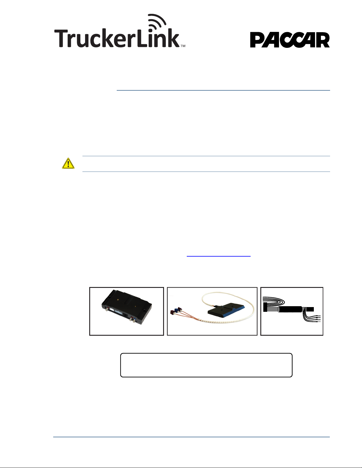
AMG1000BHx kit contents:
AMG1020x
Advanced Mobile Gateway
AMG1021B
Backpack Antenna
AMG1022H
Wiring Harness for
Heavy Duty Trucks
x=U if equipment is to be operated in the USAwhere:
x=C if equipment is to be operated in Canada
Advanced Mobile Gateway AMG1000
Heavy Duty Truck Kit
Installation Guide (AMG1000BHx)
1.0 Safety & Regulatory Information
Important safety and regulatory information on the AMG unit may be found on on page 13
of this installation guide.
CAUTION: Be sure to thoroughly review the safety and regulatory information before installing and
activating the AMG unit.
2.0 Kit Contents
There are two AMG aftermarket kits for heavy-duty trucks:
• AMG1000BHx kits include the “Backpack Antenna” and will be used in the majority
of cases, where both the base unit and the antenna are to be installed in the cab
interior.
• AMG1000AHx kits include the “External Antenna” and should be used when it is
necessary to install the antenna on the cab exterior or if specifically requested by
the “fleet” customer. Instructions for AMG1000AHx kit installation are not included
here, but are available online: support.truckerlink.com
This is the installation guide for the AMG1000BHx kit as shown in Figure 1.
AMG1000BHx HD Truck Kit Installation Guide 1
Release r05
Figure 1: AMG1000BHx Heavy Duty Truck Kit
Page 2

3.0 Recommended Tools
The following tools are recommended for the installation:
• Phillips and Square Drive screwdrivers – to unscrew the dashboard
• Pin Extractor – Deutsch Part Number: 0411-310-1605
• Punch – to assist in removing designated wires from J1939 if necessary
• Needle-nose pliers – to remove the wedge lock
• Carpenter knife – to separate wires C&D from covering over both wires (if needed)
• Zipties – to secure loose wiring and perhaps the AMG itself
IMPORTANT – PLEASE COMPLETE THE
FOLLOWING TASKS BEFORE
INSTALLATION
Turn the truck on and check for existing lamps, warning
lights, or anything out of the ordinary:
Investigate issues as needed before beginning the install – this thorough pre-install exam
helps troubleshoot issues should any arise after installation.
Pull the diagnostics fuse
This fuse will likely fail if not removed before installation begins. Refer to additional
documentation as needed to identify this fuse, as it will be in a different place for each make
and model of vehicle.
Activate the AMG:
Step 1: Obtain Required Information
The following information is required to activate an AMG unit:
• AMG Serial Number – see Figure 2 for location of this information
• Fleet Name – the name of the fleet the vehicle belongs to
• Truck Number – the number the fleet uses to identify the vehicle
• Dealer Code – the code for the dealership where the TruckerLink unit was
purchased from
• VIN – the Vehicle Identification Number for the vehicle in which the AMG unit will be
installed
• Odometer – the vehicle odometer reading from the dash
2 AMG1000BHx HD Truck Kit Installation Guide
Page 3

Figure 2: AMG Serial Number
P/N:
UNIT S/N:
1234567890
1234567890
AMG1020U
AMG1020U
(888) 558-6188 ext 1
Il est important que le numéro de série
de cet appareil soit associé au numéro
du camion qui recevra cet appareil.
It is important that the UNIT S/N is
associated with the Truck # that
will receive this unit.
Please call
to activate
Veuillez appeler
pour activer
AMG Serial Number
Bottom of AMG Unit
AMG Bar Code Label (Close Up)
P/N:
UNIT S/N:
1234567890
1234567890
AMG1020U
AMG1020U
MODEL: AMG1020U
FCC ID: OPP-AMG1020X
IC ID: 2943A-AMG1020
Unit mounted with backpack attached to base:
BEST
NOT
ADVISED
AVOID
ENTIRELY
The mounting location
should provide access
to the cable connections
on the AMG base unit.
Ideally, this side should be facing UP
with no metal objects between it and the
sky
The mounting
location should
allow the status
LEDs to be visible.
Step 2: Call 1-888-558-6188 ext. 1
Call this number once the information from Step 1 is obtained. A customer service agent will
then activate the unit. It will usually take a few minutes to complete.
Identify the best location for installation:
Before the wiring harness, AMG base unit, and antenna are installed, it is strongly
recommended that the vehicle cab is inspected for potential installation locations and an
installation plan is devised. Keep the following information in mind when locating a suitable
install location and plan:
1) The AMG base unit may not be installed any further than 16 feet away from the J1939
bus splice.
2) The backpack antenna (included in AMG1000BHx kits only) may be installed either on
the AMG unit itself or up to 3 feet away from the AMG base unit.
3) Antenna reception is critical for effective AMG operation, therefore the antenna must not
be obstructed by metal objects. Optimal antenna orientation is shown in Figures 3 & 4.
AMG1000BHx HD Truck Kit Installation Guide 3
Figure 3: Optimal Unit Orientation (antenna attached to base)
Page 4

Figure 4: Optimal Unit Orientation (antenna separated from base)
Backpack antenna and base unit mounted separately:
BEST
NOT
ADVISED
AVOID
ENTIRELY
AMG BASE UNIT
ORIENTATION
NOT CRITICAL
Ideally, this side of the backpack antenna
should be facing UP with no metal
objects between it and the sky
The mounting location
should provide access
to the cable connections
on the AMG base unit.
The mounting
location should
allow the status
LEDs to be
visible.
Note: Placement behind the dashboard has been most successful in field trials, and is therefore the
recommended location for AMGs with the backpack antenna.
A good install location will be one that:
• Is not visible to the driver
• Has clear line of sight to the sky for the backpack antenna, ideally as close to the
front of the cab as possible.
• Allows the backpack antenna to mount parallel to the ground – the ideal placement
is horizontal without any metal objects between it and the sky. Unscrew the antenna
if needed to place the antenna in an ideal place.
• Will allow the technician to be able to see all four LEDs on the unit.
• Allows easy access to the GPS, CDMA, and GSM connections on the unit
• Enables the AMG base unit to be secured via screws, such that the screws are not
visible to the driver.
Note: Record the Pre-Installation Information on the Installation Form located in AMG Kit.
PROCEED WITH INSTALLATION ONLY AFTER
THE ABOVE TASKS HAVE BEEN COMPLETED
4 AMG1000BHx HD Truck Kit Installation Guide
Page 5

4.0 Connecting the AMG
GSM
Cellular
Antenna
Connector
8 Pin
MOLEX
Connector
CDMA
Cellular
Antenna
Connector
GPS
Antenna
Connector
Unit
Status
LEDs
4.1 AMG Base Unit Connections
The AMG base unit connectors are shown in Figure 5.
Note: There are two cellular antenna connections, one is for GSM and the other is for CDMA. Be sure
to check connections made to the AMG unit thoroughly.
Figure 5: AMG Base Unit Connectors
4.2 Wiring Harness for Heavy Duty Trucks
The Wiring Harness is made from C1204 4-conductor shielded cable with an Molex 8-pin
mini fit connector and a Deutsch 4-pin in-line connector.
Figure 6: Wiring Harness for Heavy Duty Trucks
AMG1000BHx HD Truck Kit Installation Guide 5
Page 6
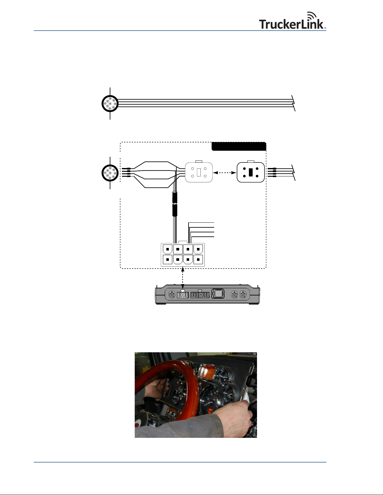
Wiring Harness Installation Overview
4
3
1
2
Deutsche 4-Pin
Receptacle
Deutsche 9-Pin
Connector
J1939 Bus
from Engine
Deutsche 9-Pin
Connector
J1939 Bus
from Engine
Pinout:
1 = VBATT
2 = CAN_H
3 = CAN_L
4 = GND
Deutsche 4-Pin
In-Line Connector
Remove pins from Deutsche
9-Pin Connector in vehicle
dashboard and attach to
Deutsche 4-Pin Receptacle
1
2
4
3
VBATT (Red)
GND (Black)
CAN_H (Yellow)
CAN_L (Green)
Vehicle Dashboard
Parking Brake (Orange)
Ignition Sensor (Brown)
1-Wire (Blue) [NOT USED]
Ground (Black)
Molex MiniFit Connector
Plugs into AMG base unit
12 43
56 87
5 = 1-Wire
6 = CAN_L
7 = CAN_H
8 = VBATT
Pinout:
1 = GND
2 = Ignition Sensor
3 = Parking Brake
4 = GND (Battery -)
WIRING HARNESS
Vehicle Dashboard
Attach pins from
wiring harness to
Deutsche 9-Pin
Connector
AMG base unit (Connector Side)
BEFORE AMG WIRING HARNESS IS INSTALLED
AFTER AMG WIRING HARNESS IS INSTALLED
Figure 7 shows the wiring harness installation overview. The following section provides the
detailed installation instructions.
4.3 Wiring Harness Installation Steps
1) Remove dashboard
Figure 7: Wiring Harness Installation Overview
Figure 8: Remove Dashboard
6 AMG1000BHx HD Truck Kit Installation Guide
Page 7

2) Locate the vehicle's Deutsch 9 pin connector (normally located on drivers left side under
C
A
V
A
)
CAN_
(Y
V
d
steering wheel and may be covered by a protective cap).
Figure 9: Deutsch 9-pin Connector Location
3) Remove the Deutsch 9-pin connector from the panel to access the wiring.
CAN_L (Green)
CAN_H (Yellow)
B
VBATT (Red)
D
C
B
J
E
F
A
G
GND (Black)
k
H
Pin Extractor
Deutsch PN: 0411-310-1605
Figure 10: Removed Deutsch 9 Pin Connector & Relevant Pins
4) Remove the pins designated A, B, C, and D from the Deutsch 9-pin connector on the
truck using a Deutsch pin extractor (Deutsch Part Number: 0411-310-1605).
Note: As each pin is removed, label each wire with its specific connection type (i.e. CAN_L,
CAN_H, VBATT, GND) for later reference, if the colors are not easily identified. Use Figure
1-10 above as a reference.
5) On the AMG wiring harness, locate the 4 wires with pre-installed pins as shown in Figure
11. Connect these wires to the A, B, C, and D slots of the vehicle's Deutsch 9-pin
connector as described in Table 1 and shown in Figure 11.
CAN_L (Green)
CAN_H (Yellow)
CAN_H
D
C
E
GND (Black)
B
A
BATT (Re
VBATT (Red)
J
G
H
Figure 11: Wiring Harness to CAN J1939 Bus Wiring Configuration
AMG1000BHx HD Truck Kit Installation Guide 7
F
Page 8

Table 1: Wiring Harness to CAN J1939 Bus Wiring Configuration
Wedge Lock
Pin 3: CAN_L (Green)
Pin 2: CAN_H (Yellow)
Pin 1: VBATT (Red)
Pin 4: GND (Black)
Wire Color
(from Harness)
Black GND (Battery -) Battery Return A
Red VBATT (Battery +) Positive Battery Supply (12VDC) B
Yellow CAN_H CAN bus line, dominant high C
Green CAN_L CAN bus line, dominant low D
6) Locate the Deutsch 4-pin receptacle and remove the wedge lock using needlenose
pliers.
Signal Description Deutsch 9-pin
Figure 12: Deutsch 4-pin Receptacle
7) Locate the four pins that were removed from the vehicle's Deutsch 9-pin connector in
step 4 and insert them into the narrow side of the Deutsch 4-pin receptacle shown in
Figure 13. Ensure that pins are fully seated in the receptacle - a 'click' will be heard
when done properly. Use the wire labels as reference, if applied in Step 4.
Figure 13: Insert Wires into Deutsch 4-pin Receptacle
8 AMG1000BHx HD Truck Kit Installation Guide
Page 9

8) Once all the pins are in, insert the Green wedge lock into the center of the Deutsch 4-pin
receptacle using needlenose pliers until it locks in place. Ensure that the pins have been
inserted deep enough into the 4 pin receptacle so that no part of the pins are exposed
on the back and that the pins protrude above the wedge lock as shown in Figure 14.
Figure 14: Deutsch 4-pin Receptacle with Wedge Lock
9) Connect the Deutsch 4-pin plug housing on the wiring harness to the receptacle
housing.
Figure 15: Deutsch 4-pin Receptacle and Housing
Note: If the four wires that extend from the Molex 8-pin connector wires are not to be connected at
this time, make sure they are cable tied and out of the way.
10)Connect the Ignition Sensor (Brown), Parking Brake (Orange) and Ground
(Black) wires from the Molex 8-pin connector (see Figure 7) accordingly.
CAUTION: The Ignition Sensor and Parking Brake wires on the vehicle may be live. Take appropriate
measures such as removing the applicable fuse(s) or disconnecting the vehicle battery before
connecting these sensors to the AMG.
Note: The 1-Wire (Blue) wire is not used and should be capped off to prevent making electrical
contact.
11)Replace the diagnostics fuse that was removed earlier. Check all wiring connections to
ensure that they have been made correctly.
AMG1000BHx HD Truck Kit Installation Guide 9
Page 10

5.0 Mounting the Unit
Once the AMG is connected to the Molex 8-pin connector as well as the Deutsch 4-pin
connector, the AMG base unit may be secured to the vehicle. An AMG is properly secured
when:
• It cannot be easily moved or jostled around
• The backpack antenna remains horizontal, with a clear line-of-sight to the sky. The
backpack antenna needs to be secured also if it has been unscrewed from the AMG.
• The 4 lights on the AMG are visible so that proper operation of the AMG may be
confirmed.
• No wires are loose or unsecured.
Securing the unit using Screws (preferred)
The unit may be secured to the vehicle using two #8 Pan Head Screws with a maximum
head diameter of 0.325". The recommended maximum torque is 6.0 in-lbs. If holes are to
be pre-drilled, space them 6 inches apart as shown in Figure 16.
Head diameter 0.325" max.
Maximum torque 6.0 in-lbs
#8 Pan Head Screw
Area of the vehicle to
anchor AMG unit
4.03”
3.65”
#8 Pan Head Screw
Head diameter 0.325" max.
Maximum torque 6.0 in-lbs
1.80”
0.175”
1.85”
6.00”
6.80”
Figure 16: Securing the AMG base unit using Screws
10 AMG1000BHx HD Truck Kit Installation Guide
Page 11

Securing the unit using Zip Ties
The unit may be secured to the vehicle using two zip ties as shown in Figure 17. Note that
the zip ties should be positioned inside the zip tie fences on the AMG base unit enclosure.
Zip Tie fences prevent the
zip ties from slipping off side
Area of the vehicle to
anchor AMG unit
Figure 17: Securing the AMG base unit using Zip Ties
6.0 Mounting the Antenna
The backpack antenna may be mounted directly on the AMG base unit once the base unit is
secured to the vehicle. Alternatively, if desired the backpack antenna may be mounted up to
3 feet away from the AMG base unit using two #6 or M3.5 Pan Head Screws with a
maximum head diameter of 0.275". The recommended maximum torque is 5.0 in-lbs. If
holes are to be pre-drilled, space them 3 inches apart as shown in Figure 18.
Position Zip Tie on inner
side of fence
AMG1000BHx HD Truck Kit Installation Guide 11
Page 12

7.0 Confirm AMG Operation
#6 or M3.5 Pan Head Screw
Head diameter 0.275" max.
Maximum torque 5.0 in-lbs
3.29”
4.47”
1.63”
1.78”
4.78”
6.55”
0.150”
x 2
1.12”
The unit is working properly when all four lights are green and blinking. Power up the truck
to confirm this is the case. PWR, CELL, and DATA lights should begin to maintain a green and
blinking status within 60 seconds – the GPS LED may need a few minutes longer. Once all
four lights are green and blinking, re-install the dashboard.
IF ALL FOUR LIGHTS ARE NOT GREEN AND BLINKING...
8.0 Return the AMG Installation Form
• If the “DATA” light is not green and blinking – confirm the connection to the J1939
databus is completed as described in this guide.
• If “GPS” or “CELL” light is not green and blinking (i.e., unblinking amber), and the
vehicle is in a garage, drive the vehicle outside with a clear line-of-sight to the sky.
If the vehicle is already outside, check the position of the backpack antenna, making
sure it is parallel to the ground and not obstructed by any metal objects. If these
lights are still not green and blinking, call 888-558-6188 ext 1 for installation
assistance.
• If the “PWR” light is not green and blinking (i.e., all lights are off or PWR is
unblinking red), please recheck the power cables and connectors. If the problem
persists please call 1-888-558-6188 ext. 1 for installation assistance.
Note: Record the Post-Installation Information on the Installation Form located in AMG Kit.
Fax the completed AMG Installation form to (206) 316-2302.
Figure 18: Backpack Antenna Mounting Holes
12 AMG1000BHx HD Truck Kit Installation Guide
Page 13

9.0 Safety & Regulatory Information
Document Conventions
This document uses the following special formats to emphasize key information. Be aware of
all warnings and cautions before you begin to use AMG1000BHx.
WARNING! Whenever you see this icon and heading, the associated text addresses or discusses a
critical safety or regulatory issue.
CAUTION: Whenever you see this icon and heading, the associated text discusses an issue which
could result in damage or abuse of the equipment. Carefully read and follow these instructions.
Safety Precautions
Read and follow the following safety instructions before installing or operating an
AMG1000BHx kit.
WARNING! Before installing or operating this equipment, read all safety, installation and operating
sections. Follow all instructions - failure to do so may result in damage to the unit or severe personal
injury. Retain this manual for future reference.
Avant d'installer ou d'opérer cet équipement, lisez, toutes les sections de sécurités, d'installations et
d'opérations. Gardez ce manuel comme source de référence. Suivez toutes instructions - si non, vous
risquez d'endommager la machine ou de vous blesser sérieusement.
WARNING! Servicing should not be attempted by the user. There are no user serviceable parts
inside. Refer all servicing to factory qualified personnel.
N'essayez, pas de réparer cet équipement vous même. Référez toutes revisions nécessaire au personnel
qualifié de la manufacture.
WARNING! Cleaning - Do not use liquid or aerosol cleaners. Use a damp cloth for cleaning.
Le nettoyage - n'utilisez pas de nettoyeurs aérosols ou liquides. Utilisez un tissu humide pour nettoyer.
WARNING! Electrostatic discharge (ESD) can damage equipment and impair electrical circuitry. ESD
damage occurs when electronic components are improperly handled and can result in complete or
intermittent failures. Always follow ESD-prevention procedures when you are working on an AMG base
unit or antenna. Ensure that the unit is electrically connected to an earth ground and wear a properly
grounded ESD-preventive wrist strap. If no wrist strap is available, ground yourself by touching the
metal part of the unit.
WARNING! The installation of your AMG device must comply with vehicle wiring standards and best
practices.
WARNING! Fuse-handling equipment must be used to remove or install fuses and shunts when the
terminals are energized. The tool must be insulated for the circuit voltage.
WARNING! Disconnect all power before installing or removing a chassis. Never assume that power
is disconnected from a circuit. Always check.
Note: Keep the chassis area clear and dust-free during and after installation.
AMG1000BHx HD Truck Kit Installation Guide 13
Page 14

Note: Do not perform any action that creates a potential hazard to people or makes the equipment
unsafe.
CAUTION: To comply with Industry Canada RF exposure requirements, a minimum separation
distance of 8 inches (20 centimeters) is required between this antenna and all persons.
Pour conformer aux conditions d’exposition RF d’Industry Canada, une distance minimum de séparation
de 20 centimètres est exigée entre l’antenne et toutes personnes.
Regulatory Notices
Federal Communications Commission (FCC) Compliance
This device complies with Part 15 of the FCC Rules. Operation is subject to the following two
conditions:
• This device may not cause harmful interference, and
• This device must accept any interference received, including interference that may
cause undesired operation.
This equipment complies with FCC radiation exposure limits set forth for an
occupational/controlled environment
The antenna(s) used for this transmitter must be installed to provide a separation distance
of at least 8” (20cm) from all persons and must not be co-located or operating in
conjunction with any other antenna or transmitter.
This transmitter is approved for use with the antennas supplied with this equipment.
Maximum Antenna gains (including cable loss) are:
AMG1021B Backpack Antenna: +1.6dBi (GSM 850) and +2.9dBi (PCS1900).
AMG1021A External Antenna: -1.0dBi (GSM 850) and -1.7dBi (PCS1900).
Use of different antennas is not permitted. Failure to comply will invalidate FCC rule
compliance.
WARNING! Changes or modifications not expressly approved by Vecima Networks Inc. could void
the user’s authority to operate the equipment.
Industry Canada Compliance
This device complies with Industry Canada license-exempt RSS standard(s). Operation is
subject to the following two conditions:
• This device may not cause interference, and
• This device must accept any interference, including interference that may cause
undesired operation of the device.
This device has been designed to comply with safety requirements for exposure to radio
waves (SAR) in accordance with RSS-102. This device should be installed and operated with
minimum distance 20cm between the equipment and your body.
Le présent appareil est conforme aux CNR d'Industrie Canada applicables aux appareils
radio exempts de licence. L'exploitation est autorisée aux deux conditions suivantes:
• L'appareil ne doit pas produire de brouillage, et
• L'utilisateur de l'appareil doit accepter tout brouillage radioélectrique subi, même si
le brouillage est susceptible d'en compromettre le fonctionnement.
14 AMG1000BHx HD Truck Kit Installation Guide
Page 15

Cet artifice a été conçu pour se plier à la sécurité les exigences pour l'exposition aux ondes
radioélectriques (SAR) dans conformité avec RSS-102. Cet artifice devrait être installé et fait
marcher avec la distance minimale 20 centimètres entre l'équipement et votre corps.
Under Industry Canada regulations, this radio transmitter may only operate using an
antenna of a type and maximum (or lesser) gain approved for the transmitter by Industry
Canada. To reduce potential radio interference to other users, the antenna type and its gain
should be so chosen that the equivalent isotropically radiated power (e.i.r.p.) is not more
than that necessary for successful communication.
Conformément à la réglementation d'Industrie Canada, le présent émetteur radio peut
fonctionner avec une antenne d'un type et d'un gain maximal (ou inférieur) approuvé pour
l'émetteur par Industrie Canada. Dans le but de réduire les risques de brouillage
radioélectrique à l'intention des autres utilisateurs, il faut choisir le type d'antenne et son
gain de sorte que la puissance isotrope rayonnée équivalente (p.i.r.e.) ne dépasse pas
l'intensité nécessaire à l'établissement d'une communication satisfaisante.
This radio transmitter (IC: 2943A-AMG1020) has been approved by Industry Canada to
operate with the antenna types listed below with the maximum permissible gain and
required antenna impedance for each antenna type indicated. Antenna types not included in
this list, having a gain greater than the maximum gain indicated for that type, are strictly
prohibited for use with this device.
Le présent émetteur radio (IC: 2943A-AMG1020) a été approuvé par Industrie Canada pour
fonctionner avec les types d'antenne énumérés ci-dessous et ayant un gain admissible
maximal et l'impédance requise pour chaque type d'antenne. Les types d'antenne non inclus
dans cette liste, ou dont le gain est supérieur au gain maximal indiqué, sont strictement
interdits pour l'exploitation de l'émetteur.
AMG1021B Backpack Antenna - Impedance: 50 Ohm Nom.; Maximum Gain, including cable
loss: -1.0dBi (GSM 850) and -1.7dBi (PCS1900).
AMG1021A External Antenna – Impedance: 50 Ohm Nom.; Maximum Gain, including cable
loss : +1.6dBi (GSM 850) and +2.9dBi (PCS1900).
AMG1000BHx HD Truck Kit Installation Guide 15
Page 16

INSTALLATION STANDARD: The buyer and/or installer agrees that it is fully experienced and
properly qualified to perform the installation work provided for herein, and that it is properly licensed,
equipped, organized and financed to perform such work. The buyer and/or installer will perform all
installation work in accordance with its own methods on a best efforts basis subject to compliance with
the instructions set out herein and in accordance with generally accepted professional standards. Failure
to do so will render the Vecima Network’s Inc. warranty null and void to the maximum extent allowed
under applicable law.
LIMITED LIABILITY: Vecima Networks Inc. shall not be liable to the buyer, installer or any third party
for any indirect or consequential loss or damages including, without limitation, loss of business or profits
whether arising under any indemnity or from negligence, breach of contract or otherwise. Vecima
Networks Inc. shall also not be liable if the installation and/or use of the product voids any other
warranty which the buyer, installer, and/or any third party benefits from, including but not limited to
vehicle manufacturer warranties. The buyer, installer, or any third party’s 's total recovery from Vecima
Networks Inc. shall not exceed the price the buyer has paid for the specific unit of product giving rise to
the claim.
USE IN CRITICAL MEDICAL SYSTEMS PROHIBITED: PRODUCTS SOLD BY VECIMA ARE
NOT DESIGNED, INTENDED OR AUTHORIZED FOR USE IN LIFE SUPPORT, LIFE
SUSTAINING, NUCLEAR, OR OTHER APPLICATIONS IN WHICH THE FAILURE OF SUCH
PRODUCTS COULD REASONABLY BE EXPECTED TO RESULT IN PERSONAL INJURY, LOSS
OF LIFE OR CATASTROPHIC PROPERTY DAMAGE. IF BUYER USES OR SELLS THE
PRODUCTS FOR USE IN ANY SUCH APPLICATIONS: (1) BUYER ACKNOWLEDGES THAT
SUCH USE OR SALE IS AT BUYER’S SOLE RISK; (2) BUYER AGREES THAT VECIMA IS NOT
LIABLE, IN WHOLE OR IN PART, FOR ANY CLAIM OR DAMAGE ARISING FROM SUCH USE;
AND (3) BUYER AGREES TO INDEMNIFY, DEFEND AND HOLD VECIMA HARMLESS FROM
AND AGAINST ANY AND ALL CLAIMS, DAMAGES, LOSSES, COSTS, EXPENSES AND
LIABILITIES ARISING OUT OF OR IN CONNECTION WITH SUCH USE OR SALE. Furthermore,
this device (AMG1020) may cause interference to other radio devices operating in the frequency band
155.1525MHz to 155.1825MHz; this frequency band is typically used by 2 way radio devices licensed
for use in accordance with United States Code of Federal Regulations, Title 47, part 90, section 90.20 Public Safety Pool.
LAW AND VENUE: The validity and interpretation of these terms shall be governed by the laws of the
Province of British Columbia and Canada and any such dispute shall be submitted exclusively to the
British Columbia courts. The parties agree that any conflicts of laws provisions, where applicable, are
hereby excluded by this express agreement to attorn to the specified law and venue.
PERMISSION TO REPRODUCE: Except as otherwise specifically noted, the information in this
publication may be reproduced, in part or in whole and by any means, without charge or further
permission from Vecima Networks Inc., provided that due diligence is exercised in ensuring the accuracy
of the information reproduced; that Vecima Networks Inc. is identified as the source; and that the
reproduction is not represented as an official version of the information reproduced.
WARRANTY: Vecima Networks Inc. provides this guide without warranty of any kind, either implied or
expressed, including, but not limited to, the implied warranties of merchantability and fitness for a
particular purpose. Any representation(s) in this document concerning performance of Vecima Networks
product(s) are for informational purposes only and are not warranties of future performance, either
express or implied. Vecima Networks Inc. reserves the right to revise this publication and to make
changes in content from time to time without obligation on the part of Vecima Networks Inc. to provide
notification of such revision or change.
Vecima Networks Inc.
150 Cardinal Place
Saskatoon, SK, Canada S7L 6H8
Published in Canada.
Specifications subject to change without notice.
16 AMG1000BHx HD Truck Kit Installation Guide
 Loading...