

Page 1

Operating Manual for
STADTROLLER
BERLIN
SR59
VEB INDUSTRIEWERKE LUDWIGSFELDE
Edition 1960
Page 2

The Stadtroller „SR 59-Berlin“ is a Product of VEB Industriewerke Ludwigsfelde.
Scooterstation offers full parts support for the SR59 Berlin scooter within the US. If you need parts
you can contact us at: (503)-231-2768 or e-mail us at [email protected]
This operating manual was was written by a collective of Authors of the VEB Industriewerke
Ludwigsfelde.
All rights reserved – Technical books press Leipzig GDR – Type setting & print: Technical books
print Naumburg (Saale) GDR.
Editorship conclusion: 11/1/1959
KG 12/3/60
Page 3

A lot of unnecessary frustration
will be avoided if you don´t put this operating manual aside carelessly, but instead briefly familiarize
yourself with the directions and suggestions this manual provides. All sections of this manual have
been compiled by skilled personell and serve the purpose of imparting knowledge about this vehicle
to you without which the operation of a modern motorvehicle would just be impossible. We want to
give you the maintenance and care advice necessary for you to be able to enjoy your vehicle,
instead of having to spend your valuable free time at an authorized dealers shop, that you should
better use for your own recreation.
It´s a simple fact that any new motorvehicle should be treated with a lot of care and attention. This
is why you will save lots of money, frustration and potential anger if you apply the knowledge
gained from this operating manual. Not only should you consider the given advice for a single ride,
but for the entire time in which you drive your motorscooter.
Please consider that the observance of our advice essentially contributes to the preservation of
your property and thus to the peoples property.
If you don´t find the information on the following pages sufficient or if you need additional advice,
you can always trustfully contact one of our authorized dealers. They will always help and advise
you, because our authorized dealers ought to avoid repairs before they happen by making qualified
suggestions and giving helpful advice.
VEB Industriewerke Ludwigsfelde
This manual was translated into english by Stephan Henkel and is property of Scooterstation Inc.,
OR. U.S.A. Copying or reproduction of this manual is prohibited without the written consent of
Scooterstation Inc.,USA. © 2002 Scooterstation. All rights reserved.
LEGAL DISCLAIMER:
This manual is to serve the purpose of reference only. Scooterstation is not responsible for any
malfunction or damage of your scooter resulting in the use of this manual. Scooterstation is not
responsible for any possible personal injuries or death that may result in the use of this manual.
Page 4

Table of contents
1. Technical data ..................................................................................................... 11
1.01 Engine......................................................................................................... 11
1.02 Transmission and drivetrain........................................................................ 12
1.03 Brakes......................................................................................................... 13
1.04 Wheels........................................................................................................ 14
1.05 Suspension.................................................................................................. 14
1.06 Steering....................................................................................................... 15
1.07 Electrical system......................................................................................... 15
1.08 Frame.......................................................................................................... 15
1.09 Body............................................................................................................ 16
1.10 Equipment
1.11 Dimensions & weight.................................................................................... 16
1.12 amounts of fillings........................................................................................ 17
2. Description.............................................................................................................. 18
2.1 Engine........................................................................................................... 18
2.11 Mode of operation.............................................................................. 18
2.12 Crankshaft......................................................................................... 22
2.13 Crankcase......................................................................................... 25
2.14 Cylinder and Cylinder head................................................................ 27
2.15 Piston and piston rod......................................................................... 29
2.16 Fan.................................................................................................... 30
2.17 Electrical System.............................................................................. 32
............................................................................................ 16
2.161 Verifying the fan-drivebelt..................................................... 30
2.162 Changing the drivebelt.......................................................... 31
2.171 alternator............................................................................. 32
2171.1 Verifying the Electrical system............................... 34
2.171.2 Electrical tuneup (every 6000 miles)...................... 35
2.127 Battery.................................................................................. 37
2.172.1 Maintenance.......................................................... 38
2.172.2 Insufficient charging of Battery............................... 39
2.173 Lights and signals................................................................. 39
2.173.1 Failure of signal horn
2.174 Regulator.............................................................................. 41
2.175 Ignition.................................................................................. 41
Page 5

2.18 Carburetor and airfilter...................................................................... 43
2.181 Maintenance of carburetor.................................................... 45
2.182 Cleansing the airfilter............................................................ 50
2.2 Power Train................................................................................................. 52
2.21 Primary Transmission and clutch...................................................... 52
2.211 Adjusting the clutch.............................................................. 53
2.22 Gearbox............................................................................................ 55
2.23 Rear powertransmission.................................................................... 56
2.231 Chain maintenance.............................................................. 57
2.3 Chassis....................................................................................................... 60
2.31 Frame............................................................................................... 60
2.32 Front wheel balance beam fork......................................................... 61
2.321 Disassembling the balance beam fork.................................. 62
2.322 Adjusting the steering column bearings................................ 63
2.33 Rear wheel suspension..................................................................... 64
2.331 Disassembling the rear wheel suspension............................ 65
2.34 Brakes.............................................................................................. 66
2.341 Brake maintenance............................................................. 67
2.35 Axles and wheels............................................................................. 69
2.351 Flat tire............................................................................... 70
2.36 Tank................................................................................................ 74
2.361 Cleansing the fuelfilter
.................................................... 75
2.37 Driver- and buddyseat...................................................................... 76
2.38 Instrument panel and theft protection............................................... 77
2.39 Tools................................................................................................ 78
3. Operating instructions............................................................................................ 80
3.1 Location and purpose of control levers and knobs....................................... 80
3.101 Air lever (Choke).............................................................................. 81
3.102 Throttle............................................................................................. 81
3.103 Ignition and lightswitch...................................................................... 82
3.104 Dipswitch.......................................................................................... 84
3.105 Clutch............................................................................................... 85
3.106 Kickstarter........................................................................................ 86
3.107 Foot gear switch............................................................................... 86
3.108 Rear brake foot lever........................................................................ 88
3.109 Front brake lever.............................................................................. 89
3.110 Sidestand......................................................................................... 89
3.111 Tip up hook...................................................................................... 90
3.2 Correct operation........................................................................................ 90
3.21 Before your first ride......................................................................... 90
3.22 Running in........................................................................................ 92
3.23 Starting up........................................................................................ 93
Page 6

3.24 Start and shifting gears................................................................ 94
3.25 Shifting down gears on a slope......................................................... 94
3.26 Slowing down / using your brakes..................................................... 96
3.27 Stopping........................................................................................... 96
3.28 Mothballing the bike for storage........................................................ 96
4. Checkup- and maintenance work........................................................................... 98
4.1 General Information.................................................................................... 98
4.2 What do do ?.............................................................................................. 98
4.21 Daily................................................................................................. 98
4.211 Before leaving the driveway................................................ 98
4.212 During stays in transit.......................................................... 99
4.213 After returning..................................................................... 99
4.22 Lubricating the engine...................................................................... 99
4.23 Lubricating the chassis..................................................................... 100
4.24 maintenance of sparkplug................................................................ 100
4.241 What does the sparkplug´s face tell us ?............................. 102
4.25 Cleansing the exhaust pipe.............................................................. 103
4.3 Troubleshooting.......................................................................................... 104
4.31 Engine won´t start............................................................................. 104
4.32 Red controllamp doesn´t go out after start or lights up during ride..... 107
4.33 Fan controllamp doesn´t go out after start or lights up during ride..... 107
4.34 Engine doesn´t run smooth................................................................ 107
4.35 Engine stalls abruptly......................................................................... 108
4.36 Excessive fuel consumption............................................................... 108
4.37 Headlight doesn´t work...................................................................... 109
4.38 Adjusting the Headlight..................................................................... 110
5. Repair instructions....................................................................................... 112
5.1 Engine, removal and installation of.............................................................. 112
5.2 Cylinderhead, removal of
....................................................................... 113
5.3 Cylinder, removal of
5.4 Piston, removal of....................................................................................... 113
5.5 Pistonring, inspection of and exchange....................................................... 114
.............................................................................. 113
Page 7

5.6 Piston and cylinder, installation of............................................................... 115
5.7 Ignition timing, adjustment of...................................................................... 117
5.8 Wheelbearing, exchange of......................................................................... 118
6. Parts support and technical service.............................................................. 120
Page 8
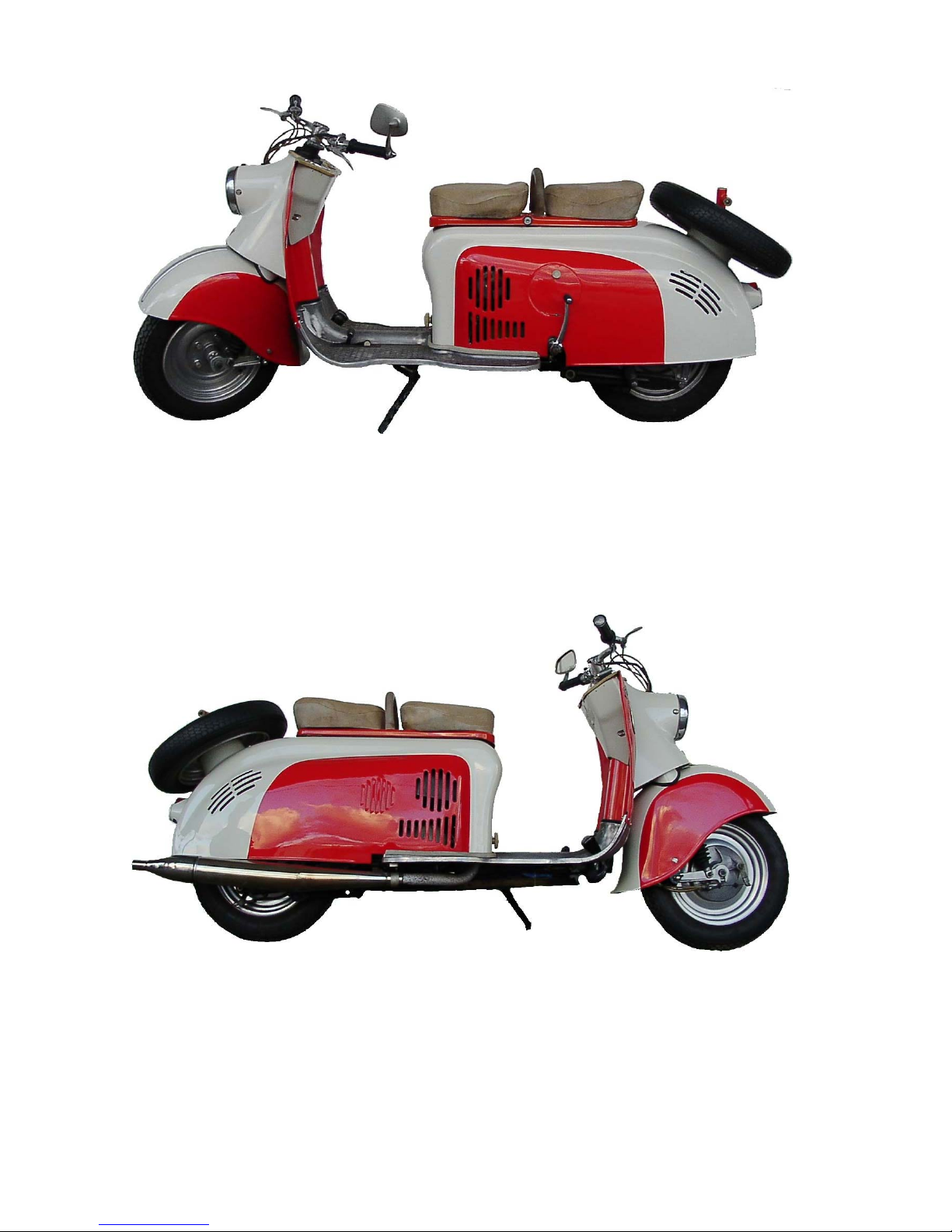
Illustration 1: Berlin SR59 as viewed from the left
Illustration 2: Berlin SR59 as viewed from the right
Page 9

1 Technical data
1.01 Engine
Mode of operation Two-stroke
Process Loop scavenging
Piston stroke 58mm
Cylinder bore 56mm
No. Of cylinders and
Orientation 1 cylinder, standing, leaning 15º forward
Piston displacement 143ccm
Compression ratio 7.75:1:8.1
Room for compression 20,4ccm
Continous output at 4000rpm 6.5hp
Maximum output at 5100rpm 7.5hp
Max. torque at 3500rpm 1.15kgm
Coolant Forced air (axial load supercharger)
Lubrication 4%
Carburetor
Design Round slidegate valve carburetor
Type 24 KN 1-1
Passage 24mm
Main jet 90
Needle jet 67
Idle jet 40
Needle setting 3
slidegate valve-cut out4mm
Idle air screw 2,5 to 3 revolutions, open
Weight of float 10,6grams
Airfilter Baffle wet air filter with intake silencer
Ignition Battery Ignition
Spark plug Isolator M 14-240
Length of thread 10mm
Elektrodenabstand 0,6mm
Unterbrecherkontaktabstand 0,4mm
Vorzündung 4mm of OT (28% crankangle), fixed setting
Piston
Material Si 20
Piston rings 2 Compression rings
Oversizes for cylinder-diameter 56.25; 56.50; 56.75; 57.00mm
Crankshaft bearings
Amount 3
Type Ball bearings
Connecting rod bearings Doublerowed roller bearings, cageless, with friction disc
Dimension of rolls 5x5 in compliance to DIN 5402
Page 10

1.02 Transmission and power transmission
Clutch Multiple disc clutch in oilbath, adjustable at motor
and handlebar
Coating Frictionlambals „Original Cosid“
Number of compression
springs 6
Transmission Docked to engine, hand controlled
Number of gears 4
Idle motion display electronic pilot lamp on lefthandside of controlpanel
Gearshift by footswitch and circuit breaker
Gears
1. gear 3.05 :1
2. gear 1.805 :1
3. gear 1.285 :1
4. gear 1 :1
Ratio
Engine/Transmission 2.75 :1
Transm./Rear wheel 2.19 :1
Gear ratio
1. Gear 18.4 :1
2. Gear 10.8 :1
3. Gear 7.73 :1
4. Gear 6.02 :1
Kickstart ratio 3.76 :1
Power transmission
Engine/Transmission Sleeve chain 3/8“ x 7.7 x 5Dmr.
44 links
Transm./Rear wheel Chain ½“ x ¼ “
x 8.51 Dmr. 94 rollers
1.03 Brakes
Foot brake Drum brake
Effective to Rear wheel
Operates through Bowden cable
Handbrake Drum brake
Effective to Front wheel
Operates through Bowden cable, adjustable at
hub and handle bar
Diameter of brake drums
rear/front 150mm
Brake lining
width 24mm
Material „Original Cosid“, glued on
Page 11

1.04 Wheels
Type Full disc wheels, light alloy
Axles
Front wheel Normal axle
Rear wheel Knockout spindle
Rims Drop base rims 2.50 C x 12
Tires
Dimensions 3.50-12
Type Block profile
Air Pressure
Front 1.2atü (17.64psi) single driver
Rear 1.5atü (22.05psi) single driver
Front 1.4atü (20.58psi) with buddy
Rear 2.0atü (29.40psi) with buddy
1.05 Suspension
Front wheel suspension Balance beam fork, Pressure spring with friction damping
Effect Proportional
Displacement 110mm
Rear wheel suspension Trapezoid swing, torsion spring (patented), hydraulically
absorbed
Effect Proportional
Displacement 70mm
1.06 Steering
Lenkkopfwinkel 25º
Vorderradnachlauf 75mm
Lenkanschlag At Steering shaft
Lenkwinkel 90º
1.07 Electrical System
alternator Voltage regulating
Type GMR 6/60
Manufacturer FEK (Fahrzeugelektrik Karl-Marx-Stadt)
Performance 60W
Propulsion Anchored directly on crankshaft tap
Controller RSC 60/6 on Blowercasing
Charging control lamp on the lefthandside of the controlpanel
Fuse 15A
Ignition coil TJ 6/1 at crankshaft tap
Battery
Voltage 6V
Capacity 8Ah
Negative pole to ground
Headlight 130mm face
Main light 35/35W Bilux
Page 12

1.08 Frame
Type Central frame
Seams Electrical and autogenic welding seams
Stand Sidestand on left side of floorboard
1.09 Body
Front Fender, Legshield, headlight with casing,
instrument panel
Floor and Rear Floorboard made from GA1-alloy, Rear hood
with removable toolbox and tippable seats, that
can be locked
Number of seats 2
1.10 Equipment
Speedometer Installed on instrumentpanel with nightlight
Propulsion through the front wheel
Tools Under the seats in the rear hood
1.11 Measurements and weights
Maximum length 2080mm
Maximum width 650mm
Maximum height 950mm
Wheelbase 1430mm
Ground clearance 110mm (loaded)
Wading capability 240mm
Turning circle 4.0 Meters
Weight 140Kg (309lbs.)
Dry curb weight 131Kg (289lbs.)
Maximum weight 300Kg (662lbs.)
Pressure on front axle
unloaded 51Kg (112lbs.)
loaded 100Kg (221lbs)
Pressure on rear axle
unloaded 84Kg (185lbs.)
loaded 200Kg (442lbs.)
Avg. Fuel consumption 2.8liters/100Km (85mpg)
Fuel consumption at speeds
of 40Km/h (25mph) 2.1l/100Km (112mpg)
of 50Km/h (31mph) 2.4l/100Km (99mpg)
of 60Km/h (37.5mph) 2.9l/100Km (82mpg)
Top speed 82Km/h (51mph)
Continous top speed 75Km/h (47mph)
climbing ability (single driver) 1
st
gear 33% (30º) at 15Km/h (9.5mph)
nd
2
gear 18% (16º) at 30Km/h (19mph)
rd
3
gear 12% (11º) at 50Km/h (31mph)
th
4
gear 5% (4.5º) at 60Km/h (37.5mph)
Page 13

1.12 Filling amounts
Fuel tank 12 liters ( 3.2 US gallons)
Reserve in fuel tank 1.5 liters (1.6 US liquid quarts
Transmission oil 0.4 – 0.45 liters (0.84-0.95 US liquid pints)
Radius with one tank filling appx. 350Km (219miles)
)
Page 14
2 Description
2.1 Engine
2.11 Mode of operation
The aircooled supercharged single cylinder two-stroke engine of the SR59 Cityscooter operates as
a loop-scavenging-triple-port-Engine. This engine is an advanced version of the reliable and
successful 125cc two-stroke motor of the MZ-125-2 Motorbike. The following section describes the
mode of operation of the RM150 engine:
As the piston moves upward (from bottom dead center (BDC) to top dead center(TDC)), a vacuum
is created beneath the piston in the enclosed volume of the crankcase. The piston uncovers a little
air inlet just before reaching the top dead center. This little air inlet is the end of the intake port,
through which fresh air enters the crank case due to the vacuum created before. Because this very
same air had to pass through the carburetor prior to entering the crank case, it is mixed with just the
right amount of fuel and oil (the oil being necessary for the lubrication of the engine) When the
piston is on a downward move after passing TDC it relocks the intake port and thus compresses the
air/fuel mix. By now, the oil has dropped out of the mix and attached itself to bearings and other
parts within the engine. Just before reaching BDC two openings called transfer ports are uncovered
in the cylind
The scavenging phase has begun. Meaning that the unburned mixture gasses are flowing out of the
transfers and merging together to form a loop. The gasses travel up the backside of the cylinder
and loops around in the cylinder head to scavenge out the burnt mixture gasses from the previous
power stroke. It is critical that the burnt gasses are scavenged from the combustion chamber, to
make room for as much unburned gasses as possible. Now the loop of unburned mixture gasses
have traveled into the exhaust pipe's header section. Most of the gasses aren't lost because a
compression pressure wave has reflected from the baffle cone of the exhaust pipe, to pack the
unburned gasses back into the cylinder before the piston closes off the exhaust port. Now the
crankshaft has rotated past bottom dead center (BDC 180 degrees) and the piston is on the
upstroke. The compression wave reflected from the exhaust pipe is packing the unburned gasses
er.
back in through the exhaust port as the piston closes off the port to start the compression phase.
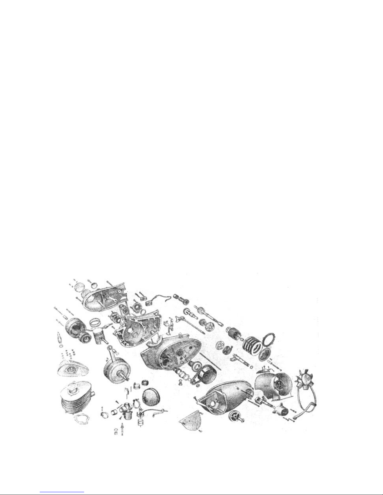
Image 3. Explosion drawing of engine
Page 15

Image 4. Power curve chart
Page 16
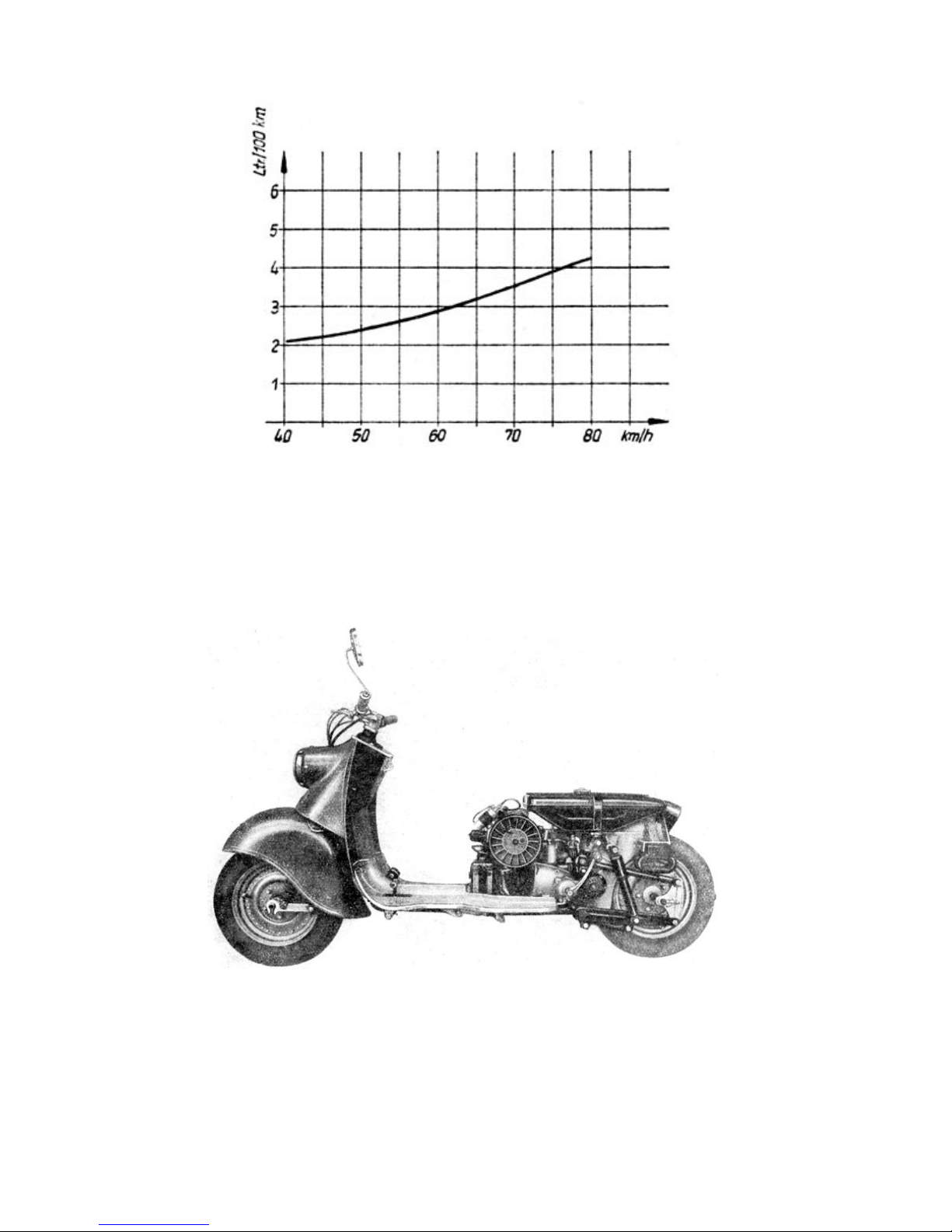
Image 5. Gas consumption curve
In the crankcase the pressure is below atmospheric producing a vacuum and a fresh charge of
unburned mixture gasses is flowing through the intake into the crankcase. The unburned mixture
gasses are compressed and just before the piston reaches TDC, the ignition system discharges a
spark causing the gasses to ignite and start the process all over again.
Image 6. Motor viewed from left side
Page 17
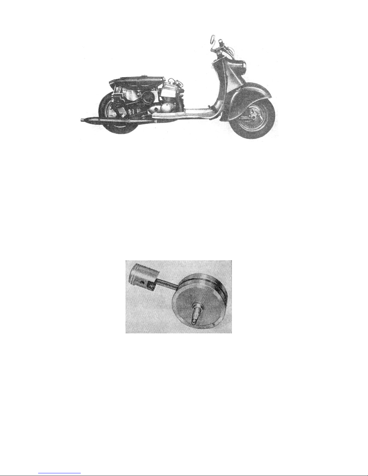
Image 7. Motor viewed from right side
2.12 Crankshaft
The crank is made from several metal parts, that were manufactured hydraullically under several
tons of pressure. These parts consist of the two strokediscs, the two crank pivots and the
strokepivot on which the connecting rod is installed on a doublerowed rollerbearing. A polished
seperator disc seperates the two rows of rollers and thus keeps an ideal tracking and also insures
sufficient lubrication even at high revolutions. At the top end of the connecting rod there is a
bronze bushing into which the piston bolt is installed.
The crank is installed into the crankcase by one ball bearing on the right and two ballbearings on
the left. The necessary pressuretightness of the crankendings at the bearings is achieved by spring
pressured crank seals on each side.
Image 8. Crank with connecting rod and
piston
2.13 Crankcase
The enginecase is sliced vertically through the middle. The front section contains the crankcase
and the rear section the transmissioncase.The crankcase picks up the crank and carries the
cylinder. The two halfes of the engine case are held together by screws . The seperation surfaces
of both halfes of the engine case should have minor amounts of a fluid sealer applied to them prior
to closing the enginecase. Two lightmetal cast lids close the exposed areas around the sides of the
enginecase.
Page 18
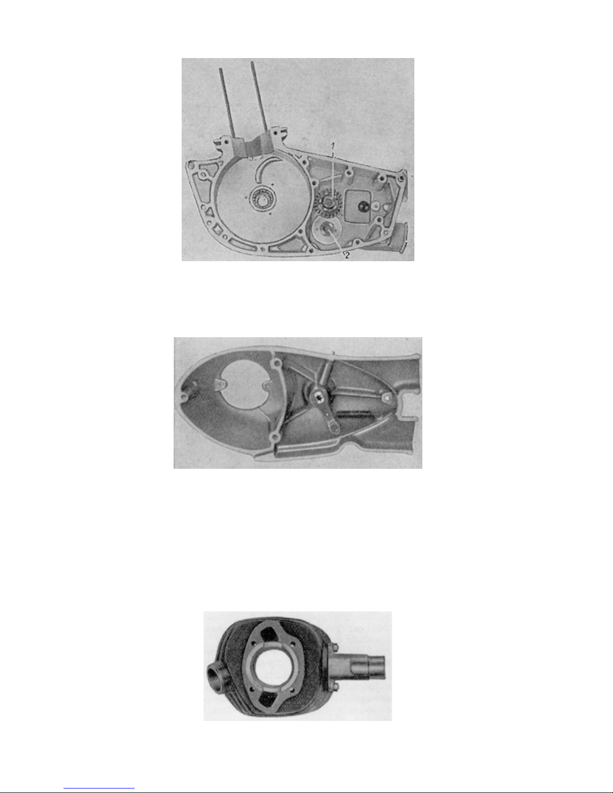
Image 9. Crankcase section
(1)Ratchet
(2)Bushing for countershaft
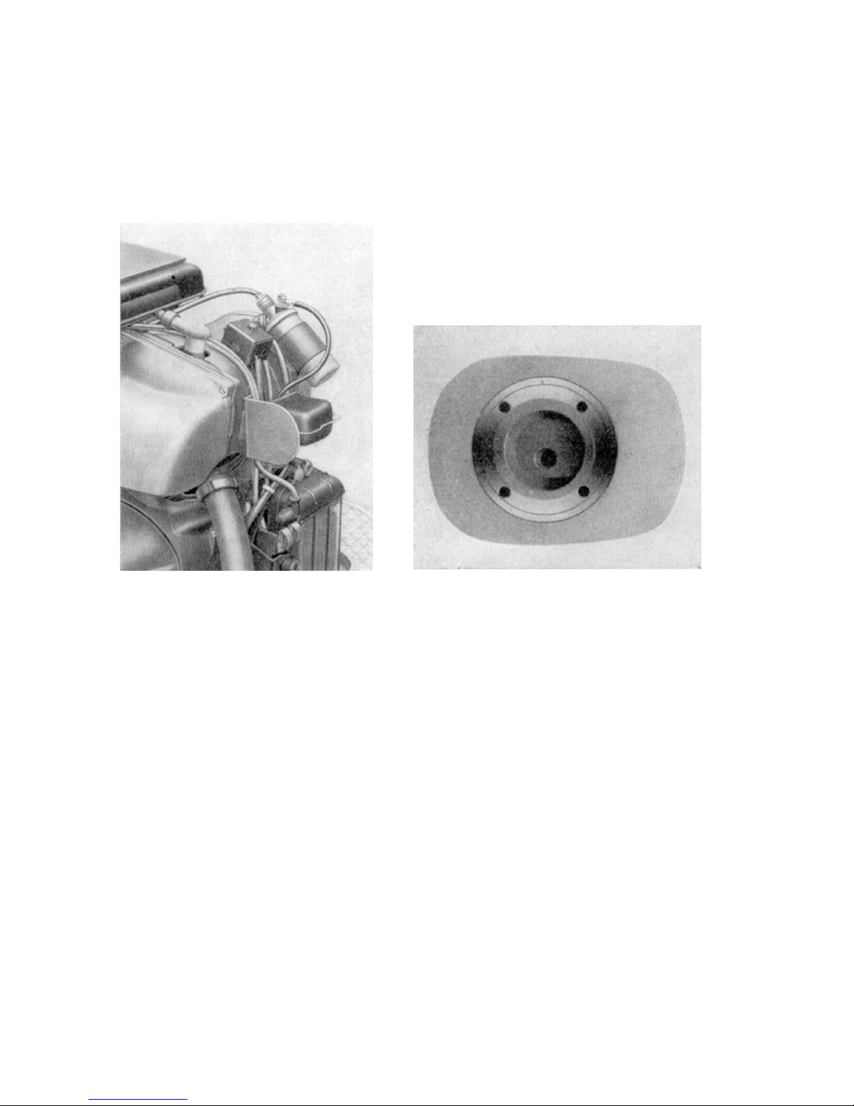
The main transmission of power including the clutch can be found in the left area while the
alternator and the clutch access are installed in right side, well protected from dirt.
Image 10. Lightmetal lid, right side
2.14
Cylinder and Cylinderhead
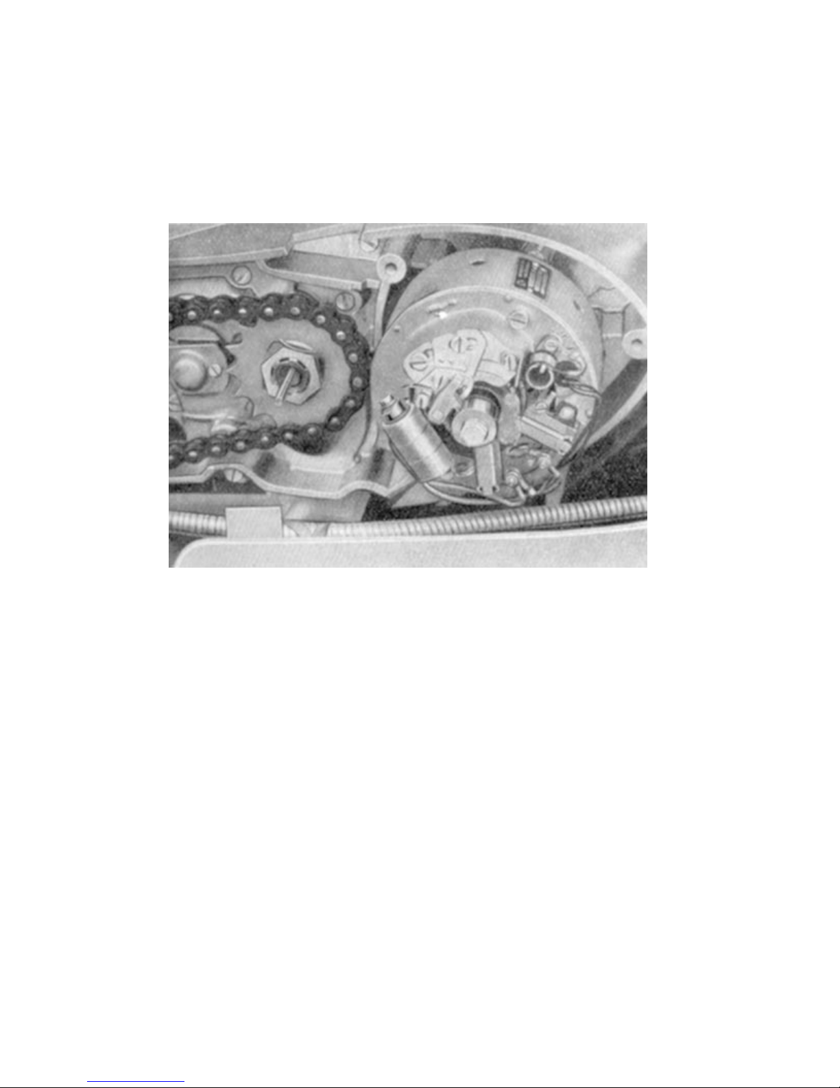
The cylinder is made of special grey cast iron and is covered with large scaled cooling fins.
Together with the cylinderhead which is also equipped with cooling fins, it is frimly screwed onto the
crankcase using four long special screws. At the foot of the cylinder a paper seal supplies the
necessary sealing.
Image 11. Cylinder
Page 19
Where the cylinder and the crankcaes meet, the crankcase is also equipped with some cooling
fins, to harmonize the optical impression of the engine.
Precisely carved, you will find the previously decribed (sect. 2.11, mode of operation) transfer ports
in the cylinder. The two port openings located on the sides at the foot of the cylinder are
corresponding with the adjacent ports in the crankcase. When the cylinder is worn out, it can be
rebored and fitted with the next larger size of piston. The measurements for reboring the cylinder
are as follows: 56,25; 56,50; 56,75 and 57mm.
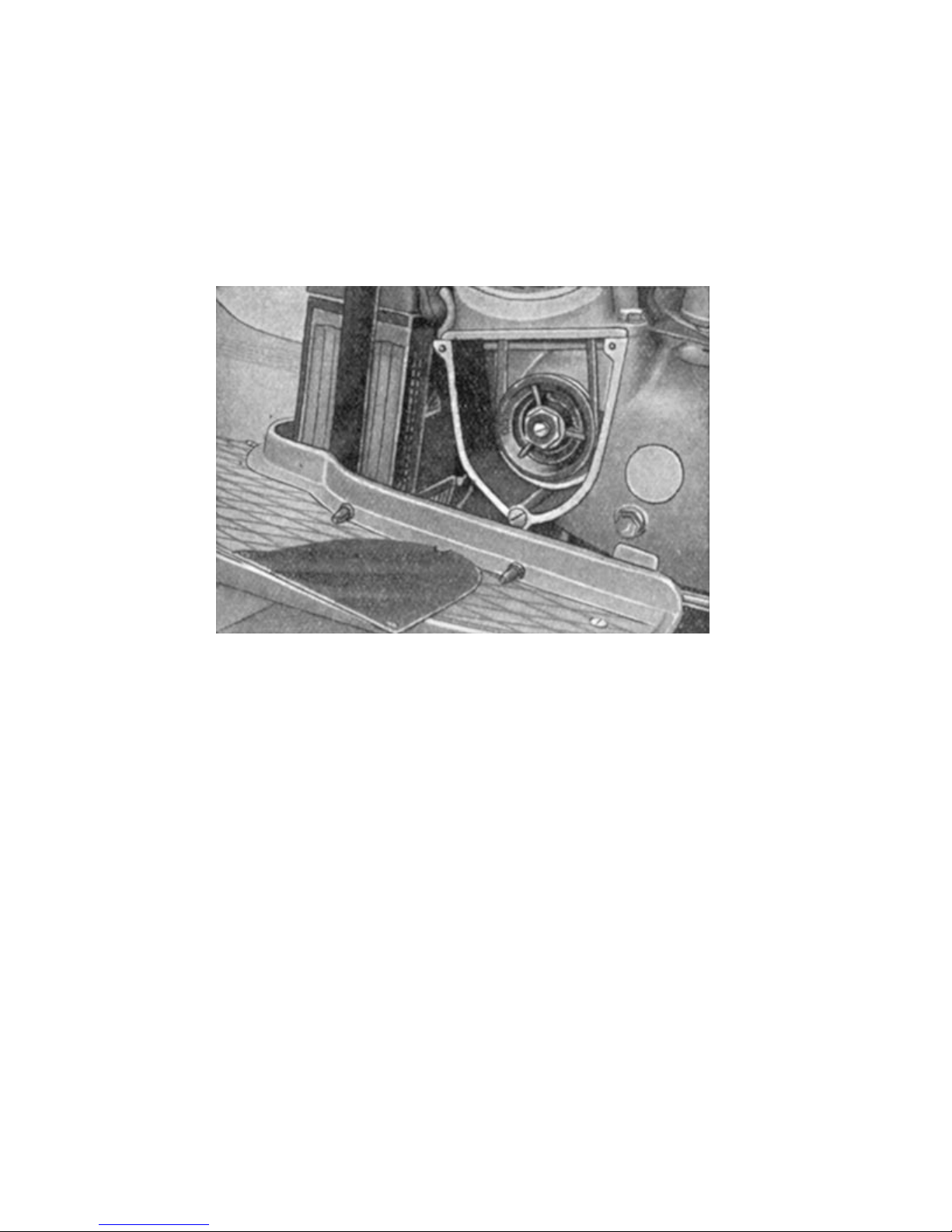
Image 12. Cylinder and Exhaust connectors Image 13. Cylinder head
A sparkplug that is necessary for the ignition of the gas/air mix, sits in the center of the cylinder
head. The cooling fins are oriented in direction of the supercharger blower.
Page 20
2.15 Piston and piston bolt
The purpose of the silicon bearing cast lightmetall alloy piston is to pick up the pressure from the
burnig fuel. The oscillation of the piston caused by the work cycles is transformed into the
necessary rotational movement by the crank. The sealing of the piston toward the cylinder walls is
achieved by the presence of two 2,5mm wide piston rings which are secured against rotating by
safety lock pins, to protect them from getting into the transfer ports, which could otherwise do harm
to the engine. The piston is connected to the crank by a specially hardened lapped piston bolt that
is secured against shifting by circlips.
Image 14. Orientation of aggregate, right side
2.16 Fan
An axial load supercharger forces fresh cool air onto the cooling fins of the cylinder to cool the
warm air that is being produced by the cycle process of the running engine. The axial load
supercharger is made from two components: a light metal fan casing and an air guiding cover that
directs the air.
The flywheel is driven by a 8x5x474 drivebelt. The drivebelt is hooked onto the left crank pivot
secured by a beltdisc. A supercharger alarm system consisting of a contact and an orange pilot
lamp on the right hand side of the instrument panel, supplies the appropriate control and security
incase of possible blockage or snapping of the belt.
2.161 Inspection of the blower beltdrive
The belt for the flywheel should be loosly streched. It should also easily put the flywheel into
motion. If fitted too loose, it will lead to the belt „throbbing“, bearing the danger that the belt will
make contact to the housing and thus be subjected to premature wear. Also when the belt is
installed too tight, it will show signs of premature wear, because the tension that occurs during
operation adds to the initial tension of the belt. This leads to excessive friction on the belt´s profile,
which will cause the belt to eventually snap.
It is hard to give an exact value for the tension necessary for the belt but it´s safe to say, that when
you can push the installed drivebelt in by about 1/3 of an inch, that the tension set is just about right
to achieve the longest endurance of your belt. By using distancing strips between the blowercase
and the clutch lid the right tension of the belt can be set.
Page 21
2.162 Changing the drivebelt
a) Removal of engine housing
b) Removal of alloy lid on the left half of the enginecase underneath the blower by unscrewing
the two upper and loosening the lower cylinderscrew.
c) Remove lower drivebelt disc (right-hand-thread) using a 19mm socket and remove disc.
Image 15. Belt drive
d) Unscrew the three screws of the guide rim and remove the guide rim. On the extenstion of the
guide rim you you have the flywheel and the drivebelt disc. Now you can install the new drive belt.
(A reserve belt is in the toolbox).
e) Repeat steps a) through d) in reverse order.
Page 22
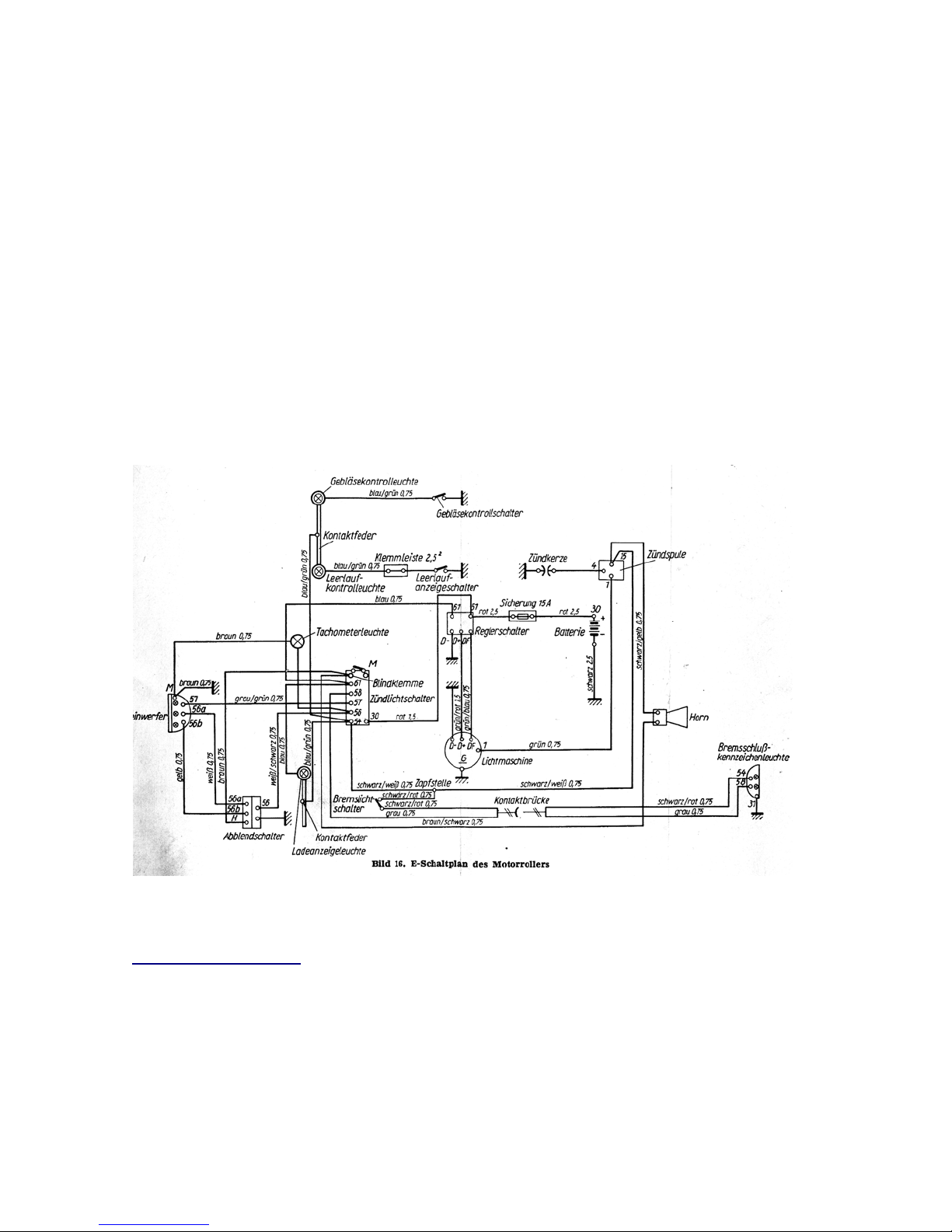
2.17 Electrical System
The electrical system consists of the following:
a) alternator 6V, 60W
b) Led-battery 6V, 8Ah (K20)
c) Ignition coil
d) Cntroller switch
e) Ignition and lightswitch
f) Circuit breaker and condenser (mounted on the holding cap of the alternator)
g) Sparkplug (in Cylinder head)
h) Headlight (Hi beam, low beam and parking light)
i) Charging control lamp (red, on the lefthandside of the controlpanel)
j) Neutral gear control lamp (green, on the lefthandside of the controlpanel)
k) Control lamp for Supercharger (orange, on the righthandside of the controlpanel)
l) Signal horn
m) Brake-, tail- and licenseplate lamp
n) Wiring harness
o) Control lamp (unused. Can be used for Hi-beam display for instance)
Image 16. Wiring diagram
Suggestion: A more detailed and colored version of the wiring diagram can be downloaded from
our website at
www.scooterstation.com
Page 23
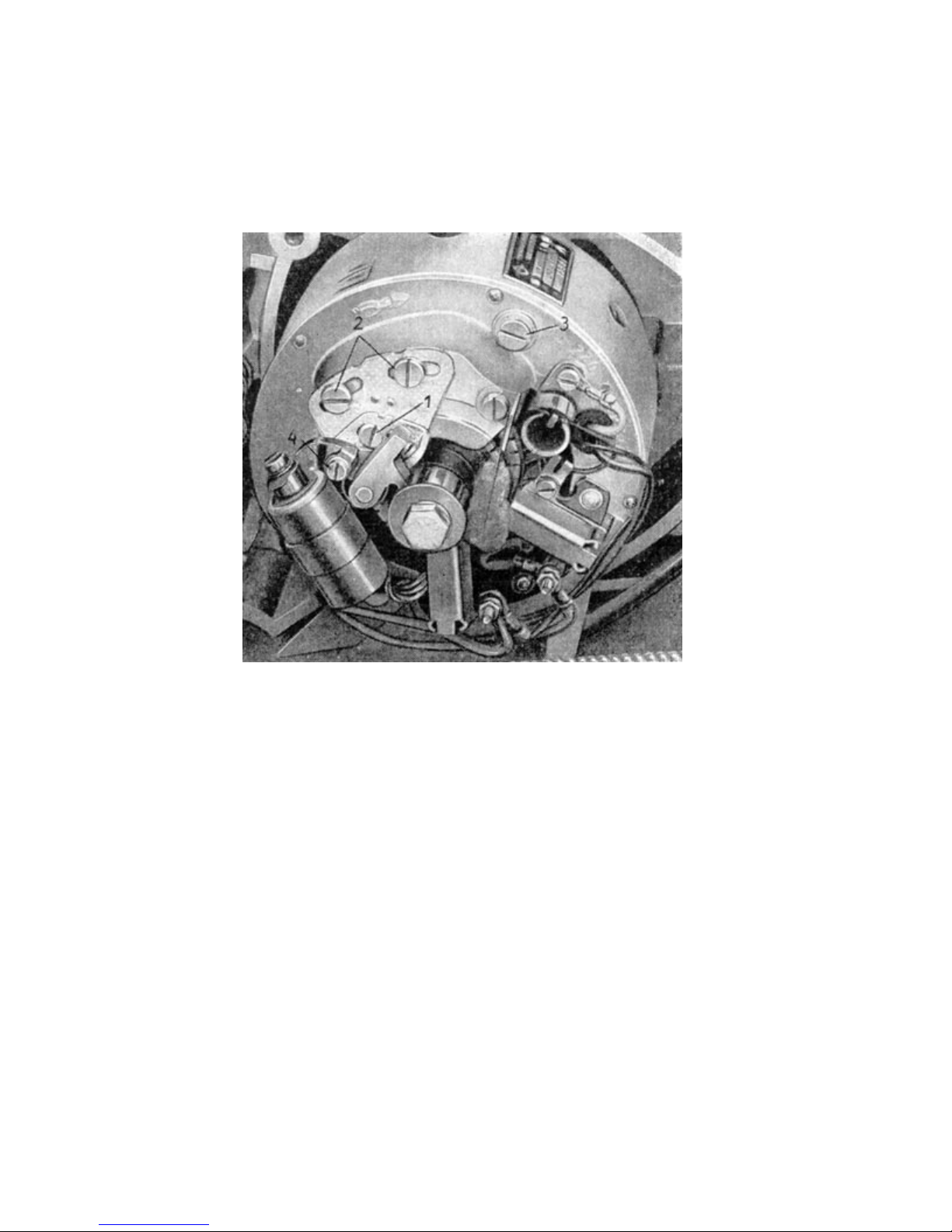
2.171 alternator
The genereator generates the electricity necessary for ignition, lights and signal horn. Also the
alternator charges the battery through a controller switch.
Image 17. alternator
The battery functions as a direct current shunt link alternator. The alternator is made from two main
parts. The anchor and the holding cap.
The controller switch is installed on the blowerhousing and keeps the alternators voltage steady,
regardless of the number of revolutions the engine is doing or how many of the lights are currently
turned on.
Also the controller switch automatically switches the battery off, when reaching a high enough
number of revolutions as well as switching battery support on when the revolutions fall under a
certain amount. When the red controll lamp on the controlpanel expires, the battery is being
charged by the alternator. When the red control lamp is on, it shows that the battery is currently
feeding the electrical system.
The anchor that carries the commutator, sits directly on the cone of the right crank pivot. It gets
screwed together with the circuit breaker cam using a long hexagonal nut. The holding cap contains
the pole housing with poles and field coils on the inside. The front face carries the circuit breaker
and the condenser as well as the brushes that are forced onto the commutator by springs and
supply the current. A three wired cable connects the alternator with the regulator-aggregate and the
circuit breaker with the ignition coil. The aeration of the of the alternator housing, wich is enclosed
by a housing lid, is achieved by a sufficiently large breakout in the partition wall of the housing. The
housing lid itself carries a little detachable plate, which if taken off the housing lid, enables easy
monitoring of brushes, condenser and commutator.
Page 24
2.171.1 Monitoring the electrical system
During regular operation the electrical system doesn´t need any extra attention. However it is
necessary to have the electrical system inspected and serviced by special personnell (IKA dealers
workshop) every 6.000 miles. Merely the breaker points should be inspected for abrasion every
1.000 miles.
When the cam is in it´s highest position, the contact gap should be 0,4mm. Less or more gap will
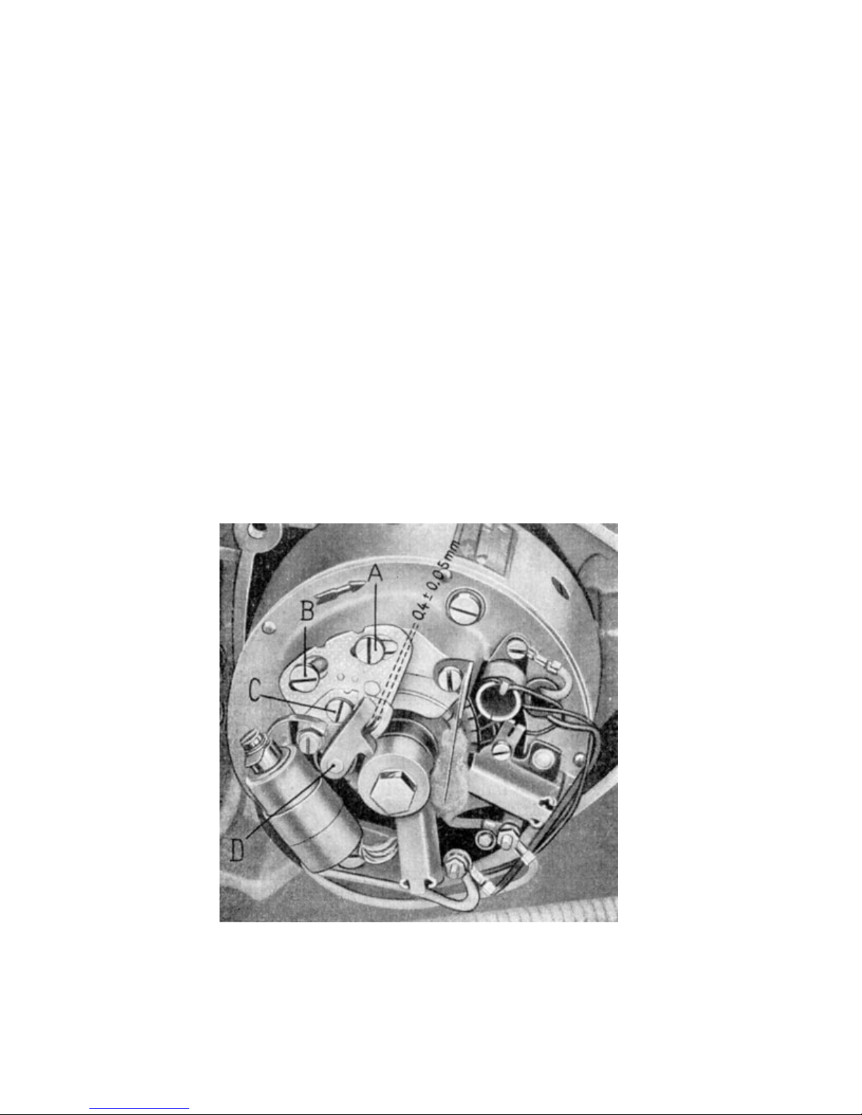
result in bad starting behaviour, unsteady running, less performance and higher gas consumption of
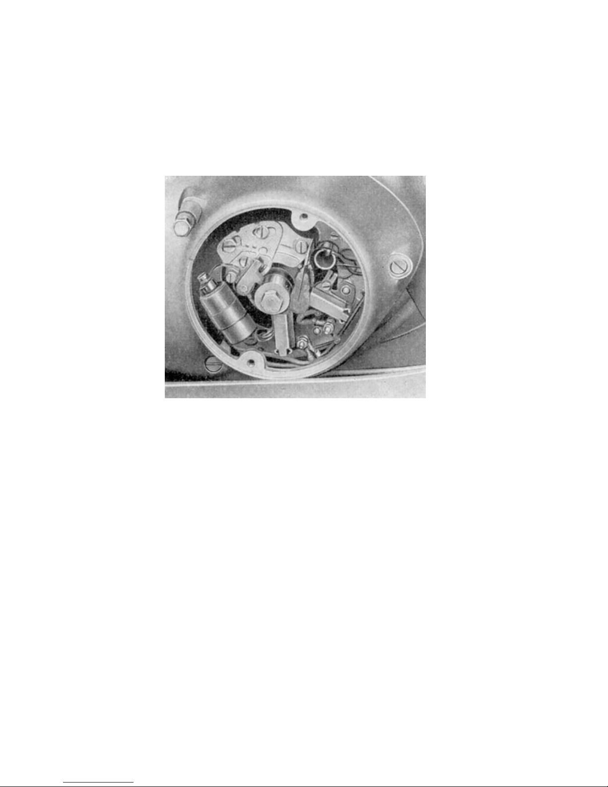
the engine. Adjustment of the points is done with detached circuit breaker cover (see image 18) and
loosened clamping screw ( C ), by pivoting the smaller statorplate around the bolt (D). The pan
head screws (A and B) are not to be loosened during this procedure.
The clamping screws ( C ) and (B) are to be tightened again after adjustment. If the breaker points
have burned spots, they are to be smoothed out using a contact file. More vigorous signs of
conflagration on the points indicate a defecticve condensor. The advice of a professional electric
technician is now essential to have the defective part replaced.
2.171.2
Electrical tuneup (every 6000 miles)
The regular 6000mile inspection of the electrical system consists of a check up on proper
positioning and insulation of the wiring and faultless seating of all clamping screws and
connectors. All contacts are checked for cleanness and are polished if needed. (This covers ignition
coil contacts, ground contact of the battery, regulator contacts, alternator contacts, tail- and
stoplight connecting contacts in the front of the rear housing and on the frame).
Image 18, Statorplate
The condition of the commutator and the carbon as well as the tension of the carbon springs will be
inspected. The positive (+) carbon´s wear is heavier compared to the negative carbon (-). The
lowest height of the carbon may not exceed 11mm. After reaching this height, the carbon should be
Page 25
replaced. Grind in a new carbon should be done by a professional mechanic. Letting the carbons
wear out too much, will braze out the coil connectors in the commutator. The generotr´s correct
power emission will be tested using high precision equipment. Also, the
condition of the circuit breaker (spring tension, lever bedding, breaker cam) will be inspected. The
grease cloth for the breaker cam should receive 2-3 drops of oil every 1000miles.
Further more, given the opportunity, the ignition timing will be adjusted, because it changes itself in
operation due to wear of the points. The correct position should be 4mm before TDC (Top Dead
Center of the piston).
This timing value has been identified as optimal during the extensive test phase and should not be
changed, because only this setting will ensure best performance and best gas mileage.
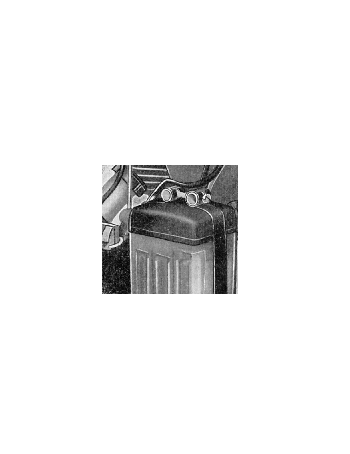
2.172 Battery
It is the battery´s task to supply any operational electrical equipment with energy, while the engine
is turned off. When the engine is running, it is being charged by the alternator. The amount of
charge adjusts itself depending on the battery´s energy level.
Picture 19, Battery
The Lead-battery has a maximum capacity of 8Ah (Ampere hours), assumed that the battery is
discharged at a rate of 20 hours with 5% of the nominal capacity, equaling 0,4 A.
With the outside temperature falling, the capacity of the battery secedes rapidly. This is why you
should always pay attention to the actual charging state of the battery especially in winter. Where a
battery on low charge freezes at about -15 degrees celsius (5 degrees farenheit) and possibly
breaks the battery case, there is no need to worry about freezing battery acid in a well charged
battery.
2.172.1 Battery maintenance
The battery is very important for the proper functionality of of the ignition and the lighting system.
The operative condition of your motor scooter and it´s engine is highly depending upon the
condition of the battery. Due to that fact it requiresregular attention.
In it´s first two weeks of operation, it should be recharged at an external battery charger twice,
because a new battery reaches it´s maximum capacity by and by. When in permanent operation, it
Page 26
is usually not necessary to recharge the battery at an external battery charger. It is however,
necessary to recheck the battery´s acid level every two months (or every 1200 miles) and, if
necessary refill the evaporated battery fluid with distilled water untill the plates in each cell are sunk
about a half an inch under fluid level. The battery contacts are to be kept clean, checked for good
contact and afterwards lubricated with Vaseline. About twice a year or once every 3000 miles –
one should have the acid concentration checked and possibly supplemented by a battery shop or a
local IKA-electric service station.
2.172.2 Battery is not being charged sufficiently
a) Acid concentration incorrect (volume weight at full charge: 1.285)
b) Acid level too low ( refill the evaporated battery fluid with distilled water untill the plates in each
cell are sunk about a half an inch under fluid level.)
c) Plates are damaged
d) Supply lines are loose or oxidized
e) Short circuit in the wires, mechanical defect in the stator plate, dirty commutator,carbons
disaligned, bad grounding of battery, regulator or statorplate.
f) Main cable between statorplate and regulator or ignition coil defective.
g) Regulator or reverse current switch defective.
Since we have often had to discover, that the battery was not installed correctly, we have to point
out explicitly, that the stator and/or the regulator will break if the wrong connector is attached due to
non-observance. (Positive pole points to the blower and is connected to the red cable, negative
pole points to the exhaust and is connected with the black cable.)
2.173 Light and signal system
The headlight is equipped with a 35/35W Bilux lamp for hi and low beam and a 1.5W lamp for
parking light. The lights can be switched on by turning the ignition switch on the left hand side of the
instrument panel.
The switch on the left hand side of the handlebar is used to switch from hi beam to low beam. Since
it is a combined switch, the signal horn is activated by pushing down that very same switch.
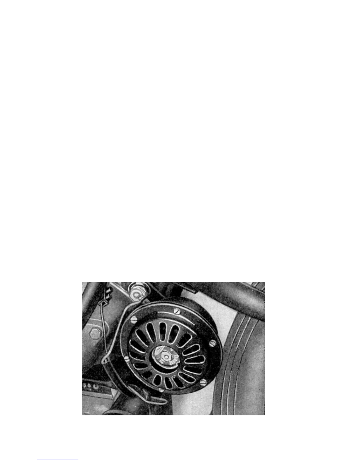
The signal horn can be found on the left side of the rear rocker and is maintenance free. The clarity
of the horn sound can be adjusted by turning the screw located on the back of the horn.
Image 20, signal horn
Page 27
A purposeful and yet shapely developed cap contains the lamps for brake light, taillight and
licenseplate light and is located at the rear end of the hood.
2.173.1 Signal horn failure
a) Defective horn
b) Broken contact (bad wire)
c) Defective signal switch
d) Battery empty
2.174 Voltage regulator
It is the regulators task, to keep the voltage on a constant level regardless of the engine speed or
the amount of operative consumers. The voltage regulator also contains the reverse current switch.
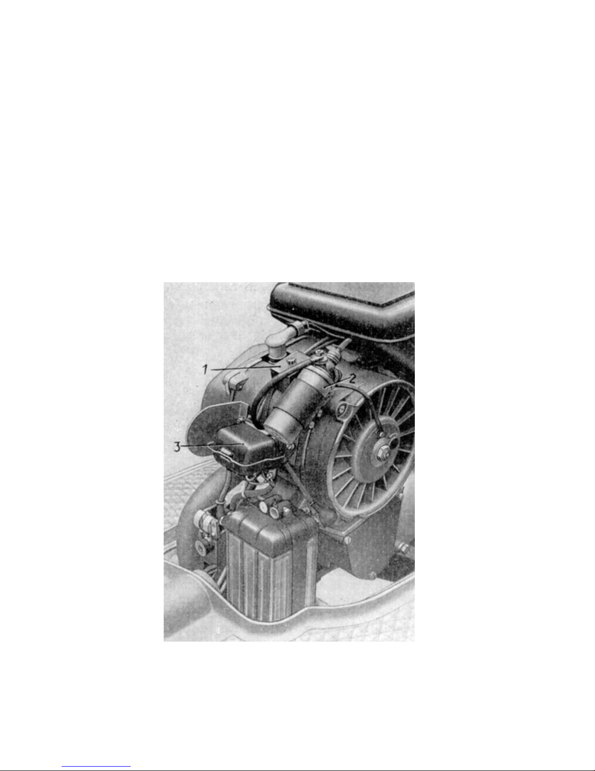
Image 21. voltage regulator and ignition coil
It switches the battery supply for the electric circuit off, when the engine produces enough power to
maintain all the consumers and back on, when the number of revolutions are not sufficient to supply
all needed power.
Page 28
2.175 Ignition
The ignition consists of the ignition coil, which is connected to the flywheel housing, the ignition line,
the spark plug and the circuit breaker with parallel switched condensor that are mounted on the
geneartor´s holding cap. The breaker cam wich rotates along with the crank causes the breaker
lever, that carries one of the circuit breaker contacts, to be raised against the pressure of the
breaker spring and thus causes the primary current to be interrupted while the contacts are
seperated. Just in this moment, the voltage that has been generated while the contacts were
closed
,
Image 22 circuit breaker
breaks down and inducts a high voltage of 10.000 to 15.000 volts. This high voltage flows through
the high voltage cable directly to the spark plug.
To prevent any damaging spark from bridging the points, a condenser is switched parallel to the
breaker points. To achieve the the right contact distance, which is at the highest point of the
breaker cam (0.4mm) and to set the best ignition timing (4.0mm before TDC), the two-pieced stator
plate is kept adjustable. A little lube-cloth, that is kept under spring tension keeps the cam´s
slideway slightly greased and thus reduces wear of the breaker lever to a bare minimum.
2.18 Carburetor and filter
Processing and conditioning the right mixture of fuel and air for combustion is maintained by the
BVF (Berliner Vergaser Fabrik, engl.: Berlin Carburetor Plant) 24 KN 1-1 Round slidegate valve
carburetor.
The fuel level inside the floater housing is maintained on an optimal balanced level of about one to
two mm under the discharge opening. This is achieved by the floater and the float needle valve. By
actuating the dabber on the floater housing, the floater is being pushed down and thus keeps the
float needle valve open. By doing this, the fuel floods at the needle valve opening and over enriches
the air / fuel mix that is needed for starting a cold motor. The fuel travels from the floater housing
through the main jet into the needle jet, who´s output opening can be adjusted as a result of it´s
conical design. The needle jet is installed in the gate valve (Actually a round slidegate valve in this
carburetor). It so has to follow the same movement as the slidegate, which is operated through the
throttle control on the right hand side of the handlebar. By opening the slidegate, air and fuel are
now equally and evenly distributed. Thereby always the correct combustible ratio of air and
fuel,which is necessary for
Page 29
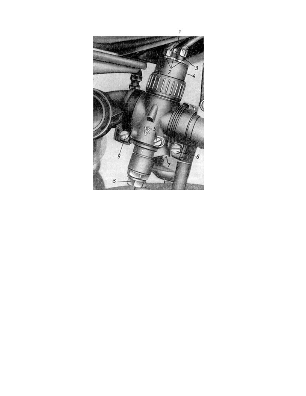
Image 23. Carburetor
(1)Cable adjusting screw
(2)Hexagonical screw
(3)Striker pin for idle adjustment
(4)Slidegate housing cap
(5)Idle regulation screw
(6)Hexagonical screw for retainer
(7)Idle jet
(8)Screw plug
(9)Hexagonical screw filter retainer
immaculate combustion, is getting distributed to the cylinder. The main jet also sets the maximum
tolerance for the amount of fuel, while the needle jet controls the fuel output up to appx. ¾ of the
slidegate opening. By manipulating the needle setting in the slidegate (notches in the needle jet),
additional influence can be taken towards the fuel/air mix consistency within the scope of the jet
needle (until appx. ¾ slidegate opening). If the needle is placed higher, the ratio will be richer and if
the needle is placed lower, the ratio will be leaner.
Incase of having to start a cold engine, the carburetor has an air slidegate installed, that can be
operated by using the air lever on the right hand side of the handlebar.
The fuel-air-ratio is set by an idle-fuel-jet (7) and an adjustable idle-air-jet that let fuel-air-foam pass
through a bore to the outside. Adjusting the idle speed is done by adjusting the striker pin (3),
which is located at the slidegate housing cap (4).
Page 30
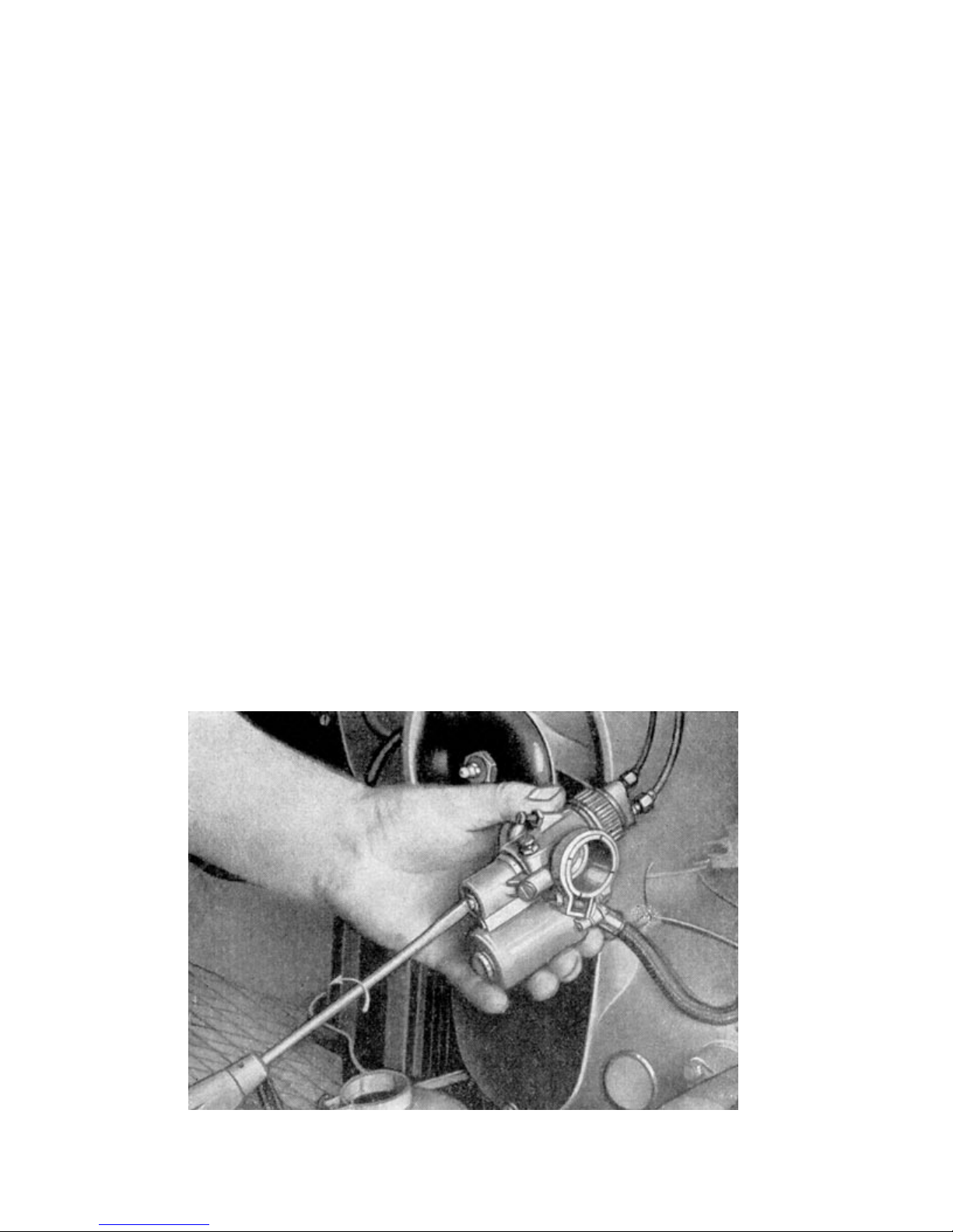
2.181 maintenance of the carburetor
The main jet can be cleaned without having to take the carburetor apart. All that needs to be
removed for that purpose is the screw plug of the mixing chamber. The main jet sits in the needle
jet. Loosen the clamping screw and turn the carburetor so, that the screw plug can be unsrewed
from the mixing chamber. Now the main jet can be removed using a screwdriver. The jets are
cleand by simply blowing through them or using a horses hair. Never use wire or needles for
cleaning attempts, because it might damage or break the jets alltogether.
The carburetor should be dismounted and disassembled once every 1200 miles. In order to do this,
the silencer needs to be removed along with the fuel line. Afterwards the cap of the mixing chamber
needs to be unscrewed and taken off with the throttle cable and connected throttle slide gate. Next
the carburetor´s clamping screw needs to be loosened and the carburetor pulled off from it´s
socket. After loosening the two screws that are attached to the floater housing, the lid can then be
taken off and the floater with needle removed.
To gain access to the needle jet and the main jet, the screw underneath the mixing chamber needs
to be loosened, using a hexagonical wrench. The needle jet is screwed into the body of the mixing
chamber and should, if possible, not be removed, because this might cause malfunctioning of the
carburetor.
All parts are to be cleansed thoroughly with fuel and then checked for mechanical defects (wear).
Wear and tear of things like loose parts of the carb, worn out floater needle or jet needle, defective
floater, damaged gaskets, bent jet needle or a loose or inclined intake socket are responsible for
poor function of the carburetor. Because one or the other of the above mentioned faults might occur
during regular operation of the scooter, it is advisory to have the carburetor thoroughly checked by
a dealer´s workshop every once in a while.
When assebling the carburetor, it is to be seen, that all the parts are tightened well, that no gaskets
are being damaged and that the needle jet isn´t being bent during installation. The standard setting
of the carburetor must not be changed under any circumstances, because the factory setting is
already optimal regarding gas consumption and performance. Before mounting however, one must
not forget that is is essential to lube the clutch spindle. (Nr. 9 of the lubechart, illustrations 59 and
60).
Adjusting idle speed is done by adjusting the idle airflow screw after first cleansing the idle fuel jet.
Unscewing the idle airflow screw in a counterclockwise rotation, leads to more air (a leaner ratio)
and screwing it in results in more fuel being provided, and thus a thicker ratio. Normally, the air/fuel
ratio is correct, when the idle airflow
Illustration 24, Removal of main jet
Page 31
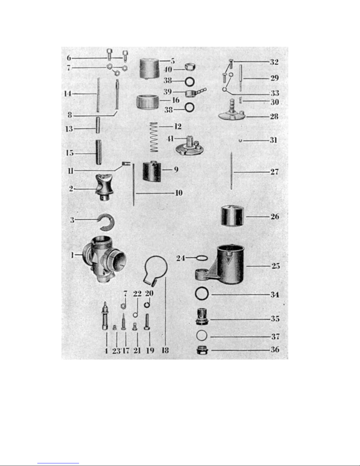
Illustration 25, Explosion diagram of carburetor
Page 32

Parts list for carburetor type 24KN1-1
(1) Carburetor housing, (21) Idle jet
pre assembled
(22) Seal for idle jet
(2) Thrust piece
(23) Main jet
(3) Seal for thrust piece
(24) Upper Gasket for
(4) Needle jet floater housing
(5) Slidegate housing cap (25) Floater housing
(6) Cable adjustment screw (26) Floater
(7) Hexagonal nut (27) Floater needle
1x for regulator screw
2x for cable adjustment screw (28) Floater housing cap
1x for stop pin
(29) Dabber
(8) Stop pin
(30) Pressure spring for dabber
(9) Slide gate
(31) Lock washer
(10) Needle
(32) Cheese head screw for floater
housing cap
(11) Clamping yoke
(33) Spring ring for cylinder screw
(12) Pressure spring for slide gate
(34) Lower gasket for floater housing
(13) Guide jacket
(35) Hollow screw
(14) Pressure spring for choke
(36) Locking screw
(15) Air slide gate
(37) gasket
(16) Screw joint
(38) gasket
(17) Adjusting screw
(39) nipple
(18) locking ring
(40) Locking nut
(19) Hexagonal screw for locking ring
(20) Lock washer for hexagonal screw
Page 33

screw is screwed out by about 2½ rotations. After adjusting, it´s position is to be secured with the
counter nut.
The idle speed is adjusted through a stop screw which can be found on the housing cap. This
screw is also secured with a counter nut. Screwing the stop screw in, reduces the intake opening
that is left open, when the throttle is fully closed reulting in reduced idle speed. Acordingly, the idle
speed is raised, by screweing the stop screw out.
To insure that only clean air gets into the carb, an intake silencer wet air filter is installed before the
intake opening. The wet air filter´s baffle is coated with oil which causes fine dust particles to stick
to the many little filter channels, resulting in throttleling the carburetor and thus reducing power
output of the entire engine. This is why regular cleansing of the wet air filter is essential as well as
re-coating the filter with motoroil, which is mandatory to achieve full effect.
2.182 Cleansing the airfilter
After having removed the three hexagonal nuts from the intake silencer, it´s lid can be removed.
The rubber seating inside the lid (filter seating) holds the wet air filter. It can be pushed out easily
without the use of any tools. Using benzine and a little help of an old clean paintbrush the airfilter is
now to be cleansed thoroughly. (Attention: Never use benzine as fuel )
Afterwards the air filter is coated with a little motor oil. Leave enough time to let excess oil drip off.
When done, press the air filter back into it´s seating and screw the lid back onto the intake silencer,
after also having cleansed it. (The intake silencer is made from aluminum pressure die cast)
To clean the intake silencer, it must be removed from the rubber connection nozzle, which itself is
clamped onto the carburetor socket and can only be removed, once the two tightning screws (wich
carry the fastening angles) on the clutch housing are losened. The intake silencer can be ground
off, although the screws are only losened and don´t need to be entirely unscrewed, because the
fastening angles have trenches embedded.
While refitting the intake silencer, it must be carefully monitored, that the breather rubber of the
alternator is properly embedded into the bottom part of the housing, otherwise the alternators
ventilation is jeopardized.
When driving in snow, ice, sandy or very dusty areas, the airfilter is to be cleansed more often. A
dirty air filter results in an irregular running engine, smothering exhaust, higher fuel consumption,
and bad performance.
The engine must never be used without air filter, because the carburetor setting is precisely tuned
to the throttleing effect of the air filter. Missing air filter results in a ratio, that is too lean and results
in loss of performance. Also fine particles of dust and sand will get into the engine, corroding the
contact surface of the cylinder and possibly breaking the engine´s bearings. With every airfilter
cleansing (every 1250 miles) one shouldn´t forget to lube the clutch.
Page 34
2.2 Power train
2.21 Primary transmission and clutch
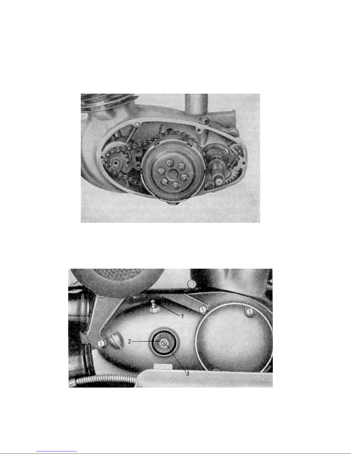
The power train between engine and transmission is achieved by a chain which sitting on the chain
pinion on the lefthand side of the crank extension on one side and on the sprocket wheel of the
clutch barrel on the other.
Chain transmission and clutch are operated in a constant oil bath, because the clutch
Image 26. Primary drive train
compartment is connected to the lube chamber of the of the transmission. Adjusting the primary
chain is not necessary.
A designated pressure screw (3) , which is secured by a counter nut (2) is used for adjusting the
clutch actuation. (See image 27).
Image 27. Clutch adjustment
(1) grease nipple
(2) Counter nut
(3) Pressure screw
Page 35
2.211 Adjusting the clutch
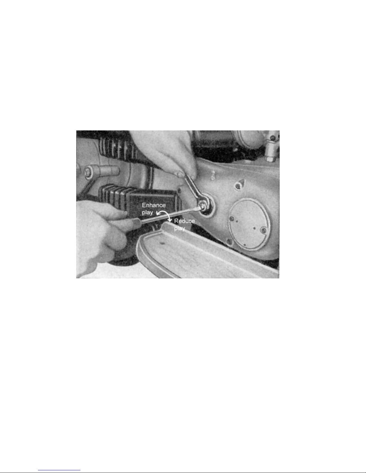
There always has to be a „dead gear“ of appx. 2-3mm near the clutch lever bowden cable seat.
If there happens to be too much play, the clutch can not be released entirely. If, on the other hand,
there is too little play, the clutch springs will be too loose, causing in the clutch to slip and in
extreme cases even to burn. The adjustment of the right play is done by turning the adjusting screw
on the right hand side engine housing. Before adjusting, the counter nut has to be losened applying
a 14mm wrench in a counterclockwise rotation. Then the play can be adjusted using a screwdriver.
Clockwise rotation reduces the play, counterclockwise expands.
Image 28. Clutch adjustment.
After adjusting, the counter nut has to be tightened while the screwdriver holds the adjustment
screw in place, to avoid it from turning along with the counter nut. However, since the introduction
of the new adjustment option located at the clutch lever on the handlebar, clutch play can now be
adjusted much easier making it more convenient too. (Also see handbreak adjustment)
Page 36
2.22 Gearbox
The for pairs of cogwheels that are sitting on the main gearshaft (clutch shaft) and the layshaftare
constantly engaged. All the gears as well as neutral (inbetween the 1
st
and 2nd gear)
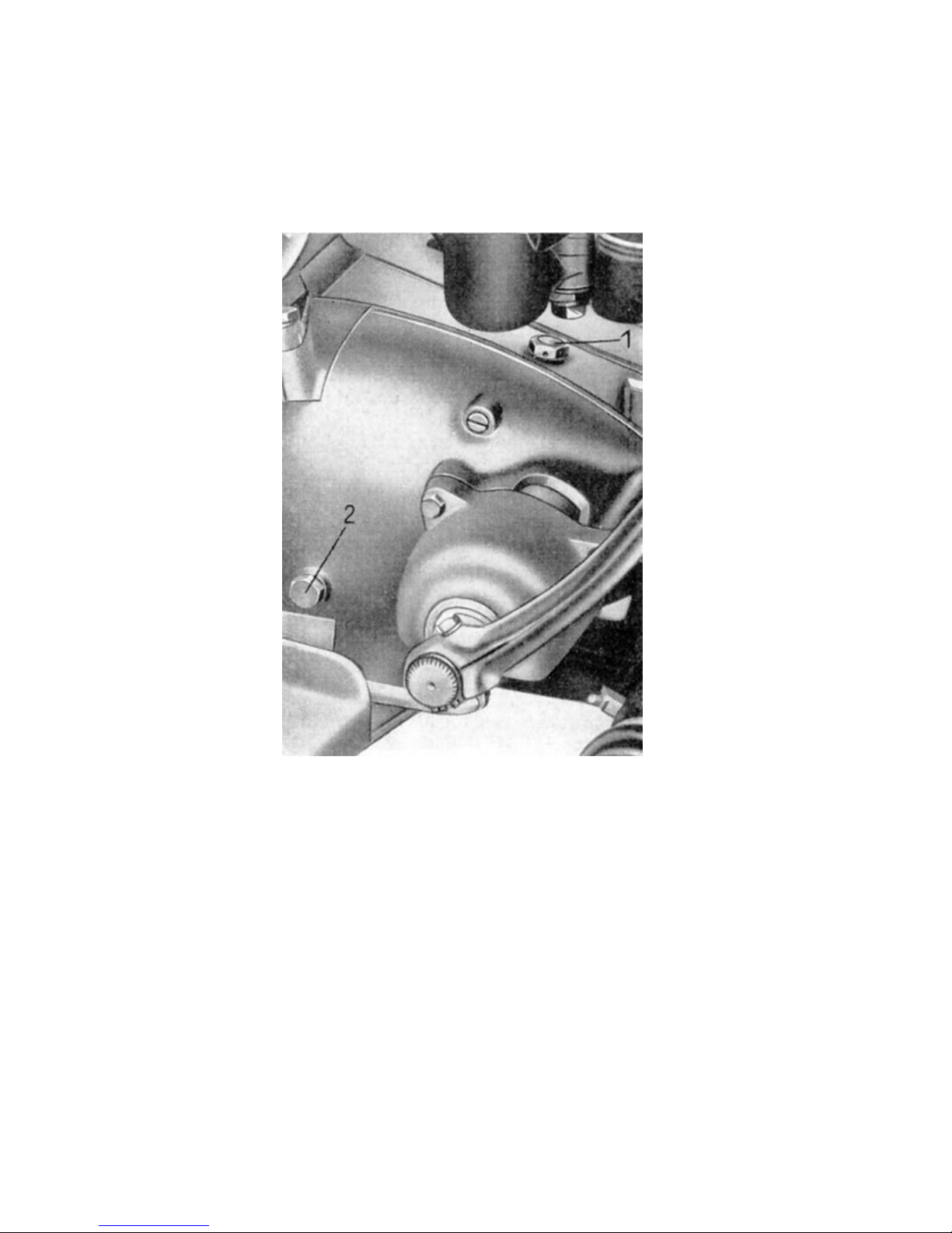
Image 29. transmission oil filling screw (1)
Level check screw (2)
are engaged through use of the hand controlled clutch.
The bearing of the main gearshaft is handled by ball bearings, and the layshaft´s bearing by bronze
bushings. A shaft gasket is placed on the shaftwheel (cogwheel on the right hand side of the
transmission, which´s hub is carrying the chain pinion gear on it´s outside.), to avoid oil leaks.
The switch for the neutral gear control lamp is installed on the wall of the gearbox housing next to
the cogwheel. In neutral the contact is closed, so that the green control lamp on the instrument
panel lights up. Lubrication of the gear box and the primary drive train is maintained by first opening
the transmission oil filling screw and then filling the gearbox with transmission oil.
To check the filling level of the gear box oil, a level chaeck screw is installed. When unscrewed, oil
starts to leak out of the opening, as soon as the oil level is correct.
The oil should be changed and flushed after the first 300 miles. After that chganging and flushing of
oil should be done every 6000 miles. Use summer motoroil as lubricant for the gear box. (Total
filling 450cm³)
Page 37
2.23 Rear power train
The power train from the transmission to the rear wheel is achieved by a roller chain which is
installed on the chain pinion gear at the gear box on one side and on the rear wheel´s sprocket
wheel on the other. A specially designed full encapsulation is provided, to enhance the durability of
these parts. The cycle of the roller chain from pinion gear to sprocket wheel is kept oil- and
dustfree by a special hose shaped two piece rubber housing.
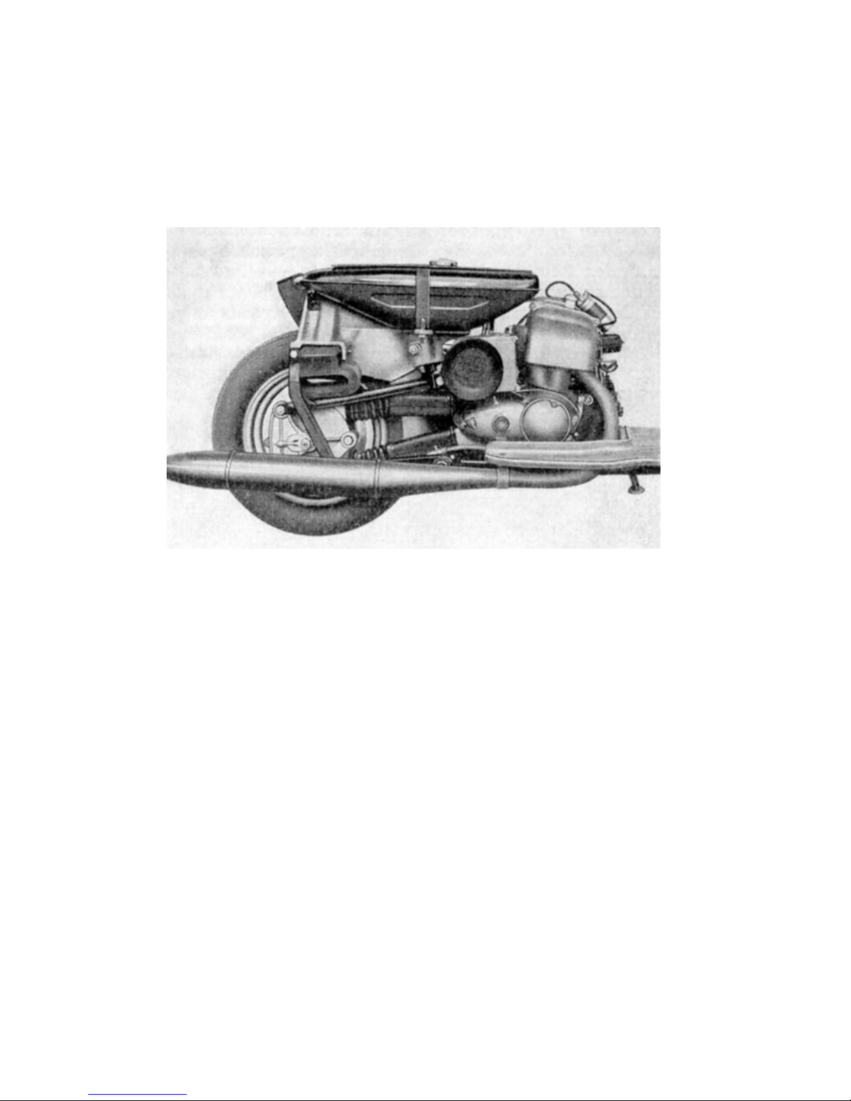
Image 30. Secondary drive train (transmission / rear wheel)
The tension of the roller chain and the rear wheel alignment is adjusted by commonly known chain
tighteners that are attached to the rear fork.
2.231 Chain maintenance
The chain should be lubed once every 600 miles, using viscous motor oil which can be applied
through the little drilling in the rear end of the chain housing, after the cap screw has been removed.
For this task, the rear wheel should be rotated slowly.
However, a thorough cleansing of the roller chain especially of the inner joints, is necessary every
3000 miles. To do this, the chain is to be taken off and thoroughly washed in fuel. (chain links
should be bent to extricate the the gunk from the joints). After washing the chain, it should be
bathed in heated, fluid grease. The chain must be removed from the cooled off bath in time, so that
a little excess grease clings to the chain, making it slide nicely within the rubber
Page 38
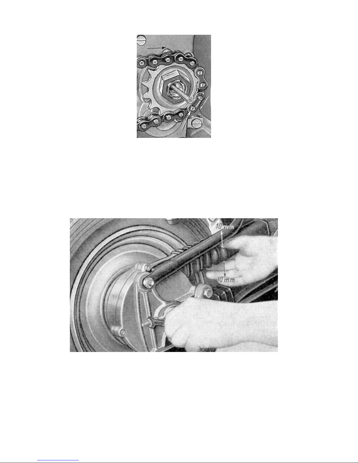
Image 31. Installing the master link
housing. After having removed the engine cover and the master link, it is advisable to leave the
rubber housing on the chain to not complicate the refitting process. Rather, the entire chainbox
should be removed and disassembled from the rear wheel hub, so that the chain can be refitted
nicely and fed through the rubber housing. Make sure, that the rubber flaps, which are attached to
the rubber housing are facing the vehicle.
When closing the chain, it is to be made sure, that the master link´s closed end is facing running
direction.
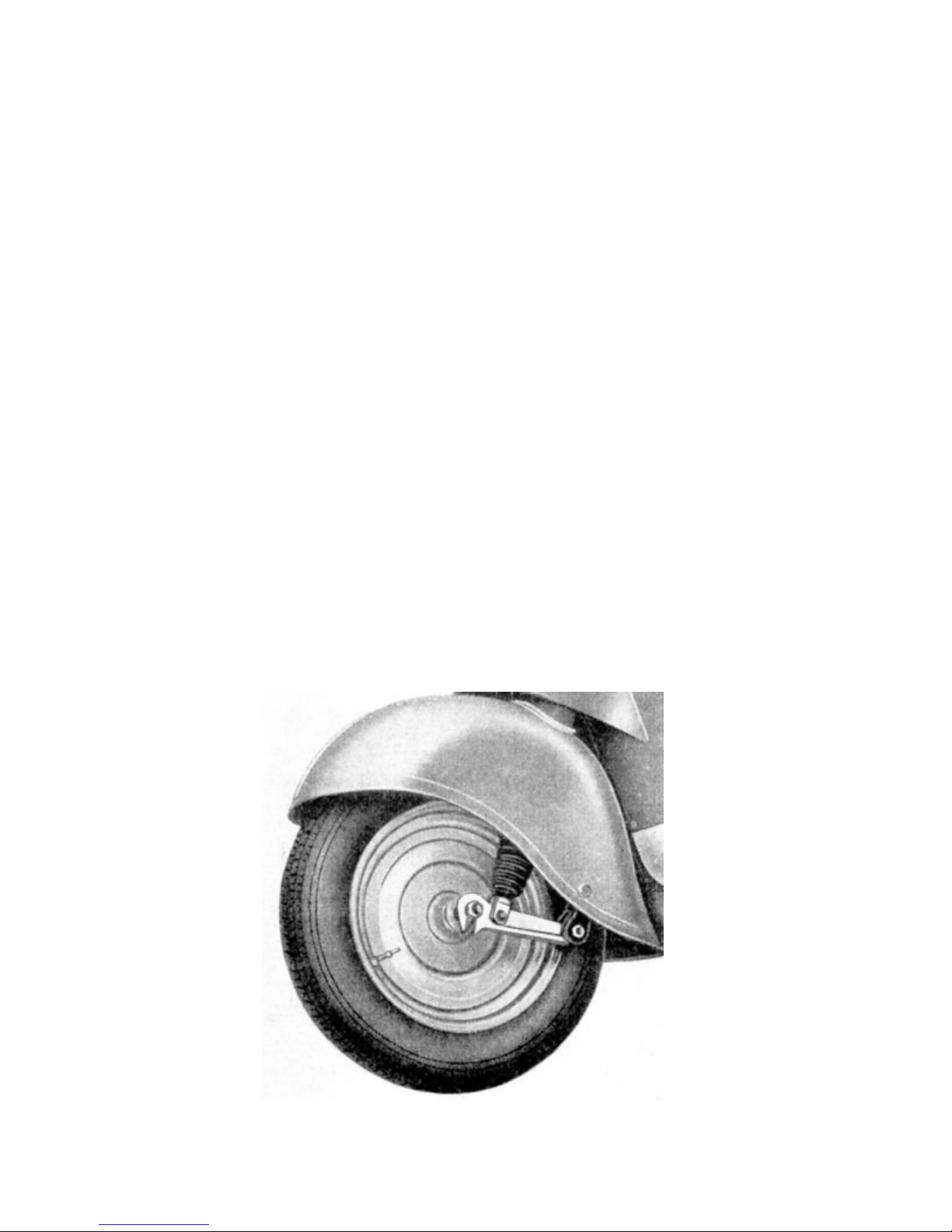
Image 32. Testing chain tension
The correct slack span is to be checked regularly. When measured in the middel of the chain, it
should sag by appx. 20mm. That means, it should shuttle 10mm up and down. If the slack span
should have more or less play than recommended, the chain, the rubber housing and the attached
sprockets and bearings will wear out early. Also an unnecessary loss of performance is caused by
improper slack span. Therefore it is recommended, to losen the axle nut and rod by two rotations.
Both of the front nuts of the chain adjuster are also losened by a few threads and threaded forward.
Now the two rear nuts of the chain adjuster are also to be threaded forward, until the slack span is
right.
Page 39
CAUTION: To prevent disalignment, the amount of threading must be equal on both
nuts.
Subsequently the chain adjusters are arrested by the front nuts and the axle nut and rod are also to
be tightened again.
It is extremely important to ensure exact wheel alignment, because not only does it assure good
road holding and thus the driver´s safety, but also it determines the life span of the chain, wheel
bearings and tires.
2.3 Chassis
2.31 Frame
the main part of the chassis consists of the central frame, that is made from electrowelded steel
pipes.
The rear end of the frame bears the rear axle and the hood mounts for fuel tank- and rear hood.
The engine is installed in the bracket and secured with three threaded bolts, nuts and locking
plates keeping it in place.
2.32 Front wheel balance beam fork
An improved edition of the balance beam fork retains the front wheel and carries the suspension.
Street impacts are conveyed through the swinging arm, the suspension pickups and the spiral
springs, which are guided by sliding bushings in the fork pipes. Sleeves located between the sliding
bushings and fork pipes seal the suspension mechanism against dust. The steering column is held
by two ballbearings that are sitting in the steering shaft and can be adjusted by counter nuts. A
steering clamp, that consists of two shells, that are kept toghether by clamping bolts
Image 33. Front wheel balance beam fork
Page 40
that are secured against contortion, are the link between handlebar and steering column. The
handlebar can be put into tha most convenient position for the driver, by simply loosening the upper
clamping bolt.
2.321 Disassembling the balance beam fork
1. Remove speedometer spring and brake cable.
2. Remove axle nuts and take out front wheel.
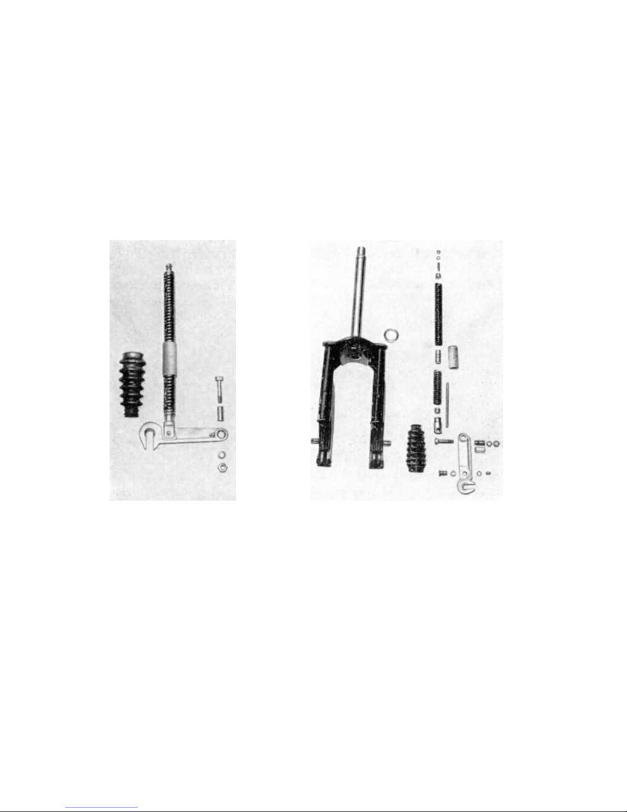
Image 34 and 35. Disassembled front suspenion
3. Loosen steering clamp and remove handlebar from steering column.
4. Remove sleeve from steering column and unscrew counter nuts.
5. Remove front fork including front fender from steering shaft.
6. The fender can be removed, by unscrewing the two fender screws on the sides of the
fender.
7. Push sleeves out of fork pipes.
8. Unscrew both screws fom the fork bridge.
9. After having removed the swinging arm bolts, the entire suspension including
swinging arm can be pulled out.
10. Swinging ar can be seperated from suspension pickup and connecting rod by first
removing the connecting rod´s bolt.
Page 41
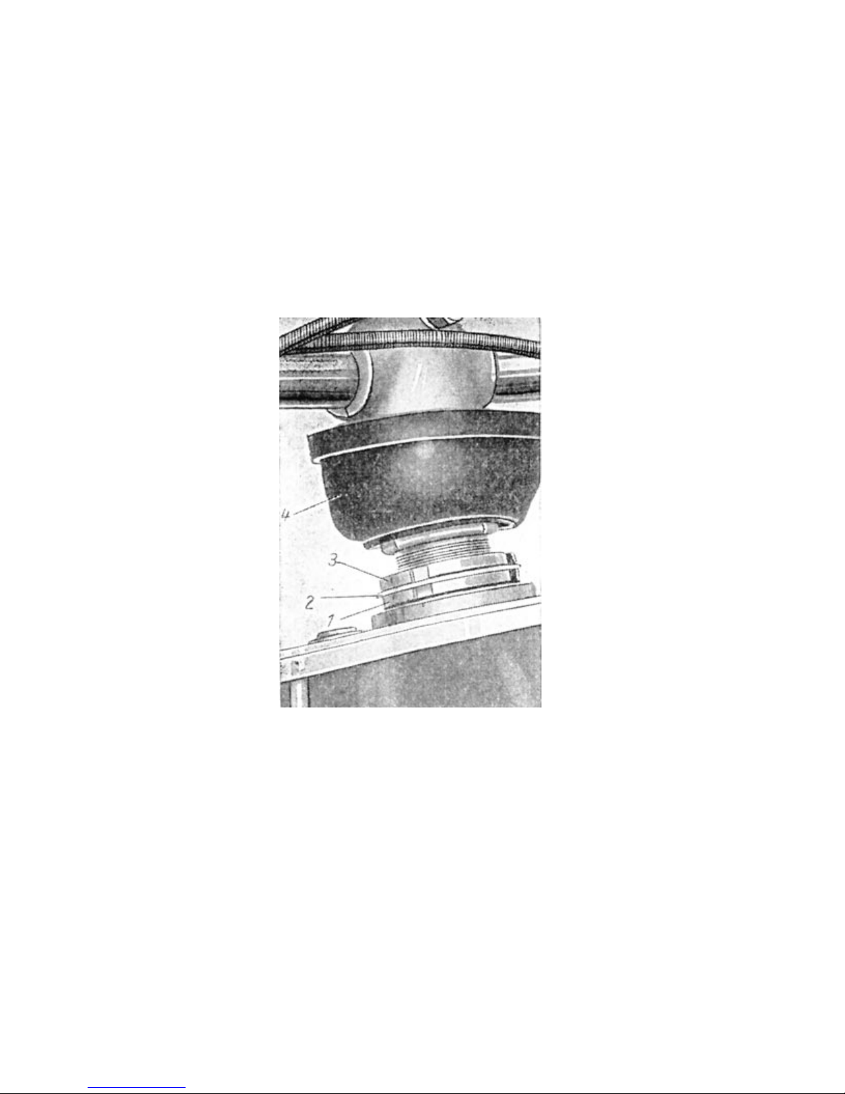
2.322 Adjusting the Steering column bearings
1. Bend rubber sleeve (4) back and open counter nuts (1 & 3) with hook spanner.
2. Tighten lower nut (1) until the bearing has just enough room to maneuver without
play.
Test: The fork should fall from it´s center position to the left and the right as far as
it will go without any interference.
3. Counter upper nut against lower nut. The locking plate (2) must be in place between
the two nuts.
Image 36. Adjusting the steering columns
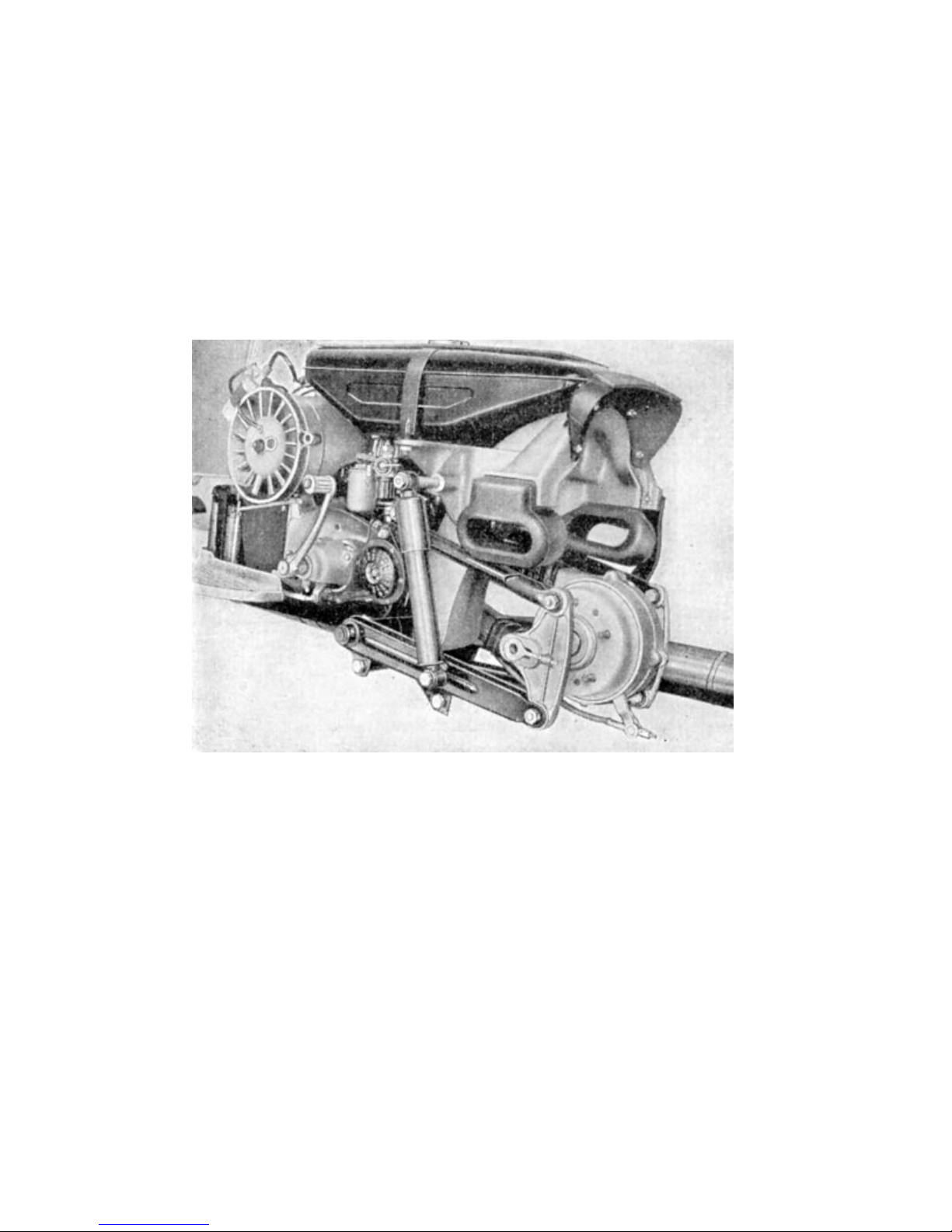
2.33 Rear wheel suspension
The rear wheel suspension is realized by a torsion spring, hydraulic shock and a trapezoid rocker.
The stability of the trapezoid rocker system is achieved by a stabilizer which is installed just behind
the torsion spring and is screwable into the swinging arm. The two pressure casted aluminum axle
holders that are each connecting each sides upper and lower rocker also carry the axle bearings for
the rear wheel. The axleholders are beared springy by rubber bushings and thus are maintenance
free.Rubber buffers are installed on both sides of the hood brackets, to prevent the suspension
from striking through.
Page 42
2.331 Disassembling the rear wheel suspension
1. Remove rear wheel (see section 2.351)
2. Remove rear hub with chain drive (see section 2.341)
3. Remove axle retainer by unscrewing the rear swinging bolts
4. The upper swinging arms can be removed by removing the long hexagonal at the
rubber bushing.
Image 37. Rear wheel rocker
5. Remove hydraulic shock.
6. Losen stabilizer by removing hexagonal nuts.
7. Remove lock rings from torsion spring
8. Using a hammer and a mandrel, the torsion spring can now be hammered out of its
sprocket seat. Caution: This task needs to be performed with great care, to avoid
damaging of the sprockets.
Page 43
2.34 Brakes
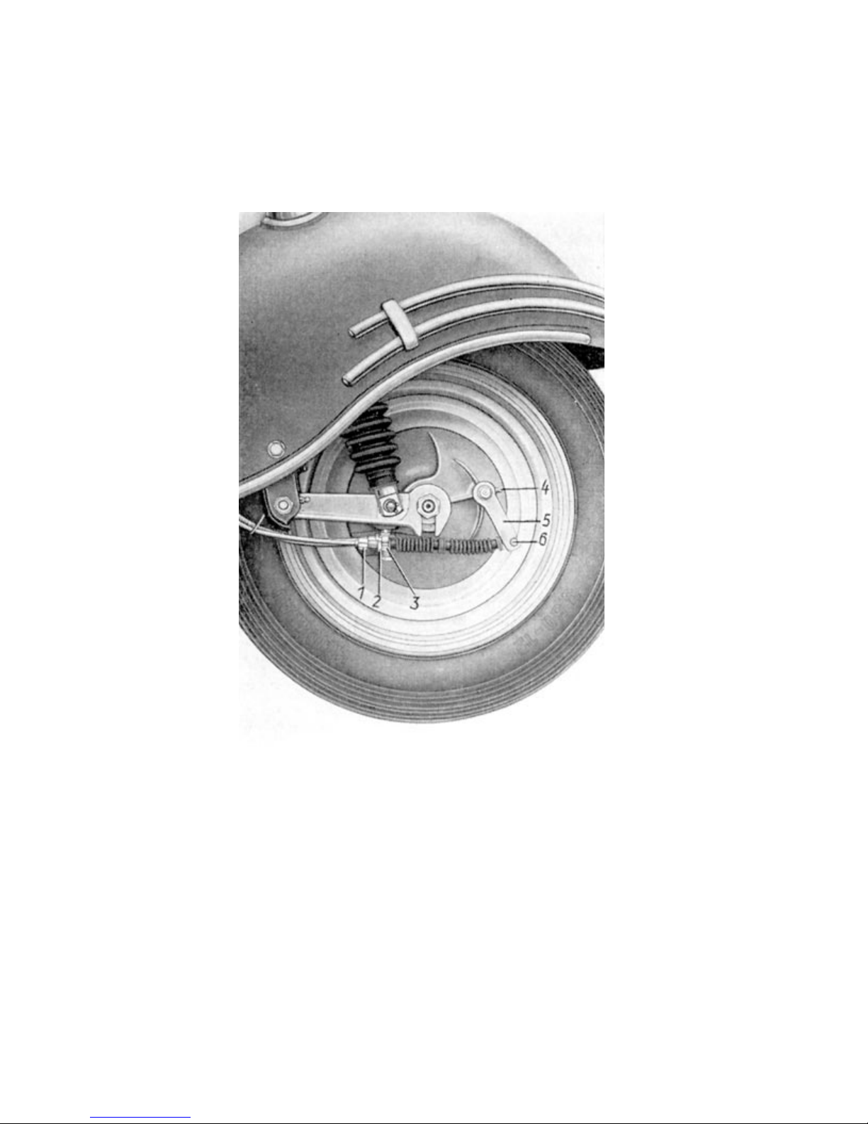
Mechanical brakes are installed in the front and the rear wheels.
Image 38. Front brake
(1) Adjusting screw (4) Lubrication nipple
(2) Counter nut (5) Brake lever
(3) Break anchor cam (6) Brake cable nipple
The front wheel can be adjusted, at the cable jacket on the handlebar or at the hub. The rear wheel
brake is adjusted by turning a hexagonal nut, that is sitting on the thread at the end of the brake
cable.
The bearings for the brake key shafts are equipped with lubricating elements to ensure smooth
running of the brakes, by keeping the bearings constantly lubricated.
Page 44
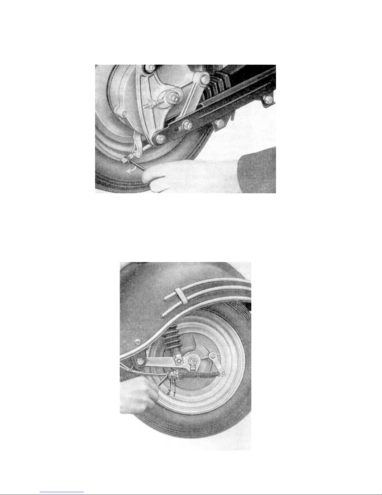
2.341 Brake maintenance
There are adjustment devices installed at the end of the rear brake cable and at the thrust bearing
Image 39. Adjusting the rear brake
of the jacket of the front brake for the necessary adjustments that need to be done due to the wear
of the brake shoes.
The rear brake is adjusted merely by clockwise rotation (½ rotation at a time until snap) of the
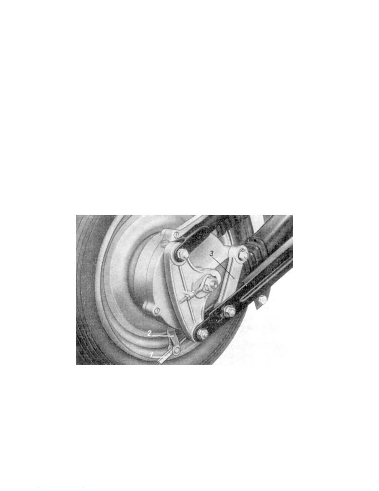
adjustment nut.To adjust the front brake, first the hexagonal counter nut needs to be loosened
counterclockwise. Then the adjustment nut also needs to be turned counterclockwise. Afterwards
the counter nut needs to be tightened again. The same procedure should now be done at the brake
lever.
Image 40. Adjusting the front wheel brake
Page 45
Do not over adjust. Make sure that the wheels turn without the brakes grinding after adjustment.
Brake drums should be opened every 3000 miles, to clean the inner parts of the brakes. The
armature plate with brake pads and straddle mechanism can be pulled out after first having
removed the front wheel. This task is a little more difficult for the rear brake. After having taken out
the rear wheel, rubber housings of the chain need to be removed from the cover plate and taken
off. Then the master link of the chain is to be opened (Make sure to leave the chain in the rubber
housings). After loosening the axle nut and the brake retainer screw, the entire rear wheel hub
including chain and rubber housings can be removed. The three screws of the chain housing are
taken out and the housing lid removed. The sprocket wheel is pulled out after the three nuts have
been taken out. Afterwards the armature plate can be pulled out, revealing the brake mechanism.
By removing the three countersinks, the brake drum can be removed.
All inner parts are to be thoroughly cleansed, the brake pads checked for wear and immaculate
adhesive sealing as well as the right bevel on their ends. All pivot points and spring loops are to be
lubricated ever so slightly.
Simultaneously the hub´s ball bearings are to be washed out in fuel and regreased afterwards.
2.35 Axles and wheels
The front axle is a regular axle with „drop out“ ends. The rear axle is a simple rod axle. The front
and rear axles are equipped with two ball bearings each. The speedometer is actuated from the
front hub through a helical gear and a shaft drive. The rims are designed as full disc
Image 41. rear wheel brake
wheels and are made from light alloy. The 2.50 Cx12“ drop base rims are mounted with 3.50-12“
tires. The five hole wheels are exchangeable from back to front, meaning that the rear wheel can
also be used as front wheel and vice versa.
Page 46
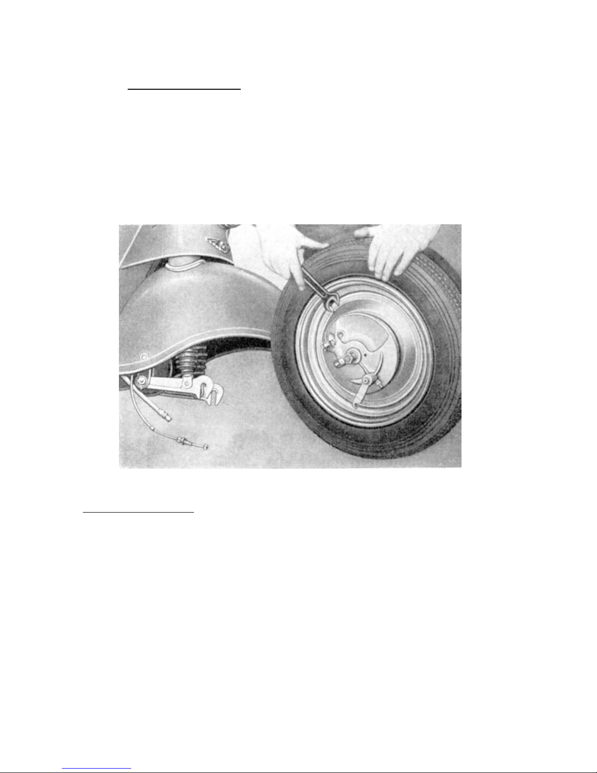
2.351 Flat tire
Removing the front wheel:
a) Tilt the scooter sideways and let it rest on the edge of the florboard.
b) Remove speedo cable and brake cable from the armature plate
c) Loosen axle nuts
d) Remove wheel
e) The wheel will be ready for tire installation, after having removed the five wheel
nuts.
Image 42. Removing the front tire
Removing the rear wheel:
a) Remove hood. (Screw of knurled screw and the two nuts)
b) loosen wheel nuts and rod axle
c) Tilt the scooter sideways and let it rest on the edge of the florboard.
d) Unscrew rod axle.
e) Remove bushing and unscrew wheel nuts
f) Remove rear wheel
Page 47
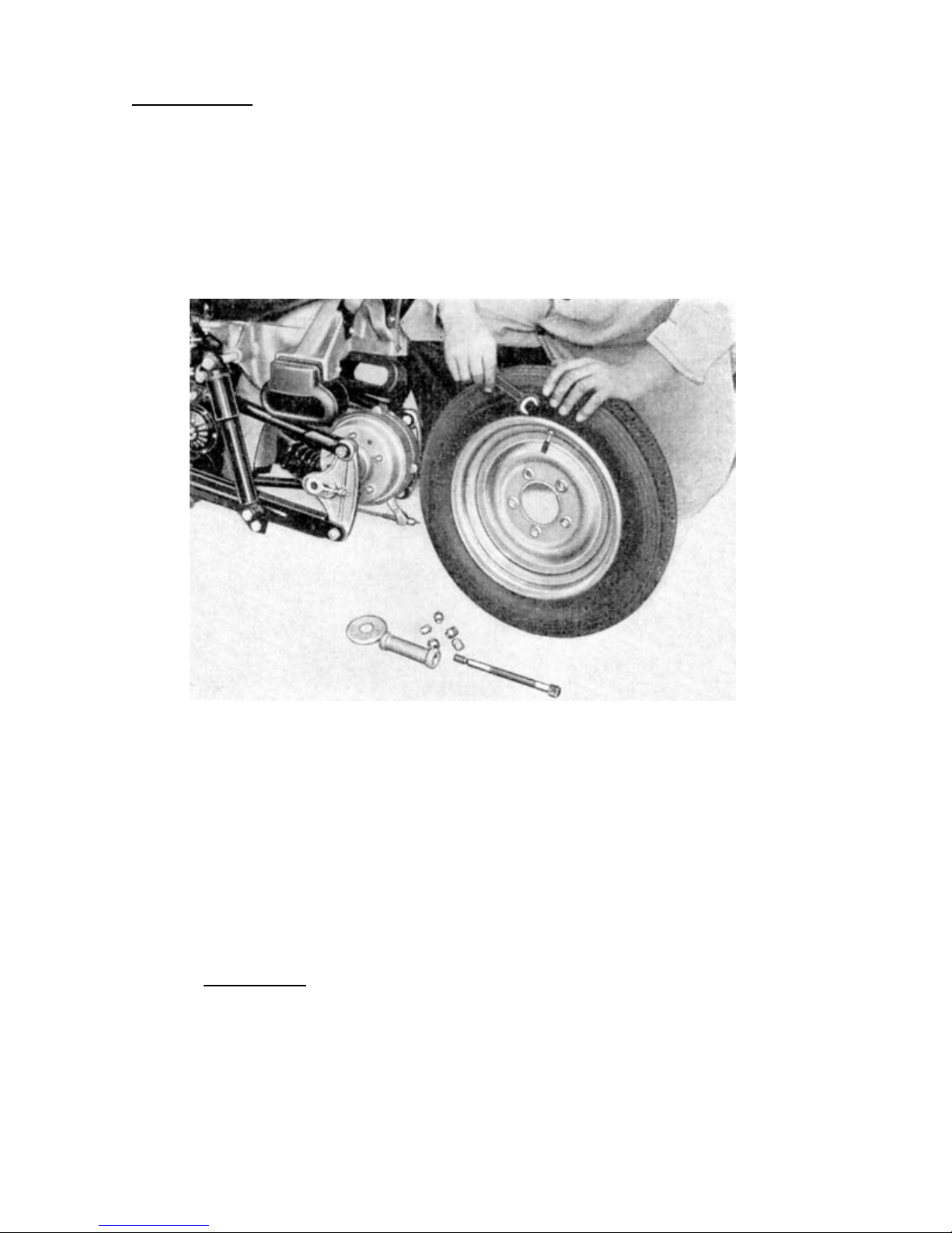
Dismantling a tire
1. Remove valve from tire and let all the air out
2. Remove nut from valve seat
3. Lay wheel down flat on the ground
4. Using both feet, step on the tire on the opposite side of the valve, until the tire is
pushed into the drop base of the rim.
Image 43. Dismantling the rear wheel
5. Lift the tire over the edge of the rim where the valve is located, using the provided
mounting levers (included in tool kit).
6. By moving the two mounting levers towards both sides, start lifting the rest of the tire
over the rim. Never apply brute force or use an oversize mounting lever without
making sure that the opposite side of the tire is completely pushed into the drop
base. Otherwise, the cable inside the tire might burst, resulting in a broken tire.
7. Remove tube
Mounting a tire
1. Perform a thorough check of the tire, to insure that there is no glass or other objects
driven into the tire. Also remove all dirt or sand from within the tire.
2. Disperse a little talc into the tire and spread by turning the tire.
3. Check canvas for proper positioning withing the rim.
Page 48
4. Fill the rim with a little airand place it into the tire so that the valve seat can be
pushed through the valve opening in the rim. Be careful to not twist the tube and
make sure that the valve sits straight. Loosely fit the valve nut onto the valve, so
that it won´t slip back into the rim throughout the mounting process.
5. Slip the tire over the rim´s edge on the opposite side of the valve. This can be done
without tools for over half of the rims diameter.
6. The last piece of the tire is hoisted applying the mounting levers from the left and the
right side of the valve, whilst using your feet to press the other side of the tire into
the rim´s drop base.
Caution !! Do not damage tube with mounting lever.
7. Inflate the tire a little and bounce the tire on the ground in a circular motion, until the
tire´s checkmark has the same distance to the rim all around. (Wobbeling, bad road
holding and high wear and tear of the tire will occur, if this procedure is not followed)
8. Now inflate tire to it´s correct pressure. (See section 1.04) Reinstalling the wheel into
the scooter, is done in reverse order of removal instructions.
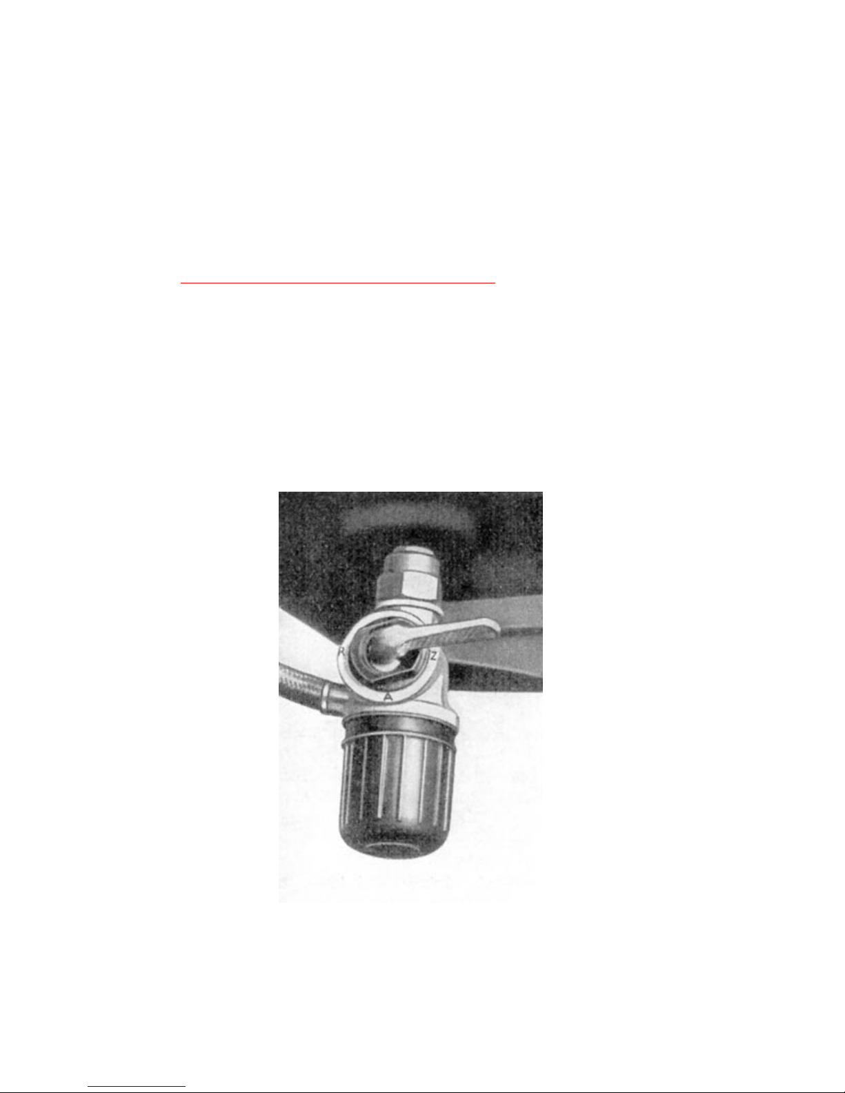
2.36 Tank
The tank has a capacity of appx. 3.1 us gallons, of which 1.32 quarts are accessible through
Image 44. Fuel tap
Fuel tap positions:
Z=closed
A=open
R=reserve
Page 49
the fuel tap´s reserve setting. The fuel tank is installed on the hood mount and affixed with a
tensioning belt. The fuel tap is installed on the left hand under side of the tank.
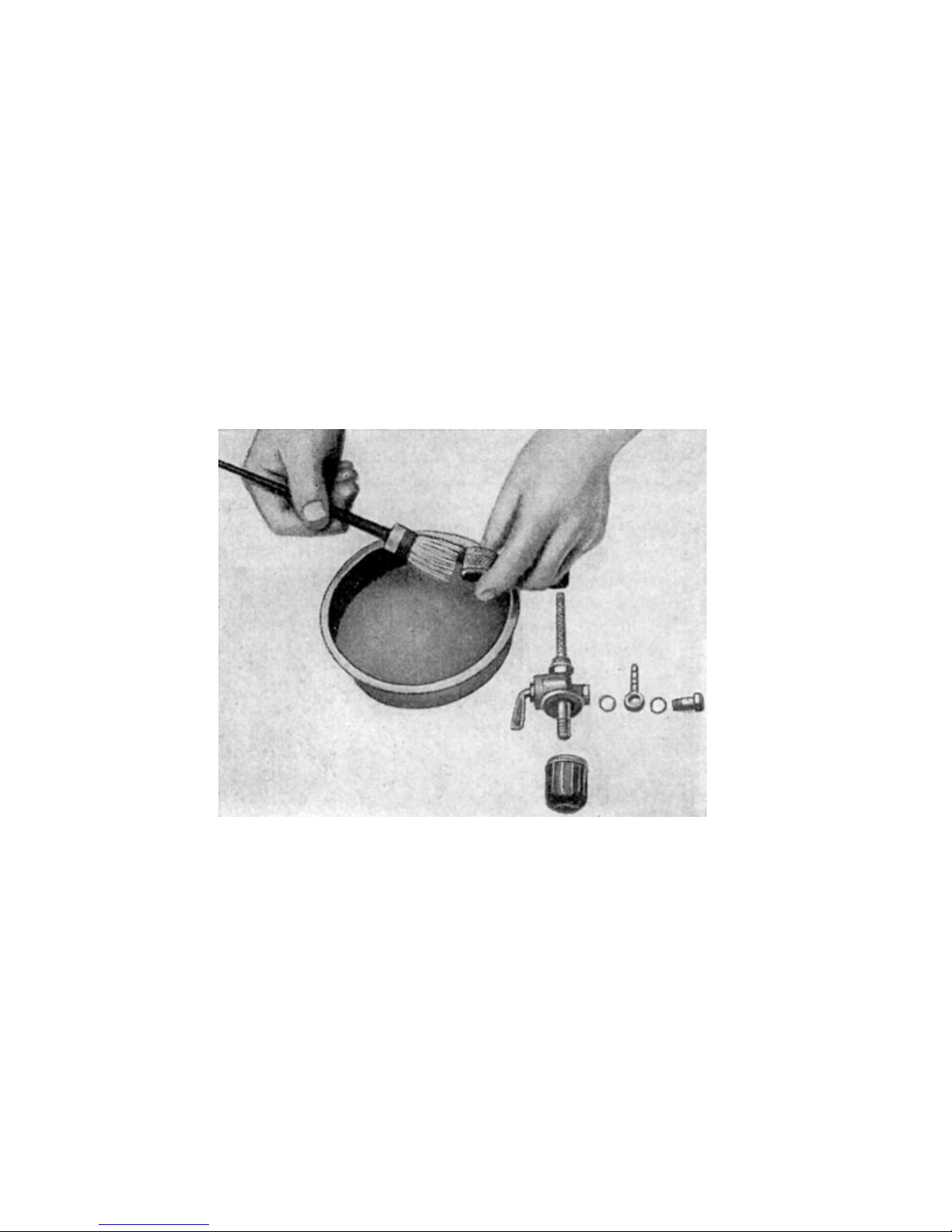
2.361 Cleansing the fuel filter
The fuel filter is part of the fuel tap.
The fuel filter filters dirt particles before they can get into the floater housing of the carburetor. To
avoid reduced flow rate, the filter should be cleased regularly.
To cleanse the filter, it needs to be removed from the fuel tap by unscrewing it. After removing the
screen from the filter housing, both parts are washed out in benzine. When reinstalling the filter into
the fuel tap, insure that the filter housing seal is in place and undamaged.
Image 45. Cleansing the fuel filter
Page 50
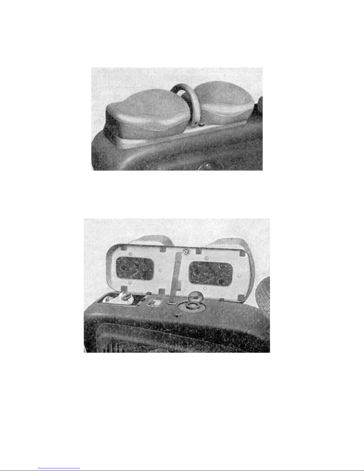
2.37 Driver and buddyseat
The coil spring cage based driver- and buddyseat are mounted on a mutual base frame and are
made from foam rubber.
Image 46. Driver- and buddyseat
Image 47. Opened base frame
The base frame is opened sideways to refuel the scooter. The opened base frame also enables
access to the tool kit, which after being removed, can be used to work on the spark plug that can be
accessed easily by opneing the little round door in the hood. A security lock prevents unauthorized
access to the toolbox.
Caution: Never clean seats with fuel, bezine or thinner.
Page 51
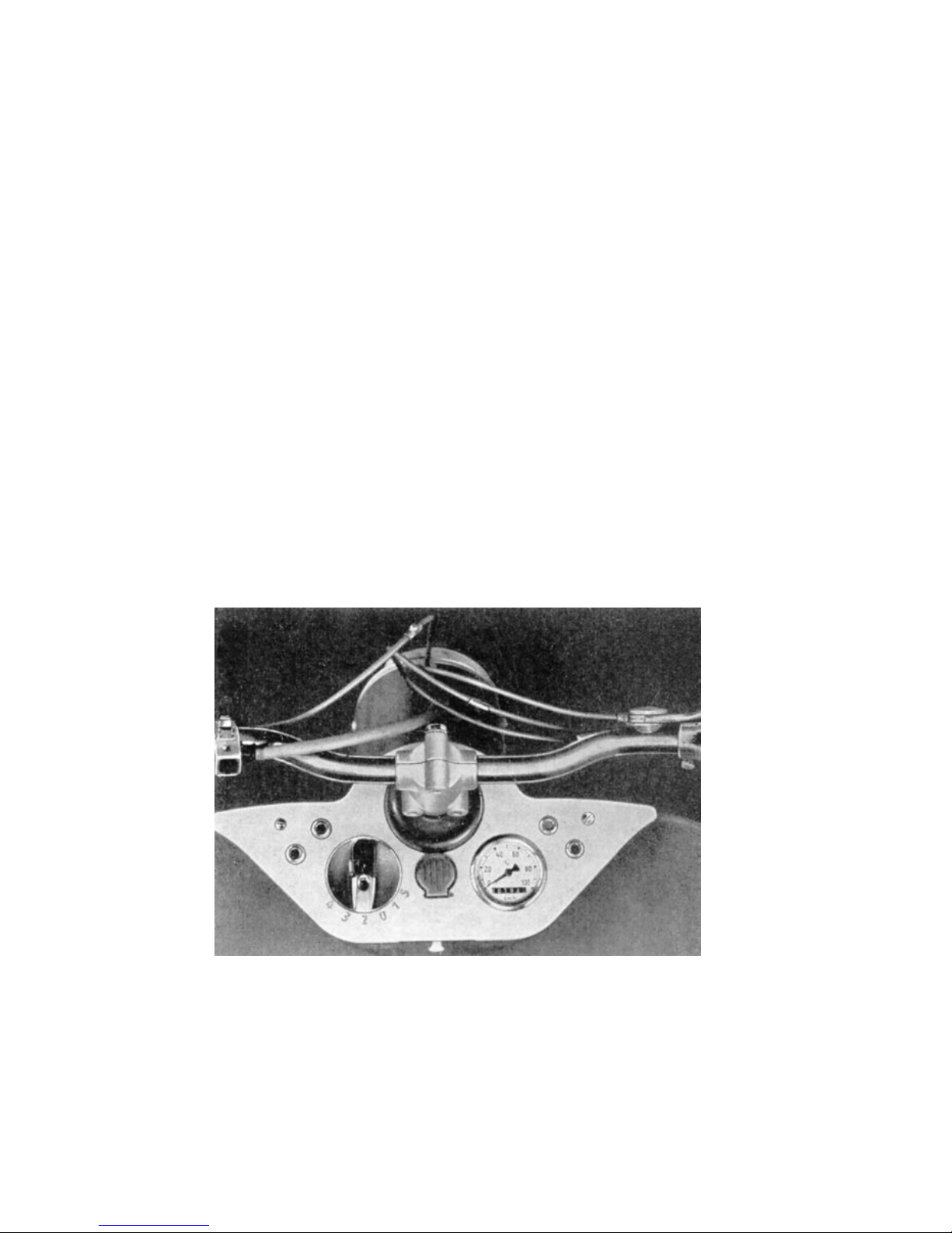
2.38 Instrumentpanel and theft protection
The necessary pilot lights for the scooter as well as the electronic switches are mounted evidently
on the instrument panel.
The following lights, switches and instruments are to be found on the instrument panel:
left hand side: red pilot light and green neutral indicator light. Right hand side: orange supercharger
pilot light and a blind light which is mounted for the purpose of symmetry. It could be connected to
serve as a hi beam indicator for example. The speedometer is mounted on the right hand side of
the instrument panel, ignition and lightswitch on the left.
The theft protection is mounted in the center of the instrument panel and equipped with a cover
plate to protect it from water.
Operating the instrument panel:
1. Open cover plate
2. Insert key (also fits for opening base frame) and turn right
3. Turn handlebar to the left until the locking pin engages noticeably
4. Once the locking pin is engaged, the key can be turned by 180º and pulled out. Now
the scooter´s handlebar is arrested.
Image 48. Instrumentpanel
Page 52
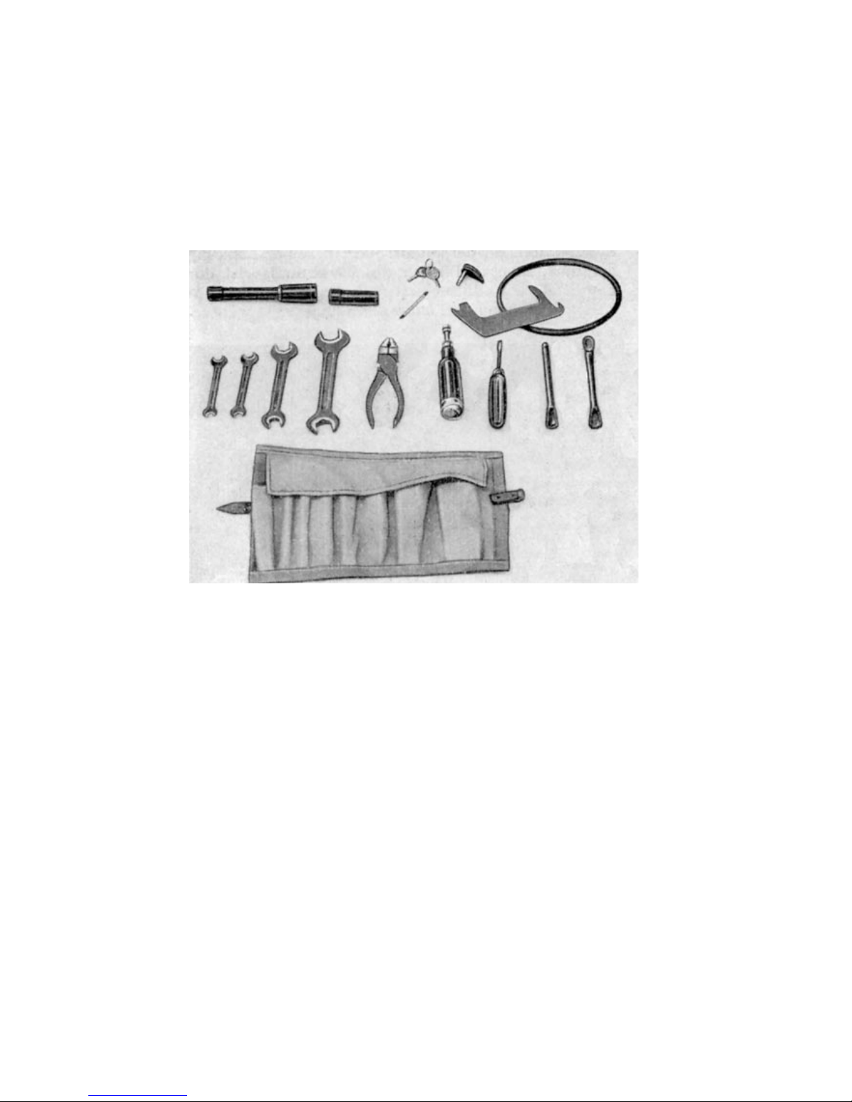
2.39 Tools
For the necessary maintenance work and little repairs incase of breakdown, which can possibly
surprise any motorcyclist once, a complete set of emergency tools is provided in the toolbox under
the base frame of the seats. This tool kit consists of the following:
Image 49. Tool kit
2 mounting levers
1 spark plug spanner
1 screwdriver
4 wrenches, sizes 8-10mm, 9-11mm, 14-17mm and 19-22mm
1 pair of universal pliers
1 grease gun
1 sensing gauge
1 extension for socket wrench (for tire exchange)
Also included in the toolkit is spare v-belt for the supercharger 8x5x475.
Page 53
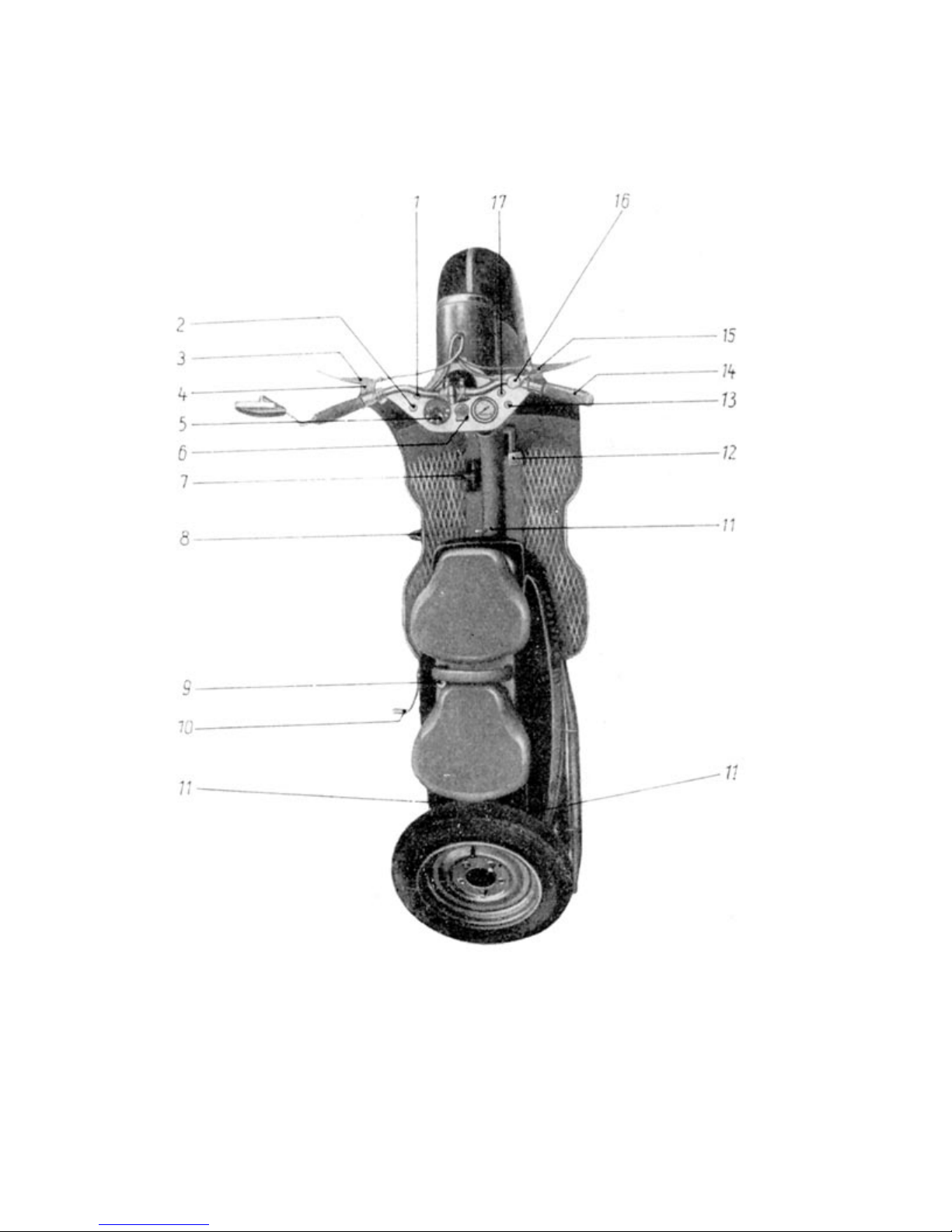
3 Operating instructions
3.1 Orientation and intention of the control elements
Image 50. Orientation of the control elements
(1) Neutral gear pilot light, (2) Charging status light, (3) Clutch lever, (4) low beam switch and signal
switch, (5) Ignition and light switch, (6) Theft protection, (7) foot gear switch , (8) Sidestand, (9)
Security lock, (10) Kickstart, (11) hood mount (12) foot brake lever (13) Supercharger pilot light (14)
Throttle (15) Hand controlled brake (16) Choke lever (17) Blind pilot light
Page 54
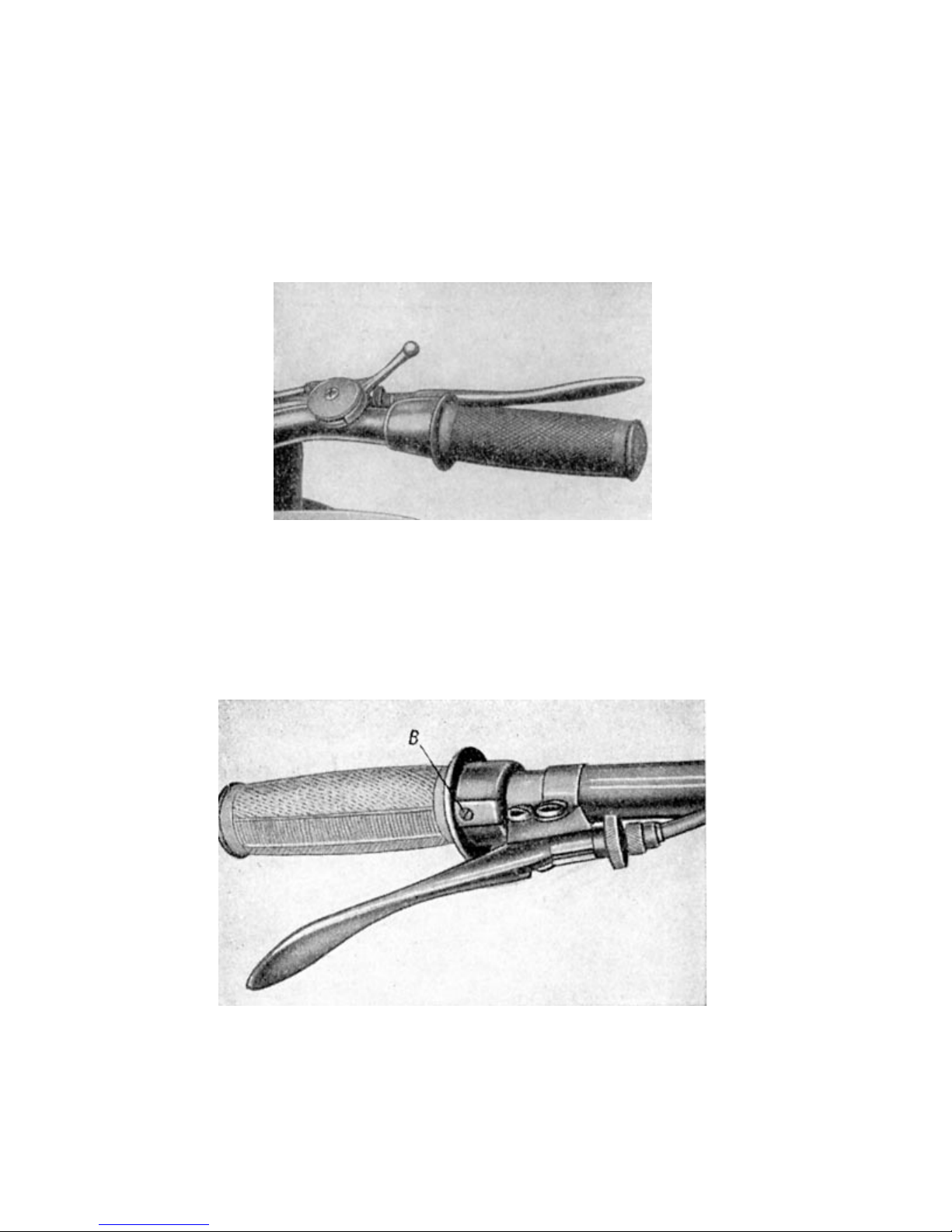
3.101 Choke lever
The choke lever is mounted on the handlebar and controls the air slide gate of the carburetor. If the
lever is pushed forward (in driving direction), it closes the carburetor´s intake manifold partially
resulting in a thicker ratio necessary for cold start.
After startup, the lever should slowly be pulled back to avoid unwanted oversaturation of the ratio. If
the engine is still warm from previous use, the choked needn´t be closed (pushed forward) because
it tends to stall the engine. Applying the dabber also stalls an already warm engine.
Image 51. Handlebar with choke
3.102 Throttle
The position of the carburetor´s round slidegate and thus the engines rpm´s are determined by the
throttle control on the right hand side of the handle bar.
Image 52. Throttle setting
(B) Adjusting screw for stoppage in the handle
An adjustment screw labled „Bremse“ (engl. Brake) is installed in the turning handle and can be
used to set the smooth running of the throttle according to the personal prefernce of the driver.
Page 55

3.103 Ignition and lightswitch
The combined ignition and lightswitch unit is found on the left hand side of the instrument panel like
already described in section 2.38. The ignition key can be pulled out in positions 0 and 1.
Relevance of the key settings:
Position 0: Ignition and lights switched off – key removable (Parking during daylight)
Position 1: Ignition switched off, parking lights (rear and front) on – key removable
(Parking at night)
Position 2: Ignition switched on, light switched off, - key not removable (For kickstarting
engine and driving during daylight)
Position 3: Ignition switched on, parking lights (rear and front) switched on – key not
removable (For city driving at night with city lights)
Position 4: Ignition switched on, head light and taillight switched on – key not removable
(For driving at night)
Position 5: Ignition switched on (however, no red pilot light), lights switched off – key not
removable. (This is the setting for push starting the scooter in 1
st
or 2nd gear
due to empty or missing battery)
When switching on the ignition, the red pilot light goes on (except when in position 5) to
acknowledge contact between the ignition coil and the battery. When the engine is being
accelerated, the red pilot light must go out. If the red pilot light does not go on when the ignition is
switched on, or if the pilot light does not go out when accelerating, it means that the equipment is
malfunctioning. An immediate search and repair of the error is necessary. (See section 4.32).
Also the green neutral gear pilot light on the left hand side of the instrument panel must light up
when the ignition is switched on. If this is not the case, disengage gear and bring it into neutral
using the foot gear switch before kickstarting the scooter. Neutral can be found inbetween 1
nd
2
gear.
st
and
When parking the scooter with parking lights on, leave the ignition on position 1. It is also
advantageous to not have the headlight on, while kickstarting the scooter to avoid unnecessary
weakening of the spark. Only turn the headlight on, when the scooter is running.
The horn is only active on ignition positions 2, 3, 4 and 5, to prevent unauthorized access when the
scooter is parked.
Page 56
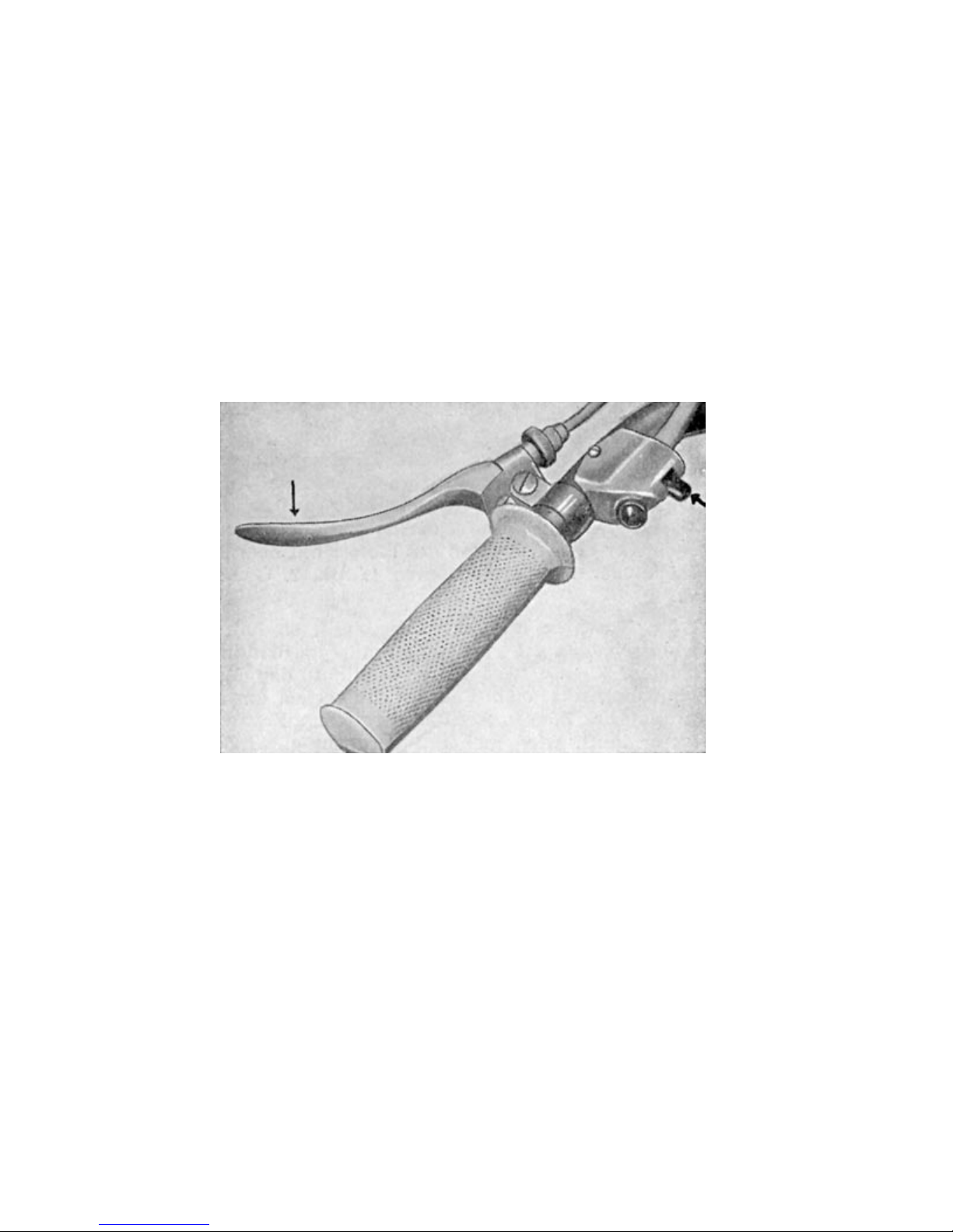
3.104 Dipswitch (Low beam switch)
Th dipswitch on the left hand side of the handlebar is mounted for convenient access by the left
hand´s thumb. It can be switched up and down to toggle between hi and low beam.
3.105 Clutch lever
The clutch lever is also found on the left hand side of the handlebar. When actuated (pulled in) the
clutch separates the power train between motor and gear box. The clutch lever must always have a
„dead gear“ of 2-3mm.
Image 54. dipswitch and clutch lever
By applying force to the lever with your hand, the transition from „dead gear“ to active gear can be
felt. Adjusting the „dead gear“ is done by either a little little pressure screw that is located at the
right hand side of the engine housing or the ring nut located at the clutch lever. (See section 2.211).
The clutch lever must never be released at once, but instead gradually and efficiently, because
otherwise engine and power train would be unecessarily strained. Also when starting up, the
scooter would propably stall.
Page 57
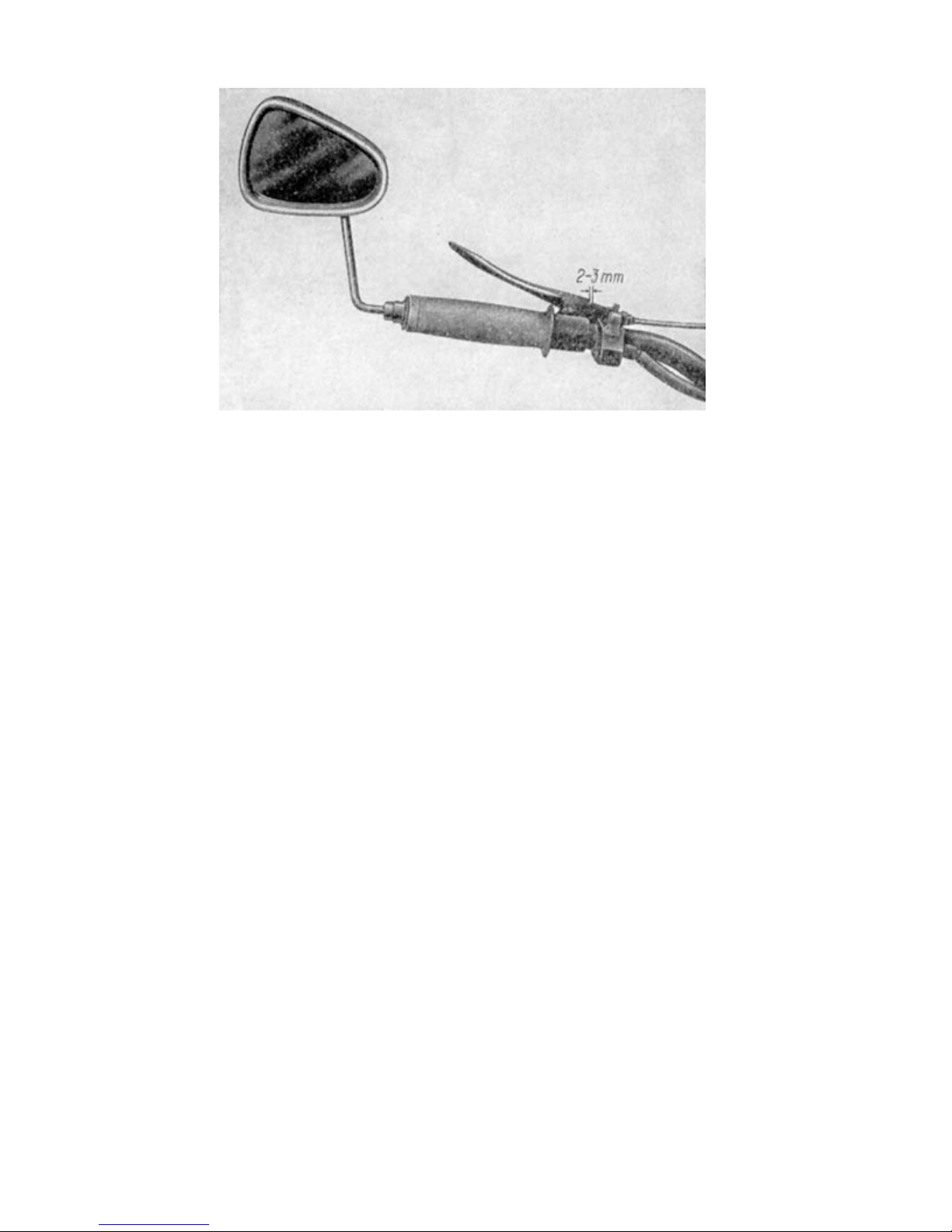
Image 55. Play of clutch lever
3.106 Kickstart
The prominent kickstart on the left hand side of the hood is provided for kickstarting the engine. If
the kickstart can´t be kicked down because the mechanism is locked in sprocket on sprocket, the
scooter needs to first be pushed back and forth a little to switch it back into neutral gear.
Page 58
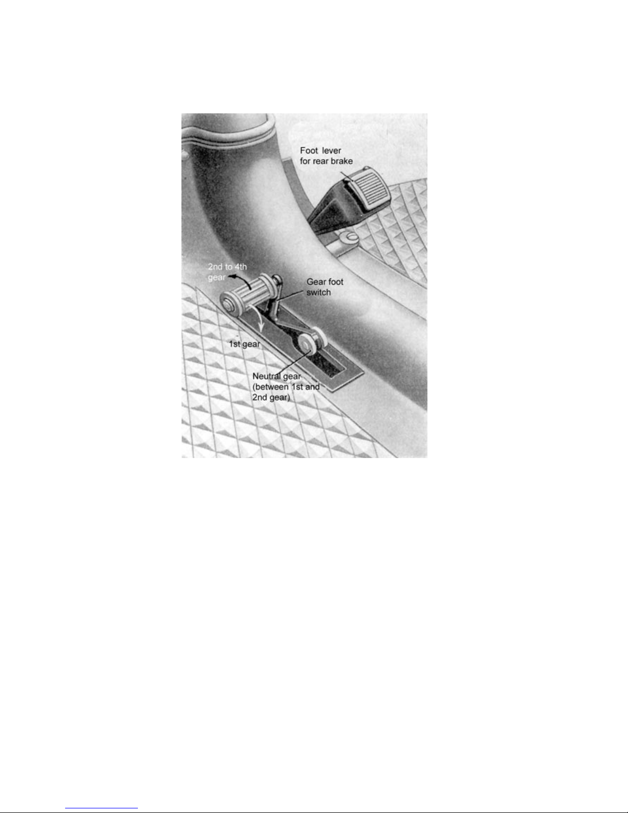
3.107 Foot gear switch
The foot gear switch is located on the left hand side of the floor board. Actuating the gear switch will
cause the switch shaft, which is beared within sleeve shaft of the kickstart to change
Image 56. Actuation of foot gear switch
the different gear ratios within the gear box. The gearbox has an automatic switch installed, that
returns the footswitch back into it´s original position after each switching operation. The foot gear
switch must be pushed forward to move the gears up into 2
down again. To switch from neutral into 1
To switch from:
Neutral to 1
st
1
gear to 2nd gear push forward
nd
2
to 3rd gear push forward
rd
3
to 4th gear push forward
th
4
to 3rd gear push back
rd
3
to 2nd gear push back
nd
2
to 1st gear push back
Neutral is found inbetween 1
st
gear push foot switch back
st
and 2nd gear. It can be located by applying slight pressure to the foot
switch (push back when coming down from 2
st
gear, the switch must also be pushed back.
nd
gear and push forward when coming from 1st gear).
nd
,3rd and 4th gear and down to switch
When neutral is found, the green pilot light on the left hand side of the instrument panel will also
light up.
Page 59
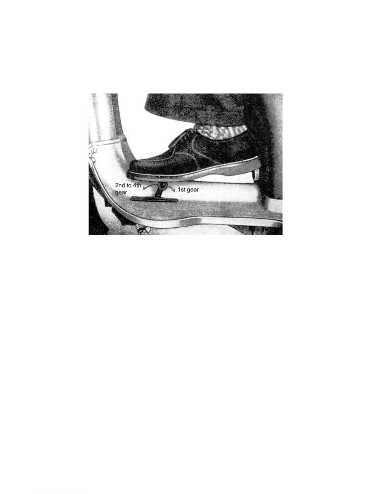
3.108 Rear brake foot lever
The rear brake foot lever is found on the right hand side of the floor board. Pushing it down will
result in actuating the rear brake. The rear brake can be adjusted by using the adjustment screw at
the rear end of the break cable.
Image 57. Foot gear switch and rear brake foot lever
(1) Foot gear switch
(2) Rear brake foot lever
3.109 Front brake lever
The lever provided on the right hand side of the handle bar activates the front brake. It should be
used to support the rear brake, when slowing down. In conjunction with the rear brake, the front
brake is especially valuable on longer downhill rides due to the relocation of the center of gravity.
Using the front brake only occasionally bears the danger, that it will not function as well as it should
when it´s needed for emergency situations for instance.
Page 60
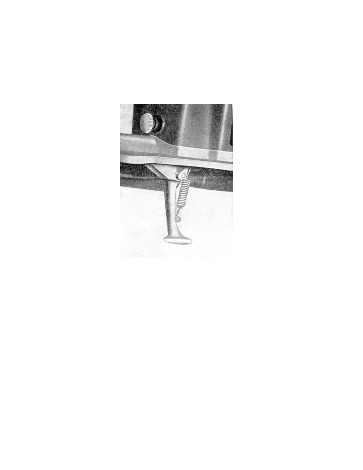
3.110 Sidestand
The sidestand is found on the left hand side of the floor panel. It is used to park the vehicle. By
slightly tilting the scooter into the opposite direction, the sidestand can be accessed easily.
CAUTION: Before sitting on the scooter the sidestand has to be retracted. Otherwise the floorboard
may be damaged.
Image 58. Sidestand
3.111 Tip up hook
A tip up hook can be found on the instrument panel´s housing and used for convenience purposes
like hanging up a purse or a brief case while on then road. Pushing down the button, opens the
hook for use.
Page 61

3.2 Proper operation
3.21 Before your first ride
The following things need to be done, before starting the engine for the first time:
1. Check battery for correct charge. This can be done by turning the headlight on and
honking the horn. (The first time charge of the battery should be done by an IFA
customer care center.)
2. Fill the fuel tank with fuel (ratio of 5% oil). Only use mineral oil for mixing if possible !
Mixing oil with fuel is done in a container outside of the fuel tank, to insure proper
blending of oil and fuel. Never try blending oil and fuel in the tank, relying on the oil to mix
itself with the fuel.
We strongly recommend the new 2-stroke oil „Hyzet 43 Mot. SM“ for use with the
SR59 Berlin scooter. It runs smoother but the ratio stays at 5%.
3. Check transmission fluid level
4. Check tire pressure
Tires must be checked for correct tire pressure on a regular basis.
The correct tire pressure for the SR59 Berlin is:
Single driver: front 17.6 psi
rear 22.0 psi
Driver & buddyfront 22.0 psi
rear 29.4 psi
The pressures should not fall bellow the the suggested rates, because it might lead
to unsound tires.
5. Check for function of front and rear lights as well as function of the pilot lights on thje
instrument panel.
6. Check braking action of front and rear wheel (See section 2.34).
3.22 Running in
All movable parts of a new scooter must be run in. Especially Power trains and and engine must be
run in although they were manufactured to highest technical standards. This makes it important to
not overstress the engine throughout the first 900miles.
The driver and owner of a new motorscooter must know that the durability and reliability of the
scooter will be better, the more diligence is applied especially during the running in period of the
scooter. For this purpose, the following speed suggestions should not be exceeded while running
in the scooter:
st
1
gear appx. 9mph
nd
2
gear appx. 18mph
rd
3
gear appx. 28mph
th
4
gear appx. 37.5mph
As much as excessive speeds are to be avoided, driving too slow also damages the power train
and the engine while driving in the scooter. In result it should be taken great care, to switch gears in
Page 62

the appropriate moment on the way up to 4th as well as down again. Don´t accelerate to the highest
possible speed in each gear after the 900miles of running in are up. Only after 1800 miles are all
parts ready to be strained without running into the danger of being damaged.
3.23 Starting up
To start the cold angine, folle these steps:
1. Position the gears into neutral, by using the foot gear switch (Green pilot light lights
up when in neutral).
2. Open the round door on the hood and switch the fuel tap lever to „A“, open (lever
pointing down). Also see image 44 in section 2.36 for details.
3. Push down carburetor´s dabber until fuel overflows (appx. four to seven seconds)
4. Close choke (Also see section 3.101) and close round hood door.
5. Open thottle by about ¼ to ½ .
6. Efficiently kickstart the engine twice.
7. Switch ignition to position 2 (Charging light, Supercharger pilot light and Neutral gear
light light up)
8. Start engine by powerful kickstart.
9. Open choke slowly
10. Close throttle almost fully and keep engine idleing.
Once the engine is running, the red and orange pilot light should extinguish (If they don´t, see
sections 4.32 and 4.33). The green neutral light will first go out, when a gear is engaged. If these
lights fail to light up with the ignition switched on, the battery is most liekely empty. With the battery
removed from the scooter, it can still be started by setting the ignition to position 5 and push starting
the scooter with 1
st
or 2nd gear engaged. If one of these lights fails to light up with activated ignition,
one of the systems is propably malfunctioning (See section 4.31 accordingly).
3.24 Running up and shiffting gears
Running the scooter up is done as follows:
1. Engage clutch by pulling clutch lever.
2. Push foot gear switch back (engages 1
3. Release the clutch efficiently and at the same time accelerate the thottle.
(Motoscooter starts to moving)
st
gear and green pilot light goes out)
4. After about 6 yards or reaching a speed of about 9mph, pull clutch lever and reduce
throttle. Now push foot gear switch all the way forward, until it reaches limit stop.
(switching into 2
nd
throttle.
gear) Release clutch efficiently and at the same time accelerate
Page 63

5. A soon as a speed of 18mph is reached, follow step 4. to switch into third gear.
6. Repeat step 4. for switching into 4
th
gear as soon as a speed of about 37.5mph is
reached.
3.25 Shifting down on a slope
If the motor doesn´t seem to make an ascending slope with the current gear engaged and the
speed goes under the recommended amount, it is necessary to downshift accordingly.
Therefore:
1. Engage clutch and reduce throttle by about ½ .
2. Push foot gear switch back (engage next lower gear)
3. Disengage clutch and accelerate throttle.
This description needs to be followed in a speedy and efficient fashion, so that the speed of the
scooter doesn´t drop too fast.
If the motor doesn´t make the slope with one gear already shifted down, or if the speed get´s below
specifications in city traffic, repeat steps 1. through 3. accordingly.
CAUTION !!
It is not adavantageous to use the engine break with a 2-stroke engine. A two-stroke engine should
always be kept on revolutions. The engine will work more efficient and, although in higher
revolutions, the engine won´t be strained as much as if it were used with the engine break.
A lot of drivers tend to go downhill in top gear and have the throttle closed in the same time. We
would like to remind you, that even in driving school it is advised to use the same gear uphill as you
should going downhill. This is extremely important with a two-stroke engine, because the engine is
lubricated by the fuel. When you are using the engine break, (high gear with closed throttle) you are
denying the engine it´s lubricant and thus run into the risk of severely damaging your engine (piston
seizure or serious damage of the bearings might occur as a result of that). So always make sure,
that the engine is supplied with some fuel (open throttle to an extent.
3.26 Brakes
regulation of the scooter´s speed should be possibly be maintained by the throttle. The brakes are
sufficient to bring the scooter to a safe halt coming from any speed. Braking is usually conducted by
first using the foot brake and then gradually adding the front brake as a support to the rear brake.
Even when sudden obstacles appear in the way, that require sudden heavy braking, the brakes
should not jam. The brake performance of a jammed wheel is not as good as if the wheel were just
heavily decelerated. Also never use the „engine break“ with a two-stroke engine (See section 3.25).
3.27 Stopping
Follow these guidlines to bring the scooter to a full stop:
1. Close throttle
2. Engage clutch, accelerate throttle for a short moment (open throttle and close it
again) and maneuver the gear box into neutral gear using the foot gear switch (green
pilot light on the instrument panel will light up) and disengage the clutch.
Page 64

3. Bring the scooter to a full stop by applying the brakes
Incase the scooter should be parked:
4. Turn off ignition
5. Close fuel tap.
3.28 Mothballing the bike for storage
If the scooter should be mothballed during winter or for any other reason, the following things apply:
1. Jack up the scooter by placing logs under traverses and underbody (three point
storage) and clean scooter thoroughly.
2. Empty fuel tank and carburetor.
3. Lube all lube points (see supplied lube chart for reference)
4. Reduce air pressure in all tires to appx. 8Psi. At this point ensure, that the scooter is
jacked up properly so that the tires are disencumbered
5. Remove battery and have it serviced at a professional battery shop.
.
6. Spray body with paint protection and coat blank parts with vaseline.
7. Cover scooter with canvas to protect it against dust.
4 Protection and maintenance work
4.1 General information
The supplied maintenance booklet gives information on when the scooter should be inspected by
an authorized dealer and what should be taken care of at which mileage (The speed´s mileage
counter is used as reference).
Non observance of the maintenance booklet results in loss of possible warranty.
We do however want to point out, that additional care can´t hurt.
When lubing the scooter, never forget the front and rear suspension, especially when driving a lot
on bad roads or through wet conditions.
So spare no effort or dirty hands for the little trouble. Your scooter will certainly appreciate it !!
4.2 What to do
4.21 Daily
4.211 Before leaving the driveway
1. Check tank for sufficient fuel
2. Check functionality of lights and horn
Page 65

3. Check for sufficient play on the clutch (two to three millimeters). (Also see image
55).
4. Check air pressure. (See section 3.21)
5. Check brakes
4.212 During stays in transit
1. During short stops after a longer drive, it is advisable to check the tire temparature.
Unusually warm tires leave to conclude, that the air pressure is too low (great
thermal stress caused by excessive friction).
2. Check tires for nails or other objects that might stick in the tires, especially after
driving on dirt roads or low quality streets.
4.213 After returning
1. Check tires as described in section 4.211
2. After long drives over dirty or sandy roads, (summertime), clean air filter and
coat it with oil (Also see section 2.182).
3. After driving in bad weather: spray scooter off with water while the dirt is still moist.
4. Close fuel tap after parking the scooter.
4.22 Lubricating the engine
This engine works with an oil-fuel ration of 5%. This means, that the engine is lubricated by the oil
additive in the fuel. Never fill scooter up with unmixed fuel !! Operating the engine without oil
additive, would destroy the crank, big end bearings and the cylinder track, because they would run
dry. To ensure proper lubrication of the engine at all times (winter or summer) therefore is 5%.
4.23 Lubricating the chassis
Lubrication of the chassis at the lube nipples (see lube chart for details) is just as important as the
lubrication of the engine and gear box. Lubrication is applied with the supplied grease gun. With
exception of the cable nipples, every nipple is lubed with grease. The cables are to be lubed with
thick engine oil (NO grease !!).
The joints of the handlebar levers are lubed with a few drops of motor oil.
Malfunction of the grease gun:
Incase of contamination of the lubricant inside the grease gun, which may cause the grease gun do
not operate, remove the mouthpiece and take out the valve spring with ball. Afterwards clean parts
from contaminated lubricant and reassemble grease gun.
Page 66

Lube chart
No. Lube point No. Of Lubricant
Lube points
1 Front fork (under fender) 2 Grease
2 Brake lever, front 1 Grease
3 Speedometer 1 Grease
4 Spring retainer 2 Grease
5 Rocker bolt 2 Grease
6 Foot brake lever 1 Grease
7 Clutch spring 1 Grease
8 Rear wheel rocker arm 2 Grease
9 Foot brake cable 1 Motoroil
10 Chainlubrication 1 Motoroil
11 Gear box filling screw 1 Motoroil
12 Inspection screw for gear box 1 Motoroil
13 Kickstarter 1 Grease
14 Foot gear switch 1 Grease
15 Engine lubricant Mixture Fuel-Oil 5%
The Bowden cables do not carry lube points anymore, due to more advanced methods of production. They are
bathed in graphite before assembly. Just disassemble every 3000 miles and oil as described in section 4.23
Supercharger: Both Ballbearings are factory assembled with hotgrease. This lasts for appx. 21000
miles.
Page 67
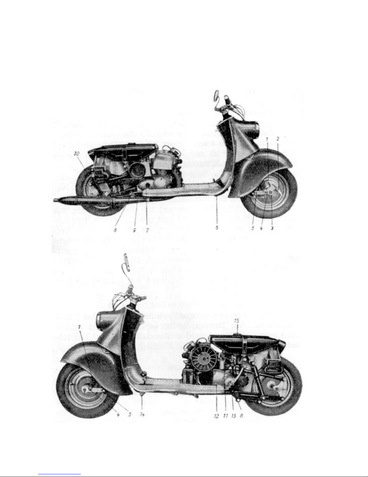
Page 68
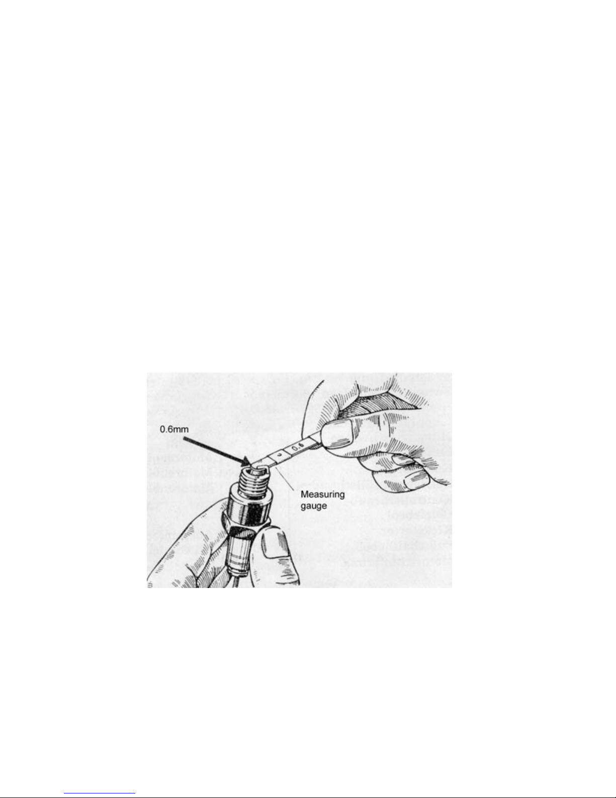
4.24 Maintenance of spark plug
The state of the spark plug changes during operation as a consequence to the high mechanical,
chemical and thermal strain it is exposed to – it ages. Regular maintenance and check up´s of the
spark plug´s aging process is necessary in order to keep the engine reliable and safe.
For the beginning, it is important that the inner parts of the spark plug are clean. To maintain this,
the spark plug should be removed every 600 miles and cleaned using a wire brush (Do not burn the
spark plug out and don´t use any so called „spark plug cleaners“!). Also important is the right
distance of the electrodes. Isolator spark plugs hav a distance of 0.6mm. Since this distance grows
due to electrode burn up, the outer electrode needs to be bent in until it´s back to it´s original
distance of 0.6mm. This can either be done by using the supplied sensing gauge (see image 61.) or
by simply stacking 3 postcards on top of eachother and using them to measure the distance. The
appearance of the spark plug´s inner parts, the so called „face“ concludes the burn-up of the engine
and so gives the opportunity, to detect disturbances in the engine´s combustion processs timely
and thus enables early troubleshooting (See section 4.241).
When reinstalling the spark plug, do not forget to also reinstall the spark plug gasket.
After about 6000 miles the spark plug has aged so far, that it can´t bear up against the thermal
forces within the cylinder. To prevent possible damages to the engine, the spark plug has to be
exchanged about every 6000 miles.
The right spark plug for the engine of the city scooter „SR59 Berlin“ must have a heat-count of 240.
Never should spark plugs be used, that have a lower heat-count, because it might cause severe
damage to the engine. Spark plugs with a higher heat-count are unnecessary and will cause
complications.
Image 60. Sparkplug maintenance
Page 69

4.241 What does the spark plug´s face tell us ?
If the right sparkplug´s inner parts (the „face“) are black (meaning oily or grimy) one of the following
problems could be responsible:
a) Distance of spark plug´s electrodes is too small
b) carburetor ratio is too thick
c) Mechanical defects of the carburetor that lead to an over enriched ratio like a worn
out floater needle or a defective floater.
d) Dirty air filter
e) Too much oil or the wrong kind of oil in the fuel mix
f) Wrong ignition timing
g) Mechanical defects in the Ignition (dirty or stuck breaker lever, wrong points
adjustment or condenser or ignition coil defective).
h) Significant build up of fuel residue within the engine compartment (burned in piston
rings or dirty ports and exhaust).
i) Vehicle is being operated too slow
If the right sparkplug´s face is light colored (white-grey) and the electrodes show signs of little pearl
like objects, the sparkplug was overheating. The following problems might be responsible:
a) Electrode distance too big.
b) carburetor ratio is too lean.
c) Mechanical defects of the carburetor that result in a ratio, that is too lean like fuel
level in the floater chamber is too low, carburetor is slant or loose or the carburetor´s
mixing chamber tightning nut is loose.
d) Obstructed fuel supply (Fuel filter dirty, fuel line clogged or dirty carburetor).
e) Defective engine gasket.
f) Missing air filter.
g) Not enough oil or oil of poor quality in the fuel mix.
h) Wrong ignition timing.
i) Sparkplug old or missing sparkplug gasket.
Page 70
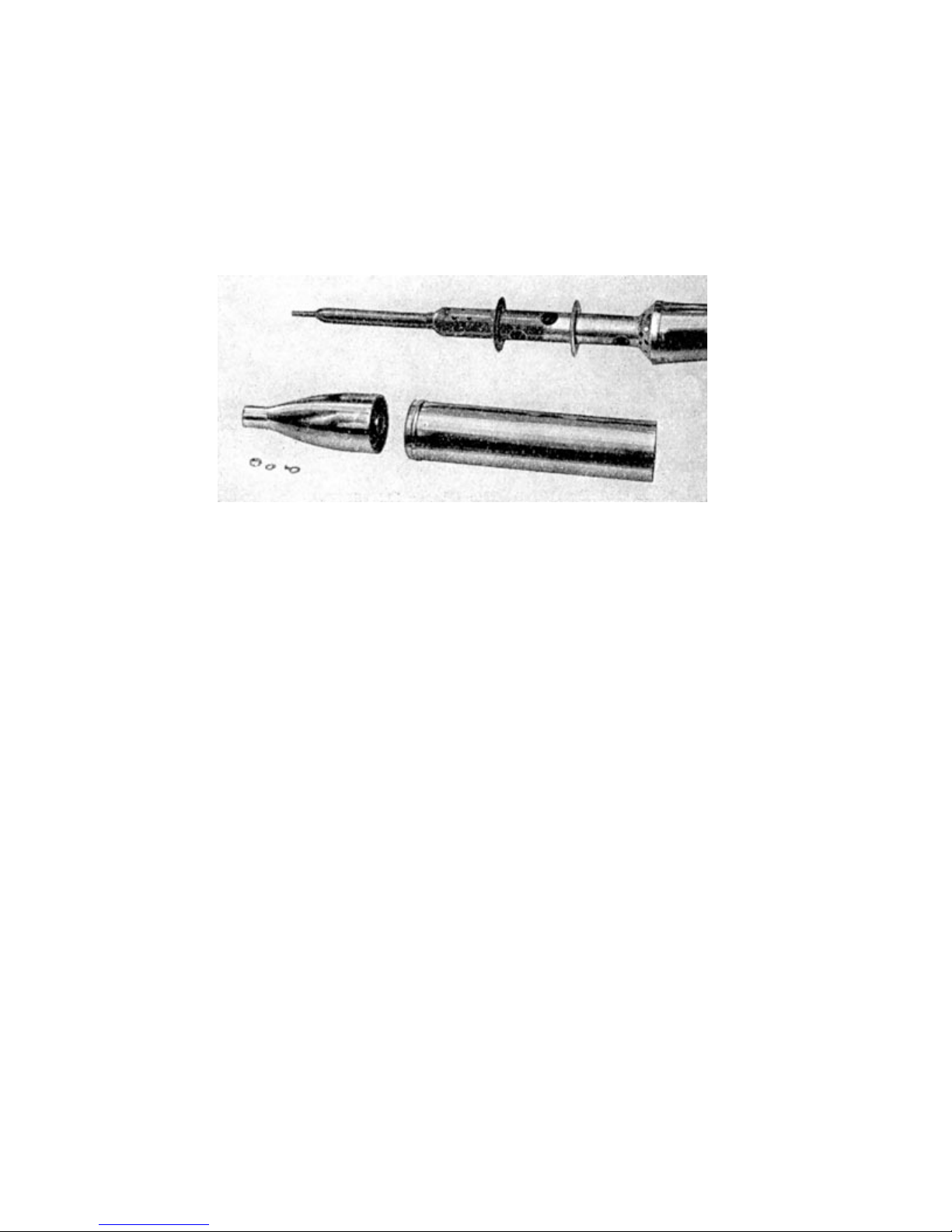
4.25 Cleansing the exhaust
The exhaust fumes are conveyed through the exhaust into the open. The exhaust collects all kinds
of residue that, depending on operation mode and used fuels, need to be cleaned out after about
3000 miles. If ignored, the residues result in lacking performance and higher fuel consuption. The
exhaust of the SR59 Berlin is demountable. After removing the nut, which is connected to the end
of the exhaust, the end piece and the blind can easily be removed.
Image 62. Dismantled exhaust
Page 71

4.3 Troubleshooting
4.31 Engine won´t start
No fuel overflowing while pushing down the dabber. This can have the following reasons:
a) No fuel in the tank
b) Fuel tap closed or not on reserve.
c) Dirty fuel filter.
d) Airhole in fuel tank lid clogged (The air hole is not visible from the outside).
e) Clogged fuel line.
Fuel does overflow while pushing down the dabber, but the engine still won´t start:
a) Clogged jet.
b) Throttle or choke are not in the according recommended positions for engine start
(warm or cold motor).
c) Ignition is switched off.
Ignition is switched on but the red pilot light won´t go on.
a) Defective pilot light.
b) Discharged or insufficiently charged battery.
c) Bad contact within the ignition lock or the connecting cables.
d) Broken wires.
Red pilot light is on but there is no spark.
Simple inspection:
remove the sparkplug connector from the cable and hold it three to four millimeters close to the
cylinder. When kickstarting, a spark should jump over. If no spark should occur even after repeating
this procedure, one of the following problems might be responsible:
a) breaker lever doesn´t lift off.
b) Burned points.
c) Stuck breaker lever.
d) Connectors to the ignition coil have bad contact.
e) Ignition cable, condenser or resistor within the sparkplug connector defective.
f) Broken wire.
Page 72

There is spark throughout the advised inspection but the engine won´t start:
a) Electrode distance too large or too small, due to the different atmospheric pressures
within the combustion chamber. (More precise inspection of the sparkplug in a dry
well).
b) Sparkplug oily or broken.
c) Engine flooded due to excessive dabber use.
d) Too much oil in the ratio.
e) Sparkplug connector defective.
4.32 Red pilot light does not go out after
starting the engine
a) Defective reverse current switch or bad ground.
b) Loose contact at the cable connectors.
c) Defective regulator
d) Defective alternator due to dirty commutator, hanging brushes or short circuit within
the coil.
4.33 Supercharger pilot light doesn´t go out or lights up while
driving
a) Slipping v-belt fails to drive supercharger fly wheel.
b) Dodgy v-belt. (see section 2.162 for details)
4.34 Engine doesn´t run smooth
Four stroke motion (Regular failing of the ignition):
a) Closed choke
b) Dirty air filter
c) Crippled floater needle
d) Wrong carburetor adjustment, main jet too large, jetneedle too high.
e) Defective floater
f) Too much oil in the fuel.
g) False ignition timing
h) Excessive residue in the ports or in the exhaust
Page 73

Carburetor „beat´s back“
a) Obstructed fuel flow or dirty fuel filter, clogged fuel lines or dirty carburetor bores.
b) Slanting carburetor.
c) Loose carburetor.
d) Carburetor´s tightening screws loose.
e) Defective engine gasket.
f) Missing air filter
g) Wrong carburetor setting, jet needle too low or fell into needle jet entirely due to
broken clamping yoke.
h) Wrong ignition timing.
i) Old or defctive sparkplug, wrong electrode distance.
k) Breaker lever hangs or lifts off too far.
l) Points burned
m) Piston rings burned into the grooves (bad compression).
4.35 Engine stalls abruptly
a) Empty gas tank (Noticeble „stuttering“ of the engine prior to stalling).
b) Clogged tank, fuel lines or dirty carburetor.
c) Ignition cable loose or detached.
d) Defective sparkplug.
e) Broken breaker lever or fallen off contact material.
f) Defective condensor.
Page 74

4.36 Excessive fuel consumption
As with all vehicles, the specifications on the fuel consumption are standard values. Of course the
consumption changes when the engine and/or other parts of the vehicle are faulty. A higher fuel
consumption can also have one of the following reasons: higher top speeds, permanent maximum
load, off center load, bad roads and rough climate. If the fuel consumption is higher even under
normal conditions, make sure that the following conditions are met:
a) Carburetor setting, immaculate carburetor condition, clear fuel lines, clean air filter
b) Immaculate sealing of the engine.
c) Use of the right fuel mixture.
d) Correct ignition timing and immaculate condition of the mechanical parts of the
ignition.
e) Correct handling of throttle, gear switch and choke.
f) Immaculate condition of all other parts of the scooter (gear box, brakes, wheels, tires
and frame).
If the fuel consuption still seems to high, it is strongly recommended, to stop by an authorized
workshop and have them perform a test drive with the scooter so that they can determine, whether
the it is the conditions or malfunctioning of the scooter that is responsible for the high fuel
cnsumption. If the scooter is malfunctioning, the authorized dealer will gladly take care of the
necessary repairs for you.
4.37 Headlight doesn´t work
a) Light bulb loose or broken
b) Cables within the headlight have bad contact.
c) Contact faces of the springs inside the headlight are oxidized.
d) Faulty battery.
e) Broken cable.
Page 75
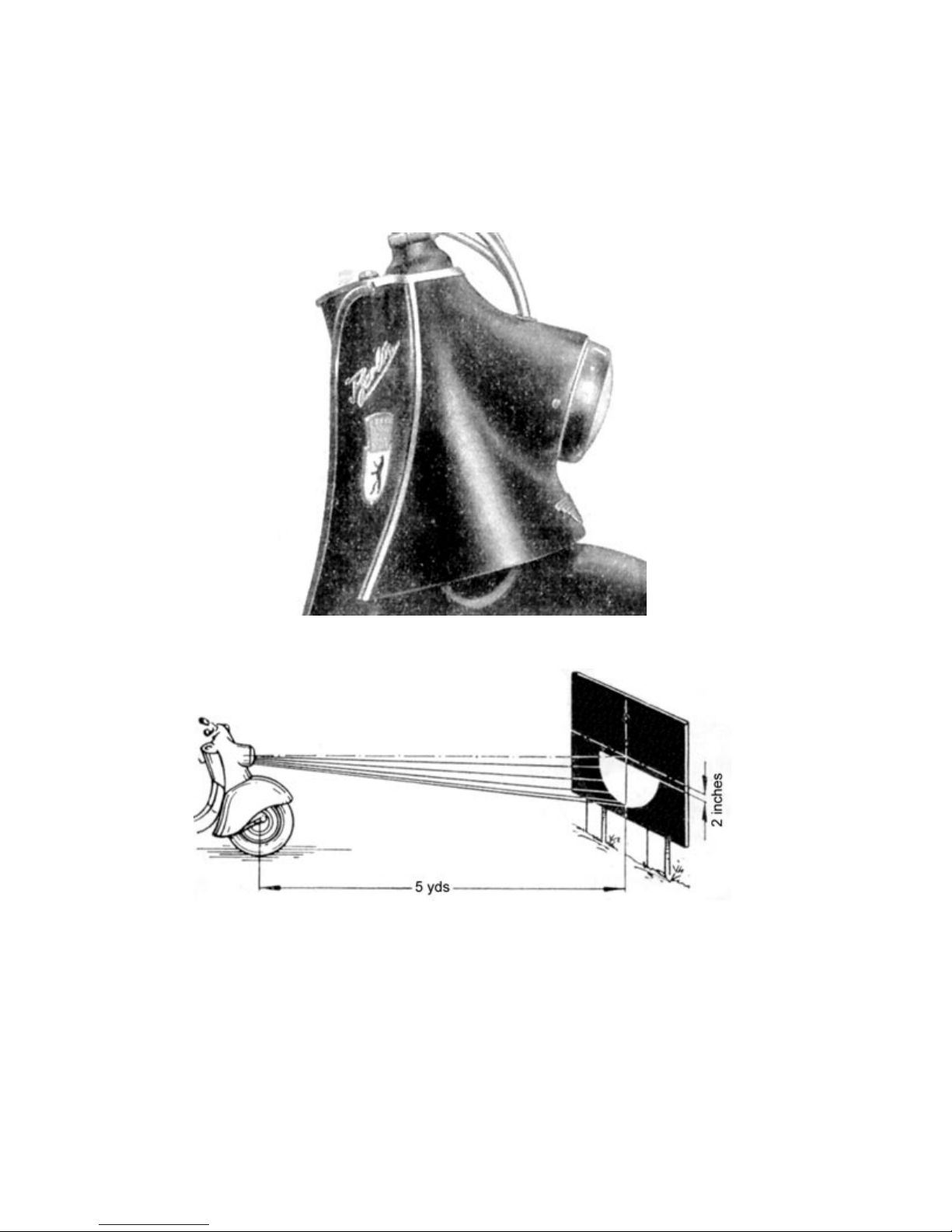
4.38 Adjusting the headlight
The following procedure should be attended in order to adjust the headlight:
a) Position the scooter perpendicular to and about five yards away from a white wall.
Image 63. Headlight bezel
Image 64. Adjustment of headlight
b) Have one or two people sit on the scooter.
c) Loosen bezel screws and adjust headlight, where the boarderline between the bright
bottom and dark upper area should be at least two inches under the center of the
headlight.
d) Tighten bezel screws.
Page 76

5 Repair instructions
5.1 Egine removal and instalation
1. Remove hood.
2. Loosen exhaust´s bolt and nut (located at right traverse) located at the bracket.
3. The tank can be removed, after loosening the carburetor´s tension belt and fuel line
as well as the dabber bracket.
4. Remove carburetor´s slidegate cap and pull cables and slidegate out of carburetor.
5. Remove ignition coil and regulatorfrom blower housing without disconnecting cable
connectors.
6. Remove Ground cable from battery and cable connector for neutral gear pilot light.
7. Loosen tightening screws from right cap and remove air intake damper.
8. Press chain protectors out of housing and open master link.
9. Loosen the three engine fixation screws that connect the engine to the frame.
10. Loosen connectores of the triple cored cable at the alternator´s cap (Mark connector
ends and bend open cable fastener under the engine open).
11. Remove battery
12. Remove foot gear switch linkage from gear box lever.
13. Pull engine out upwards first and then take it out of the frame sideways.
14. Re-install correspondingly in reverse order.
5.2 Removal of cylinder head
1. Remove ignition cable.
2. Remove the four retainer screws from the stud bolts of the cylinder (Look out for
circlips and washers).
3. Remove cylinder head.
4. Re-install correspondingly in reverse order after first cleaning the combustion area
and the sealing surfaces of cylnder and cylinder head. Don´t forget the circlips and
washers !! Tighten bolts „cross over“ and retighten some more, once the engine has
warmed up after startup.
Page 77

5.3 Removal of cylinder
1. Remove fuel tank.
2. Loosen exhaust´s bolt and nut (located at right traverse) located at the bracket and
remove exhaust.
3. Remove cylinder head as described in 5.2.
4. Loosen clamping screw at the carburetor connector and remove carburetor from
intake socket.
5. Pull cylinder out upwards (Neck of cylinder should be waggled out of dowel pin).
Mind the gasket !
6. Use a clean cloth to cover up the crank case.
5.4 Removing the piston
1. Remove cylinder as described in 5.3.
2. Remove circlips from piston pin (make sure, that the circlips don´t spring off !)
3. Incase the piston pin is stuck in the piston, carefully heat up the piston (using a
bunsen burner for example).
4. When the heat starts expanding towards the bottom end of the piston pin, press pin
out with a spike.
5. Never hammer the piston pin out of the piston !!
5.5 Inspecting or exchanging piston rings
1. Remove cylinder as described in 5.3.
2. If the piston pin is still stuck in the piston, the necessary work can be done without
removing the piston.
3. Remove piston rings using a pair of piston ring pliers or three narrow pieces of tin, to
avoid breaking or overexpanding the rings. Mark the rings in such a way, that they
can later be reinstalled in the same position in the same groove !!
4. Cleanse the piston rings and the grooves from any coal or residue. CAUTION !! do
not damage rings with inappropriate tools !!
5. Insert the piston rings into the bore one by one with the help of a cylindric shaped
piece of wood or an old piston. Push piston rings down into the bore by about half a
stroke length.
6. Now check the piston rings gap using a measuring gauge. If the gap exceeds
0.5mm, the rings need to be exchanged.
7. Reinsert rings into piston grooves, using the tools and measures described for
removal. Do not lubricate rings !!
Page 78
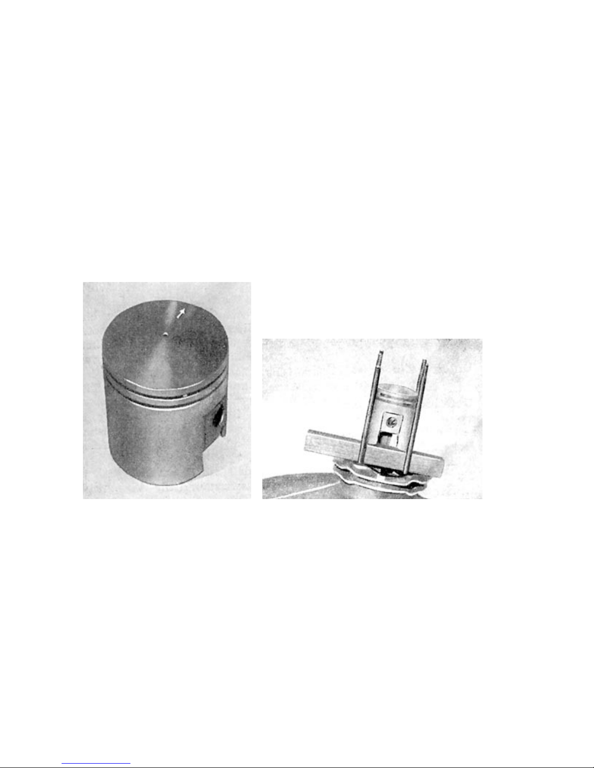
5.6 Installing piston and cylinder
1. Lubricate rod head bushing.
2. Warm up piston to about 90ºFon a cooker.
3. Put the warm piston over the rod head in such a way, that the imprinted arrow in the
piston is pointing forward.
4. Quickly push the cold piston pin through piston and connecting rod.
5. Reinstall circlips. Carefully verify the circlip´s correct seating. Lapsing circlips will
destroy piston and cylinder !!
6. Apply bottom cylinder gasket.
7. Underlay crank case flange with a piece of wood so that the piston can rest.
8. Lubricate bore (not the piston !!)
Image 65. Piston (arrow must point Image 66. Installing the piston
forward during installation!!)
9. Slide cylinder onto stud bolts.
10. Press upper piston ring together firmly using your fingers, so that the ring ends are
adjacent to the locking pin. Now slide cylinder over the piston and over the first
piston ring.
11. Press lower piston ring together firmly using your fingers , so that the ring ends are
adjacent to the locking pin.
12. Now slide the cylinder over the piston entirely. Remove underlying wood (Caution,
do not damage gasket !!) Slide neck of cylinder into crankcase.
13. Cleanse sealing surface for cylinder head.
14. Attach cylinder head.
Page 79

15. Put on circlips and washers and screw nuts on. Caution: tighten nuts cross-over !!
16. Install carburetor, fuel lines, exhaust and ignition cable.
5.7 Adjusting the ignition
1. Open breaker cap, incase the right side housing cover has not been removeed.
2. Cleanse breaker points and set the contact distance to 0.4mm at the highest possible
position of the cam (Loosen screw C (image 18) for this purpose and adjust angle
with a screwdriver. When the right distance is met, tighten screw again.)
3. Clamp a testing lamp to the contact spring to one wire and ground to the other wire.
4. Remove sparkplug, turn the ignition on, and turn the engine slowly using a socket
wrench on the anchor screw.
5. If the test lamp light´s up earlier or later, the timing needs to be adjusted further.
6. For htis reason, the mounting bolts 2 and 3 (image 17) of the stator plate need to be
loosened and the stator moved. (To the left, if the test lamp light´s up late and to the
right if the lamp light´s up early.)
7. Tighten stator plate screws again.
8. To adjust the ignition timeng, follow these instructions: Loosen exhaust screw and
remove exhaust pipe manifold. Move the piston to TDC. Mark the piston´s position
with a pencil and measure 4mm off TDC for the right ignition timing. You can also
measure through the opening of the spark plug using a gauge.
5.8 Exchanging a wheel bearing
Front wheel:
A DIN 6202 (DIN stands for Deutsche Industrie Norm) wheel bearing is installed on both sides of
the hub. To remove them, follow these steps:
1. Remove wheel (see section 2.351)
2. Remove nuts from wheel.
3. Remove armature plate and remove axle seals.
4. Remove distance sleeves and axle seals.
5. Remove circlips using special pliers.
6. Hammer the axle out including the right wheel bearing.
7. Pull out left bearing, using a puller.
Rear wheel:
The rear wheel has a DIN6206 bearing in the left hand side of the hub and a DIN6204 in the right. A
Page 80
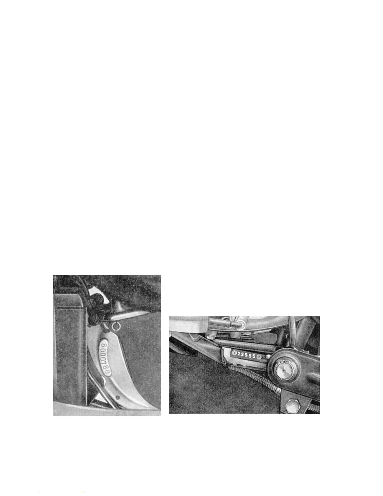
distance sleeve sits inbetween these two bearings to prevent them from being pulled together when
tightening the axle. When the distance sleeve doesn´t have the approved length anymore, the rings
are pressed against the balls of the bearing, causing sluggish behaviour of the bearings which
leads to their quick destruction. This concludes, that not only the wheel bearings need to be
checked, but also the distance sleeve (Turning the wheel with loosened and tightened axle),
because both can be responsible for sluggish behaviour of the wheel.
How to remove the bearings:
1. Remove wheel (see section 2.351).
2. Dismantle rear hub as described in section 2.341.
3. Hammer the axle out including the left hand side wheel bearing.
4. Pull out right bearing, using a puller. The new bearings need to be well lubed.
Installation is done in reverse order.
6 Parts support – technical support
All spare parts for the city scooter „SR 59-Berlin“ can only be obtained through authorized dealers
or specialized retail stores. This includes parts that are manufactured by IWL as well as third party
parts excluding tires. It is pointless to order directly from the manufacturer.
There are enough authorized dealers within the GDR (German Democratic Republic) that monitor
our vehicles throughout their warranty period, and are made available in the event of damage. For
technical inqiuries that are directed directly to the manufacturer, make sure to add the part number
of the regarding part and the frame number of the scooter as well as it´s current mileage.
Note: Scooterstation offers full parts support for the SR59 Berlin scooter within the US. If you need
parts you can contact us at: (503)-231-2768 or e-mail us at [email protected]
Image 67. engine nr. on the engine case Image 68. VIN number on the frame
The frame number is found on the left hand side of the frame just behind the rear traverse. The
engine number is found on the left hand side of the engine case on the bottom. The type plate is
localized on the hood under the seats.
 Loading...