

VEAB EA Series, EA 6, EA 9, EA 14, EA 21 Fitting Instructions Manual
...
EA
SE
GB
DE
FR
MONTERINGSANVISNING
VIKTIGT: Läs denna instruktion innan produkten monteras och ansluts.
........................................................................................................................... 2
FITTING INSTRUCTION
IMPORTANT: Please read this instruction before installation and connection of the product.
........................................................................................................................... 4
MONTAGEANLEITUNG
WICHTIG: Lesen Sie bitte diese Anweisung vor Montage und Anschluss.
........................................................................................................................... 6
INSTRUCTIONS DE MONTAGE
FI
ATTENTION: Lire attentivement cette notice avant de proceder à l'installation des batteries.
........................................................................................................................... 8
ASENNUSOHJE
TÄRKEÄÄ: Lue tämä ohje ennen tuotteen asentamista ja kytkemistä.
......................................................................................................................... 10
Art.nr. 172368-04

EA
SE
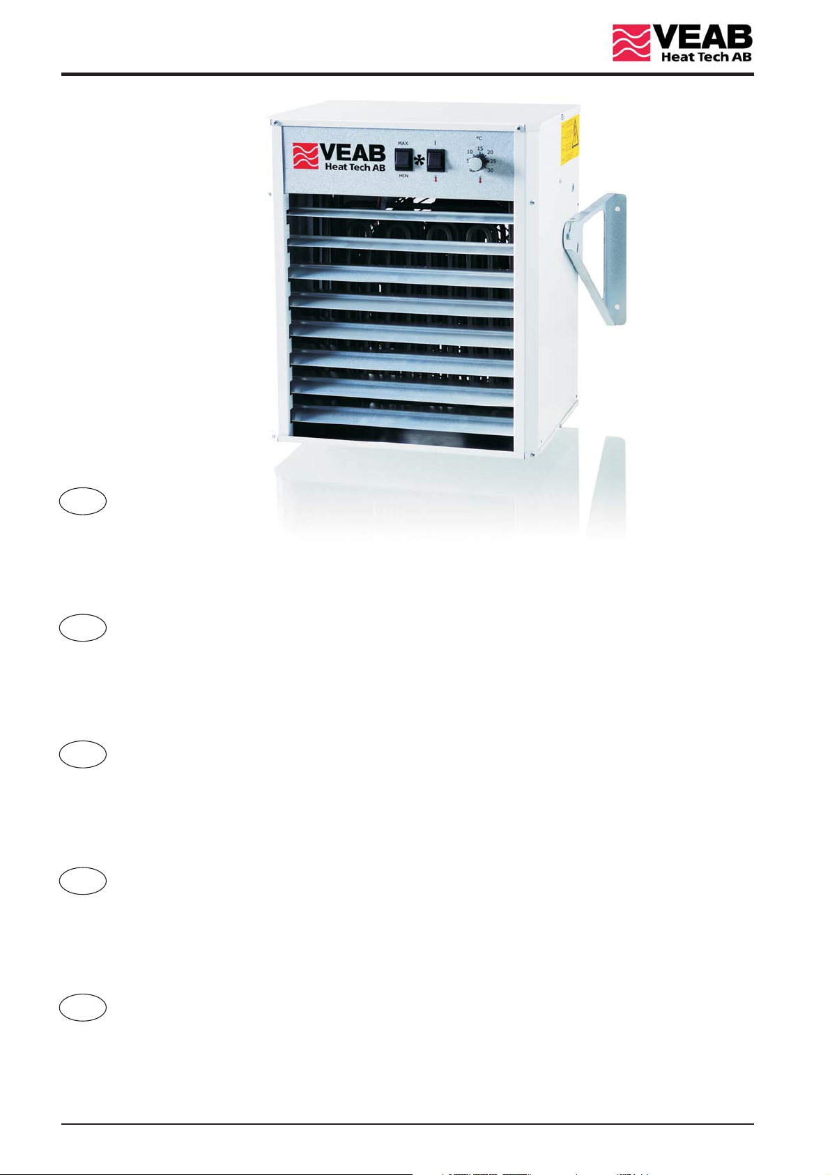
De väggmonterade värmefläktarna av typ finns i fem effektstorlekar;
6kW, 9kW, 14kW, 21kW och 30kW.
EA
Värmarna kan lutas 0...15° nedåt för att rikta luftflödet. Alternativt/dessutom kan värmarnas luftriktare användas för att
rikta luftflödet ytterligare nedåt. Med tillbehöret / kan luftflödet riktas även i horisontalled. Värmarens
EALH 10 EALH 20
konsoler medger takmontering som alternativt montagesätt.
Blandningsdel / kan användas för friskluftsinblandning.AWB 11 AWB 21
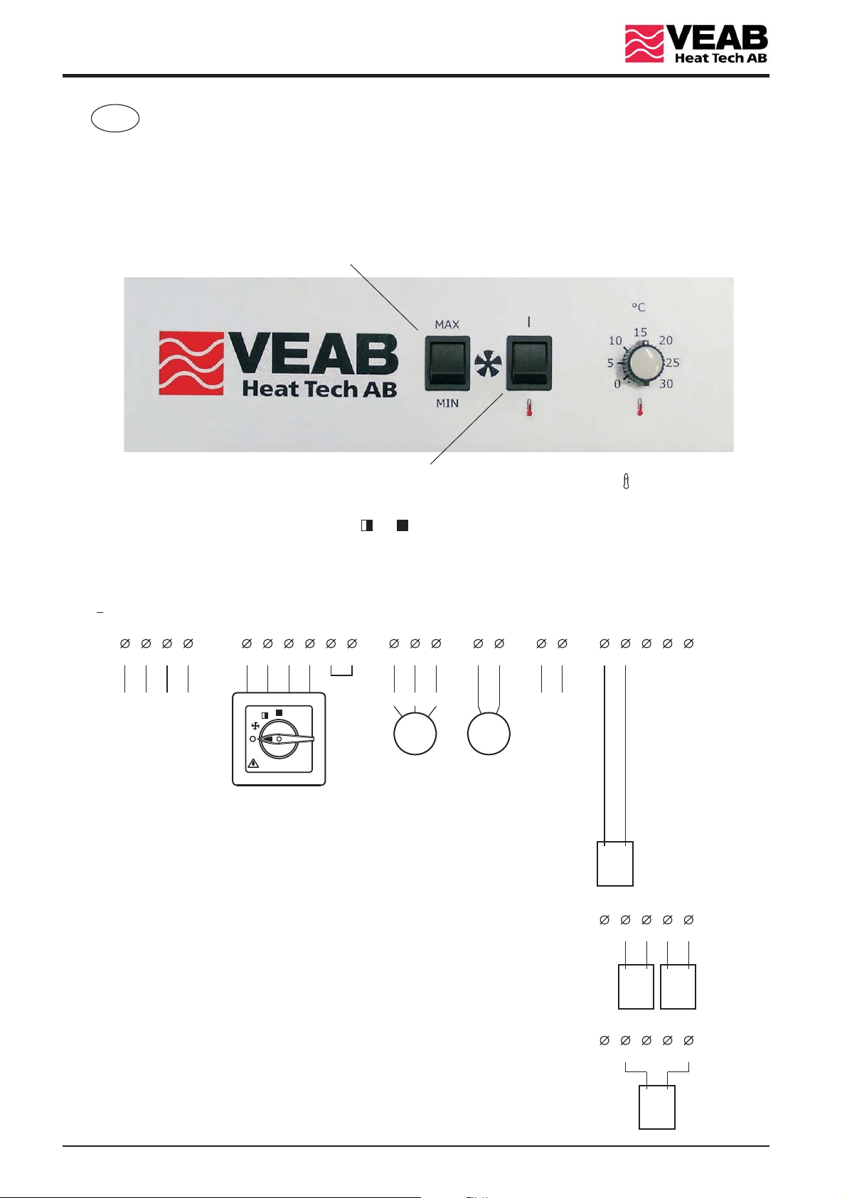
Fläktmotorns varvtal kan ändras mellan fullt varvtal (MAX) och reducerat varvtal (MIN) med omkopplaren på frontpanelen.
Fläktmotorns funktion kan ändras mellan kontinuerlig drift ( | ) och intermittent drift ( ).
Intermittent drift innebär att fläktmotorn startar när termostaten känner ett värmebehov och stannar när värmebehovet
upphör, förutsatt att omkopplaren står i läge eller .OK2
På sidorna 12-15 finns kopplingsschemor för samtliga modeller i -serien som visar värmarnas interna kopplingar.
Det finns två schemor vardera för och beroende på olika motoralternativ.
Bygeln mellan plint och finns endast på modellerna och . Genom att ta bort bygeln kopplas ett kontaktorsteg
(d.v.s. av märkeffekten) bort.
1
3
L1 L2NL3
5 6 EA 21 EA 30
400V 3N~
EA 6 EA 9
4
321
21 35
OK2
5
6 89713 14 1615 17 19 2018 21
123
EA
LN
Larm
MM
Spjällmotor
OK2
Alternativ 1
Potentiometern på frontpanelen används för inställning av temperaturens börvärde.
En extern rumsgivare, TG-R530 eller TG-R630, måste användas.
Alternativ 2
En extern potentiometer, TG-R430 eller TBI-30, används för inställning av
temperaturens börvärde. Potentiometern på frontpanelen är då bortkopplad
och dess inställning saknar betydelse. En extern rumsgivare, TG-R530 eller
TG-R630, måste användas.
Frånluftsfläkt
TG-R530
TG-R630
TG-R530
TG-R630
1917 18 20 21
2
312
TG-R430
TBI-30
Alternativ 3
En extern kombinerad rumsgivare och potentiometer, TG-R430, används för
inställning av temperaturens börvärde. Potentiometern på frontpanelen är
då bortkopplad och dess inställning saknar betydelse.
2
20
1917 18
13
21
TG-R430
Typ EA 6 EA 9 EA 14 EA 21 EA 30
Märks pänning 400V 3N~ 50Hz 400V 3N~ 50Hz 400V 3N~ 50Hz 400V 3N~ 50Hz 400V 3N~ 50Hz
Märkeffekt 6 kW 9 kW 14 kW 21 kW 30 kW
Reducerad effekt 3 kW 6 kW 7 kW 14 kW 20 kW
Märks tröm 8,7 A 13,0 A 20,3 A 30,4 A 43,5 A
A 157 mm 157 mm 220 mm 220 mm 220 mm
B 425 mm 425 mm 600 mm 600 mm 600 mm
W 390 mm 390 mm 555 mm 555 mm 555 mm
H 450 mm 450 mm 600 mm 600 mm 600 mm
D 270 mm 270 mm 375 mm 375 mm 465 mm
EA
Installation
1. Värmarna av typ är godkända för installation i torra och fuktiga rum samt i våtrum men inte i brandfarliga
EA
eller Ex-klassade utrymmen.
2. Värmaren måste anslutas till nätet med fast förlagd rund kabel. Kabelgenomföringar skall väljas av sådan typ
att värmarens kapslingsklass bibehålles.
3. En allpolig brytare med ett kontaktavstånd på minst 3mm måste ingå i den fasta installationen.
4. Installationen måste utföras av en behörig elektriker.
5. Värmaren är S-, CE- och EMC-märkt och är konstruerad i enlighet med följande standarder:
EN 60335-1 / EN 60335-2-30 / EN 61000-3-3 / EN 61000-6-2 / EN 61000-6-3
/ EN 61000-3-2 .
6. Denna produkt är inte avsedd att användas av barn eller personer med nedsatt fysisk eller mental förmåga
eller brist på erfarenhet och kunskap, om inte anvisningar angående produktens användning har getts av
person med ansvar för deras säkerhet eller att denna person övervakar handhavandet. Barn skall hållas under
uppsikt så att de inte kan leka med produkten.
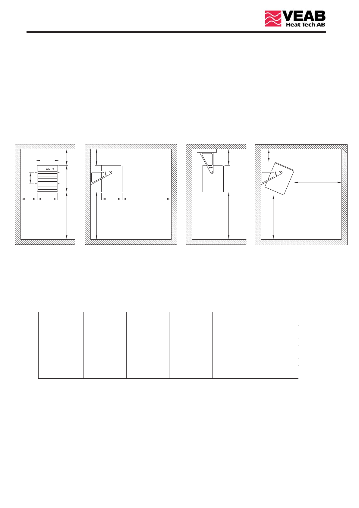
> 300 mm
> 2500 mm
> 1800 mm
A
> 300 mm
B
W
> 300 mm
H
> 1800 mm
> 300 mm
> 1800 mm
D
> 2500 mm
> 300 mm
> 1800 mm
Montering
1. Avstånden som anges i ovanstående skiss är min-mått. Avstånd mindre än angivna kan orsaka brand.
2. Värmarens kopplingsskåp måste alltid vara uppåt.
3. Värmaren får inte övertäckas eller manipuleras, för att undvika överhettning, brand eller el-chock.
Specifikation
Underhåll
Normalt behövs inget underhåll, förutom periodisk funktionstest och rengöring.
Överhettning
Värmaren är termiskt skyddad av ett överhettningsskydd med manuell återställning.
Om överhettningsskyddet har löst ut, skall följande beaktas:
1. Endast behörig .
2. Matningsspänningen måste kopplas bort.
3. Undersök noga orsaken till att överhettningsskyddet har löst ut.
4. När felet har åtgärdats, kan överhettningsskyddet återställas.
elektriker får öppna locket till kopplingsskåpet
3
EA
The series wall mounted fan heaters comes in five power ranges,
GB
The heaters can be tilted 0...15° downwards to direct the airflow. Alternatively/additionally the deflector can be used
to direct the airflow further downwards. The auxiliary deflector / can be used to direct the airflow
horizontally. It is possible to mount the heater in the ceiling with the standard brackets.
The mixing sections / can be used for fresh air mixing.AWB 11 AWB 21
The fan motor can be altered from full speed (MAX) to reduced speed (MIN) by using the switch on the front.
EA
i.e. 6kW, 9kW, 14kW, 21kW and 30kW.
EALH 10 EALH 20
The fan motor function can be changed from continuously running ( | ) to intermittent mode ( ).
Intermittent mode means that the fan motor starts when the thermostat switch on and stops when the thermostat switch off,
if the external function switch, , is in position or .OK2
On the pages 12-15 there is wiring diagrams for all the series heaters, showing the internal wiring.
There is two diagrams each for the and due to different fan motor alternatives.
The link at terminals and is only used in the and versions. By removing the link, one contactor
1
(i.e. of the rated power) is disconnected.
3
L1 L2NL3
5 6 EA 21 EA 30
400V 3N~
EA 6 EA 9
4
321
21 35
OK2
5
EA
6 89713 14 1615 17 19 2018 21
123
LN
Alarm
MM
Damper motor
OK2
Alternative 1
The potentiometer on the front is used to set the temperature.
An external room sensor, TG-R530 or TG-R630, must be used.
Exhaust fan
TG-R530
TG-R630
Alternative 2
An external potentiometer, TG-R430 or TBI-30, is used to set the temperature.
The potentiometer on the front is then disconnected and its setting das not affect
the temperature. An external room sensor, TG-R530 or TG-R630, must be used.
Alternative 3
An external combined room sensor and potentiometer, TG-R430, is used to
set the temperature. The potentiometer on the front is then disconnected
and its setting das not affect the temperature.
4
TG-R530
TG-R630
1917 18 20 21
2
20
1917 18
13
TG-R430
312
TG-R430
TBI-30
21

Type EA 6 EA 9 EA 14 EA 21 EA 30
Rated voltage 400V 3N~ 50Hz 400V 3N~ 50Hz 400V 3N~ 50Hz 400V 3N~ 50Hz 400V 3N~ 50Hz
Rated power 6 kW 9 k W 14 kW 21 kW 30 kW
Reduced power 3 kW 6 k W 7 k W 14 kW 20 kW
Rated current 8.7 A 13.0 A 20. 3 A 30.4 A 43.5 A
A 157 mm 157 mm 220 mm 220 mm 220 mm
B 425 mm 425 mm 600 mm 600 mm 600 mm
W 390 mm 390 mm 555 mm 555 mm 555 mm
H 450 mm 450 mm 600 mm 600 mm 600 mm
D 270 mm 270 mm 375 mm 375 mm 465 mm
EA
Installation
1. The heater series are approved for installation in dry, damp or wet rooms
EA but not in environments
where there is risk for fire or explosion.
2. The heater must be connected to the mains supply with a fixed installed round cable, which ensures that
the electrical protection class of the heater is retained.
3. An all phase breaker with a contact gap of at least 3mm must be included in the fixed installation.
4. The installation must be carried out by an authorised electrician.
5. The heater is S-marked, CE-marked, EMC-marked and designed in accordance with the following standards:
EN 60335-1 / EN 60335-2-30 / EN 61000-3-3 / EN 61000-6-2 / EN 61000-6-3
/ EN 61000-3-2 .
6. This appliance is not intended for use by persons (including children) with reduced physical, sensory or mental
capabilities, or lack of experience and knowledge, unless they have been given supervision or instruction
concerning use of the appliance by a person responsible for their safety. Children should be supervised to
ensure that they do not play with the appliance.
> 300 mm
> 2500 mm
> 1800 mm
A
> 300 mm
B
W
> 300 mm
H
> 1800 mm
> 300 mm
> 1800 mm
D
> 2500 mm
> 300 mm
> 1800 mm
Mounting
1. The distances shown in the above sketch are minimum. Distances less than shown may cause fire.
2. The connection box must always be positioned upwards.
3. The heater must not be covered or tampered to avoid overheating, fire or electric shock.
Specifications
Maintenance
No maintenance is required except a periodic functional test and cleaning.
Overheating
The heater is thermally protected by an overheat cut-out with manual reset.
If the overheat cut-out has tripped, the following should be observed:
1. Only an authorised electrician may open the connection box lid.
2. The mains power must be turned off.
3. Investigate carefully the reason for activation of the cut-out.
4. When the fault has been eliminated, the cut-out can be reset.
5
 Loading...