

Vdwall LVP615 Series Quick User Manual
地址:深圳市南山区科技园北区同方信息港 C 栋 5B 网址:www.videowall.cn
电话:
+86-755-2675 0210
传真:
+86-755-2675 0185
LVP615 系列快速使用指南
LVP615 serial quick user guide V1.0
In order to make sure users can quickly use LVP615 serial LED video processor, we prepared
the<LVP615 serial quick user guide>. About LVP615 deeply setup, adjustment and operation,
please refer to <LVP615 serial user manual>.
Front\rear panel button introduction
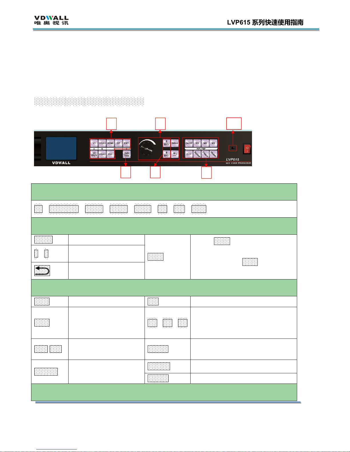
Front panel button
1
○
1
input signal selection keys:used to select corresponding input signals.
V1,V2/YPbPr,VGA1,VGA2,HDMI,DP,DVI,EXT.
○
2
setup key:used to set LVP615 parameters
Setup
Enter menu
knob
rotate knob can change current
setup item parameters
press knob ( OK key)to save
parameters.
↑,↓
Select setup items
Menu return key
○
3 other function keys
Auto
VGA auto adjustment
C/F
switching effect selection key
Take
Switch signals under
Pre+Take switching
mode
M1,M2,M3
PIP/PBP display mode key
Brt+ Brt-
Output brightness
adjustment key
On/Off
PIP/PBP function on/off key
Bypass
Full and part display
mode and switching key
Mosaic
Mosaic function on key
Freeze
Output image freeze key
○
4
remote sensing window: built in infrared receiver
2
333
4
地址:深圳市南山区科技园北区同方信息港 C 栋 5B 网址:www.videowall.cn
电话:
+86-755-2675 0210
传真:
+86-755-2675 0185
LVP615 系列快速使用指南
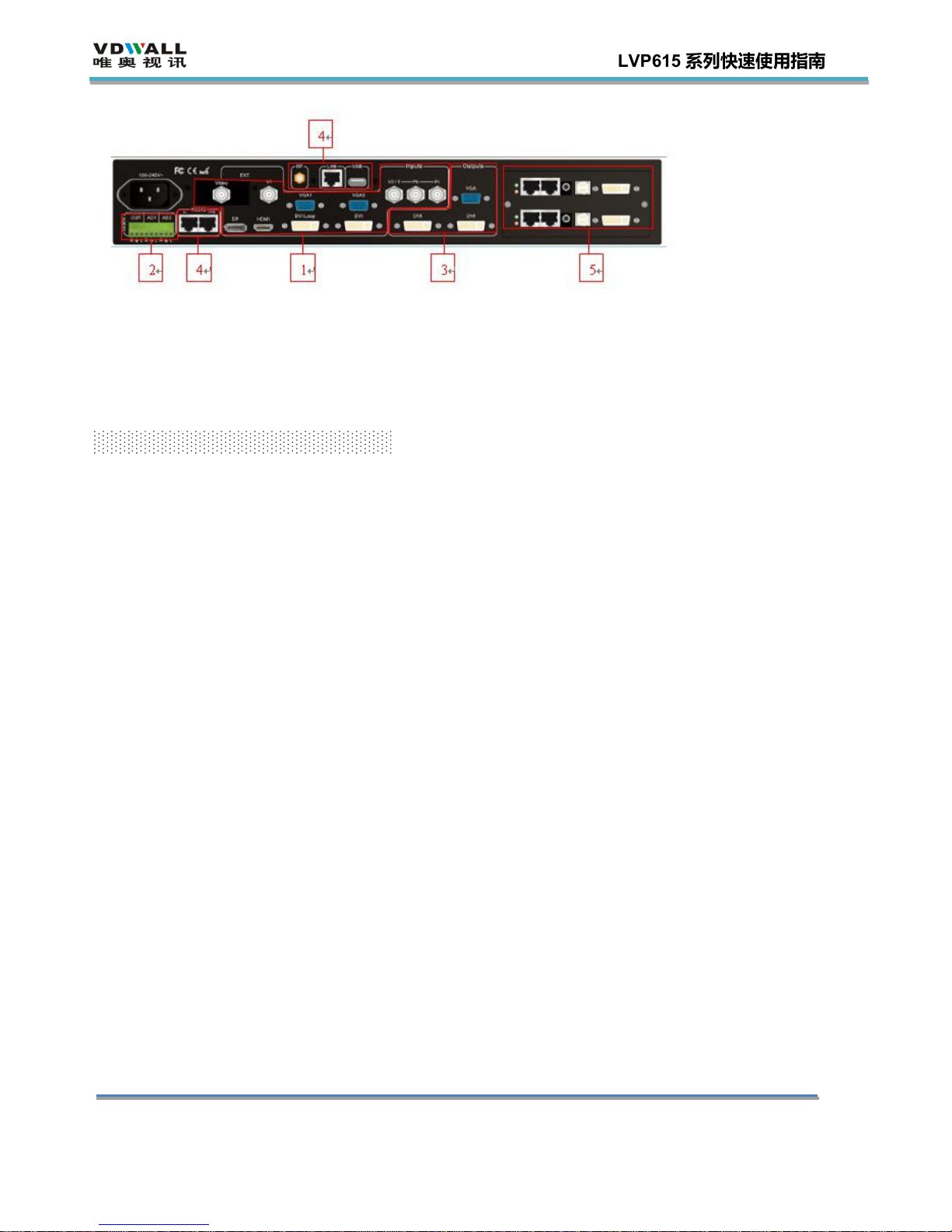
Rear panel button
1)video signal input ports 2)audio signals input and output 3)video signal outputs 4)
communication ports 5) sending card installation location
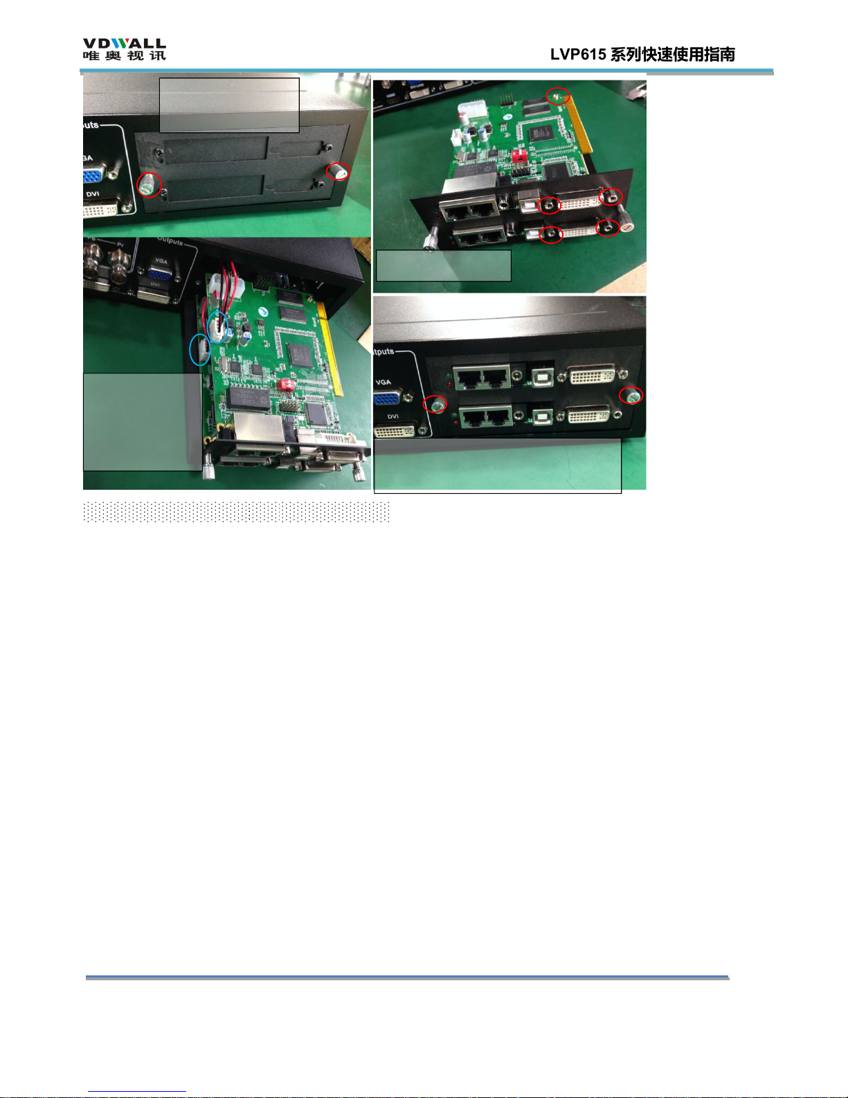
Step 1:sending card installation
1) Take out LVP615 processor, unscrew the sending card baffle screws and pull out the sending
card tray.
2) Install the sending card on the corresponding location of sending card tray and tighten the
screws.
3) Connect sending card +5 power cable and push the tray into the box.
4) Tighten the baffle screws. Then finish sending card installation.
地址:深圳市南山区科技园北区同方信息港 C 栋 5B 网址:www.videowall.cn
电话:
+86-755-2675 0210
传真:
+86-755-2675 0185
LVP615 系列快速使用指南
unscrew the screws
and pull out the tray
Install sending card
connect power
cable and push
the tray into the
box.
Tighten the fixed screws and finish
installation
Step 2:connect input and output signals
1) Turn off the power of all signal source devices.
2) Connect the output signals from video sources to corresponding video input ports of LVP615.
3) Connect LVP615 DVI outputs to DVI inputs of sending cards.
4) Connect sending card RJ45 cables to LED receiving cards .
5) Connect LVP615 VGA output to LCD display(used as monitor).
Refer to follow connection diagram:
 Loading...