

Vdwall LVP609 Series User Manual
SHENZHEN VDWALL CO., LTD www.videowall.cn www.vdwall.cn
LVP609 Series
4K 60Hz LED Video processor
User Manual
Tel: +86-755-2675 0210 / 2650 1506 / 2663 6668
Fax: +86-755-2675 0185
Add: Room B, 5th FIoor , Bldg . C , Tongfang lnformation Harbor, Nanshan Hi-Tech park , Nanshan District , Shenzhen
Web: en.vdwall.cn; www.videowall.cn

LVP609 series user manual Contents
2
Chapter 1: Safety precautions............................................................................................................................................ 3
Chapter 2: Packing list.......................................................................................................................................................... 4
Chapter 3: Hardware connection....................................................................................................................................... 5
3.1 Rear panel signal port picture..................................................................................................................5
3.2 Port description.......................................................................................................................................... 5
3.3 Hardware connection diagram.................................................................................................................7
3.4 Technical specification.............................................................................................................................. 7
3.5 Installation dimension................................................................................................................................9
Chapter 4 : Frontal panel button description............................................................................................................... 10
4.1 Frontal panel button sketch map...........................................................................................................10
Chapter 5: User basic operation instruction................................................................................................................ 13
5.1 Input signal selection...............................................................................................................................13
5.2 Output card operation............................................................................................................................. 15
5.3 Other function operation.........................................................................................................................15
Chapter 6 : User setup menu instruction...................................................................................................................... 18
6.1 Input card setup....................................................................................................................................... 18
6.2 Output card setup.................................................................................................................................... 20
6.3 Sync & Backup Setup............................................................................................................................. 23
6.4 System setup............................................................................................................................................26
Chapter 7: Mode instruction..............................................................................................................................................30
Appendix: Manual modification record................................................................................................................................31
Contents

LVP609 series user manual Chapter 1: Safety precautions
3
There is high voltage in the processor, to prevent any unexpected hazard, unless you are a
maintenance personnel, please do not open the cover of the device.
1. This device shall not encounter water sprinkle or splash, please do not place anything containing
water on this device.
2. To prevent fire, keep this device far from any fire source.
3. If this device gives out any strange noise, smoke or smell, please immediately unplug the power cord
from receptacle, and contact local dealer.
4. Please do not plug or unplug DVI signal cable if the device is powered on.
1. Please thoroughly read this manual before using this device, and keep it safe.
2. In the event of lighting or when you are not going to use the device for a long time, please pull the
power plug out of receptacle.
3. Nobody other than professional technicians can operate the device, unless they have been
appropriately trained or under guidance of technicians.
4. To prevent equipment damage or electric shock, please don’t fill in anything in the vent of the device.
5. Do not place the device near any water source or anywhere damp.
6. Do not place the device near any radiator or anywhere under high temperature.
7. To prevent rupture or damage of power cords, please handle and keep them properly.
8. Please immediately unplug power cord and have the device repaired, when
① Liquid splashes to the device.
②
The device is dropped down or cabinet is damaged.
③ Obvious malpractice is found or performance degrades.
Chapter 1: Safety precautions
Danger !
Warning !
Caution !

LVP609 series user manual Chapter 2: Packing list
4
Please unpack the product with care, and then check whether all the following items are included in the
package. If anything is found missing, please contact the dealer.
1.5m power cable x1
1.5m DVI cable x1
0.5m DVI cable ( depends
on DVI output quantity )
1.5m HDMI cable x1
1.5m DP cable x1
VGA to VGA+RCA cable x1
1.5m RS232-RJ45
convert cable X1
Products data U disk X1
Quick operation instruction
X1
Chapter 2:Packing list
Standard accessories
The accessories supplied with this product may differ from the following pictures, but they are applicable
for the regions where you live ( LED sending card is optional accessory )

LVP609 series user manual Chapter 3:Hardware connection
5
231
LVP609 supports 6 channels of video signal input as the table below:
Ports
Description
CVBS
1 channel of PAL / NTSC system composite video input
VGA
1 channel of PC analog signal input
DVI
1 channel of DVI digital signal input ( compatible with HDMI1.3 )
SDI
1 channel of SDI digital serial signal input ( compatible with HD-SDI /
3G-SDI )
HDMI1/HDMI2
1 channel of HDMI 2.0 digital signal input
DP
1 channel of DP1.2 digital signal input
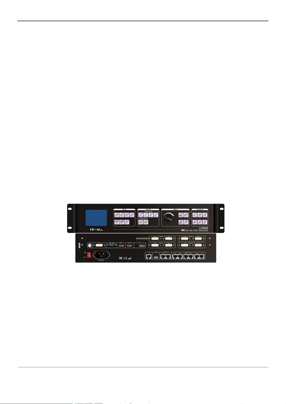
Chapter 3:Hardware connection
3.1 Rear panel signal port picture
1 Video input port ② Video output port ③ Communication port
○
3.2 Port description
3.2.1 Video signal input
Picture 3-1 Rear panel signal port picture

LVP609 series user manual Chapter 3:Hardware connection
6
Ports
Description
Out1, Out2
2 channels of DVI output port, used to connect LED sending card or
monitor
Ports
Description
LAN
Local area network TCP/IP network control port
USB
USB communication port
RS232 In
Serial port communication port, RS232 electrical level, connect the
RS232 interface of computer, for using PC software control
processor
RS232 Out
Serial port communication cascading output, RS232 electrical level,
when through single PC control several processors to use
GenLock In / Out
Synchronous lock frame signal input and output
3.2.1 Video signal input
LVP609 can assemble maximum 4 output cards, the serial number are K L M N. Every output card
can outputs 2 channels of DVI image signal, output port as the table below:
3.2.3 Communication port

LVP609 series user manual Chapter 3:Hardware connection
7
3.4 Technical specification
Input signal index
Quantity / type
1×CVBS
1×VGA(RGBHV
)
1×DVI(VESA /CEA-861
)
1×SDI(HD-SDI/3G-SDI)
2×HDMI 2.0(VESA /CEA-861
)
1×DP1.2(VESA
)
Composite video
system
PAL/NTSC
Composite Video
Amplitude / Impedance
1V(p_p)/ 75Ω
VGA format
PC(VESA
)
≤1920×1200_60Hz
3.3 Hardware connection diagram
Picture 3-3 hardware connection diagram

LVP609 series user manual Chapter 3:Hardware connection
8
VGA Amplitude /
Impedance
R, G, B = 0.7 V(p_p)/ 75Ω
DVI format
PC(VESA
)
≤1920×1200_60Hz
HDMI1.3(CEA-861
)
≤1080p_60Hz
SDI format
SMPTE259M-C
SMPTE 292M
SMPTE 274M/296M
SMPTE 424M/425M
480i_60Hz
576i_50Hz
720p、1080i、1080p
HDMI 2.0
(HDCP 2.2)
PC(VESA)
≤1920×1200_60Hz
HDMI2.0(CEA-861
)
≤3840x2160_60Hz
DP1.2
(HDCP 2.2)
PC(VESA
)
≤3840x2160_60Hz
Input port
CVBS:BNC
VGA:15pin D_Sub(female)
DVI:24+1 DVI_D
SDI:BNC/ 75Ω
HDMI 2.0: HDMI A mode
DP1.2: Display port1.2
Output signal index
Quantity / type
8×DVI
DVI format
1920×1080p_60Hz
Output port
DVI OUT:24+5 DVI_I
Sync port
GenLock
Other
Control port
RS232/USB/LAN
Input voltage
100-240VAC 50/60Hz
Overall power
consumption
≤100W
Environment
temperature
0-45 ℃
Environment humidity
15-85%
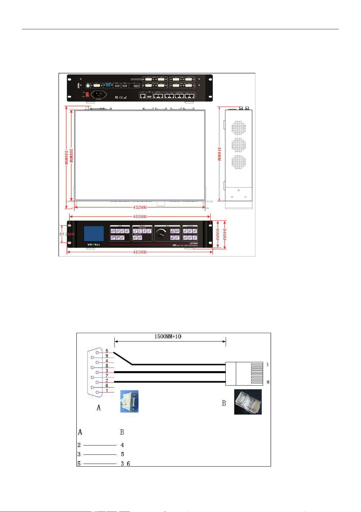
Product size
483( Length ) x 338( Width ) x 94( Height )mm
Packing size
540( Length ) x 400( Width ) x180( Height )mm
Weight
G.W.:9Kg, N.W.:5Kg
LVP609 series user manual Chapter 3:Hardware connection
9
Picture 3-5a installation dimension drawing
Picture 3-5b RS232 connection wires, wires order
Note: 1. A is RS232 female connector
2. B is RJ45 connector
3. Accord with emergency decree,
3.5 Installation dimension
RS232 connection wires, wires order

LVP609 series user manual Chapter 4 : Frontal panel button description
10
123
4
Picture 4-1 frontal Panel button sketch map
① Input signal selection button ② Output card function button
③
Setup button
④
Other function button
Input card signal source selection buttons, when select some signal source, the green indicator
light on relative button lit up. If the input port inputted valid signal, the indicator lit up normally, or it
will flicker.
Note: press
button twice processor will adjust VGA signal automatically.
Chapter 4 : Frontal panel button description
4.1 Frontal panel button sketch map
4.1.1 Input signal source selection button
4.1.2 Output card selection button
When select some output card, the red indicator light on relative button lit up, this moment you can
do relative operation to the output card.
 Loading...