

Page 1
1 / 37
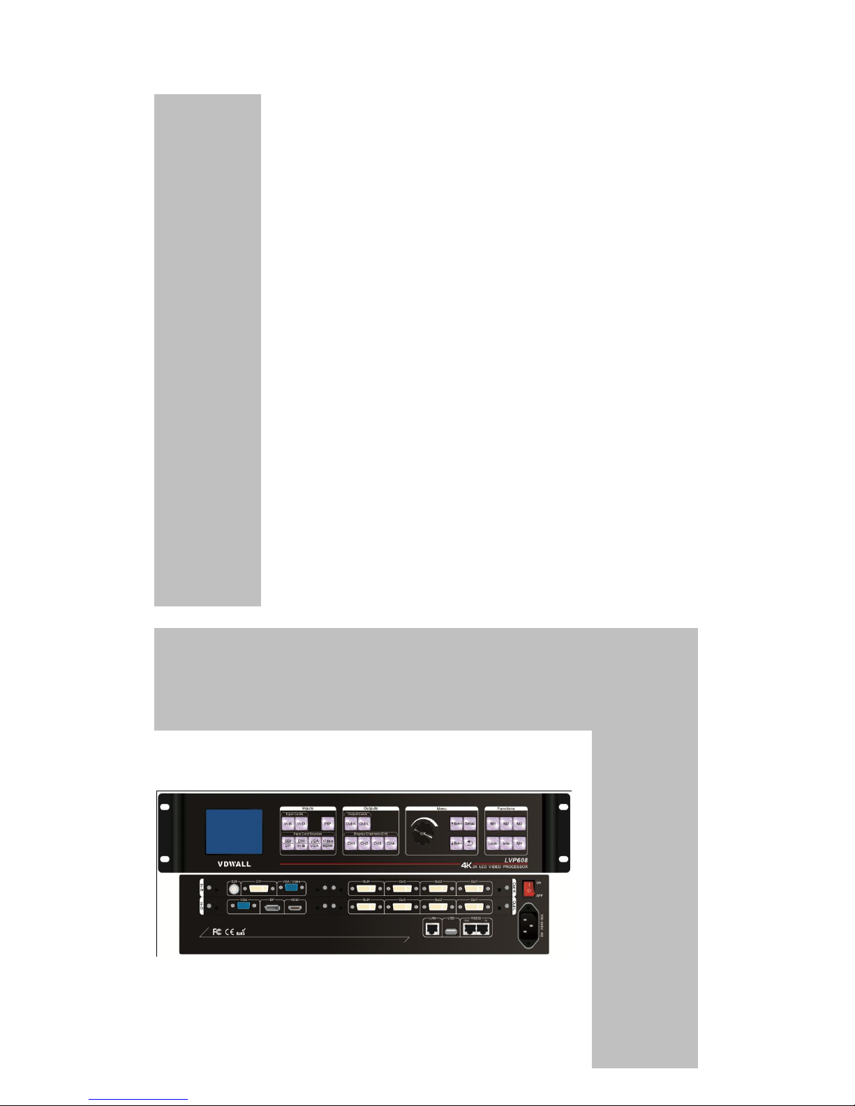
LVP608
4K2K LED Video Processor
User Manual
Page 2

2 / 37
Contents
Chapter1. Safety precautions--------------------------------------------------3-3
Chapter2. Items list----------------------------------------------------------------4-5
Chapter3. Hardware connection
3-1 System framework introduction ----------------------------5
3-2 Rear view ---------------------------------------------------5-6
3-3 Port description -------------------------------------------6-7
3-4 Connection diagram--------------------------------------7-7
3-5 Specifications-----------------------------------------------7-8
3-6 Dimension -------------------------------------------------8-9
Chapter4. Front panel
4-1 Button instruction ----------------------------------------9-11
Chapter5. Introduction to functions
5-1 Output port: four ports---------------------------------12-13
5-2 Output port: two ports(up/down) ------------------ -13-14
5-3 Output port: one port------------------------------------14-15
Chapter6. Basic operation introduction
6-1 Select input signals for input cards ------------------15-15
6-2 PIP setup of input cards --------------------------------15-15
6-3 Display mode setup of output cards -----------------16-16
6-4 Output port setup -----------------------------------------16-17
6-5 Brightness setup ------------------------------------------17-18
6-6 Automatic VGA calibration -----------------------------18-18
6-7 Button lock---------------------------------------------18-19
6-8 Check system information------------------------------19-19
Chapter7. User settings
7-1 Input card setup -------------------------------------------19-25
7-2 Output card setup -----------------------------------------25-32
7-3 System setup-----------------------------------------------32-38
Chapter8. Copyright information---------------------------------------------38-38
Page 3

3 / 37
Chapter1. Safety precautions
! Danger
There is high voltage in the processor, to prevent any unexpected hazard,
unless you are a maintenance personnel, please do not open the cover of
the device.
! Warning
1. This device shall not encounter water sprinkle or splash, please do not
place anything containing water on this device.
2. To prevent fire, keep this device far from any fire source.
3. If this device gives out any strange noise, smoke or smell, please
immediately unplug the power cord from receptacle, and contact local
dealer.
4. Please do not plug or unplug DVI signal cable if the device is
powered on.
! Caution
1. Please thoroughly read this manual before using this device, and keep
it well for future reference.
2. In the event of lighting or when you are not going to use the device for
a long time, please pull the power plug out of receptacle.
3. Nobody other than professional technicians can operate the device,
unless they have been appropriately trained or under guidance of
technicians.
4. To prevent equipment damage or electric shock, please don’t fill in
anything in the vent of the device.
5. Do not place the device near any water source or anywhere damp.
6. Do not place the device near any radiator or anywhere under high
temperature.
7. To prevent rupture or damage of power cords, please handle and
keep them properly.
8. Please immediately unplug power cord and have the device repaired,
when
1) Liquid splashes to the device.
2) The device is dropped down or cabinet is damaged.
3) Obvious malpractice is found or performance degrades.
Page 4
4 / 37
Chapter2. Items list
Please unpack the product with care, and then check whether all the following
items are included in the package. If anything is found missing, please contact
the dealer.
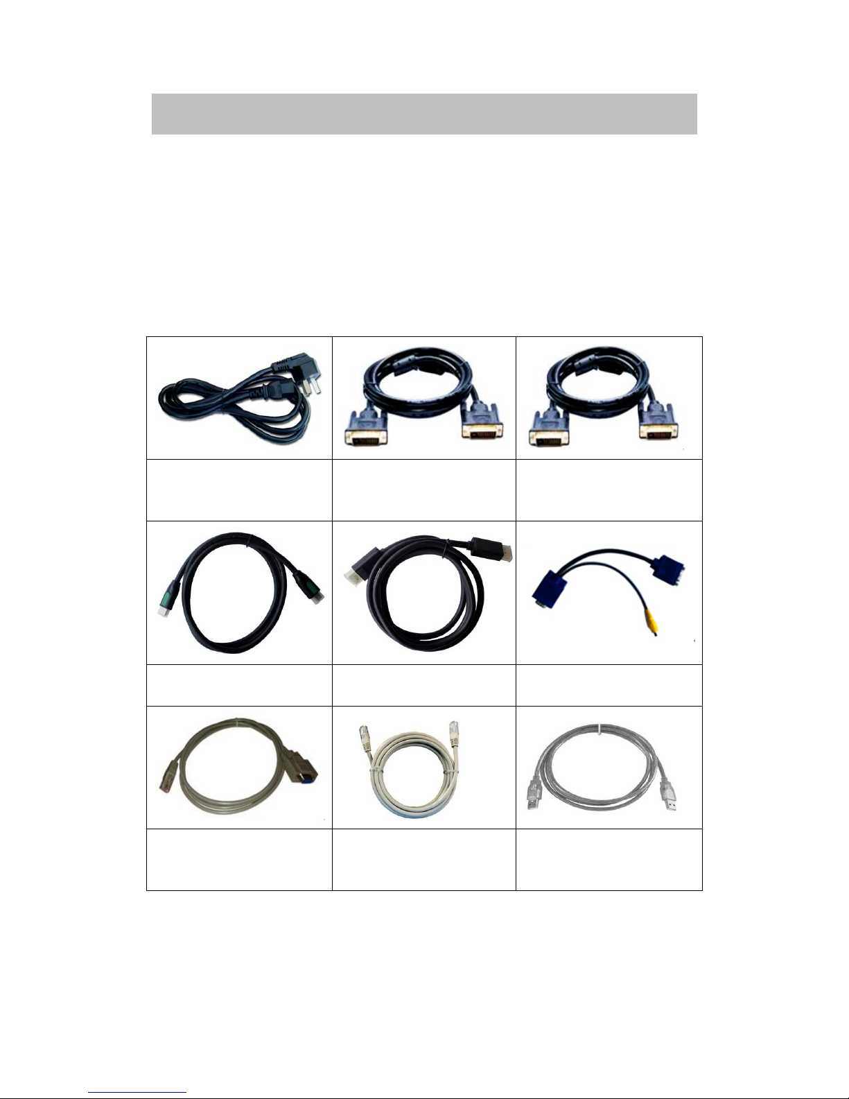
Standard accessories
The accessories supplied with this product may differ from the following
pictures, but they are applicable for the regions where you live.
1.5M Power Cable
X 1
1.5M DVI Cable X 1
0.5M DVI Cable
(Quantity depends
on output cards)
1.5m HDMI Cable
x1
1.5m DP Cable x1
VGA-VGA+RCA X 1
1.5M
RS232--RJ45
Convert Cable X 1
0.2M Network
Cable x1
1.5m USB Cable x1
Page 5
5 / 37
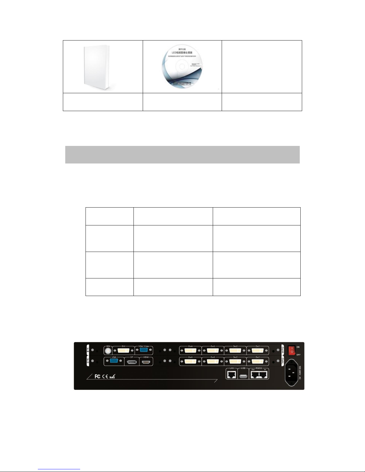
Operating manual
x1
Operating CD x1
Chapter3. Hardware connection
3-1 System framework introduction
Due to the plug-in design of input and output cards, the LVP608
configuration will depend on customer-specific requirements.
Types of
cards
Number
Function
Full HD
Video input
card
x1
Integrate multiple video
signals of different types
and formats
Ultra HD
Video input
card
x1
Integrate 4K2K video
signal
Output card
Maximum x2(DVI Ports
x8)
Output processed signals
to each display unit
Notice: when 2 output cards are pugged in, one of them can be used for
preview output.
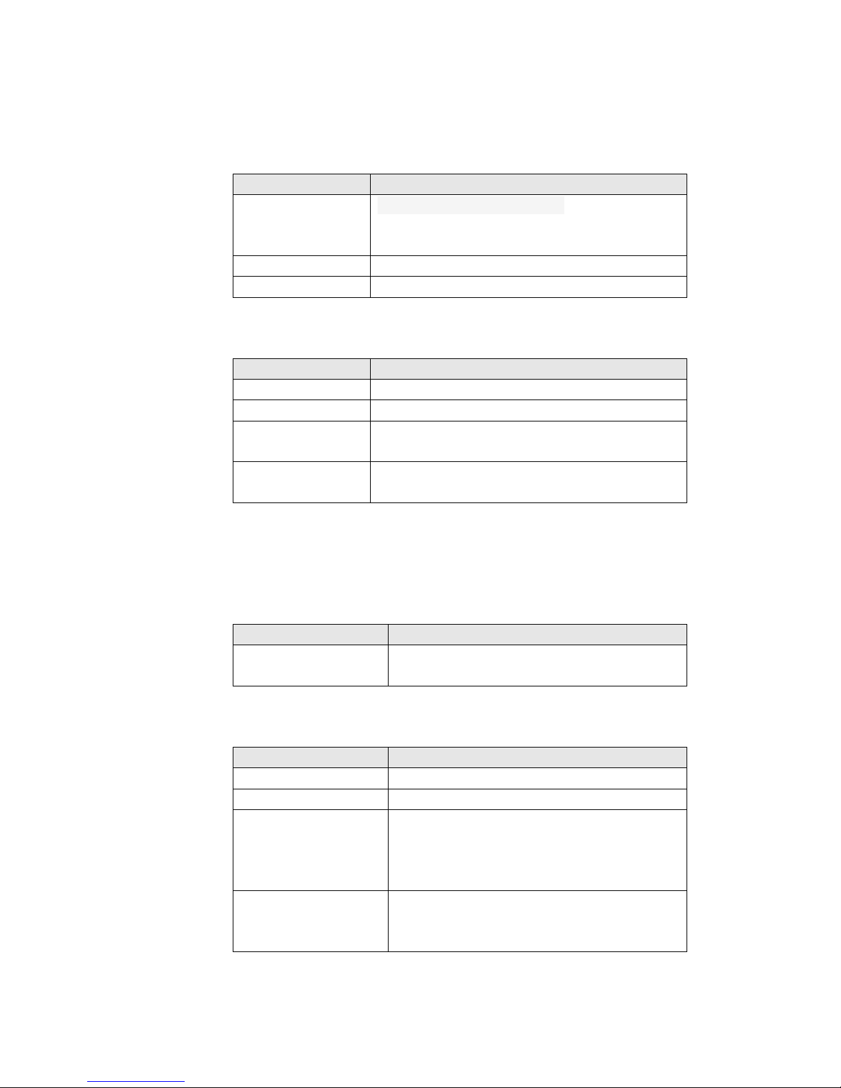
3-2 Rear view
3-3 Port description
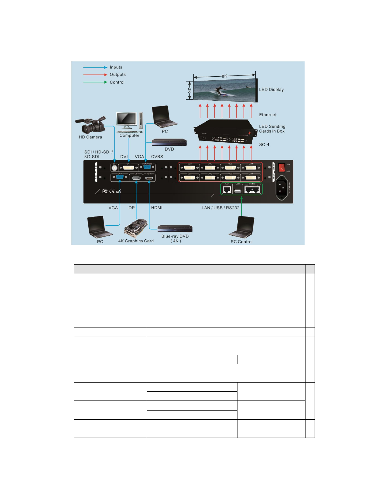
1) Input ports
LVP608 maximally supports 2 PCS of input cards, one full HD
Page 6
6 / 37
video input card(In-B) and one Ultra HD video input card(In-D).
Full HD video input card supports 4 input signals. The port
description is as follows:
Port
Description
VGA/Video
1* VGA(PC analog signal)
1*Composite(PAL/NTSC,VGA—VGA-RCA
adapter needed)
DVI/In-B
1 X DVI (HDMI1.3 compatible)
SDI
1x SDI/HD-SDI/3G-SDI digital signal input.
Ultra HD Video input card supports 3 external inputs and 1
internal DVI input.The port description is as follows:
Port
Description
VGA
1X PC analog signal input
DP
1X DP digital signal input(DP1.2)
HDMI
1X High-definition Multimedia signal input
(HDMI1.4)
DVI
1X DVI digital signal input, which is from the
output of Full HD Video Input Card In-B
2) Output port
LVP608 maximally supports 2 PCS of output cards (Out-K, Out-L)
and each card supports 4 DVI outputs. The port description is as
follows:
Port
Description
Out1-Out4
4 DVI outputs for connecting to sending
cards or monitors
3) Communication ports
Port
Description
LAN
LAN TCP/IP network control
USB
USB communication port
RS232 IN
Serial communication port, RS232
electric level, connect the RS232
interface of PC, use PC software to
control processor
RS232 Out
Serial communication looping out, RS232
electric level, use one PC to control all
processors
Page 7
7 / 37
3-4 Connection diagram
3-5 Specifications
Inputs
Type/Quantity
1×Video
2×VGA(RGBHV)
1×DVI(VESA /CEA-861)
1×HDMI(VESA /CEA-861)
1×DP(VESA)
1×SDI(SDI/HD-SDI/3G-SDI)
Video Standard
PAL/NTSC
Composite Video
Amplitude/Impedance
1V(p_p)/ 75Ω
VGA Format
PC(VESA Standard)
≤1920×1200_60Hz
VGA
Amplitude/Impedance
R、G、B = 0.7 V(p_p)/ 75Ω
DVI Format
PC(VESA Standard)
≤1920×1200_60Hz
HDMI1.3(CEA-861)
HDMI Format
PC(VESA Standard)
≤3840×2160_30Hz
HDMI1.4(CEA-861)
DP Format
Display Port 1.2 ( VESA
Standard)
≤3840×2160_30Hz
Page 8
8 / 37
SDI Format
SMPTE259M-C
SMPTE 292M
SMPTE 274M/296M
SMPTE 424M/425M
480i_60Hz
576i_50Hz
720p、1080i、1080p
Input Connectors
Video: 4-pin VGA
VGA:15-pin D_Sub(Female)
DVI:24+1 DVI_D
SDI:BNC/ 75Ω
HDMI: HDMI terminal A class
DP:Display Port
Outputs
Type/Quantity
8×DVI
Preview Output
1×DVI(Any one of them can be selected for preview
output)
DVI Resolution
1920×1080_60Hz
Output Connectors
DVI:24+1 DVI_D
Others
Control
RS232/USB/LAN
Input Voltage
100-240VAC 50/60Hz
Maximum Power
Consumption
≤60W
Environment Temperature
0-45 ℃
Environment Humidity
15-85%
Dimension
483(L) x 300(W) x 89(H)mm
Weight
Gross weight:7.7Kg, Net weight:5.4Kg
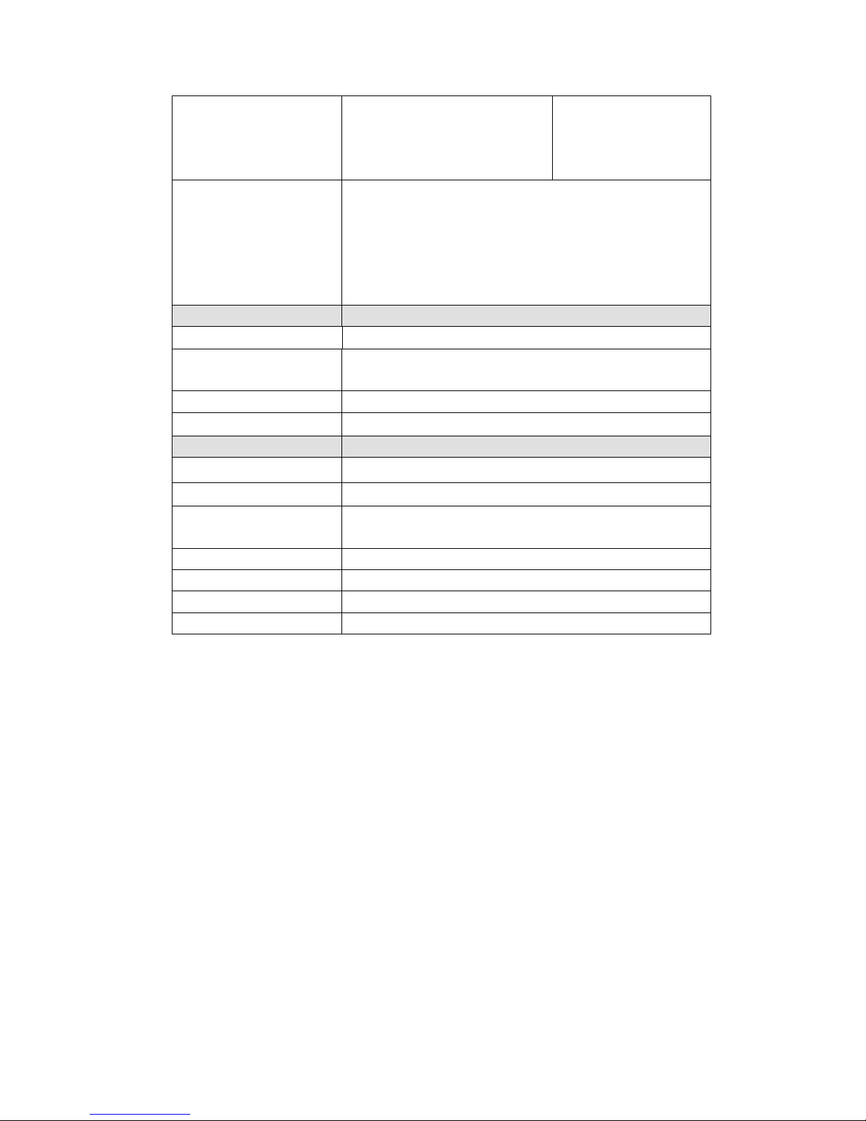
3-6 Dimension
Page 9
9 / 37
Chapter4. Front panel
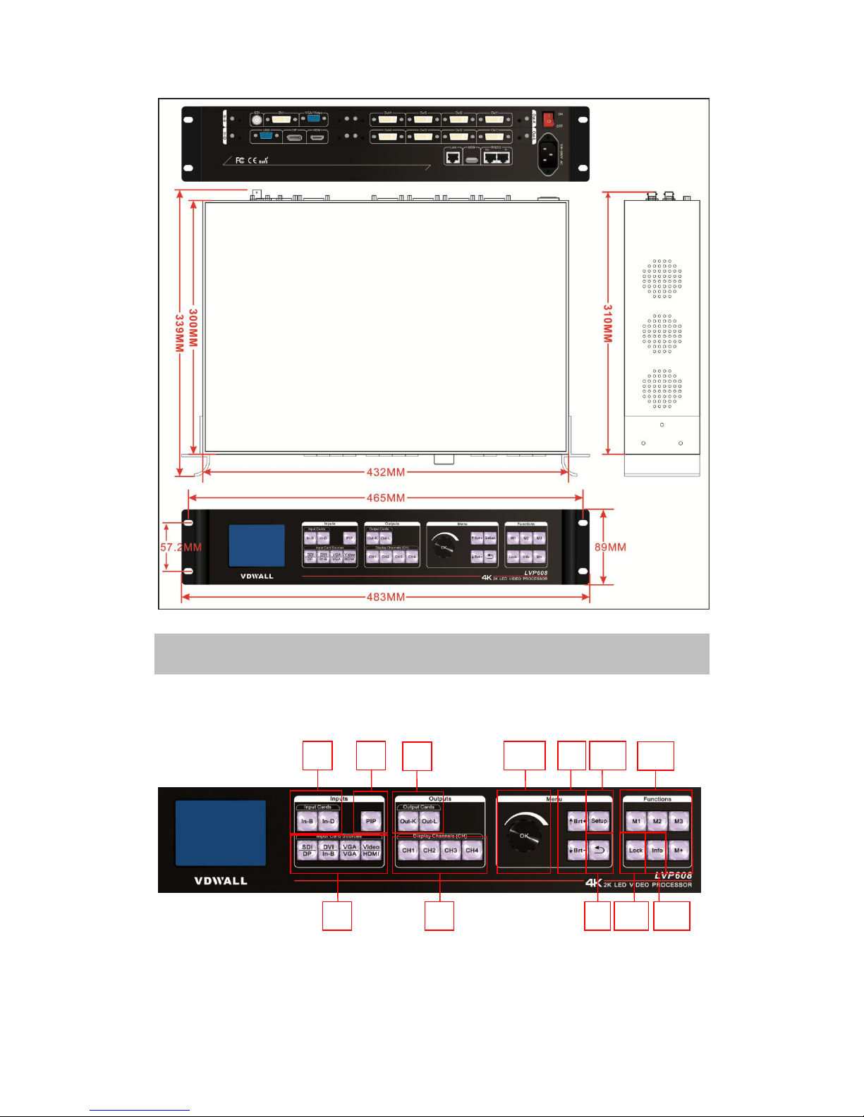
4-1 Button instruction
1. Input Cards (In-B, In-D): stand for 2 input cards accordingly. In-B is
Full HD Video Input Card. In-D is Ultra HD Video Input Card. When
pressing a button to select a card, if the red light of the indicator is on, it
1
2
3
5
4 6/7 8 10
9 12 13
11
Page 10

10 / 37
means the operation of the current input card is valid.
2. Input Card Sources(SDI/DP、DVI/In-B、VGA/VGA、Video/HDMI):
Input card selection,when selecting an input signal, if the green light of
the indicator is on. It means the signal is available.Otherwise the light
will flicker.
3. PIP: turn on or off the picture-in-picture function. If the indicator is on
and flicker, it means signals should be selected.After selected one signal
from “Input Card Sources”, it will be on green light. PIP signal can be
same as or different from the main pic signal.
4. Output Cards ( Out-K , Out-L ) : stand for 2 output cards
accordingly,.When select one card and the indicator is on red light, it
means the operation of the current output card is valid.
5. Display Channels (CH)(CH1、CH2、CH3、CH4):image output channel
selection. The indicator is on green light all the time when one output
channel is selected.Image output channel (CH), in the system of this
device, is also interpreted as “image layer”. The device can maximally
offer 4 image layers (CH1, CH2, CH3, CH4) which can be overlapped.
6. Knob: turn it to adjust the parameters on the menu.
7. OK: press it to confirm the operation.
8. ↑Brt+,↓Brt-:versatile buttons, “↑” and “↓” are used to select an item
under setting situation. While Brt+ and Brt- are used to adjust the
brightness under operation situation.
9. :return to the previous menu.
10. Setup :enter the setup menu.
11.M1,M2,M3,M+:display mode select.
There are 16 display modes in total. Press M1, M2 or M3 to directly
select display mode 1, 2 or 3 and the indicator light is on. Mode
4—16 can be selected by pressing M+ to enter mode invoking menu
and rotating the knob.
Each display mode has display image status and its related
parameters:Size and location of image layer (input image will be
cropped, so the new size and location will be created and output).
Page 11
11 / 37
12.Lock:press the button and the indicator is on red light, all the other
buttons are locked. Press the button again for 3 times, all the other buttons
are unlocked and the light is off.
13.Info:display the system information. We can press button to check
different status and parameters of the device.
Chapter5. Introduction to functions
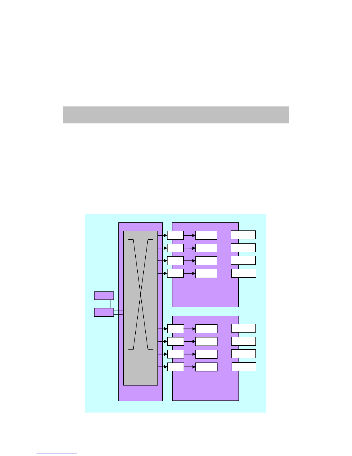
LVP608 can maximum support 2 Input Cards (each card includes
SDI/DP, DVI/In-B, VGA, Video/HDMI) and 2 Output Cards.
The output signal of In-B enters to the DVI input port of In-D, as the DVI
input signal of In-D.
The signal In-D output divided into left half part (Left) and right half part
(Right),enter Baseboard matrix, through Interaction and distribution of
matrix, as the input signal of Output Card (In1,In2, In3, In4).
Baseboard
Output card Out-K
In-B
In-D
Baseboard
matrix
(Matrix K,
Matrix L)
In1
CH1
In2
In3
In4
CH2
CH3
CH4
Out1
Out2
Out3
Out4
Output card Out-L
In1
CH1
In2
In3
In4
CH2
CH3
CH4
Out1
Out2
Out3
Out4
Page 12
12 / 37
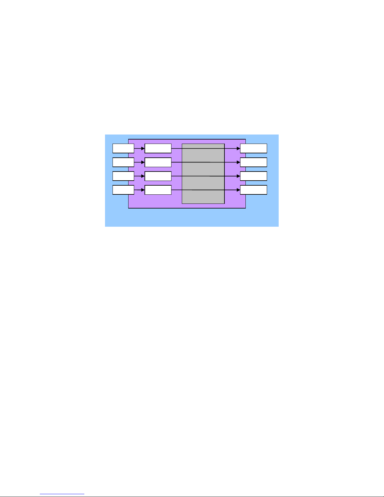
The output card design of LVP608 has 3 different output modes. In this
device, the design currently has: four ports, two ports (up/down) and one
port, customers can select output modes according to the project
requirements.
5-1 Output port: four ports
Four output ports are:
Out1 = CH1 Out2 = CH2 Out3 = CH3 Out4 = CH4
This means:
Output port1 (Out1) outputs image from image layer1 (CH1)
Output port2 (Out2) outputs image from image layer2 (CH2)
Output port3 (Out3) outputs image from image layer3 (CH3)
Output port4 (Out4) outputs image from image layer4 (CH4)
Image layers (CH1, CH2, CH3, CH4) correspond to input channel
s(In1, In2, In3, In4).
Image layer (CH) can crop the image of input channel and output
to 4 output ports separately.
Four ports can apply to LED screen of Width <=3840, Height
<=2160 (2X2)
Four ports can apply to LED screen of Width <=7680, Height
<=1080 (4X1)
In1
CH1
Out1
Output port: four ports
In2
In3
In4
CH2
CH3
CH4
Out 2
Out 3
Out 4
Page 13
13 / 37
If you only use 2 of the four ports, it can apply to LED screen of
Width <=3840, Height <=1080 (2x1)
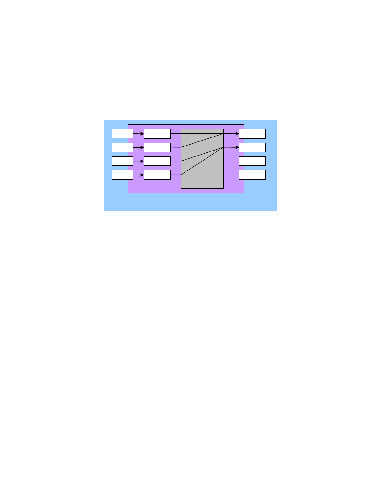
5-2 Output port: two ports (up/down)
Two output ports are:
Out1 = CH1 + CH2 Out2 = CH3 + CH4
This means:
Out1 outputs the image generated by 2 image layers overlapped
(CH1 and CH2);
Out2 outputs the image generated by 2 image layers overlapped
(CH3 and CH4);
Out3 and Out4 no output.
Image layers (CH1, CH2, CH3, CH4) correspond to input channel
s(In1, In2, In3, In4).
Image layer (CH) crop the image of input channel and output to 2
output ports separately.
Two ports can apply to LED screen of Width <=1920, Height
<=2160 (1x2)
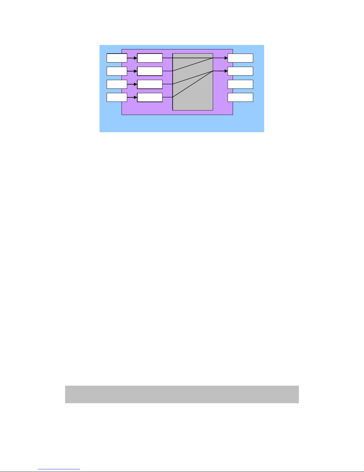
5-3 Output port: one port
In1
CH1
Out1
Output port: two ports (Up/Down)
In2
In3
In4
CH2
CH3
CH4
Out 2
Out 3
Out 4
Page 14
14 / 37
Out1 = CH1 + CH2 Out2 = CH3 + CH4
This means:
Out1 outputs the image generated by 2 image layers overlapped
(CH1 and CH2);
Out2 outputs the image generated by 2 image layers overlapped
(CH3 and CH4);
Out3 and Out4 no output.
Only connect Out 1 to Sending Card.
Image layers (CH1, CH2, CH3, CH4) correspond to input
channels (In1, In2, In3, In4).
Image layer (CH) cut out the image of input channel and output
to 2 output ports separately.
One port can apply to LED screen of Width <=1920, Height
<=1080.
Chapter6. Basic operation introduction
When system starts, it will automatically detect and identify the number
In1
CH1
Out1
Output port: One port
In2
In3
In4
CH2
CH3
CH4
Out 2
Out 3
Out 4
Page 15
15 / 37
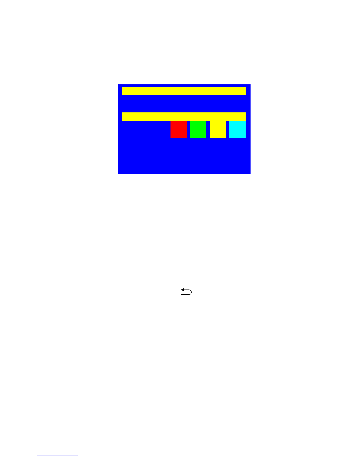
and location of input cards and output cards. The LCD panel will display the
information accordingly. The introduction of basic operations is based on full
configuration (2 PCS of input cards and 2 PCS of output cards) and the
default menu will be as follows when system starts:
6-1 Select input signals for input cards
Press “SDI/DP、DVI/In-B、VGA、Video/HDMI” to select a signal,
and press “In-B or In-D” to select an input card for operation.
6-2 PIP setup for input cards
Press “PIP” and then select “SDI/DP、DVI/In-B、VGA、Video/HDMI” as
the signal for PIP. Press “In-B, In-D” to select an input card for
operation.
6-3 Display mode setup of output cards
There are 16 display modes in total, press “M1,M2 or M3”to directly
select display mode 1,2 or 3,and the indicator light is on; Mode 4-16 can
be selected by pressing “M+” to enter mode invoking menu and rotating
the knob. “OK” to confirm and “ ” to quit. The menu of “Display
mode setup” is as follows:
Each display mode of LVP608 includes the status and relative
parameter of displaying image:
The size and location of image layer (include: crop the size and
location of input image, then output the size and location of
the copped image)
In-D(Input Card D)
Source: In-B 0s
Status: No PIP/Text
Out-K(Output Card K)
Out Channel: CH1 CH2 CH3 CH4
In Card: Left Right Left Right
Display Mode: M1
Output Port: 4 Ports
Out1=CH1 Out2=CH2 Out3=CH3 Out4=CH4
Page 16

16 / 37
6-4 Output port setup
Press “Setup” to enter “user settings”, press “ ↑ ,↓ ”to select
“Output Card Setup”, press “OK” to enter its sub menu. Press “↑,↓”to
select “Advanced Setup”, press “OK” to enter its sub menu, press “↑,↓”
to select “Output Port”, turn the knob to select “OK” to enter the
confirmation sub menu.
Press Out-K, Out-L to select the output card.
On the confirmation sub menu, press “OK” to change output port.
Tips
-------------------------------------Data will reset
Press <OK> to reset
Press <return> to cancel
--------------------------------------
Output Card Advanced Setup
Out-L
--------------------------------------
1.Output port 1 Port
2.Auto Detect Off
3.CH Reset
4.Refresh Data
5.Reset Data
-----------------------------------
Out-L Display Mode:M1
INV.METH.:Single Card
--------------------------------------
M1 M2 M3 M4
M5 M6 M7 M8
M9 M10 M11 M12
M13 M14 M15 M16
--------------------------------------
Page 17
17 / 37
Notice: to change the output port will restore the data of the output
card, don’t change it if unnecessary.
6-5 Brightness setup
The adjusting range of brightness is 0-32, “0” stands for the lowest
brightness, press “Brt+”to increase the brightness or “Brt-”to lower it. To
make sure of the complete grey level of the output images, the default is
set as “32”and we can turn the knob to select one or two output cards for
brightness adjusting.
6-6 Automatic VGA calibration
When the current input signal is VGA and it is valid, press “VGA” to enter
the confirmation menu of VGA automatic calibration, press “VGA” one
more time to confirm calibration and then to quit the menu, The
menu is as follows:
6-7 Button lock
Press “Lock”, other buttons will be locked in case of wrong operation.
On the menu of “Button Lock”, press “Lock” three times to quit the lock
state. When buttons are locked, only LAN, RS232 and USD
communication are available in case of the conflict between remote
control and panel control. When commands are sent from
Tips
-------------------------------------VGA Auto Adjust
Press <VGA> to start
Press <return> to cancel
--------------------------------------
Out-L Brightness
--------------------------------------
1.Brightness 32
--------------------------------------
Page 18

18 / 37
remote,buttons will be automatically locked.
The menu is as follows:
6-8 Check system information
Press “Info” to enter the menu of system information, and then press “↑,
↓”to turn the page and “ ” to quit. The menu is as follows:
Chapter7. User settings
User settings are used for the overall system setup, these settings
consist of 3 parts: input card, output card and the system. On the default
menu, when system starts, press “Setup” to enter the menu of “User
settings” and“↑,↓” to select settings, press “OK” to confirm, and “ ” to
quit the menu.
Following is the detailed instruction of each setting:
7-1 Input card setup
Press “Setup” to enter the menu of “User settings”, “↑,↓”to select
System Info
-------------------------------------Model: LVP608
Version: V0.0.1
IP: 192.168.1.10
Mask: 255.255.255.0
Gate: 192.168.1.1
Mac: 76-64-77-1A-2B-3C
Device ID: 1
--------------------------------------
Button Lock
-------------------------------------Keypad Invalid
LAN Valid
RS232 Valid
USB Valid
--------------------------------------
Page 19

19 / 37
“Input Card Setup”, press “OK” to enter the sub menu. Press “In-B or
In-D” to select an input card to change its settings.
1.Set the size and location of main image
On the menu of “Input Card Setup”, press “↑,↓” to select “Main
Setup”, and “OK” to enter the sub menu.
Press “↑,↓” to select the setting, turn the knob to ajust and then press
“OK” to confirm.
Input Card Main Setup
In-B
--------------------------------------
1.Hori Width 666 -> 888
2.Hori Start 88
3.Vert Height 666
4.Vert Start 66
--------------------------------------
I In-B Setup
--------------------------------------
1.Main Setup
2.PIP Setup
3.Image Setup
4.Text Setup
5.Advanced Setup
--------------------------------------
Setup
--------------------------------------
1.Input Card Setup
2.Output Card Setup
3.System Setup
--------------------------------------
Page 20

20 / 37
2.Set the size and location of PIP
On the menu of “Input Card Setup”, press “↑,↓”to select “PIP
Setup”, press “OK” to enter the sub menu.
Press “↑,↓”to select the setting, turn the knob to ajust, and press “OK”
to confirm.
3.Set brightness, contrast and color
On the menu of “Input Card Setup”, press “↑,↓”to select “ Image
Setup”, and “OK” to enter the sub menu.
Input Card PIP Setup
In-B
--------------------------------------
1.Hori Width 666 -> 888
2.Hori Start 88
3.Vert Height 666
4.Vert Start 66
--------------------------------------
In-B Setup
--------------------------------------
1.Main Setup
2.PIP Setup
3.Image Setup
4.Text Setup
5.Advanced Setup
--------------------------------------
Page 21

21 / 37
Press “↑,↓”to select the setting, turn the knob to adjust, and press “OK”
to confirm.
The adjusting range of brightness, contrast and color is
0-100.Brightness adjusting is only valid for the selected input card, if the
adjusting is wrong, press “Reset” to return to the default.
Notice: to change the settings is not recommended, unless brightness
adjusting through the panel buttons can’t meet customers’
requirements.
4. Set text on/off, text source and text mode
On the menu of “Input Card Setup”, press “↑,↓”to select “Text Setup”,
press “OK” to enter the sub menu.
Input Card Image Setup
In-B
--------------------------------------
1.Brightness 50
2.Contrast 50
3.Saturation 50 –> 56
4.Reset
--------------------------------------
In-B Setup
--------------------------------------
1.Main Setup
2.PIP Setup
3.Image Setup
4.Text Setup
5.Advanced Setup
--------------------------------------
Page 22
22 / 37
Press “↑,↓”to select the setting, turn the Knob to ajust, press “OK” to
confirm.
5.Advanced setup
On the menu of “Input Card Setup”, press “↑,↓”to select “ Advanced
Setup”, press “OK” to enter the sub menu.
Set fade time
On the menu of “Input Card Advanced Setup”, press “↑,↓”to
In-D Setup
--------------------------------------
1.Main Setup
2.PIP Setup
3.Image Setup
4.Text Setup
5.Advanced Setup
--------------------------------------
Input Card Text Setup
In-B
--------------------------------------
1.Text Off
2.Text Source DVI
3.Text Mode <Threshold
4.Text R 8
5.Text G 4
6.Text B 8
--------------------------------------
In In-B Setup
--------------------------------------
1.Main Setup
2.PIP Setup
3.Image Setup
4.Text Setup
5.Advanced Setup
--------------------------------------
Page 23

23 / 37
select “ Fade Time”, turn the knob to adjust, and press “OK” to confirm.
HDMI hot plug on/off
On the menu of “Input Card Advanced Setup”, press “↑,↓” to
select “HDMI hot plug”, turn the knob to ajust, and press “OK” to
confirm.
Notice: when LVP608 is switching signal source, it will send a “hot plug
signal” to HDMI device, so the device can update HDMI signal flow and
working normally. In this situation, a small number of HDMI devices can’t
working normally in extended desktop, then you can turn it off. Generally
we don’t suggest you to turn it off.
Set DP version
On the menu of “Input Card Advanced Setup”, press “↑,↓” to
select “DP Version”, turn the knob to adjust, and press “OK” to confirm.
Input Card Advanced Setup
In-D
--------------------------------------
1.Fade Time 0.5s
2.HDMI hot plug Off
3.DP Version 1.2
4.Refresh Data
5.Reset Data
--------------------------------------
Input Card Advanced Setup
In-D
--------------------------------------
1.Fade Time 0.5s
2.HDMI hot plug Off
3.DP Version 1.2
4.Refresh Data
5.Reset Data
--------------------------------------
Page 24

24 / 37
Notice: only when input card is In-D, you can set DP version.
Refresh data
On the menu of “Input Card Advanced Setup”, press “↑,↓” to
select “Refresh Data”, and press “OK” to confirm.
Notice: sometimes when users change input cards by themselves, the
data of new input cards might be inconsistent with that of the
system. “Refresh Data” will then update the system data to be
consistent with that of the new input cards. Generally we don’t
suggest customers to change it.
Reset input card
On the menu of “Input Card Advanced Setup”, press “↑, ↓”
to select “Reset Data” and then press “OK” to enter the sub menu.
Input Card Advanced Setup
In-D
--------------------------------------
1.Fade Time 0.5s
2.HDMI hot plug Off
3.DP Version 1.2
4.Refresh Data
5.Reset Data
-------------------------------------
Input Card Advanced Setup
In-D
--------------------------------------
1.Fade Time 0.5s
2.HDMI hot plug Off
3.DP Version 1.2
4.Refresh Data
5.Reset Data
--------------------------------------
Page 25

25 / 37
When entering the sub menu of “Reset Data”, press OK to start to
reset .
Notice: sometimes when users change input cards by themselves, the
data of new input cards might be inconsistent with that saved by
the system. “Reset data” will restore the data of new input cards
to the factory default. The operation is only valid for a single
input card, so it won’t affect the data of other input cards.
7-2 Output card setup
Press “Setup” to enter the menu of “User Settings”, “↑, ↓” to
select “Output Card Setup” and then “OK” to enter the sub menu.
Tips
-------------------------------------Data will reset
Press <OK> to reset
Press <return> to cancel
--------------------------------------
Input Card Advanced Setup
In-D
--------------------------------------
1.Fade Time 0.5s
2.HDMI hot plug Off
3.DP Version 1.2
4.Refresh Data
5.Reset Data
--------------------------------------
Page 26

26 / 37
1.Set the size and location of input image for output card
On the menu of “Output Card Setup”, press “↑,↓” to select “Input Image
Setup” and “OK” to enter the sub menu.
Press “↑,↓” to select the setting, turn the knob to ajust, and press “OK”
to confirm.
2.Set the size and location of output image for output card
Output Card Input Image Setup
Out-K/M1/CH1
--------------------------------------
1.Hori Width 1920
2.Hori Start 0
3.Vert Height 2160
4.Vert Start 0
--------------------------------------
Out-K Setup
--------------------------------------
1.Input Image Setup
2.Output Image Setup
3.Matrix Setup
4.Clock Setup
5.Advanced Setup
-------------------------------------
Setup
--------------------------------------
1.Input Card Setup
2.Output Card Setup
3.System Setup
--------------------------------------
Page 27
27 / 37
On the menu of “Output Card Setup”, press “↑,↓” to select “Output
Image Setup”, press “OK” to enter the sub menu.
Press “↑,↓” to select the setting,turn the Knob to ajust, and press “OK”
to confirm.
3.Output card matrix setup
On the menu of “Output Card Setup”, press “↑,↓” to select “Matrix
Setup”, press “OK” to enter the sub menu.
Output Card Matrix Setup
Out-K/M1
--------------------------------------
1.CH1 Left
2.CH2 Right
3.CH3 Left
4.CH4 Right
--------------------------------------
Output Card Output Image Setup
Out-K/M1/CH1
--------------------------------------
1.Hori Width 1920
2.Hori Start 0
3.Vert Height 2160
4.Vert Start 0
-------------------------------------
Out-K Setup
--------------------------------------
1.Input Image Setup
2.Output Image Setup
3.Matrix Setup
4.Clock Setup
5.Advanced Setup
--------------------------------------
Page 28

28 / 37
4.Clock setup
On the menu of “Output Card Setup”, press “↑,↓” to select “Clock
Setup”, press “OK” to enter the sub menu.
Press “↑,↓”to select the setting, turn the knob to ajust, press “OK” to
confirm.
Notice: clock setup is only used when display is out of sync,if display is
out of sync,please set “Frame Sync” as In1,and also select
“System Clock”as In1.
5.Advanced setup
On the menu of “Output Card Setup”, press “ ↑ , ↓ ” to select
“Advanced Setup”, press “OK” to enter the sub menu. Press “Out-K” or
“Out-L” on front panel to select the output card to set, press “CH1, CH2,
CH3 or CH4” to select the channel to set.
Output Card Clock Setup
Out-K/CH1
--------------------------------------
1.Frame Sync Off
2.System Clock Main Board
--------------------------------------
Out-K Setup
--------------------------------------
1.Input Image Setup
2.Output Image Setup
3.Matrix Setup
4.Clock Setup
5.Advanced Setup
--------------------------------------
Page 29
29 / 37
Set output port of output card
On the menu of “Output Card Advanced Setup”, press “↑,↓” to
select “Output port”,turn the knob to ajust, press “OK” to enter the sub
menu.
On the menu of “confirming output port”, press “OK” to change output
port.
Notice: change output port will cause the data reset, don’t change it if
Tips
-------------------------------------Data will reset
Press <OK> to reset
Press <return> to cancel
-------------------------------------
Output Card Advanced Setup
Out-L
--------------------------------------
1.Output port 1 Port
2.Auto Detect Off
3.CH Reset
4.Refresh Data
5.Reset Data
--------------------------------------
Out-K Setup
--------------------------------------
1.Input Image Setup
2.Output Image Setup
3.Matrix Setup
4.Clock Setup
5.Advanced Setup
--------------------------------------
Page 30
30 / 37
unnecessary.
Auto detect of signals for output card
On the menu of “Output Card Advanced Setup”, press “↑,↓”to
select “Auto detect”, turn the knob to adjust, and press “OK” to confirm.
Notice: normally “Auto detect” is off, it is mainly used for malfunction
detec of input card. When “Auto detect” is on and In-D has
malfunction, the screen will be blank.
Channel reset
On the menu of “Output Card Advanced Setup”, press “↑,↓” to
select “CH Reset”, press “OK” to confirm.
Notice: input signals for output cards will be briefly unstable when
making changes in “Matrix K Setup” or “Matrix L Setup” and it will
lead to blurred or blank screen. “CH Reset” will restore the
system. Normally this operation is not necessary.
Refresh data
On the menu of “Output Card Advanced Setup”, press “↑,↓”to select
Output Card Advanced Setup
Out-L
--------------------------------------
1.Output port 1 Port
2.Auto Detect Off
3.CH Reset
4.Refresh Data
5.Reset Data
--------------------------------------
Output Card Advanced Setup
Out-L
--------------------------------------
1.Output port 1 Port
2.Auto Detect Off
3.CH Reset
4.Refresh Data
5.Reset Data
--------------------------------------
Page 31
31 / 37
“Refresh Data”, press “OK” to confirm.
Notice: sometimes when users change output cards by themselves, the
data of new output cards might be inconsistent with that of the
system. “Refresh Data” will then update the system data to be
consistent with that of the new output cards.
Reset data
On the menu of “Output Card Advanced Setup”, press “↑,↓” to select
“Reset Data”, press “OK” to enter the sub menu.
On the sub menu of “Reset Data”, press “OK” to reset.
Tips
-------------------------------------Data will reset
Press <OK> to reset
Press <return> to cancel
--------------------------------------
Output Card Advanced Setup
Out-L
--------------------------------------
1.Output port 1 Port
2.Auto Detect Off
3.CH Reset
4.Refresh Data
5.Reset Data
--------------------------------------
Output Card Advanced Setup
Out-L
--------------------------------------
1.Output port 1 Port
2.Auto Detect Off
3.CH Reset
4.Refresh Data
5.Reset Data
-------------------------------------
Page 32

32 / 37
Notice: sometimes when users change output cards by themselves, the
data of new output cards might be inconsistent with that saved by
the system. “Reset data” will restore the data of new output cards
to the factory default. The operation is only valid for a single
output card, so it won’t affect the data of other output cards.
7-3 System setup
Press “Setup” on front panel to enter “user settings”, press “↑,↓”to
select “System Setup”, press “OK” to enter the sub menu.
1.IP address
On the menu of “System Setup”, press “↑,↓” to select “IP Setup”,
press “OK” to enter the sub menu.
Press “↑,↓” to select the setting, turn the knob to ajust, and press “OK”
to confirm.
System Setup
--------------------------------------
1.IP Setup
2.MASK Setup
3.Gate Setup
4.MAC Setup
5.Advanced Setup
--------------------------------------
Setup
--------------------------------------
1.Input Card Setup
2.Output Card Setup
3.System Setup
--------------------------------------
Page 33

33 / 37
2. Subnet mask address
On the menu of “System Setup”, press “↑,↓” to select “MASK Setup”,
press “OK” to enter the sub menu.
Press “↑,↓”to select the setting, turn the knob to ajust, press “OK” to
confirm.
3. Gateway address
MASK Setup
--------------------------------------
1.Address1 255
2.Address2 255
3.Address3 255
4.Address4 0
-------------------------------------
System Setup
--------------------------------------
1.IP Setup
2.MASK Setup
3.Gate Setup
4.MAC Setup
5.Advanced Setup
-------------------------------------
IP Setup
--------------------------------------
1.Address1 192 -> 190
2.Address2 168
3.Address3 1
4.Address4 100
--------------------------------------
Page 34

34 / 37
On the menu of “System Setup”, press “↑,↓”to select “Gate
Setup”, press “OK” to enter the sub menu.
Press “↑,↓”to select the setting, turn the knob to ajust, press “OK” to
confirm.
4.MAC
On the menu of “System Setup”, press “↑,↓”to select “MAC Setup”,
press “OK” to enter the sub menu.
GATE Setup
--------------------------------------
1.Address1 192
2.Address2 168
3.Address3 1
4.Address4 1
--------------------------------------
System Setup
--------------------------------------
1.IP Setup
2.MASK Setup
3.Gate Setup
4.MAC Setup
5.Advanced Setup
--------------------------------------
Page 35
35 / 37
Press “↑,↓”to select the setting,turn the knob to ajust, press “OK” to
confirm.
5. Advanced setup
On the menu of “System Setup”, press “↑,↓”to select “Advanced
Setup”, press “OK” to enter the sub menu.
System Setup
--------------------------------------
1.IP Setup
2.MASK Setup
3.Gate Setup
4.MAC Setup
5.Advanced Setup
--------------------------------------
MAC Setup
--------------------------------------
1.Address1 76
2.Address2 64
3.Address3 77
4.Address4 1A
5.Address5 2B
6.Address6 3C
-------------------------------------
System Setup
--------------------------------------
1.IP Setup
2.MASK Setup
3.Gate Setup
4.MAC Setup
5.Advanced Setup
--------------------------------------
Page 36

36 / 37
System language
On the menu of “System Advanced Setup”, press “↑,↓”to select
“ 语言 Language”, turn the knob to ajust, press “OK” to confirm. You
can select English or Chinese as system language.
Device ID
On the menu of “System Advanced Setup”, press “↑,↓” to select
“ Device ID”, turn the knob to adjust, press “OK” to confirm.
Reset data
On the menu of “System Advanced Setup”, press “↑,↓” to select
“ Reset Data”, press “OK” to confirm.
System Advanced Setup
--------------------------------------
1.语言 Language English
2.Device ID 1
3.Reset Data
-------------------------------------
System Advanced Setup
--------------------------------------
1.语言 Language English
2.Device ID 1
3.Reset Data
--------------------------------------
Page 37

37 / 37
On the sub menu of “ Reset Data”, press “OK” to reset.
Notice: “Reset Data” will restore all the system data to the factory default.
Normally it is not suggested to use.
Chapter8. Copyright information
The copyright of this manual is owned by SHENZHEN VDWALL CO.,
LTD., unless with prior consent of VDWALL, nobody is permitted to
copy or use any part or all of the information contained herein.
This manual is provided for reference only, VDWALL reserves right
to change the product appearance, dimensions and specifications
from time to time without notice to users.
Tips
-------------------------------------Data will reset
Press <OK> to reset
Press <return> to cancel
--------------------------------------
System Advanced Setup
--------------------------------------
1.语言 Language English
2.Device ID 1
3.Reset Data
--------------------------------------
 Loading...