

LVP615U
LED HD Video Processor
User Manual
V1.0

LVP615U
使用说明
2
Contents
Chapter 1: Safety precautions
-------------------------------------------------- 4
Chapter 2: Item list
-------------------------------------------------------------------- 5
Chapter 3: Hardware connection
3.1 Rear view-------------------- --------------------------------------------------- 6
3.2 Port description----------------------------------------------------------------- 6
3.3 Hardware connection diagram----------------------------------------------- 8
3.4 Specifications---------------------------------------------------------------------9
3.5 Product dimensions------------------------------------------------------------11
Chapter 4: Front panel and remote control instructions
4.1 Front panel buttons and remote control schematic----------------------- 13
4.2 Remote control operation instructions---------------------------------------- 15
Chapter 5: Basic user instructions
5.1 Input signals selection ---------------------------------------------------------- 17
5.2 PIP/PBP operation--------------------------------------------------------------- 21
5.3 Mosaic operation----------------------------------------------------------------- 22
5.4 Other basic user operation----------------------------------------------------- 23
Chapter 6: Setup menu instructions
6.1 Output image setting------------------------------------------------------------ 26
6.2 Input video signal setting------------------------------------------------------- 30
6.3 Text overlay setting-------------------------------------------------------------- 33
6.4 Image quality setting------------------------------------------------------------ 35
6.5 Audio setting----------------------------------------------------------------------- 36
6.6 Communication setting---------------------------------------------------------- 37
6.7 Language setting------------------------------------------------------------------ 38
6.8 Advance setting------------------------------------------------------------------- 49
6.9 PIP/PBP setting-------------------------------------------------------------------- 42
6.10 Mosaic setting------------------------------------------------------------------- 43

LVP615U
使用说明
3
Chapter 7: Remote control instructions
7.1 Hardware communication-------------------------------------------------- 48
7.1.1 RS232 and USB-------------------------------------------------------------- 49
7.1.2 Wired network---------------------------------------------------------------- 50
7.1.3 WIFI connection--------------------------------------------------------------- 51
7.2 LVP615U series PC control software instructions----------------------
58
7.2.1 Control method---------------------------------------------------------------- 58
7.2.2 Software interface instructions-------------------------------------------- 59
7.3 APP remote control---------------------------------------------------------- 76
7.3.1 Connection----------------------------------------------------------------------- 77
7.3.2 APP control instructions-------------------------------------------------------80
Chapter 8 Copyright information---------------------------------------------------97
Appendix: modify the record table ----------------------------------------------------- 98

LVP615U
使用说明
4
Chapter 1: Safety precautions
!Danger
There is high voltage in the processor, to prevent any unexpected
hazard, unless you are maintenance, please do not open the cover
of the device.
!Warning
1. This device shall not encounter water sprinkle or splash,
please do not place anything containing water on this device.
2. To prevent fire, keep this device far from any fire source.
3. If this device gives out any strange noise, smoke or smell,
please immediately unplug the power cord from receptacle, and
contact local dealer.
4. Signal cables are not hot swappable.
!Caution
1. Please thoroughly read this manual before using this device,
and keep it well for future reference.
2. In the event of lighting or when you are not going to use the
device for a long time, please pull the power plug out of
receptacle.
3. Nobody other than professional technicians can operate the
device, unless they have been appropriately trained or under
guidance of technicians.
4. To prevent equipment damage or electric shock, please don’t
fill in anything in the vent of the device.
5. Do not place the device near any water source or anywhere damp.
6. Do not place the device near any radiator or anywhere under
high temperature.
7. To prevent rupture or damage of power cords, please handle and
keep them properly.

LVP615U
使用说明
5
8. Please immediately unplug power cord and have the device
repaired, when
1) Liquid splashes to the device.
2) The device is dropped down or cabinet is damaged.
3) Obvious malpractice is found or performance degrades.
Chapter 2 Item List
Please unpack the product carefully, then check whether all the following
things are included in the package. If anything is found missing, please contact
the dealer.
Standard accessories
The accessories supplied with this LED Video Processor may differ from
the figures contained in the User’s Manual, but they are applicable for the
regions where you live.(LED sending card is optional)
1.5m power cord*1
1.5m DVI cable*1
0.5m DVI cable*1
1.5m RS232 to RJ45
adapter cable*1
User manual *1
CD*1
Remote control *1
Audio connector *1
BNC-RCA adapter *3

LVP615U
使用说明
6
Chapter 3 Hardware connection
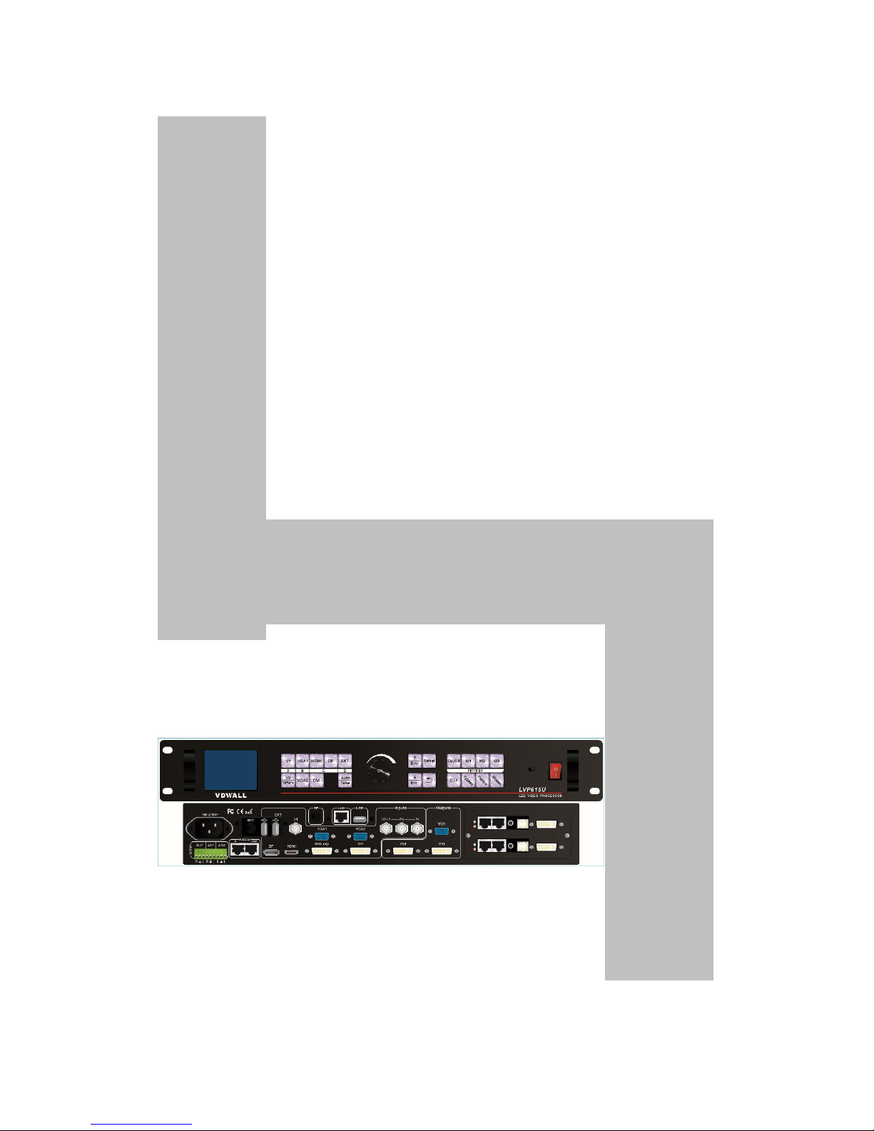
3.1 Rear view
13524
4
3.2 Ports description
3.2.1 Video signal inputs (INPUT)
LVP615U supports 8 video signals input as follows:
Port
Description

LVP615U
使用说明
7
V1
1*Composite Video (PAL/ NTSC)
V2 / YPbPr
1* Composite video (PAL/ NTSC) or analog
component video input
VGA1~VGA2
2 * PC analog signal
DVI
1* DVI ( PC digital signal)
HDMI
1*HDMI (HD digital signal)
DP
1*DisplayPort( digital signal input)
EXT.
1* Extended PAL/NTSC composite video input
3.2.2Audio input signals(AUDIO)
LVP615U supports 5-channel stereo audio inputs switching. Of
which, 3channels are DP, HDMI and USB input. The other 2 channels are AD1,
AD2 external audio input. AD1 and AD2 can be mapped to any one of signal
inputs, and will be switched synchronous to the selection of video input signals.
3.2.3 Video signal output
Port
Description
VGA OUT
1-channel analog RGBHV signal output,
which can be connected to a local display
device for monitoring (it is strongly
recommended to use this port when
operating and setting LVP615U).
DVI OUT1 /
DVI OUT2
2 same DVI digital graphic signal output,
it can be connected to external 2 LED
transmission cards or LED transmission
boxes.
DVI Loop OUT
1-channel computer DVI digital signal
loop output

LVP615U
使用说明
8
3.2.4 Other ports
Port
Description
LAN
TCP/IP local area network control
interface
USB
USB communication port
RS232 IN
Serial communication interface, used to
connect the RS232 port of PC to realize
PC software control.
RS232 LOOP
Serial communication cascading output
for connecting the RS232 IN of next unit,
through single PC can control several
units.
RF
Antenna interface of wireless control
function
RF 2
Network intelligent module
3.3 Hardware connection diagram

LVP615U
使用说明
9
3.4 Specifications

LVP615U
使用说明
10
Inputs
Nums / Type
2×Video
1×YPbPr
2×VGA(RGBHV)
1×DVI(VESA /CEA-861)
1×HDMI(VESA /CEA-861)
1×DP(VESA)
1*EXT ( USB)
Video system
PAL/NTSC
Composite Video
Amplitude Impedance
1V(p_p)/ 75Ω
VGA format
PC(VESA standard)
≤2048×1152_60Hz
VGA Amplitude
Impedance
R、G、B = 0.7 V(p_p)/ 75Ω
YPbPr format
SD/HD(CEA -861)
≤1920x1080p_60Hz
YPbPr Amplitude
Impedance
Y=1V(p_p)/ 75Ω
Pb= 0.35V(p_p)/ 75Ω
Pr= 0.35V(p_p)/ 75Ω
DVI format
PC(VESA standard)
≤2304×1152_60Hz
Custom output format
Width≤3840 ,
Height≤1920
HDMI format
PC(VESA standard)
≤1920×1080_60Hz
HDMI1.3(CEA-861)
DP format
Display Port 1.1 ( VESA
standard)
≤1920×1080_60Hz
USB
video format
MKV/TS/M2TS/TP/TRP/AVI
/WMV/RM/RMVB/MPEG/M
PG/MP4/VOB/MOV/ISO/DA
T/ASF
Video encoding format
H.265 AVC HD、VC-1(WMV
HD) 、 MPEG-2 HD 、
MPEG-1、MPEG-4、Xvid

LVP615U
使用说明
11
Picture format
JPG 、 PNG 、 BMP , max
resolution 15million.
Input connectors
Video:BNC
YPbPr:BNC×3
VGA:15pin D_Sub(female)
DVI:24+1 DVI_D
HDMI:HDMI port A type
DP:Display Port
USB:USB A type
VGA/DVI format
1024×768_60Hz/75Hz
1280×1024_60Hz/75Hz
1600×1200_60Hz
1920×1080p_50Hz/60Hz
1366×768_60Hz
1440×900_60Hz
2048×1152_60Hz
2560×816_60Hz
2304×1152_60Hz
1920×1200_60Hz
1200×1600_60Hz
1080×1920_60Hz
1536×1536_60Hz
Custom output format(maximum horizontal pixel:3840,
maximum vertical height:1920)
Output connectors
VGA OUT:15Pin D-sub( female)
DVI OUT1:24+5 DVI_I
DVI OUT2:24+1 DVI_D
Others
Control
RS232/USB/LAN/WIFI/Remote control
Input voltage
100-240VAC 50/60Hz
Power consumption
≤25W
Environment
Temperature
0-45 ℃
Environment Humidity
15-85%
LVP615U
使用说明
12
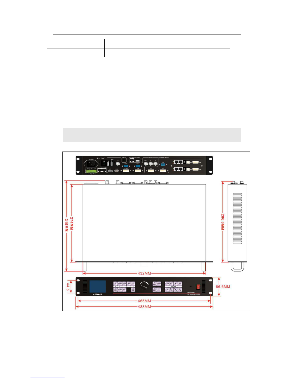
3.5 Product dimensions
Product Size
483(L) x 274(W) x 66.6(H)mm
Weight
G.W.:5.7 Kg, N.W.:4.2Kg

LVP615U
使用说明
13
RS232 cable order:

LVP615U
使用说明
14
Chapter 4 Front panel and remote control instructions
LVP615U supports front panel button, remote control, RS232 and LAN
control. Same printing on remote control buttons and front panel
buttons,same button functions. The instructions are as below.
4.1 Front panel buttons and remote control schematic
124
3
5
8
7
6
9
10
11

LVP615U
使用说明
15
1
4.1.1Input signal selection buttons
( , , , , , , , , ):select the
input signal.
4.1.2 Setup buttons( , , , , ), Set the output
image parameters.
4.1.3 VGA auto adjustment button ( )automatically adjust the
VGA input signal.
4.1.4 Switching time setup button
( ):
select seamless switching
time including 0 second (cut), 0.5 second,1.0 second and 1.5 second
( fade in fade out) and blend switching function.
5
4
6
The buttons on remote
control have the same
functions as the relative
buttons on front panel.
3
9

LVP615U
使用说明
16
4.1.5 PC signal bypass output ( ):Switch between part and full
display of PC signal. The indicator shows the current state of the input
signal.
4.1.6 PIP/PBP keys
( , , , ):
:PIP/PBP turn on/ off button. When the indicator is on, press
input signal selection to choose different group input or current input itself
as the PIP signal.
, , :Switch PIP/PBP model.
4.1.7 Mosaic button
( )
Turn on /off mosaic function. The
indicator shows the current state of mosaic.
4.1.8 Freeze button
( )
turn on / off freeze function.
4.1.9 Brightness adjustment button
( , )
adjust output
brightness level under user operation station.
4.1.10 remote control sensor: built- in infrared receiver.
4.1.11 remote launch window: built-in infrared transmitter.

LVP615U
使用说明
17
4.2 Remote control operation instructions
4.2.1 Open the battery compartment on the back of the remote control,
make sure the battery effective contact
4.2.2 Please aim remote control to the sensor area of LVP615U, if
there is obstacle between them, LVP615U may not receive
command.
4.2.3 To make sure remote control has a good performance. If found
improper operation, please replace new battery immediately.
4.3.3 Batteries shall not be exposed to, such as sunlight, fire or
the like overheated environment.
Chapter 5 Basic user instructions
After LVP615U boot, it enters the operation status of last shut-down including
signal switching status, PIP/POP (or Text overlay) status and mosaic status.
Among them, PIP/PBP( or text overlay) status and mosaic status can only
realize relative functions and cannot do other operation. Other relative
operations are available under signal switching status. We illustrate the
common operations as below.

LVP615U
使用说明
18
5.1 Input signals selection
LVP615U supports two signal switching methods including“One key
switching”and“Pre.+Take switching”. The switching method can be set in
user setup menu “2.6 switch mode”. “One key switch” is default method.
One key switch to new input signal through input signal selection buttons.;
“Pre.+Take switch” only available for seamless switching. Press input buttons
to preselect first. Then press Take button to switch from current input signal to
preselected signal.

LVP615U
使用说明
19
Input signal selection as follows
:
Buttons
Description
1* Composite video signal input (PAL/ NTSC)
1* Composite video (PAL/ NTSC) or analog
component video input
2 * PC analog signal input
1*DVI digital signal input
1 * HDMI digital signal input
1* DisplayPort digital signal input
*
1* extended signal input
Note:(1) YPbPr and V2 share the same port. If need,configure
the port to YPbPr in setup menu.
5.1.1 One key switch
LCD screen display as below:

LVP615U
使用说明
20
Input: HDMI
In Status: 1080p_60Hz
-------------------------------------Output Size: 1920x1080
Output Start: (0,0)
-------------------------------------Switch Mode: One Key SW.
Switch Time: 1.5 Sec
After select input signal, The first line on the LCD display the
current input signal. Like:“ Input:HDMI ” 。The second line on the
LCD display the signal status.If no active input, display” No input’.
Meanwhile,the corresponding indicator flicker. Led screen is black.
If active input, display input signal format Like:“ 1080p_60Hz ”
。
5.1.2 Pre.+Take switch
LCD screen display as below:
LVP615U
使用说明
21
Curr. Input: HDMI
Curr. In Status: 1080p_60Hz
Pre. Input: V1
Pre. In Status: PAL
-------------------------------------Output Size: 1920x1080
Output Start: (0,0)
Switch Mode: Pre.+Take SW.
Switch Time: 1.5 Sec
Switching signal method: press input button to preselect first, LCD screen
displays the current input status and preselect input status. Then press Take
button to switch current input to preselect input. After the completion of
switching, preselect signal become the current input signal. The status of the
preselect signal indicator: when the signal is valid, the indicator flicker rapidly.
when the signal is invalid, the indicator flicker slowly.
Note:Pre.+Take switch only available for seamless switching. LVP615U
supports seamless switching between any two different input groups as follow.
Same group does not support seamless switching. For example, current input
is V1( V1 in group A). Then, preselect signal is only from B,C,D group. Signal
group as follow.
:
ABC
D
V1、V2
VGA1、
VGA2
DVI、
HDMI、DP
EXT
5.1.3 Switching time setting(C/ F
)

LVP615U
使用说明
22
In the signal switching status, press C/F button continually can change the
current seamless switching transition time. LVP615U can achieve seamless
switching between any two different input groups of four input groups.
Switching effect includes seamless switching (0s), Fade in/ Fade out (o.5s 1s
1.5s) and blend switching.
Seamless switching(Cut):On the LCD“Switch time” is 0s. LVP615U default
switching is CUT.
Fade in fade out(Fade):On the LCD“Switch time”is 0.5s、1.0s or 1.5s. In this
mode, different group signals support fade in fade out switching.
Blend switching:at this moment, on the LCD, current input is the main input.
Select different group input signal as blend signal. The main input will overlay
in the blend signal. Press blend signal or main signal button again. Then switch
to selected signal. The whole process is fade in fade out effect.
Main Input: HDMI
Main In Status: 1080p_60Hz
Blend Input: V1
Blend In Status: PAL
-------------------------------------Output size: 1920x1080
Output start: (0,0)
--------------------------------------
Note:1. YPbPr does not support seamless switching, fade in
fade out or blend switching. Switching between any signal and
YPbPr signal will cause black led screen.
2. Blend switching is only for signal switching. For other
operations, press C/F to exit the blend switching state.

LVP615U
使用说明
23
5.2 PIP/PBP operation
LVP615U allows to insert PIP window on the current display signal.
That is dual image display function(PIP/PBP)。PIP signal can be any
input signal from other input groups or current input signal itself.
(
signal group refer to page 19signal group list)Dual image size can
be preset 3 modes.The detailed operation method is as follow:
Enter PIP/PBP mode: press On/Off button,the indicator will
be on. LVP615U enters PIP/PBP mode. Then press input signal button
to select PIP signal. At the same time, LCD will display main input and
pip input status and size.(as shown below
)
Main Input: HDMI
Main In Status: 1080p_60Hz
PIP Input: V1
PIP In Status: PAL
-------------------------------------Main Output Size: 1920x1080
Main Output Start: (0,0)
PIP Output Size: 640x320
PIP Output Start: (16,16)
Select PIP input signal:In PIP mode,press button to select
corresponding signal. Then this signal is configured as PIP input.
Select Main input signal: Press On/Off button to close PIP
mode.,Press button to select corresponding signal as main input
signal. Then press On/Off button to enter PIP mode to select pip
signal again.

LVP615U
使用说明
24
Switch PIP/PBP mode:When PIP/PBP is on,press buttons M1、
M2、M3 directly to select display mode fast.
5.3 Mosaic operation
Multiple units LVP615U cascading can drive huge resolution LED screen.
Only when the current input is DVI, press Mosaic button and the indicator is
on. LVP615U enters to Mosaic operation. Press the button
again and the indicator is off, LVP615U exits Mosaic.
Mosaic Input: DVI
In Status: 1080p_60Hz
Input Image Size: 960x540
Input Image Start: (0,0)
-------------------------------------Mosaic out size: 1920x1080
Mosaic out start: (0,0)
Mosaic PIP: off
-------------------------------------Device ID: 1
Note:
5.3.1 In mosaic mode, PIP display is available.
5.3.2 In following conditions , LVP615U cannot enter mosaic
status.
(1)The input signal selected is not DVI;
(2)
Bypass is on
;
(3)The resolution of DVI input signal is different from the
output resolution of processor.
LVP615U
使用说明
25
5.4 Other basic user operation
5.4.1 Brightness selection(Brt+,Brt-)
LVP615U supports 64 level or 100 level brightness selection.
According to“8.5 bright level” selection,adjustment range has two
kinds:0~64 or 0-100. Factory default is 0-64。To make sure of full
gray scale of output image, it always set as 64(0-100 default value is
50) !
button
description
BRT-
Reduce LVP615U output brightness,the lowest
is 0.
BRT+
Increase LVP615U output brightness, the
highest is 64 or 100.
5.4.2 VGA input auto adjustment (Auto)
When LVP615U is in one key switch status and current valid
input signal is VGA, press Auto button to adjust VGA input signal
sampling parameters. Then the VGA output image can be clear and
full.
This operation is normally performed when a new VGA source
is connected. Auto adjustment time is depend on the signal status.
LVP615U
使用说明
26
Normally it’s less than 1 second. Sometimes it’s necessary to
perform several times until the output image is clear, full and stable.
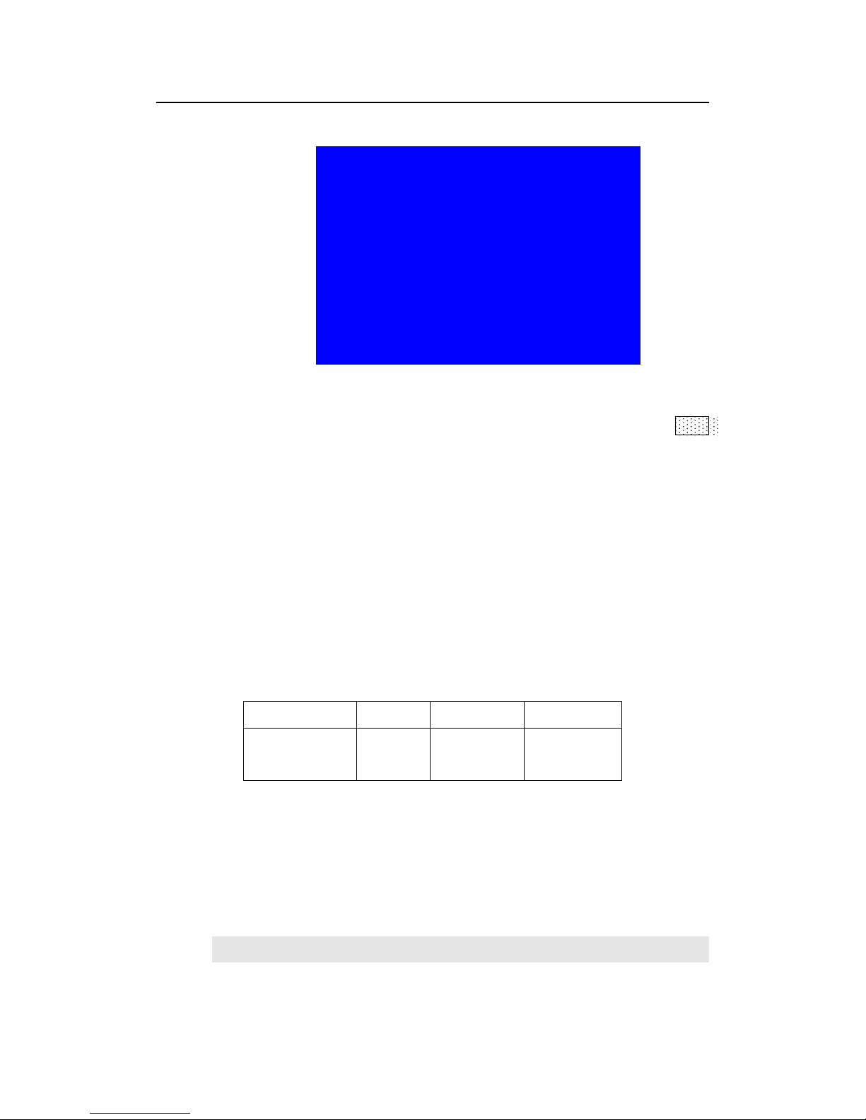
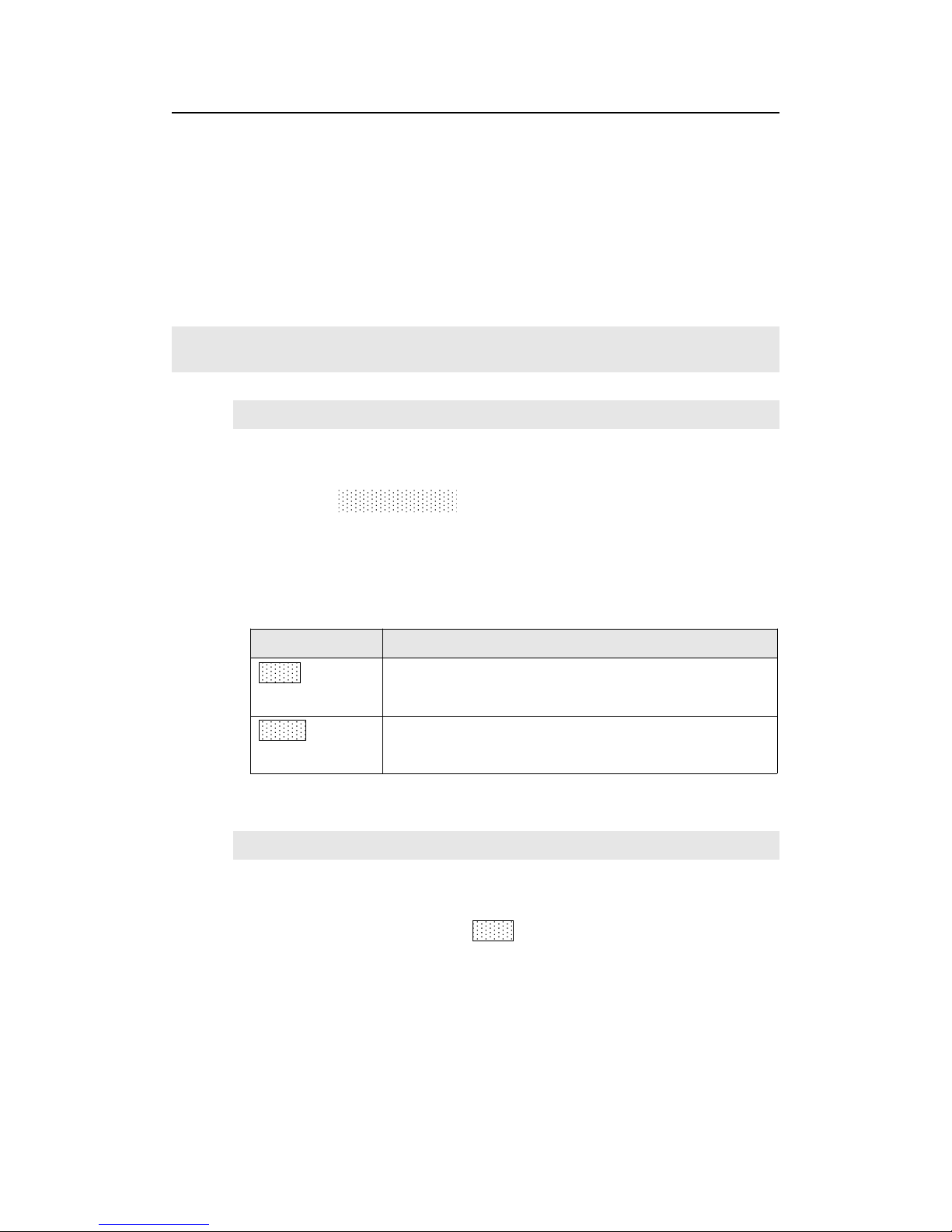
5.4.3 Full/ part display(Bypass)
In signal switching status, press Bypass button to switch full
and part display.
This function only works when current signal is PC input signal
(VGA1/ VGA2/ DVI /HDMI /DP). Fixed other signals to Full mode.
state
description
Full
Full display,the input image is compressed and fully
displayed on the led screen and the indicator is off.
Part
Part display, the input image is not compressed.Only a
part of it can be displayed on the screen and the indicator
is on.
Note:When the width and height of input image are lower than the
LED screen real width or height value. Part display is invalid.
5.4.4 Text overlay
LVP615U allows for overlapping text, logo or flash on the current
image. The operation is as below.
When the current input display properly, enter setup
menu“3.Text overlay” , set ”3.1text overlay” on , then select text
source.Text can be produced by PowerPoint and other office software.

LVP615U
使用说明
27
5.4.5 Image freeze (Freeze)
Press Freeze button and the indicator is on, the current image is
frozen. Press Freeze button again or switch to another signal to exit
Freeze status.
5.4.6 Device information view (OK)
In signal switching status, press OK to check the LVP615U current
setting and information.
System info
-------------------------------------model: LVP615U
version: V0.0.8/V0.0.8
IP: 192.168.1.8
Mask: 255.255.255.0
Gate: 192.168.1.1
MAC: 76-64-77-00-00-00
Device ID: 1
Chapter 6: Setup menu instructions
Setup menu is to set the entire processor. There are 9 section including
output image 、 input image 、 text overlay 、 image quality 、 audio 、
communication、language、advance、PIP/PBP、mosaic.
LVP615U
使用说明
28
setup
--------------------------------------
1. Out Image >>
2. Input Video Signal >>
3. Text Overlay >>
4. Color&Brightness,etc >>
5. Audio >>
6. Communication >>
7. 语言/Language >>
8. Advance >>
After the system starts , Press Setup to enter the setup menu.Then
press↑,↓ button to select the corresponding menu item to be set. Press OK
button to enter and return back upper level menu. The following is a
detailed description of each menu function
:
6.1 Output image setting
Press Setup to enter setup menu. Press ↑,↓ button to select“1.Out

LVP615U
使用说明
29
image” item.Then press OK button to enter the following image“1.Out
image” item.
1.Out Image
--------------------------------------
1.1 Resolution 1920x1080_60
1.2 Out Width 1920
1.3 Out Height 1080
1.4 Out H_Start 0
1.5 Out V_Start 0
1.6 Test Pattern off
6.1.1 Set output format
LVP615U can output image from the VGA OUT and 2 DVI OUT.
There are 16 fixed output format and custom output format.(refer to
page 9specifications) . Users can select fixed output format not less
that the LED screen resolution or select custom output format which
can realize pixel to pixel display in concert with 2.1 .1 custom DVI
EDID.
Operation steps:
Press ↓to select “1.1 Resolution” item. Rotate knob to select
suitable output format,like“1280×1024_60”,Press OK button, the
screen will display confirmation menu. Press OK button again to
confirm the output format. The device will restart automatically.

LVP615U
使用说明
30
tips
--------------------------------------
Data will reset
Press <OK> to reset
Press <return> to cancel
Note: to custom output format,after selection,need further set
1.1.1 custom width、1.1.2 custom height and 1.1.3 custom V frequency.
Press ↓ button to 1.1.4 Apply,Press “OK”to make parameters
effective.
1.1 Custom Resolution
--------------------------------------
1.1.1 Cus. Width 1920
1.1.2 Cus. Height 1002
1.1.3 Cus. V Freq. 60
1.1.4 Apply OK To Apply

LVP615U
使用说明
31
6.1.2 Set output image parameters
LED screen real resolution can be arbitrary. So we need set
LVP615U to output the same image as the led screen. Then the LED
screen can display whole image.
(0,0)
Out hori start_LL
Out_hori_width
Our vert_start
Out vert height
LED screen
LVP615U output resolution = 1920×1080
LVP615U out image area
1920
1080
As shown in the above picture: the size and location of output
image of LVP615U can be defined in 4 parameters:
Item NO.
Item name
1.2
Out_hori_width
1.3
Out_vert_height
1.4
Out_hori_start
1.5
Out_vert_start
Note: current set parameters can be changed by rotating knob.
knob rotating speed can decide the step value. Press“OK”button to
save the set parameters.

LVP615U
使用说明
32
6.1.3 Test pattern
LVP615U can generate 36test patterns for LED screen testing.
If this item value is “off”, turn off Test pattern. Select other number
and confirm.Then one corresponding test pattern of 36 pcs will be
selected.
Operation steps
:
Press ↓ button to select“1.6 Test pattern” item,then rotate knob
to select suitable test pattern number and press ”OK” to apply the test
pattern.
--------------------------------------
1.1 Resolution 1920x1080_60
1.2 Out Width 1920
1.3 Out Heith 1080
1.4 Out H_Start 0
1.5 Out V_Start 0
1.6 Test pattern 0 - >5
Note: The current signal must connect valid input. Then the test
pattern has output. Otherwise no output.

LVP615U
使用说明
33
6.2 Input video signal setting
Press Setup button to enter setup menu. Press↓ button to select 2.
Input video signal and press OK to enter this item.
2.Input video signal
--------------------------------------
2.1 DVI EDID 1280x1024_60
2.2 V1/V2 backup off
2.3 VGA1/VGA2 backup off
2.4 HDMI/DVI backup off
2.5 V2 or YPbPr V2
2.6 Switch mode one key switch
6.2.1 DVI EDID
LVP615U supports custom DVI EDID. In concert with “custom
output format”, LVP615U can realize DVI input image and output
image pixel to pixel display. LVP615U supports 16 fixed DVI EDID and
custom EDID. Normally the parameters setting should be consistent
with“custom output format”(refer to page28 ).
Operation steps:In the menu 2.1 DVI EDID,rotate knob to
select suitable resolution and press OK to save data. After save data,
need press OK to enter“2.1 custom DVI EDID” menu to set
2.1.1custom width、2.1.2custom height and 2.1.3 custom V frequency
and press ↓ to enter APPLY and press “OK” to make parameters
effective.

LVP615U
使用说明
34
2.1custom DVI EDID
--------------------------------------
2.1.1 Cus. width 1920
2.1.2 Cus. height 1002
2.1.3 Cus. V Freq. 60
2.1.4 Apply OK to apply
6.2.2 Hot spare setting
LVP615U supports hot spare of input signals. When the current
input signal is lost. LVP615U will switch to the spare signal
automatically to avoid image interruption caused by the fault of signal
source.
2.Input video signal
--------------------------------------
2.1 DVI EDID 1280x1024_60
2.2 V1/V2 backup off
2.3 VGA1/VGA2 backup off
2.4 HDMI/DVI backup off
2.5 V2 or YPbPr V2
2.6 switch mode one key switch
As shown in the above table ,if ”2.2 V1/V2 backup on”, if V1
signal is lost, processor will switch to V2 automatically.
6.2.3 V2 or YPbPr selection
V2 and YPbPr of LVP615U share the same port and button. Need
configure. Default input is V2. If need YPbPr input, then need set this

LVP615U
使用说明
35
port to YPbPr.
Operation steps
:
In the menu of 2.5 V2 or YPbPr,rotate knob to select needed
parameters and press “OK” to make them effective.
6.2.4 Signal switch mode
Press Setup to enter setup menu,press ↓ to select “2. Input video
signal”,Then press OK to enter“2.input video signal ”,and press ↓ to
select signal switch mode“one key switch ”or Pre.+Take
switch ”,Press OK to apply.
2.Input video signal
--------------------------------------
2.1 DVI EDID 1280x1024_60
2.2 V1/V2 backup off
2.3 VGA1/VGA2 backup off
2.4 HDMI/DVI backup off
2.5 V2 or YPbPr V2
2.6 switch mode Pre.+Take SW. ?

LVP615U
使用说明
36
6.3 Text overlay setting
3.Text overlay
--------------------------------------
3.1 Text overlay off
3.2 Text source ?
3.3 Text mode < threshold
3.4 Threshold R 8
3.5 Threshold G 4
3.6 Threshold B 8
6.3.1 Text overlay operation
In the current input signal
,
press Setup and press↓ to
select”3.text overlay” , Press OK to enter , in the menu“3.1text
overlay ” rotate knob to switch it on. Then press ↓ to enter”3.2text
source ” menu to rotate Knob to select text input signal. Text
overlay is on. If need turn it off, enter 3.1 text overlay and switch it
off.
6.3.2 Text overlay parameters setting
3.1Text mode:LVP615U can custom text mode < threshold
or > threshold. < threshold means text signal image which is less
than the current threshold value will overlay on the current signal.
The bigger part will be automatically filtered out. > threshold means

LVP615U
使用说明
37
text signal image which is bigger than the current signal will overlay
on the current signal.
Threshold R /G/B:This is used to set three thresholds
subtitles red, green and blue respectively for a particular value
between 0 to 248.
The following is the text overlay example. Text file is made by
Powerpoint. Parameters are as follow:
Main picture text text overlay
3.3
Text mode
<threshold
3.4
Threshold R
248
3.5
Threshold G
248
3.6
Threshold B
248

LVP615U
使用说明
38
6.4 Color& Brightness,etc.
4.Color&Brightness Default
--------------------------------------
4.1 Input color 50
V1=50 V2=50
HDMI=50 DVI=50
DP=50 EXT=50
V1=50
All=50
4.2 Sharpness normal
4.Color&Brightness Default
--------------------------------------
4.3 Brightness 50 50
LVP615U supports custom color,sharpness and brightness setting.
List as follow:
Item name
Definition
4.1 color
Adjustment range:0~100, default 50

LVP615U
使用说明
39
4.2 sharpness
Normal or sharp,default : normal.
4.3 brightness
According to “8.5 brightness level” setting,
adjustment range includes 0-64 or 0-100.
The factory default of adjustment range is
0-64 and default is 64.“Brightness level” can
be set in factory setting.
Note:1). To make sure of full gray scale of output image, these
output parameters are set as default.
2).Color parameters are invalid for RGB format DP, DVI and
HDMI. VGA is RGB format. So setting is not available.
6.5 audio setting
5.Audio
--------------------------------------
5.1 AD1 Config V1
5.2 AD2 Config V2
LVP615U supports 4 channels of stereo audio input signals. Three
of them are HDMI and DP audio. The other two AD1 and AD2 are
external input. Audio input signals for AD1 and AD 2 can be configured
to match the video input signals correspondingly and switching
between AD1 and AD2 is synchronous to that between the video
inputs.
Operation way
:
Press ↓ button to select 5.1 AD1 config or 5.2 AD2 config menu,
Rotate knob to select corresponding input signals and press OK to

LVP615U
使用说明
40
save.
If HDMI(or DP)is configured as external audio input, processor
will select external audio input signal when switching to HDMI
(
or
DP Otherwise, it will select HDMI(or DP)itself audio as input.
1、 6.6 Communication
6.Communication
--------------------------------------
6.1 IP: 192.168.1.8
6.2 mask: 255.255.255.0
6.3 gate: 192.168.1.1
6.4 Mac: 76:64:77:00:00:00
--------------------------------------
6.5 device ID 1
LVP615U can be remotely controlled via Ethernet. Communication
setting menu is used to set network parameters including IP address,
mask, gate, MAC and number the multiple LVP615U under the same IP.
The following is the method of operation:
In the menu of “6. Communication”,press ↓ to enter the setting,

LVP615U
使用说明
41
rotate knob to select parameters and press OK to save. The LCD screen
will give tips to restart the system and do according to the prompt.
6.7 Language setting
LVP615U supports Chinese and English language.Rotate knob to
select one and press OK to save.
7. Language
--------------------------------------
7.1 语言 Language Chinese

LVP615U
使用说明
42
2、 6.8 Advance setting
8.advance default
--------------------------------------
8.1 ADC calibration OK to apply
8.2 Bias 50 50
8.3 EXT.Input model EXT.VIDEO
8.4 De-Interlace off
8.5 Bright level 0-64
8.6 DVI hotplug off
8.7 Wifi reset OK to apply
8.8 Device reset OK to apply
6.8.1 ADC Calibration
“8.1 ADC Calibration” is used to calibrate the white balance of
analog signals to avoid color cast or extreme darkness problem.
This function is only available for non ext. Input VGA,CVBS and

LVP615U
使用说明
43
YPbPr. The operation way is as follow:
In the current available Analog signals, enter“8.1 ADC
calibration” and press OK to start to calibrate.
Note:Processors finished white balance calibration before
leaving factory. Please use this item carefully.
6.8.2 Bias
To reduce noise of low gray scale images, LED display system
normally will remove the low gray scale part from input signals. But
this will also bring information loss of images, especially dark
images like night scenes.
LVP615U can adjust“ 8.2 Bias ” parameters to adjust. The
value range is :0— 100. In the case dark image information lost,
adding this value will bring back the lost information and fully
display the image on LED display.
Note: to make sure of full gray scale of output image, the
default value is 50.
6.8.3 EXT. Input Model
The option is used to configure extended module after replacing it,
to make sure the module can work normally. Operation is as below:
Entering “8.3 EXT. Input Model” option, rotate knob to select
relative option, press OK button to save. The setting will be active
after restarting.
6.8.4 De-Interlace

LVP615U
使用说明
44
This option is used to remove trembles, which might happen when
inputs are CVBS/S-Video/HDMI/SDI signals interlace signals (e.g.:
1080i) and used as PIP.
Operation is as below:
Enter “8.4 De-Interlace”, rotate knob to select “On”, press “OK” button
to make setting active.
6.8.5 Brightness Level
According to different demands, user can select relative “Bright Level”.
“8.8 Device Reset” will not change the parameter of “bright level”. When
multiple units doing cascading splice, all units must be same “bright level”.
Operation is as below:
Enter “8.5 Bright Level”, rotate knob to select “0-64” or “0-100”, and press “OK”
button to confirm the setup.
6.8.6 DVI hotplug
“DVI hot plug signal” is sent by processor to graphic card or other signal source
devices, as a gist to let the signal source device whether outputs DVI signal
source or not. A few PC when use some software play video on extended
desktop, the “hot plug signal” to the device may cause the player out of order
on extended desktop. If this happens, please enter setup menu “8.6 DVI
Hotplug” to turn this function off.
Bright
level
Description
0-64
0 is minimum brightness, 64 is default standard
brightness.
0-100
Allow higher brightness value: 0 is minimum and 50 is
default value.

LVP615U
使用说明
45
1) 6.8.7 Wifi reset
The menu item is used for resetting LVP615U’s Wifi module parameter.
Operations as below:
Enter “8.7 Wifi Reset”, press “OK” button, there is one information on
LCD screen to remind you data will reset. Press OK button to apply.
LVP615U starts to reset..
8) Device Reset
The menu is used to initialize LVP615U. Operation as below:
Enter “8.8 Device Reset” and press OK button, there is one information
on LCD screen to remind you data will reset. Press OK to apply.
LVP615U
will reset and restart.

LVP615U
使用说明
46
6.9 PIP/PBP setting
D.PIP/PBP Mode=M1
--------------------------------------
D.1 PIP Width 640
D.2 PIP Height 320
D.3 PIP H_Start 16
D.4 PIP V_Start 16
D.5 MAIN Width 1920
D.6 MAIN height 1080
D.7 MAIN H_Start 0
D.8 MAIN V_Start 0
The setup option is used to set LVP615U’s three user defined PIP/PBP mode.
Operation as below:
When LVP615U’s PIP/PBP status is open (the indicator light on “On/Off” button
is lit up), press Setup button, LVP615U enters “D. PIP/PBP” menu. Then press

LVP615U
使用说明
47
mode button (M1, M2 or M3) to select a mode to save parameters, press ↓ to
select parameter option needed to adjust. For example “D.1 Main Width”,
rotate knob to change parameter, press OK button to save.
(0,0)
PIP H_start
PIP Width
PIP V_Start
PIP height
Main out image
LVP615U output resolution = 1920
×
1080
1920
1080
Pip out image
Main V_start
Main height
Main width
main H_start
6.10 Mosaic setting
E.Mosaic(Video Wall App)
-------------------------------------E.1 LED Total Width 3840
E.2 LED Total Height 2160
E.3 Unit Width 1920
E.4 Unit Height 1080
E.5 Unit H_Start 0
E.6 Unit V_Start 0
E.7 Sync.Mosaic ON
E.8 Auto Calculation OK To Apply

LVP615U
使用说明
48
E.Mosaic(Video Wall App)
-------------------------------------E.9 In Width 960 960
E.10 In Height 540 540
E.11 In H_Start 0 0
E.12 In V_Start 0 0
E.13 Out Width 1920 1920
E.14 Out Height 1080 1080
E.15 Out H_Start 0 0
E.16 Out V_Start 0 0
LVP615U can maximally output 2304*1152 or customized resolution with
maximal horizontal 3840 pixels or vertical 1920 pixel. To drive such high
definition, LED display requires two transmission cards in cascade, so
LVP615U provides 2 positions for two built-in transmission cards.
If the actual definition of LED display exceeds the maximum output definition
of LVP615U, you may divide the whole LED screen into pieces of smaller LED
screens, then put them together in Mosaic manner by connecting multiple sets
of LVP615U in parallel to integrate the smaller pieces of LED screens into a
large LED display.
With frame synchronization technology, LVP615U solves the problems of
misplacement and delay of output image existing in ultra-large LED mosaic,
being able to provide real-time, clear and fluent display effects.
LVP615U supports multiple units cascading splicing. By this way, smaller
pieces of LED screens can be integrated into a large display. For example, if
the output definition of LVP615U is set as 1920×1080, and we put 2 sets of
LVP605 together horizontally in parallel, it will be able to connect any LED
display of up to 3840×1080 pixels.
There are 16 setup options in splicing setup menu, setup options 1-8 is
automatic splicing menu, 9-16 is fine adjustment, automatic setup menu is
used to input splicing screen’s parameters, in fine adjustment menu option
adjust parameters for outputting full picture.
Adjustment options
Descriptions
E.1 LED total width
The whole width and
height of LED screen
E.2 LED total height
E.3 unit width
The LED screen
resolution and position
E.4 unit height

LVP615U
使用说明
49
Automa
tic
splicing
menu
compared with the whole
spicing screen driven by
this unit of LVP615U
E.5 unit horizontal
start
E.6 unit vertical start
E.7 sync. splicing
ON or OFF of the sync
splicing
E.8 automatic
splicing
Application of automatic
splicing parameters
Manual
setup
menu
E.9 in width
The size and location of
DVI input image the
current unit crops
E.10 in height
E.11 in H-start
E.12 in V-start
E.13 out width
Output parameters of
LVP615U, it is as same
as the menu 1. Output
image
E.14 out height
E.15 out H-start
E.16 out V-start
Enter adjustment setup: under splicing mode (Mosaic indicator lit up), by
pressing “Setup” button, LVP615U enters splicing adjustment setup menu “E.
Mosaic”
Return to upper level setup menu: under the mode of adjustment setup,
press “ ” button, LVP615U exits adjustment setup.
Note: when use multiple LVP615U cascading splicing, to make sure the output
image have uniformity, every unit’s parameters of 4.3 brightness, 4.1 inpu color,
4.2 sharpness and 8.2 bias must be same.
Operation is as below:
When the input signal of LVP615U is DVI format and the splicing mode is open
(Mosaic indicator lit up), press Setup, LVP615U enters splicing menu. Press
↓button to select setup option needed to adjust, rotate knob to change
parameter, press OK button to save.
Operation is as below :
In the menus E.1~E.2, input parameters of whole splicing screen;
In the menus E.3~E.4,input the size and location (relative to whole splicing
screen) of LED screen the LVP615U drives;
In the menu E.7 sync. Mosaic menu, select to turn the function on or off;

LVP615U
使用说明
50
In the menu E.8 auto Calculation, press OK, LVP615U starts to mosaic
automatically;
Observing image splicing effect. If any problem, enter fine adjustment menu
option E.9~E.16 to adjust image.
Below is a 2×2 mosaic example using 4 sets of LVP615U, telling us how to use
multi-units cascade of LVP615U and what we should pay attention to.
The definition of the LED screen is 3456×1920, we can divide it into the four
small pieces of LED of 1728×960 pixels as shown in figure below, each piece
of small LED screen is driven by a unit of LVP615U. With total 4 sets of
LVP615U, the 3456×1920 pixels LED screen is able to display a full picture.
#1(1728×960)
#2(1728×960)
#3(1728×960)
#4(1728×960)
Below is the system topological diagram:

LVP615U
使用说明
51
LOOP
LOOP
DVI
LOOP
LVP615U#0
#1
#2
#4
#3
Input signals
LVP615U#
LVP615U#
LVP615U#
LVP615U#
System Topology
3456
1920
As above diagram shows, all input signals are connected to and switched by
#0 LVP615U. The 2 same DVI outputs of #0 LVP615U are connect to #1
LVP615U and #2 LVP615U. Then DVI loop to #3 and #4.
After that, the output signal of #0 LVP615U is cropped and scale up in #1
LVP615U, #2 LVP615U, #3 LVP615U and #4 LVP615U.
Finally the image that they output will be finally displayed as a whole picture on
4 pieces of LED screens.
The parameters of the 4 units of LVP615U are as below:
Setup options
Parameter setups of processor
#1#2#3
#4
E.1 LED total width
3456
E.2 LED total height
1920
E.4 Unit width
1728
1728
1728
1728
E.5 Unit height
960
960
960
960
E.6 Unit horizontal
start
0
1728
0
1728

LVP615U
使用说明
52
E.7 Unit vertical
start
00960
960
E.8 Synchronization
splicing
ON
In order to ensure all output images are synchronous to each other, please
note the following settings:
1. The input signals can be only DVI signals, and if the processor is in mosaic
mode, it will be unable to switch input signals;
2. All the 5 processors must be set the same output resolution.

LVP615U
使用说明
53
Chapter 7 Remote control instructions
LVP615U opens RS232 control protocol supporting PC, Android or IOS
intelligent remote control terminal. Here we instruct the hardware connection
and software operation as below.
7.1 Hardware communication
LVP615U remote control ports include RS232, USB, Wired network and Wifi
control. As below we illustrate hardware communication connection and setup
respectively.
1
342
LVP615U Remote communication
ports
1 :RS232
2 :USB
3 :LAN

LVP615U
使用说明
54
7.1.1 RS232 and USB
RS232 is common port for remote control. When use RS232 control, we only
need to use an RS232 cable to connect PC to processor’s RS232 port, then
we can use software to remote control processor. When PC does not have
RS232 port, USB control method can be used.
PC
LVP615U
RS232 or USB

LVP615U
使用说明
55
7.1.2 Wired network
LVP615U built-in network convert RS232 module, after wired network
connecting LAN and setting relative network configuration parameters (refer
user manual page 38 “6. Communication ”), LVP615U has been a work station
in the local area network. So another terminal device in the local area network
can control the LVP615U through software. As the picture below, through
software, anyone of terminal (work station) in the local area network can
control the LVP615U in the local area network by remote method.
router
Work station2
Network cable
Network cable
Work station1
LVP615U
WIFI

LVP615U
使用说明
56
7.1.3 WIFI connection
LVP615U is built in WIFI module. Through this module, user can achieve WIFI
remote control of LVP615U. The module supports 2 WIFI connection methods:
First., Wireless Router, another wireless device connects the module directly
and control.
Second, Through WIFI connect wireless Router and become a work station in
the local area network, so another terminal device in the local area network
through software to control LVP615U by remote method, the control method is
similar through LAN port connecting.
Here are relative setup and instruction about LVP615U WIFI module and how
to realize the 2 control methods.
NOTICE: When using WIFI connection, WIFI ANTENNA must be installed.

LVP615U
使用说明
57
7.1.3 WIFI connection
Using laptop with wireless network, open network and share center,
search and connect the wireless network named LVP615U, the default WIFI
password is 88888888
Configuring network be automatically obtain IP address and DNS server
address, show as the picture below:

LVP615U
使用说明
58
Configuring network be automatically obtain IP address and DNS server
address, show as the picture below:

LVP615U
使用说明
59
Note: if can’t connect, entering setup menu “8.7Wifi reset” to reset WIFI
module (refer user manual page 48), then restart and connect.
7.1.4 Wireless Module Configuration
1) Running wireless scan configuration software “LVP615U WIFI
Config
Tool.exe”, the application software is as below.

LVP615U
使用说明
60
2) Click “Scan” to search LVP615U in the local area network,
after searching module the information display as below.

LVP615U
使用说明
61
(3) In scan list click relative WIFI module, when appear dialog box, type in user
name (default name is admin) and password (default password is admin),
software will remind “module identify successfully” and “obtain configuration
parameter successfully”, meanwhile software interface will display relative
information.
( 4 ) Now you can configure module. Configuration options include Mode
Setting, AP Setting, STA Setting, Serial Port Parameter Setting , Socket Setting
and Advanced setup. See the configuration method step by step below:
Notice: after configuring every step, you need to click save button to save
configuration parameter. All modified parameters will be valid after module
restarting.
a. Mode Setting
This step mainly sets the Mode and Consumption Level of module.

LVP615U
使用说明
62
Normally we set the consumption being “Full”, mode description as the table
below. Select the level according to your need. After
modifying configuration click “save” button to save.
Work Mode
Description
AP
Establish a encrypted wireless network,
similar to a wireless router. Mainly used
to reset module, or control WIFI in the
status of no local area network.
(Recommended)
STA
Make the LVP615U as a work station,
configure and join a wireless network. It
can be realized by typing in router
name and password.
b. AP Setting and STA Setting
After selecting the mode, we need to configure specific
parameters for the mode. See as below:

LVP615U
使用说明
63
AP setting

LVP615U
使用说明
64
Click search key to find the around wireless network.
STA setting
Notice: Better use manual method instead of automatic method to avoid
disconnection due to IP address changes.

LVP615U
使用说明
65
c. Serial Port Parameter Setting
This step is for setting basic parameters of serial port, after
modifying configuration, click “save” button to save change. As the picture
below shows, the boardrate should be 9600.
d. Socket Setting
This step is for Setting basic parameter of Socket. Single or
Double Socket are supported, After setting configuration, click “Save” button to
save. Please notice that the local port number of Socket A should be same
when configuring the PC software.

LVP615U
使用说明
66
E. A super manage
Super manage includes modifying user name and
password of module (Identification information), name and group name of
module, reset module and reset to default, Please set according to needs. See
the picture below:

LVP615U
使用说明
67
7.2 PC control software instructions
LVP615U’s control software used to control LED HD video processor LVP615U.
Through the software, we can realize:
Selecting input signal switch by seamless switching or fade in fade
out mode
3 user defined modes of double picture display or test overlay
Turn on or off Bypass, Freeze and Mosaic functions
Specific parameters of LVP615U setting
Timing control function: set time for switching or select input signals
Multi units cascading splicing function

LVP615U
使用说明
68
7.2.1 Control method
As illustrated above, the PC remote control of LVP615U can
realize connection by RS232, USB, LAN or WIFI. After connecting and
needed configuration, we can run the control software: “LVP615U
Control Software.exe”
1、 Introduction of Software Interface
Double click the software, the software interface shows as below:

LVP615U
使用说明
69
As shown above, there are 9 main parts of the software:
1) Communication Setting
2) Language Setting
3) Signal Switch
4) Function and Mode Selection
5) Information
6) Timing Control Setting
7) Output Parameters Setting(Screen Setting)
8) Multi Units Cascading Splicing Setting(Quick Mosaic)
9) Output Resolution Setting
1)Communication Setup

LVP615U
使用说明
70
In communication setup, first select connection method being Serial or
network.
If select serial, need to select correct COM port. COM port number can be
checked in PC’s “device manager”, show as the picture below:
The device ID number you select must be as same as the LVP615U’s which
you need to controlled.
If select network connection, firstly must set the network connected being
correct, the relative setup about wired network prefer 6. Communication (user
manual page 46), wireless network setup refer user manual page 53. In IP
address and port number option type in correct setup, the default setup of
wired network and wifi AP mode refer the table as below.
connection
Default IP address
Default port
LAN
192.168.1.8
7
WIFI
192.168.7.1
25000
Click “connect” button, the software shows

LVP615U
使用说明
71
。
After the device connecting successfully, every function button in software inter face has
been activated. Information area on main interface displays reminder connecting
successfully.
Setting timer automatically start: to select whether the processor automatically
connect serial port and automatically open the timing control in next starting up.
2) Language setup
Software interface displays language selection, and the software supports two languages
Chinese and English.
(3)Signal select
The buttons of the signal area respectively represent the corresponding keys and status
indicators in the panel of the processor.
After the device is successfully connected, the software will read the input signal source
you currently selected and the blue indicator above it will turn on. If the blue indicator
illuminates normally, it means the input signal source you currently selected is valid;

LVP615U
使用说明
72
however, if the blue indicator blinks, it means there are no valid signal input.
AUTO
:
VGA automatically adjust button, only available for VGA1, VGA2 and EXT.VGA.
Switching effect selection, can select cut (seamless switching) and fade in / fade out (0.5s
1s 1.5s) switching.
Switching mode:
Default switching mode is one key switch, this moment press signal button, switch
input to relative signal;
If select pre + TAKE switching, the signal area become the style as below,
4) function and mode setup
The buttons in this area used for PIP, TEXT (Text Overlay), BYPASS, FREEZE, MOSAIC
PIP/PBP:PIP switch, used to open or close PIP mode, meanwhile the bright point
above the button indicates the mode open or not.
M1、 M2、 M3:PIP mode buttons, the blue bright point above the mode button shows
which mode you have selected.
TEXT:text overlay display switch, used open or close text overlay function; meanwhile
the bright point above the button indicates the function is open or not.
BYPASS:full and part display switch button, only available for PC signal VAG DVI HDMI
DP.
Freeze:Image freeze switch button, it is available when under signal switch mode.

LVP615U
使用说明
73
5) Information column
If operation is unsuccessfully, the information area will display the reason of failing.
6) Timing control setup
The Timer of the Control Software can switch the input signal source of LVP615U as per
the preset timer plan. The system provides four cycle timer modes, i.e.: Day, Week, Month,
Once.
Start timing:Start: open timing control function
Stop timing:stop timing control function
Timer<<: spread or shrink timing execution list on right side.
Click “Program” to enter timer setup menu, where you can view the timer plan you
already set, or add, modify, delete timer plans.

LVP615U
使用说明
74
Setting timing parameter
In user interface click Program, appear setup interface of timer, show as the picture below:
Show as the picture above, there are two types of plan:
(1) Cycle Plan
(2)Once plan
Cycle Plan is sub-divided into three types:
(1)
Day plan(timing in one day
)
(2)Weekly plan (timing in one week)
(3)
Monthly plan(timing in one month
)
User can select one type he desires
The plan items of Day Plan define hours, minutes, seconds;
Each week has 7 days, so the plan items of Week Plan define week day, hour, minute,
second;

LVP615U
使用说明
75
Each month has maximum 31 days, so the plan items of Month Plan define date, hours,
minutes, seconds;
The plan items of Once Plan define year, date, hours, minutes, seconds;
Cycle plan and once plan can work together.
For each type of plan, the plan items can be added, modified, deleted.
For example, the figure below shows how to add plan items to a day. Plan
Select the plan already added, then you can modify or delete it.

LVP615U
使用说明
76
7) Output date setup
In user main interface click Setup, appearing the setup interface of output parameter, in
the interface user can set output parameters of processor.
As shown in above figure, the button “Refresh” is used to update the information of
currently processing parameters after parameters configuration is finished. Any abnormal
of parameter will be reminded in info field.
The setting parameter in interface has zury background indicates the parameter is typing
in or aren’t saved, grey background indicates the parameter has been saved.

LVP615U
使用说明
77
Show as the picture
Screen output parameters include these parts as below:
(1) Image input/output parameters configuration and mosaic mode setup
The parameters of output windows should be configured to the actual pixels of the screen
to be driven.
Mosaic mode setup and input image parameters configuration apply to multi-machine
parallel mosaic only. The mosaic options are provided to set whether the processor adopts
synchronous or non-synchronous mosaic mode. Input image parameters are used to set
the location and size of the images to be captured from input image based on the actual
size of the screen.
Caution: input image parameters shall not be configured unless the following conditions
are met:
a. The input signal of the processor is DVI
b. The resolution of DVI input signals is the same with output
resolution of the processor.
c. The processor is in mosaic state(the mosaic indicator illuminates
normally).

LVP615U
使用说明
78
(2)PIP/PBP display setup (location and size of PIP windows)
This menu is used to set the three PIP/POP display modes of LVP605,first, select a PIP
mode to be adjusted, then enter the parameters of background, location and size of PIP
windows, then click “Save” button to save the parameters in the processor.
(3)TEXT setup
It is used to set the red, green and blue threshold values of valid information of the text
signals to be captured by the processor, also to set whether the text is greater or less than
threshold values, select appropriate threshold values, click “Save” button to save them in
the processor.

LVP615U
使用说明
79
(4)Brightness, color, bias, sharpness setup
These options is used to set brightness, color, bias and sharpness of output image, after
typing in desired parameter click save button to save, or click reset button to reset
parameters being default value. Directly click “Normal” or “Sharp”, the parameters will be
saved.
Notes: the default values of brightness, color, bias are all 50.
Configuring audio
This option is used to set AD1, AD2 audio port as the corresponding video input port, so
as to realize synchronous switching of audio/video signals.
Hot spare setup
This option is used to turn on/off the hot spare function of the following four groups of input
signals.

LVP615U
使用说明
80
V2 or YPbPr Setting
You can select this terminal as V2 or YPbPr.
8) Multi units cascading splicing rapid setup
LVP615U can drive ultra high-definition LED display through multi-machine
cascade mosaic. User can complete input/output parameters configurations
setup of each processor through fast mosaic menu.
In this menu, user only need select mosaic mode (namely how a large is
divided into a number of smaller pieces of LED) and the actual pixels of each
LED driven by each set of processor, the program will automatically calculate
the mosaic parameters of each set of processor and save them in the
corresponding processor.
Enter Fast Mosaic Menu: after entering main menu of LVP615U, click “rapid
splicing”, the menu as below will pop up.

LVP615U
使用说明
81
Caution: before making the mosaic settings, please make sure the following
conditions have been met:
(1)All processors are the same with each other in brightness, color, contrast
and definition.
(2)All processors must use the same output resolution, and make sure it the
same with that of input DVI signals.
(3)The current input source of all processors is DVI signals, and make sure the
Mosaic function is enabled (Mosaic indicator illuminates normally).
The detail step of mosaic
:
Before performing mosaic setup, make sure that each
LED display and processor are working well, and that each LED display is able to display

LVP615U
使用说明
82
a full picture independently. Connect all the processors or the first processor to be
adjusted via serial ports.
(1)Using software connect processors
Select the device ID of the first processor to be adjusted (from user setup item 6.5 “Device
ID”), click “Connect”, the processor will automatically connect the processor, the software
will read and display the current parameters (e.g.: output resolution) of the processor.
(2)
Select mosaic mode
Select current mosaic mode in “Specification” field, namely set how many rows and
columns the divided pieces of smaller LED will be arranged. User can also manually enter
the number of rows and columns then click “OK”. For the LED of 3648x2016 pixels, it
should select 2x2 mosaic mode.
(3)Enter actual parameters of each LED
After select mosaic mode,the result show column will show the actual LED
screen layout.input the height and width of each led screen.like the following
picture:
(4)Parameters configurations of the first processor
Select the No. of the LED for showing effect in the field “Effects show” (we select the first
LED ), click “Auto calculate”, the processor will automatically calculate the due
parameter values of current processor based on the parameters entered in “Effects show”.
Select the Mosaic mode you desire, and select Sync Mosaic for the LED, the software will

LVP615U
使用说明
83
pop up the message “Configuration is successful”. Click “Set” button respectively in input
and output field, the software will automatically save the parameters that it worked out in
current processor.
Caution: both input and output parameters of LVP615U must be even, but the
results of auto calculation may be odd, if so, it is necessary to set an adjusted
value to correct the parameters to be even, then you can click “Set” to save it.
(5)Parameters configuration of other processors.
Connect other processors to be set in turn using RS232 cable, select device ID, select No.
of corresponding LED following above step 4), the system automatically calculates the
parameters of the processor, then select Mosaic mode. Complete parameters
configurations of other processors in this way.
Output resolution setting

LVP615U
使用说明
84
At the main interface of LVP615U control software,Click Resolution And then
the above interface will appear.In this interface,the user can set the output
resolution.
Setting output resolution: click downward triangle to select a proper output
resolution, processor will apply the resolution selected automatically. If select
custom resolution, you need to set the width, height and frame, after
configuring click OK to apply the resolution.
(一)
Using APP for remote control
LVP615U supports to be controlled by mobile device for example tablet
computer and mobile phone. User can download the APP and install. IOS
platform can download and install the APP by
link:https://itunes.apple.com/cn/app/LVP615U/id1129709980?mt=8 or by scan
the two-dimension code below.Below we illustrate the remote control about
using IOS platform’s LVP615U control APP.

LVP615U
使用说明
85
1、 Connection
Firstly, through local area network (LAN interface) or WIFI connect LVP615U
and mobile device installed APP. In here we illustrate by using router function
of LVP615U’S wifi module. Open wireless LAN switch of IOS device, in the
network searched out, connect the WIFI hot point named LVP615U, the default
password is 88888888.
Then open LVP615U control APP to enter guide interface, show as the picture
below.
The last 6 positions
of the mane is MAC

LVP615U
使用说明
86
Click connect,
If the communication is normal,this button’s
color will change into green from gray.
Connection button

LVP615U
使用说明
87
If connect unsuccessfully, click communication option in adjustment setup, to make sure
the setup is correct or not.

LVP615U
使用说明
88
2、 APP Operation

LVP615U
使用说明
89
After connection is successful, through software, users can control
LVP615U, displaying as the guide interface above, APP has four
function areas: operation control, setting, Mosaic setting and
information. Single click guide interface, the corresponding buttons will
enter selected function interface. We illustrate the four function areas
respectively as below.
1)Operation and Control

LVP615U
使用说明
90
The main functions of operation control interface include: signal
switch, PIP/PBP, Text overlay and other functions.
(1)
Signal Selection&Switch
LVP615U could support one key switch and Preselect+Take
Switch.

LVP615U
使用说明
91

LVP615U
使用说明
92
Signal Switching Mode Selection
In operation interface click signal switch mode, pop the interface
as below, click to select appropriate switch mode.
Switching Time Selection
In operation interface, click switching time, popping the interface
as below, click appropriate switching time.

LVP615U
使用说明
93
One key switch
LVP615U’s default signal switching mode is that clicking
corresponding button in signal source selection area to switch signal.
Preselect+Take Switch
The switch method’s interface as below, preselect firstly through
signal source button,then through TAKE button to switch input signal
source; blue button indicates current signal, green button indicates
preselected signal source.

LVP615U
使用说明
94

LVP615U
使用说明
95
(2) PIP Display

LVP615U
使用说明
96
PIP operation interface as the picture above, operation steps:
Firstly in operation interface click PIP to open PIP function, then click PIP

LVP615U
使用说明
97
signal in popping PIP signal selection interface; through mode button
(
M1,M2,M3), Users could select corresponding display mode. Click PIP
setting in popping setting interface, users can set the location and size of main
signal and PIP signal.
Interface of PIP Signal selection

LVP615U
使用说明
98
User can input specific
parameters of main window and PIP
window. Press + and - to adjust.
Sketch map of main and PIP
window’s location size.
By multi-point touching in the
area, user could zoom in and
zoom out the image; by
single-point touching in the
area,user could drag and adjust
image location
(3)
Text Overlay Display
Text overlay switch
The area will be hidden after
closing text overlay function
Text Overlay Operation Interface is as above, operation steps as
followings:

LVP615U
使用说明
99
Firstly in operation interface click text overlay to open the function, then
click text signal select relative input signal in popping interface; if needy to
set the text threshold and other parameters, users could click text setting in
popping interface.
Text Signal Selection Interface
Text Parameter setting Interface

LVP615U
使用说明
100
(4) Other Functions
Bypass: Corresponding with the button BYPASS on front panel,
namely part or full display function button.
Freeze: Corresponding with the button Freeze on front panel; namely
image freeze function button.
Mosaic: Corresponding with the button Mosaic on front panel,namely
splicing function button.
AUTO: Corresponding with the button AUTO on front panel, namely
VGA automatic adjustment button.
2) Adjustment Setting
Main setting functions on adjustment setting interface
include: output resolution, output image parameter, input video
signal, video quality, audio, communication and language. In
setting interface, clicking corresponding setting item can enter
corresponding setting interface.
 Loading...