

Page 1

RESET
3
11
1 2 3 4 5 6 7 8 9 10
12131415161718192021222324
25 26 27
1. Detachable front release button
2. Volume rotary/MP3 character selection
button
3. Power ON/OFF button
4. Display button
5. CD slot
6. LCD display
7. AST/P.SCAN/MODE button
8. LOUD/BAND/ENTER button
9. CD eject button
10. TUNE/TRACK up/forward button
11. TUNE/TRACK down/backward button
12. SOURCE/Illumination button
13. AF button
14. TA button
15. PTY button
16. Radio preset 6/MP3 10 steps advance
button
17. Radio preset 5/MP3 10 steps reverse
button
18. Radio preset 4/CD SHUFFLE button
19. Radio preset 3/CD REPEAT button
20. Radio preset 2/CD SCAN button
21. Radio preset 1/CD PAUSE button
22. SEL (to set Vol., Bass, Treble, Balance &
Fader)/MP3 O.K button
23. SOUND button (to select Flat, Classics,
Pop, Rock & DSP OFF)
24. Mute button
25. Blinking LED
26. Reset button
27. Detachable unit connector
Page 2
4
(A)
(B)
* For CD 139 model only
**
For this accessory,
contact your dealer
**
**
Page 3

5
Thank you for purchasing this VDO product
which has been designed and manufactured
to the highest standards and subjected to
rigorous testing.
Kindly familiarise yourself with the product
by reading this user manual. Keep this
manual handy in your car for future
reference.
This manual covers the following models:
CD 139 MP3
The unit may not operate correctly in
extremely hot or cold temperatures.
The unit is equipped with a built in
self-protection circuit. When the
temperature reaches factory preset level,
the protection circuit halts all unit operation.
If this happen, let the unit settles to the car
ambient temperature before it get back to
normal operation.
BEFORE YOU START...
This device has been designed and
produced according to applicable Safety
Regulations. Please read carefully the
instruction manual and use the device as
intended.
IMPORTANT
Connection ................................................4
Hints for correct and safe operation..........5
Installation .................................................5
How to remove and install the front panel
...6
Security identification number ..................6
General operation......................................7
Radio operation .........................................7
RDS operation ...........................................8
Advanced RDS settings ............................9
CD operation .............................................9
MP3 operation .........................................10
Maintenance ............................................12
Specification............................................13
Trouble shooting......................................14
CONTENTS
This unit is designed to be operated only
+12 volt DC negative ground systems.
The unit cannot be used on +24 volt or
positive ground systems.
HINTS FOR CORRECT AND SAFE OPERATION
Notes:
• Choose the mounting location where the
unit will not interfere with the normal
driving function of the driver.
• Before finally installing the unit, connect
the wiring temporarily and make sure the
unit and the system work properly.
• Use only the parts included with the unit
to ensure proper installation. The use of
unauthorized parts can cause
malfunctions.
• Consult your nearest dealer if installation
requires drilling of holes or other
modifications of the vehicle.
• Install the unit where it does not get in the
driver’s way and cannot injure the
passenger if there is a sudden stop, like
an emergency stop.
• If the installation angle exceeds 30° from
horizontal, the unit might not give its
optimum performance.
• If for any reason, the fuse is blown, only
replace with an automotive blade fuse of
the same rating.
• Avoid installing the unit where it would be
subject to high temperature, such as from
direct sunlight, or from hot air, from the
heater, or where it would be subject to
dust, dirt or excessive vibration.
DIN FRONT/REAR-MOUNT
This unit can be properly installed either
from “Front” (conventional DIN Front-mount)
or “Rear” (JIN or Japanese) mounting.
For details, refer to the following illustrated
installation methods.
INSTALLATION
English
Page 4

6
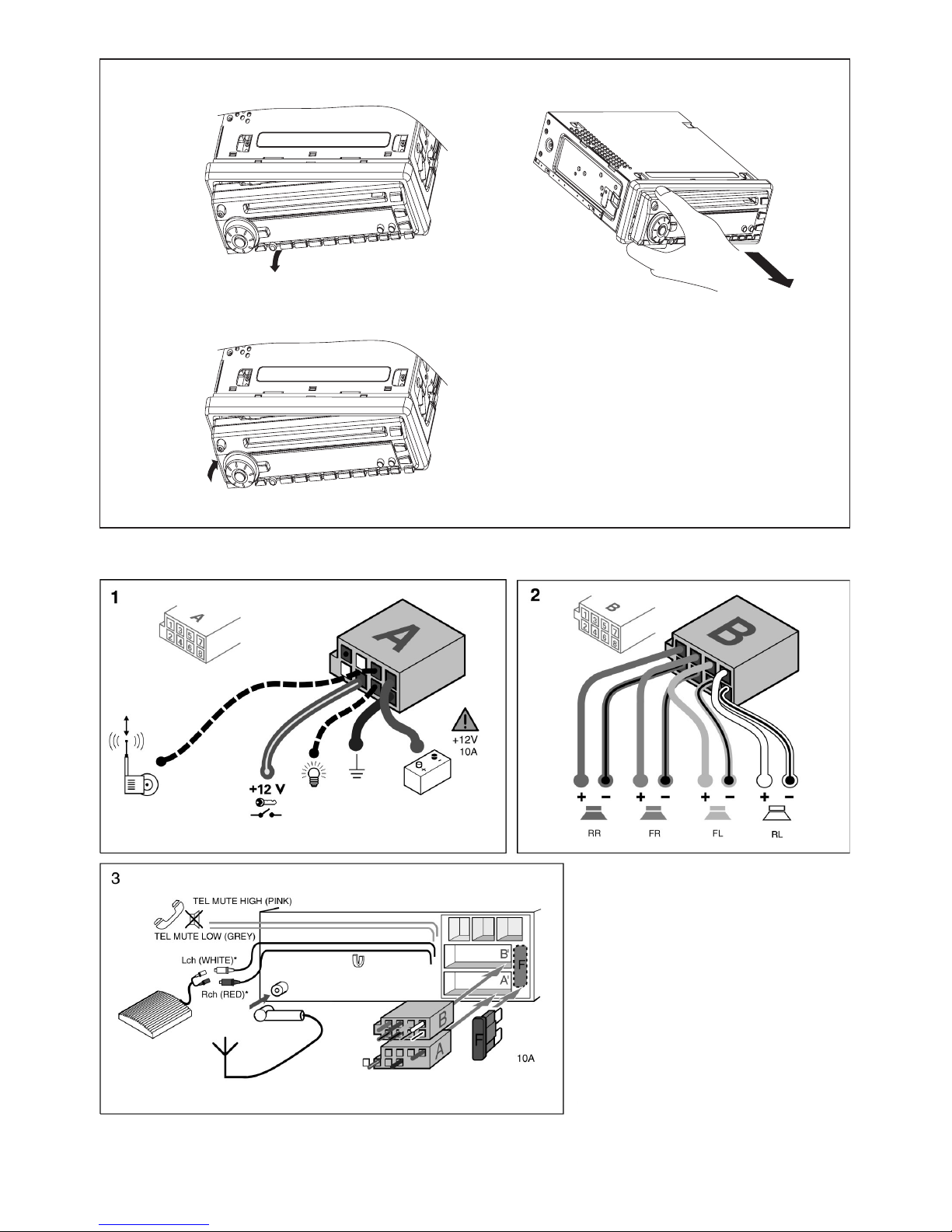
DIN FRONT-MOUNT (Method A)
Installation of the unit
1. Metal Sleeve
Install the metal sleeve in the dashboard.
For optimal performance of the CD
player, the metal sleeve should be
positioned horizontally (between –10 and
+30). Fix metal sleeve into place by
pressing the metal tags outwards using
screwdriver.
2. Front Mounting
Slide the radio into the metal sleeve until
the springs at either side of the radio
snap into the openings of the sleeve.
3. Removing Radio
Insert the levers supplied with the unit
into the grooves at both sides of the unit
until they lock. Pull the levers toward
you makes it possible to remove the unit
from the dashboard.
JIN REAR-MOUNT (Method B)
Installation using the screw holes on the
sides of the unit.
Remove the outer rim around the front panel
and the side springs. Select a position
where the screw holes of the mounting
bracket and the screw holes of the radio
become aligned and tighten the screws at
2 places on each side.
182
53
See details at the back of the cover page
for remove (figure A) and install (figure B)
the front panel.
1. Press the release button and pull-off the
front panel. Keep front panel into the
case.
2. To install the front panel, insert the panel
into the housing, slide in to the right hand
side and push in till locked.
3. Make sure the panel is properly installed.
Otherwise, abnormalities occurs on the
display or some keys will not function
properly.
HOW TO REMOVE AND INSTALL THE
FRONT PANEL
SECURITY IDENTIFICATION NUMBER
• A security identification number is stated
on the “Security Card” . Show this card
as a proof of ownership, when the set is
stolen, when the detachable front is lost
or when requesting service.
• Do not keep the “Security Card” in your
car .
Page 5

7
• ILLUMINATION COLOR
Press the button (12) for 2 seconds to
change the color of LCD.
• RESET
RESET button (26) is placed on the front
panel and must be activated with either a
ball point pen or thin hard object.
The RESET button (26) is to be activated
for the following reasons:
- Initial installation of the unit when all
wiring is completed.
- All the function buttons do not operate.
- Error symbol on the display.
Note: Pressing the RESET button (26)
will erase your stored stations in the
memory.
• RDS CLOCK
Press DISP button (4) to view RDS clock
time from the received RDS station.
• ON/OFF
Switch on the unit by pressing any button,
except REL button (1) and the CD eject
button (9). When system is on, press
POWER button (3) to turn off the unit.
• VOLUME/BASS/TREBLE/BALANCE/
FADER ADJUSTMENT
Press SEL button (22) to select the
desired adjustment mode.
The adjustment mode will change in the
following order:
By turning AUDIO ADJUST button (2),
different setting levels can be adjusted.
Note: Bass/Treble selections are only
active when the DSP (Digital Sound
Processor) is switched off.
Press SEL button (22) for 2 seconds, it
will trigger a series of Advanced RDS
setting. Refer to RDS (Radio Data
System) operation section for details.
• SOUND
Press SOUND button (23) to turn on sound
DSP function (Digital Sound Processor) and
to select desired audio mode.
There are five kinds of mode as below:
Activating the DSP overrides the prior
selected Bass/Treble settings.
• LOUDNESS
Press LOUD button (8) for 2 seconds to
reinforce the bass output and display will
show “LOUD”. Press it for 2 seconds
again to release this function.
• MUTE
Press MUTE button (24) to silence the
receiver. Press it again to resume
listening.
• FLASHING LED
If the front panel is removed from the unit,
the LED (25) will be flashing.
• SOURCE
Press SOURCE button (12) to switch
between CD and Radio.
GENERAL OPERATION
FLAT CLASSICS POP M ROCK M DSP OFF
Volume Bass Treble Balance Fader
• BAND SELECTION
At tuner mode, press BAND button (8)
shortly to select the desired band.
The reception band will change in the
following order:
• STATION SELECTION
Press TUNE/TRACK buttons (10) or (11)
shortly to activate automatic seek
function. Press for 2 seconds until
“MANUAL” appeared on the display, the
manual tuning mode is selected. If both
buttons have not pressed for several
seconds, they will retune to seek tuning
mode and “AUTO” appeared on the
display.
• AUTOSTORE
- Automatic Memory Storing
Press AST button (7) for 2 seconds.
The radio searches for 6 strongest
stations and stores them into the
presets of the currently selected band.
Note: Any stations that were previously
stored in this memory bank are replaced
by the new stations.
RADIO OPERATION
FM1 FM2 FM3 MW LW
English
Page 6

- Program Scanning
Press P.SCAN button (7) shortly to scan
all preset stations throughout the entire
band.
• STATION STORE AND RECALL
Press any one of the preset button for 2
seconds to store the current tuned
frequency in this memory.
Previously stored information in this
button will be lost. Press any one of the
preset buttons briefly (1 to 6) to recall a
station, which had been stored in the
memory.
- When region is on, the current listening
program remains unchanged.
When region is off, it allows the reception
moves to the regional station.
Using PTY to Select Program
The PTY function allows you to search for
stations with a particular Program Type.
To select your program type, press the PTY
button (15):
Now you can select the music type or
speech type using preset keys 1 - 6 for your
selection as listed in below table:
While selecting PTY engagement, its
selection is implemented by preset button
as described in notes.
When PTY is selected, the radio starts to
search corresponding PTY information, and
stops of the corresponding PTY information
is detected.
If corresponding PTY information is not
found, normal radio reception is resumed.
Listening to Traffic Announcement
Traffic announcement can interrupt CD play
or radio listening when broadcast.
8
PTY music group PTY speech group PTY off
The RDS data are the PI, PS, TP, PTY, TA
and AF data.
PI: Program Identification Code
Code for identifying program
PS: Program Service Name
Broadcast station name data
expressed in alphanumerically
character
TP: Traffic Program Identification
Identification data for traffic information
broadcasting station
TA: Traffic Announcement Identification
Identification data showing traffic
information is being transmitted or not
AF: Alternative Frequencies
Frequency list of broadcasting station
transmitting the same program
Setting AF Mode
- Press AF button (13) briefly to switch
on/off AF mode.
- Whenever AF is switched on, symbol “AF”
appears on the display.
- The tuner will return to Alternative
Frequencies whenever the reception
signals getting worse.
- “ALARM” will be displayed when an
emergency broadcasting is received;
meanwhile sound output level will be
adjusted to the preset output level
automatically when the volume control is
set at minimum.
Regional Program Operation
- Press AF button (13) for 2 seconds to
switch on or off regional mode.
RDS (RADIO DATA SYSTEM) OPERATION
Preset number PTY MUSIC group
1 POP M, ROCK M
2 EASY M, LIGHT M
3 CLASSICS, OTHER M
4 JAZZ, COUNTRY
5 NATION M, OLDIES
6 FOLK M
Preset number PTY SPEECH group
1 NEWS, AFFAIRS, INFO
2 SPORT, EDUCATE,
DRAMA
3 CULTURE, SCIENCE,
VARIED
4 WEATHER, FINANCE,
CHILDREN
5 SOCIAL, RELIGION,
PHONE IN
6 TRAVEL, LEISURE,
DOCUMENT
Page 7

9
Briefly press the TA button (14) to select the
TA mode on or off.
When TA mode is on, you will hear the
Traffic Announcement when broadcast.
During traffic announcement, you can
interrupt it by short press of TA button (14),
without switching off the TA mode.
By doing so, the set will return to the
previous operating mode.
Long press on TA button (14) allows
ON/OFF selection of TA LOCAL/TA
DISTANT mode.
TA LOCAL will only allow traffic announcement
from strong station to come through.
TA DISTANT (“RDS TA DX”) selection will
allow all received announcements to
interrupt CD play or radio listening.
- MASK ALL mode:
Masked the AF which has different PI
and any other interfering non PI station
which having the same transmitting
frequency.
e) Option for Beep level
- Beep OFF:
No beep will be heard when pressing
of any buttons.
- Beep 2ND:
Beep sound will be heard with any long
press function.
- Beep ALL:
Beep will be heard when pressing any
button.
Press the SEL button (22) for 2 seconds to
enter the advanced RDS settings menu.
a) TA SEEK or TA ALARM
- TA SEEK mode:
When TP information gets lost at the
current station for retune time which is
set by RETUNE SHORT (30sec.) or
RETUNE LONG (90sec.), the radio start
to retune to next same PI station.
- TA ALARM mode:
When TP information gets lost at the
current station, beeps will be heard.
b) PI SOUND or PI MUTE
In some countries, there is a possibility
of having 2 different stations with same
frequencies but different PI.
If PI SOUND is selected, radio will switch
to the new PI station for few seconds
before switch back to current PI station.
If PI MUTE is selected, radio will mute
when a new PI station is received.
c) RETUNE L or RETUNE S
When PI information is not caught for
retune time, the radio start to retune to
next same PI station.
- RETUNE L mode:
Retune time selected as 90 seconds.
- RETUNE S mode:
Retune time selected as 30 seconds.
d) MASK DPI or MASK ALL
- MASK DPI mode:
Masked only the AF which has different PI.
ADVANCED RDS SETTINGS
Insert discs, autoplay track and time display.
• SELECT TRACKS
During CD operation, press
TUNE/TRACK buttons (10) or (11) to
advance or reverse to the previous track.
Track number is shown on display.
During CD operation, hold TUNE/TRACK
buttons (10) or (11) to fast forward or fast
reverse. CD play resume when you
release the button.
• PAUSE
Press PAUSE button (21) to pause CD
player. Press it again to resume play.
• REPEAT THE SAME TRACK
During CD operation, press REPEAT
button (19) to continuously repeat the
same track. Press again to stop repeat.
• TRACK SCAN
The scan function enables you to listen to
the first few seconds of each track.
Press SCAN button (20) to activate/
de-activate scan track.
•
PLAY ALL TRACKS IN RANDOM ORDER
During CD operation, press SHUFFLE button
(18) to play all tracks on the disc in random
order. Press again to cancel the function.
• EJECT
Press button (9) to stop CD playing and
eject the disc from the disc slot (5).
CD OPERATION
English
Page 8

• Playing a CD-R
Depending on the type of CD-R CD,
surface condition of the disc, as well as
the performance and condition of the CD
writer, certain CD-R CD may not operate
normally on this unit.
• Playing a “copy protected” nonconforming audio CD
Due to use of copy protection schemes of
some audio CDs which are non
conformance to international audio CDs
standards (Red Book), these type of copy
protected disc(s) may not play on this unit.
MP3 OPERATION
• HOW ARE MP3 FILES RECORDED AND
PLAYED BACK ?
MP3 files (song) can be recorded in
directory (album) . During recording, the
files and directories can be arranged in
the way similar to arranging files and
directories of computer data .
“Root” is similar to the root of a tree. Every
file and directory can be linked to and be
accessed from the root.
In compliance with ISO9660, the maximum
allowable depth of directories is eight (
10
n
Level
1
2
3
4
5
Root
1
2
3
4
5
6
1
4
15
13
7 8
16
14
10
11
12
5
6
9
3
2
20
17
19
21
18
MP3 directory / File configuration
Directory Depth
N
- Directories / Albums search order
- MP3 files, search and playback order.
Page 9

11
English
inclusive of root directory )
Playback, file search and directory search
orders on a disc are determined by writing
(encoding) application. Therefore , playback
order may be different from the sequence
of recording the directories and files .
Refer to the table for how MP3 files are
recorded, search and playback.
• PLAYING A MP3 DISC
You are able to play MP3 files that conform
to MPEG1-Layer 3 file-coding scheme
burned on a CD-R disc in ISO9660 format.
To listen to MP3 song, insert the MP3 disc
in the headunit, playback starts
automatically.
• SELECT SONG
In MP3 operation, there are four ways to
select the song
- Single step selection :
Press TUNE/TRACK button (10) or (11)
to advance or reverse the previous song
in single step
- Select in steps of 10 :
Press PRESET button 6 (16) or PRESET
button 5 (17) to advance or reverse the
songs in step of 10
- Select by album / song title :
Press MODE button (7) one time. Now
you can enter text-string of up to 16
characters of the desired song title by
using –
• encoder rotary knob (2), to select the
characters A to Z, 1 to 0 , blank, +, -,
_ or apostrophe ( ‘ ) .
• press OK button (22) to confirm entry
of each characters .
• press ENTER button (8) to start the
title search .
The display will list all characters related
song titles from disc, select the wanted
title by encoder rotary knob (2). Press
ENTER button (8) to confirm and start
the play.
N.B. : In case the selected title is an
album name, display will show ( ‘ ‘ ) .
• Use encoder rotary knob (2) to list all
songs under this album and select the
title
• Press ENTER button (8) to confirm
and start the play.
• Repeat the above steps if the newly
selected title is again an album.
- Select by Directory or Album :
Press MODE button (7) two times,
display will list all available albums and
songs. Select the desired album/songs
by using encoder rotary knob (2) and
ENTER button (8) to confirm.
If the selected title is a song, it starts to
play .
If the selected title is an album name,
display will show ( ‘ ‘ ) , then
• Use encoder rotary knob (2) to list all
songs under this album and select the
title
• Press ENTER button (8) to confirm
and start the play.
• Repeat the above steps if the newly
selected title is again an album.
N.B.: The headunit able to play multilevel directory/album .
• ENTER & RETURN OF DIRECTORY
/ALBUM
Whenever the display show ( ‘ ‘ ), press
ENTER button (8) allow user to exit or
return to the previous directory level .
• PAUSE
Press PAUSE button (21) to pause MP3
player. Press it again to resume play.
• REPEAT THE SAME SONG
Press REPEAT button (19) to continuously
repeat the same song. Press again to
cancel repeat function.
• SCAN
The scan function enables you to listen to
the first few seconds of the song. Press
SCAN button (20) to activate / de-activate
scan function.
Page 10

12
• PLAY SONG IN RANDOM ORDER
During MP3 operation, press SHUFFLE
button (18) to play songs in random order.
Press again to cancel the function.
• EJECT
Press button (9) to stop MP3 function and
eject the disc from disc slot (5).
• DISPLAY INFORMATION
Press DISP button (4), following information
are shown in sequence :
Clock ID3 TAG ( if available : song title,
directory name, artist name, other contents…)
Radio frequency PTY .
• Notes on MP3
- The unit cannot read an MP3 file that
has a file extension other than “.MP3” .
- The display only support English
language characters A to Z, 0 to 9, +, -,
_ and apostrophe ( ‘ ) .
- The unit can play up to maximum 256
tracks and support maximum 128
directories per disc .
- The unit can display the directory/album
name of maximum 16 characters and
file/song name of maximum 28
characters.
- The unit plays only the first session of
the disc ( can be CD audio or MP3 ) if
the disc contains both CD audio tracks
and MP3 files .
- Make sure that MP3 CD is burned in
format as a data disc and NOT as an
audio disc .
- To enjoy high quality sound. It is
recommended to convert the MP3 files
with a sampling frequency of 44.1KHz
and fixed bit rate of 128kbps or higher
.
The following suggestions help you care for
the product so that you can enjoy it for
years.
1. Keep the product dry. If it does get wet,
wipe it dry immediately. Liquids might
contain minerals that can corrode the
electronic circuits.
2. Keep the product away from dust and
dirt, which can cause premature wear of
part.
3. Handle the product gently and carefully.
Dropping it can damage circuit boards
and cases, and can cause the product
to work improperly.
4. Wipe the product with a dampened cloth
occasionally to keep it looking new.
Do not use harsh chemicals, cleaning
solvents, or strong detergents to clean
the product.
5. Use and store the product only in normal
temperature environment.
High temperature can shorten the life of
electronic devices and distort or melt
plastic parts.
For CD Player
As dust tends to accumulate in the CD slot,
clean it every once in a while. Your CDs
can get scratched if you put them in a dusty
CD slot.
Care of Discs
Playing a CD that is dirty, scratched or
warped can cause the sound to skip and
the unit to operate incorrectly, resulting in
worsened sound quality. Take the following
precautions to prevent your CDs from
getting scratched or damaged.
1. Avoid making fingerprint on the disc
when handling it.
2. Put the disc back in the box immediately
after eject.
3. Do not expose the disc to heat and direct
sunlight.
4. Clean the CD frequently with
commercially available cleaning cloth or
soft cotton cloth.
MAINTENANCE
Page 11

13
SPECIFICATION
GENERAL
Power Supply Requirements : DC 12 Volts, Negative Ground
Chassis Dimensions : 180 (W) x 155 (D) x 50 (H)
Tone Controls
- Bass (at 100 Hz) : + 10 dB / – 10 dB
- Treble (at 10 KHz) : + 10 dB / – 10 dB
Maximum Output Power : 4 x 50W
- Set Illumination : Switchable Orange/Green
- Safety fuse : 10 Ampere (max.)
CD PLAYER
Signal to Noise Ratio : More than 85 dB
Channel Separation : More than 70 dB
Frequency Response : 20 Hz - 20 KHz
RADIO
FM
Frequency Coverage : 87.5 to 108 MHz
IF : 10.7 MHz
Sensitivity (S/N = 30 dB) : 3 µV
Stereo Separation : > 30 dB
MW
Frequency Coverage : 522 to 1620 KHz
IF : 450 KHz
Sensitivity (S/N = 20 dB) : 32 dBu
LW
Frequency Coverage : 144 to 288 KHz
IF : 450 KHz
Sensitivity (S/N = 20 dB) : 35 dBu
English
Page 12

14
TROUBLE SHOOTING
Before going through the check list, check wiring connection. If any of the problems
persist after check list has been made, consult your nearest service dealer.
Symptom Cause Solution
No power. The car ignition is not on. If the power supply is properly connected
to the car accessory terminal, switch the
ignition key to “ACC”.
The fuse is blown. Replace the fuse.
Disc cannot Presence of CD disc inside Remove the disc in the player, then put a
be loaded or the player. new one.
ejected.
Inserting the disc in reverse Insert the compact disc with the label
direction. facing upward.
Compact disc is extremely Clean the disc or try to play a new one.
dirty or defective disc.
Temperature inside the car Cool off or wait until the ambient
is too high. temperature return to normal.
Condensation. Leave the player off for an hour, then try
again.
No sound. Volume is in minimum. Adjust volume to a desired level.
Wiring is not properly connected
Check wiring connection.
due to telephone mute.
Ensure your phone MUTE is correctly connected.
Sound skips. The installation angle is not Adjust the installation angle to less than
more than 30 degrees. 30 degrees.
The disc is extremely dirty Clean the compact disc. Then try to play
or defective. a new one.
The operation
The built-in microcomputer Press the RESET button.
keys do not is not operating properly Front panel is not properly fixed into its
work. due to noise. place.
Contacts between front and main unit are
dirty. Clean contacts with a cotton bud
soaked in isopropyl alcohol.
The radio The antenna cable is not Insert the antenna cable firmly.
does not work.
connected.
The radio station
automatic The signals are too weak. Select a station manually.
selection does
not work.
 Loading...