

Page 1
New Generation 2009
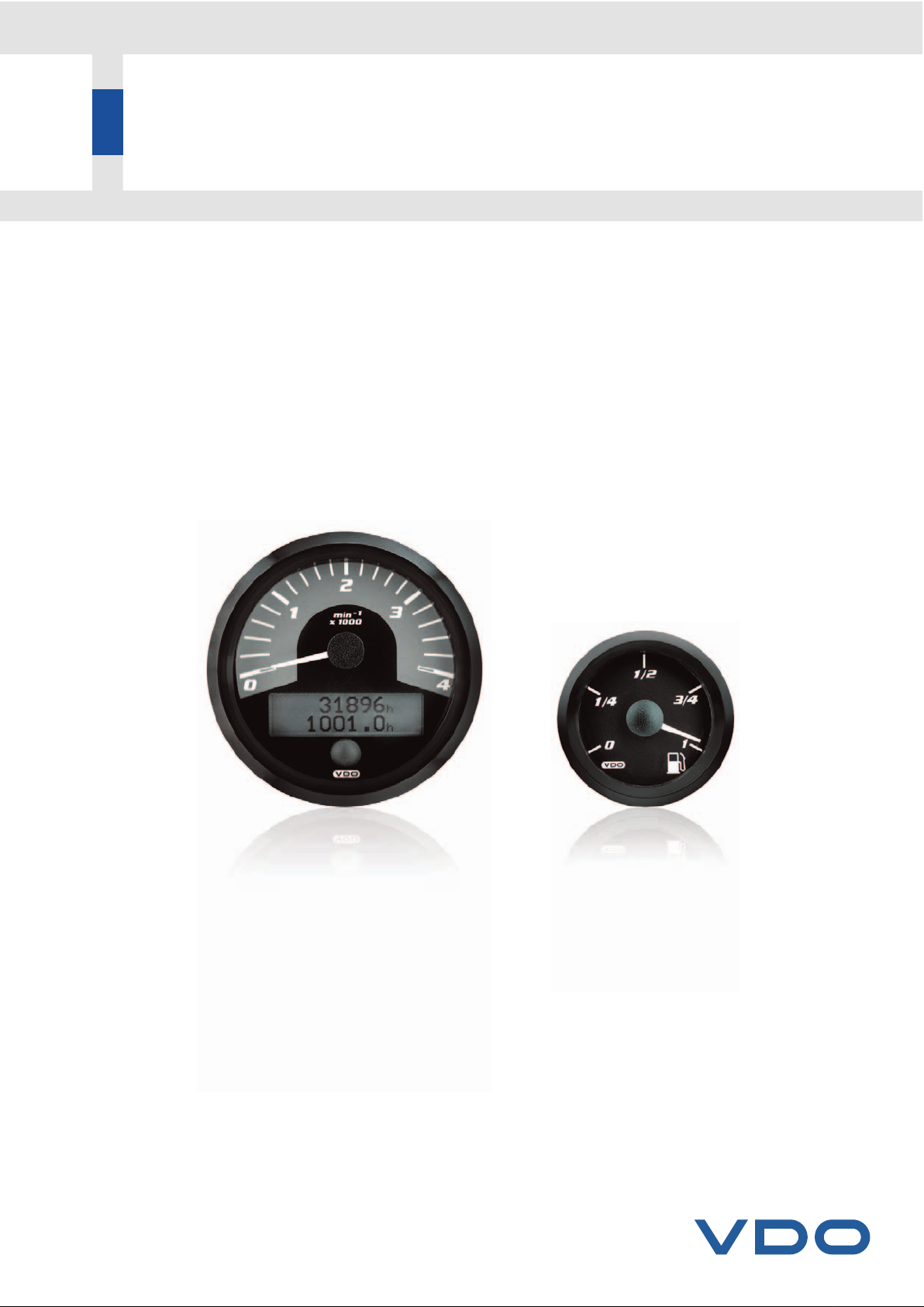
Flexible instrumentation with CAN bus technology
www.vdo.com
CANcockpit
Product Manual
VDO - eine Marke des Continental-Konzerns / VDO - Atrademark of the Continental Corporation
Page 2

Topic Chapter
Safety Instructions 1
Description of Functions 2
Installation Instructions 3
Testing Instructions ▼ 4
Software-Description 5
System Components, Spare Parts and Accessories 6
Data Sheets 7
General Information 8
Sales and Service Informations 9
▼ = will follow
The reproduction, distribution and utilization of this document as well as the communication of its contents to others without
express authorization is prohibited. Offenders will be held liable for the payment of damages. All right reserved in the event of
the grant of a patent, utility model or design.
Overview of Chapter
Product Manual
Technische Änderungen vorbehalten Technical details subject to change
TU00-0726-0000002
0609
Page 3

Technische Änderungen vorbehalten Technical details subject to change
1 - 1
TU00-0736-0000002
0609
1. Safety Instructions
Product Manual
Contents
Contents
1.1 Installation 2
Before installation 2
During installation 3
After installation 3
1.2 Electrical Connection 4
1.3 Sensors 5
1.3.1 Pressure Sensor for Oil 5
1.3.2 Temperature Sensor for Oil 6
1.3.3 Temperature Sensor for Engine Coolant 7
1.3.4 Fuel Level Sensor (Lever Type Sensor/Tubular Type Sensor) 8
Page 4
1.1 Installation
• The product is only designed for use in land-bound vehicles (except motorcycles).
• Make sure that the engine cannot be unintentionally started during installation.
Before installation
• Withdraw ignition key from ignition lock.
• Note down all data in temporary electronic memories.
• Before installation refer to the vehicle documents for details of vehicle type and any special features.
• Refer to the construction diagrams to find out the positions of the fuel/hydraulic/pneumatic and electrical lines.
• Take account of any modifications to the vehicle which have to be considered during installation.
• Failure to use the product correctly may cause harm to people, property and the environment. Therefore make sure you
use our product correctly.
• Basic knowledge of vehicle electrics and mechanics is necessary for installation to prevent harm to people, property and
the environment.
• The product has been developed, manufactured and tested in accordance with the basic safety requirements of EC directives and the acknowledged state of the art.
• Short circuits
Short circuits in the vehicle's wiring can cause cable fires, battery explosions and damage to other electronic systems.
Therefore disconnect the minus pole of the vehicle battery before starting work.
If the vehicle has supplementary batteries, the minus poles of these batteries should also be disconnected.
• Modifying or tampering with the product may affect safety. Therefore it must not be modified or tampered with.
• When removing/installing seats, covers and the like, make sure that you do not damage lines or release plug connections.
• Possible data loss
When the batteries' minus poles are disconnected, all the temporary electronic memories lose their entered data.
Therefore, note down all the relevant data for re-programming before disconnection.
1. Safety Instructions
Product Manual
Technische Änderungen vorbehalten Technical details subject to change
1 - 2
TU00-0736-0000002
0609
No smoking!
No naked flames or lights!
Page 5

1.1 Installation
During installation
• During installation make sure that the product's components do not affect or restrict vehicle functions and are themselves not damaged.
• Only install undamaged parts in vehicles.
• During installation make sure that the product does not impair the field of vision and that the product is not positioned
within the impact range of the driver's or passenger's heads.
• When selecting the installation location, make sure there is sufficient space behind the drilled holes and the installation
opening.
• Take account of the routing of lines and cable leads.
• Do not select an installation location within the mechanical and electrical range of the airbag.
• Do not drill holes or cut openings in load-bearing or stabilizing struts or members.
• Err on the small side when predrilling installation apertures with cone-type cutters, compass or jig saws, or files, enlarge if necessary and complete. Deburr edges. Always follow the tool manufacturer's safety instructions.
• When working beneath the vehicle, secure the vehicle in accordance with the vehicle manufacturer's instructions.
• If any work is necessary while the engine is running, take special care. Only wear suitable working clothes because of
the risk of injury due to pinching and burning. Long hair should be worn in a hair net.
• Only use the envisaged multimeters or diode-test lamps to measure wattages and currents in motor vehicles. The use
of conventional test lamps can cause damage to control units and other electronic systems.
After installation
• Firmly connect the earth cable to the minus pole of the vehicle battery.
• (Re-)program the data in the temporary electronic memories.
• Test all(!) vehicle functions.
• CANcockpit components to be cleaned with clear water only.
Observe the IP-degrees of protection (DIN 40050).
1. Safety Instructions
Product Manual
Technische Änderungen vorbehalten Technical details subject to change
1 - 3
TU00-0736-0000002
0609
Page 6
1.2 Electrical Connection
• Take account of the cable cross section
A reduction in the cable cross section results in a higher current density. This can cause the cable to heat up.
• When laying electric cables, use existing cable ducts and routes but without laying cables parallel to ignition cables or
cables leading to high current consumers. Fix the cables with cable tape or adhesive tape.
• Do not route cables over mobile components. Do not fasten cables to the steering column.
• Make sure that the cables are not exposed to tensile, compressive or shear forces.
• If the cables are routed through drilled holes, protect them with rubber sleeves or the like.
• Strip cables only with a cable stripper. Adjust the stripper so that no strands are damaged or severed.
Solder new cable connections only with the soft soldering process or use standard crimp connectors.
• Crimp connections should only be made with a crimping tool. Follow the tool manufacturer's safety instructions.
• Insulate exposed strands so that no short circuiting can occur.
• Faulty wiring can cause short circuiting. Wire the cables only in accordance with the electrical connection diagram.
1. Safety Instructions
Product Manual
Technische Änderungen vorbehalten Technical details subject to change
1 - 4
TU00-0736-0000002
0609
Connect the cables in accordance with the electrical connection diagram.
Page 7
Technische Änderungen vorbehalten Technical details subject to change
1 - 5
TU00-0736-0000002
0609
1.3 Sensors
1.3.1 Pressure Sensor for Oil
❒ Sensor installation location: At the place provided by the engine manufacturer, equipment manufacturer or car manu-
facturer in the oil circulation system (most often in place of the oil pressure switch).
❒ Sensor installation only when engine is cold.
❒ When removing the oil pressure switch or the screw from the drilled hole for the oil pressure measuring system, collect
the oil running out of the system in a proper container and dispose of it in accordance with legal regulations.
max.
❒ The values mentioned in the following table for the maximum tightening
torque (Nm max.) refer exclusively to the load-bearing capacity of products.
Prior to using the product, it is important to ask the manufacturer of the vehicle, equipment system or engine in each instance for the maximum torque (? Nm max.) value for the threaded hole into which the product is to be
screwed. Non-observance of the maximum tightening torque specified for
the threaded hole in each instance can result in damage to the vehicle, engine or equipment system.
❒ If the connection thread is cylindrical, a sealing washer or a sealing ring made of copper must be fitted.
❒ Following sensor installation, fill up the system with the required quantity of specified oil.
1. Safety Instructions
Product Manual
M10 x 1 30 Nm
1/8 in. BSPF 30 Nm
1/8 - 27 NPTF 30 Nm
R 1/8 DIN 2999 30 Nm
M12 x 1,5 40 Nm
M12 x 1 50 Nm
M14 x 1,5 50 Nm
1/4 in. BSPF 60 Nm
1/4 - 18 NPTF 60 Nm
3/8 - 18 NPTF 60 Nm
M16 x 1,5 80 Nm
3/8 - 18 Dryseal NPTF 80 Nm
M18 x 1,5 100 Nm
Page 8

1.3 Sensors
1.3.2 Temperature Sensor for Oil
❒ Sensor installation location: At the place provided by the engine manufacturer, equipment manufacturer or car manu-
facturer in the oil circulation system (e. g. oil drain plug).
❒ Sensor installation only when engine is cold.
❒ When removing the oil drain plug, collect the oil running out of the system in a proper container and dispose of it in ac-
cordance with legal regulations.
max.
❒ The values mentioned in the following table for the maximum tightening tor-
que (Nm max.) refer exclusively to the load-bearing capacity of products.
Prior to using the product, it is important to ask the manufacturer of the vehicle, equipment system or engine in each instance for the maximum torque (? Nm max.) value for the threaded hole into which the product is to be
screwed. Non-observance of the maximum tightening torque specified for
the threaded hole in each instance can result in damage to the vehicle, engine or equipment system.
❒ If the connection thread is cylindrical, a sealing washer or a sealing ring made of copper must be fitted.
❒ Following sensor installation, fill up the system with the required quantity of specified oil.
1. Safety Instructions
M10 x 1 10 Nm
M10 x 1.5 10 Nm
1/8 - 27 NPTF 10 Nm
M12 x 1.5 15 Nm
1/2 - 20 Gang 15 Nm
M14 x 1.25 20 Nm
M14 x 1.5 20 Nm
5/8 - 18 UNF - 3A 20 Nm
1/2 In. 20 Whit. S 20 Nm
1/4 - 18 NPTF 20 Nm
M16 x 1.5 30 Nm
M18 x 1.5 30 Nm
M20 x 1.5 30 Nm
M22 x 1.5 30 Nm
M24 x 1.5 30 Nm
M26 x 1.5 30 Nm
1/2 - 14 NPTF 30 Nm
3/8 - 18 NPTF 30 Nm
R 1/2 30 Nm
R 3/8 30 Nm
3/8 - 18 Dryseal NPTF 30 Nm
3/4 - 16 UNF-3A 30 Nm
Product Manual
Technische Änderungen vorbehalten Technical details subject to change
1 - 6
TU00-0736-0000002
0609
Page 9
1.3 Sensors
1.3.3 Temperature Sensor for Engine Coolant
❒ Sensor installation location: At the place provided by the engine manufacturer, equipment manufacturer or car manu-
facturer in the coolant circulation system (e.g. in place of the temperature warning switch) or in the coolant hose.
❒ Sensor installation only when engine is cold.
❒ Collect the coolant running out of the system in a proper container and dispose of it in accordance with legal regulations.
max.
❒ The values mentioned in the following table for the maximum tightening tor-
que (Nm max.) refer exclusively to the load-bearing capacity of products.
Prior to using the product, it is important to ask the manufacturer of the vehicle, equipment system or engine in each instance for the maximum torque (? Nm max.) value for the threaded hole into which the product is to be
screwed. Non-observance of the maximum tightening torque specified for
the threaded hole in each instance can result in damage to the vehicle, engine or equipment system.
❒ If the connection thread is cylindrical, a sealing washer or a sealing ring made of copper must be fitted.
❒ Following sensor installation, fill up the system with the required quantity of the compositon specified coolant.
1. Safety Instructions
Product Manual
Technische Änderungen vorbehalten Technical details subject to change
1 - 7
TU00-0736-0000002
0609
M10 x 1 10 Nm
M10 x 1.5 10 Nm
1/8 - 27 NPTF 10 Nm
M12 x 1.5 15 Nm
1/2 - 20 Gang 15 Nm
M14 x 1.25 20 Nm
M14 x 1.5 20 Nm
5/8 - 18 UNF - 3A 20 Nm
1/2 In. 20 Whit. S 20 Nm
1/4 - 18 NPTF 20 Nm
M16 x 1.5 30 Nm
M18 x 1.5 30 Nm
M20 x 1.5 30 Nm
M22 x 1.5 30 Nm
M24 x 1.5 30 Nm
M26 x 1.5 30 Nm
1/2 - 14 NPTF 30 Nm
3/8 - 18 NPTF 30 Nm
R 1/2 30 Nm
R 3/8 30 Nm
3/8 - 18 Dryseal NPTF 30 Nm
3/4 - 16 UNF-3A 30 Nm
Page 10
1.3 Sensors
1.3.4 Fuel Level Sensor (Lever Type Sensor/Tubular Type Sensor)
❒ An installation opening remaining to be made in the tank at a suitable point for supply level measurement or at an in-
stallation flange or installation opening already provided by the tank manufacturer.
❒ If an installation opening must be made, the tank must be completely drained first. Fill the fuel into an approved contai-
ner.
❒ Risk of explosion exists due to presence of residual gases in the tank! Make sure that the tank is aired
sufficiently (approx. 10 minutes).
❒ Make a preliminary hole in the installation opening using a drill and then finish the hole using a compass saw or piercing
saw. Comply with the safety instructions of the tool manufacturer. Clean the tank of residue from the drilling or sawing
work.
❒ The safety instructions given by the welding equipment manufacturer and the working regulations applying to welding
work must be respected when welding the tank flange.
1. Safety Instructions
Product Manual
Technische Änderungen vorbehalten Technical details subject to change
1 - 8
TU00-0736-0000002
0609
Page 11

Technische Änderungen vorbehalten Technical details subject to change
2 - 1
TU00-0736-0000002
0609
Contents
Contents
1. System 3
1.1 Main Features 3
1.1.1 Block Diagram CANcockpit 3
1.2 Mechanical Concept 3
1.3 Safety Concept 4
1.3.1 Sensors 4
1.3.2 System Check 4
1.3.3 Satbus 4
1.3.4 WINgauge 4
2. Master Gauges 5
2.1 General Features 5
2.1.1 Main Functions 5
2.2 Mechanical Concept 6
2.2.1 Master dia. 80 mm 6
2.2.2 Master dia. 85 mm 6
2.2.3 Master dia. 100 mm 6
2.3 Input Signal Processing 7
2.3.1 Analog Inputs 7
2.3.1.1 Grounding Concept 7
2.3.1.2 Sensors 7
2.3.2 Input Signal Processing applied to the two frequency inputs 7
2.3.3 Input Signal Processing for CANbus messages 8
2.4 PIN Assignment Description 9
2.4.1 Technical Description 9
2.5 Display Functions 12
2.5.1 Navigation through Display 12
2.5.2 Display Layout 12
2.5.3 Display Functions 14
2.5.3.1 Main Display (Odometer, Hourmeter) 14
2.5.3.2 Alarm Display 14
2.5.3.3 CAN DTC Display 15
2.5.3.4 Warning Display 15
2.5.3.5 Service Message 16
2.5.3.6 Physical Value Display 16
2.5.4 Alarm- and Warning Functions 17
2.5.4.1 Description of the Outputs 17
2.5.4.2 Switch Output Acknowledgement Function 17
2.5.4.3 Alarm and Warning Trigger Conditions 18
2.5.4.4 Alarm and Warning Trigger enabling with Engine running 18
2.5.4.5 Alarm and Warning State Diagram (Maximum Value Algorithm) 19
2. Functional Specification
Product Manual
Page 12

2.5.5 Service 21
2.5.5.1 Reset of Service messages 21
2.5.6 CAN (SAE J1939) DTC (Diagnostic Trouble Codes) messages 22
2.5.6.1 CAN SAE J1939 Elements 22
2.5.6.2 CAN DTC Information Display Requirements 23
2.5.6.3 CAN DTC Display Functions 23
2.5.6.4 Speedometer Master Gauge 25
2.5.6.5 Tachometer Master Gauge 27
3. Satellite Gauges 28
3.1 Mechanical concept 28
3.2 Fault modes 28
3.3 Satellite gauge address 29
3.4 Warning Lamp inside the Satellite Gauge 29
3.5 Tolerance 29
A. Technical Data 30
B. Applied Standards 31
2. Functional Specification
Product Manual
Technische Änderungen vorbehalten Technical details subject to change
2 - 2
TU00-0736-0000002
0609
Page 13
1. System
1.1 Main Features
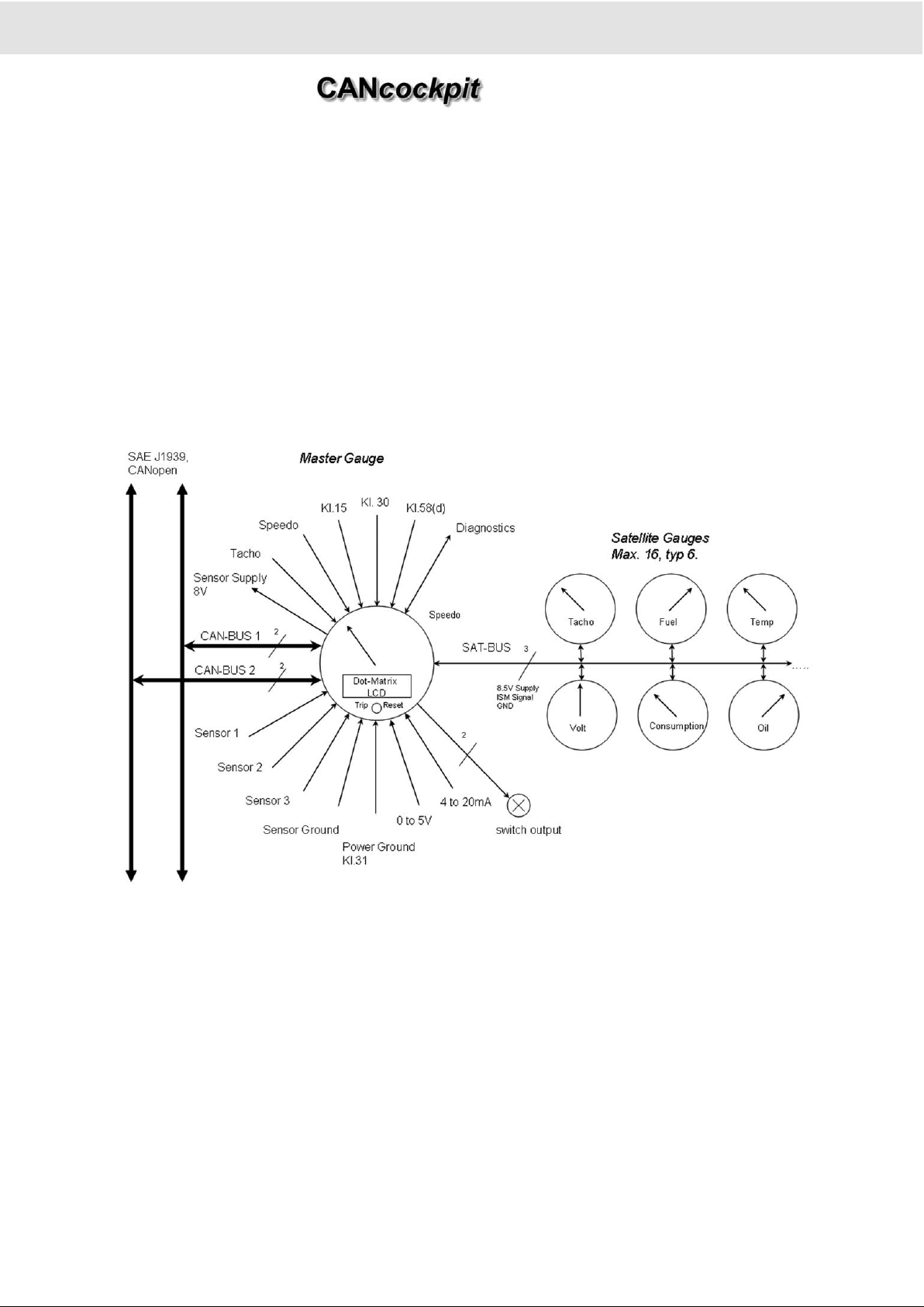
• Master-Slave relationship between Master gauge and other instruments
• Up to 16 Slave functions on one Master instrument or 32 with the use of two Master instruments
• CAN protocol flexibility ( processing two protocols simultaneously)
• Modular "plug & play" as needed
• Analogue sensor compatible
• Frequency inputs
• Dot-matrix information display
• Switch outputs available
• Flexible to customer needs
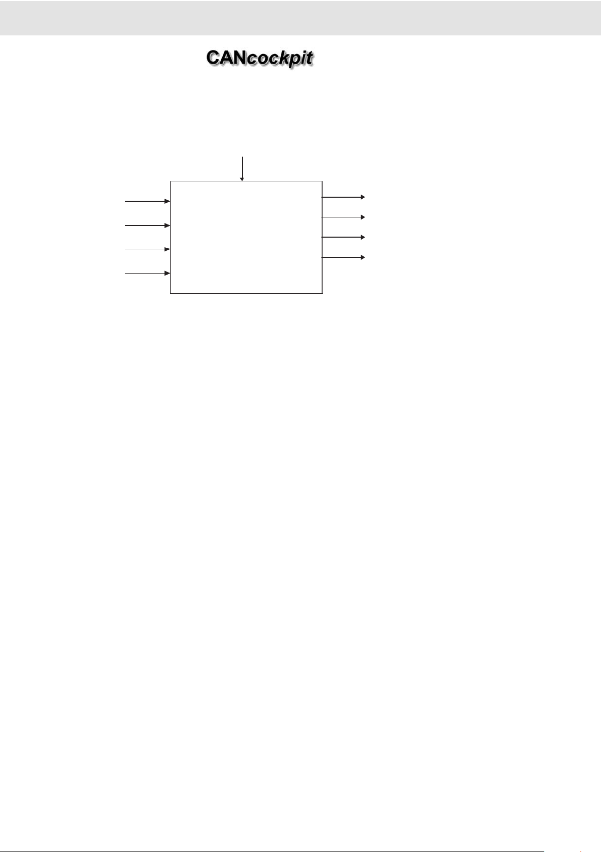
1.1.1 Block Diagram CANcockpit
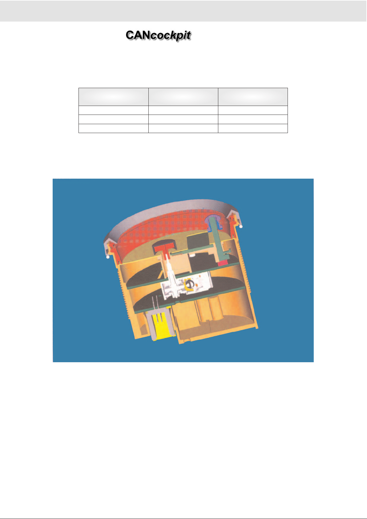
1.2 Mechanical Concept
The Masters are 80, 85 and 100 mm in diameter, the Satellite gauges dia. 52, 80 and 100 mm.
The dials are translucent backlighted. The illumination of the gauges is realised with white LED's.
The backlighting of the LCD has a yellow LED. The warning lamp in the slave can have a red or yellow LED.
The housing and bezel are made of non-flammable plastic, the design is like a triangle with the black color RAL 9005. The be-
zel is clipable. The lens is flat and frosted. The pointer has a PC hub in black and the pointer arm is OL5105 (white -coated on
the underside). The pointer type is translucent illuminated.
The housings have an indent in the thread at 6 o'clock position, so that an optional key can be
used according to SAE J1226 and SAE J 1399.
The movements are front-mounted stepper motors MW2000, only clockwise indication.
2. Functional Specification
Product Manual
Technische Änderungen vorbehalten Technical details subject to change
2 - 3
TU00-0736-0000002
0609
Page 14

1.3 Safety Concept
1.3.1 Sensors
Analog sensors can be checked for short and open circuit.
1.3.2 System Check
When the trip-reset button is pressed while ignition is being turned on, the system-check function is activated and clears the
contents of the DTC List.
If there are any active service messages, they will be displayed on the Dot-Matrix Display starting with the first active service
message. If the reset button is then pressed and held for 5 seconds or longer, this service message will be reset. The next
active service message is displayed thereafter.
To proceed to the next active service message without resetting the displayed code, the button needs to be pressed shortly
(<5 sec). If all active service codes have been displayed, the system check function is started as described below:
1. All warning lamps and illumination of all gauges are activated for 3 seconds.
2. The Master gauge initializes all configured satellite gauges and waits until they are ready or a Satbus timeout occurs.
3. During time.this, all LCD-Dots are turned on for about 1.5 sec, all pointers are moved to their end value
4. Then all LCD-Dots are turned off and the pointers move back to zero, for about 1.5 sec too, and all warning lamps and
illumination will be turned off
5. Firmware version and Check sum of the EEPROM in hexadecimal format are displayed for about 10 sec.
The display format is as follows:
XX represents a hex-coded value
1.3.3 Satbus
After ignition for synchronisation the Master gets feedback from the satellites.
A timeout function can be programmed too. If more satellites are configured, the Master will not get feedback from all gauges.
After a timeout of about 14 seconds, the Master will act as described before, when the Master gets feedback from all satellites.
During normal operation there is no feedback from the satellites.
1.3.4 WINgauge
A system diagnosis function for testing all in- and outputs is implemented in the WINgauge Software.
2. Functional Specification
Product Manual
Small
display
line
Format Description
2 hXX sXX.XX dd_mm_yyyy hXX specifies the Hardware version relevant to the Firmware
sXX.XX refers to the Firmware version, for example s12.A8 stands for V06
dd_mm-yyyy is the Firmware date in day, month and full-year format.
4 nXXXXwXXyXX cXXXXXX nXXXX is the WINgauge serial number of the device as programmed into the
EEPROM.
wXXyXX displays the production week and year in short format.
cXXXXXX shows the actual 3-byte Checksum of the EEPROM as calculated during
the system check.
Technische Änderungen vorbehalten Technical details subject to change
2 - 4
TU00-0736-0000002
0609
Page 15
Technische Änderungen vorbehalten Technical details subject to change
2 - 5
TU00-0726-0000002
0609
2. Master Gauges
2.1 General Features
The design concept for this design includes:
• 2x High-speed Full-CANbus interface V2.0B compatible.
• Half-duplex serial link to satellite gauges.
• VMC SCAL CDVV Microcontroller with identical firmware.
• Stepper motor MW2000 directly controlled by Microcontroller.
• Satellite gauges use SM2 stepper motor driven by ISM IC.
• LED illumination concept.
• 132 x 33 dots matrix LCD.
• Wide input voltage range switch mode power supply.
• Diagnostic Interface for configuration.
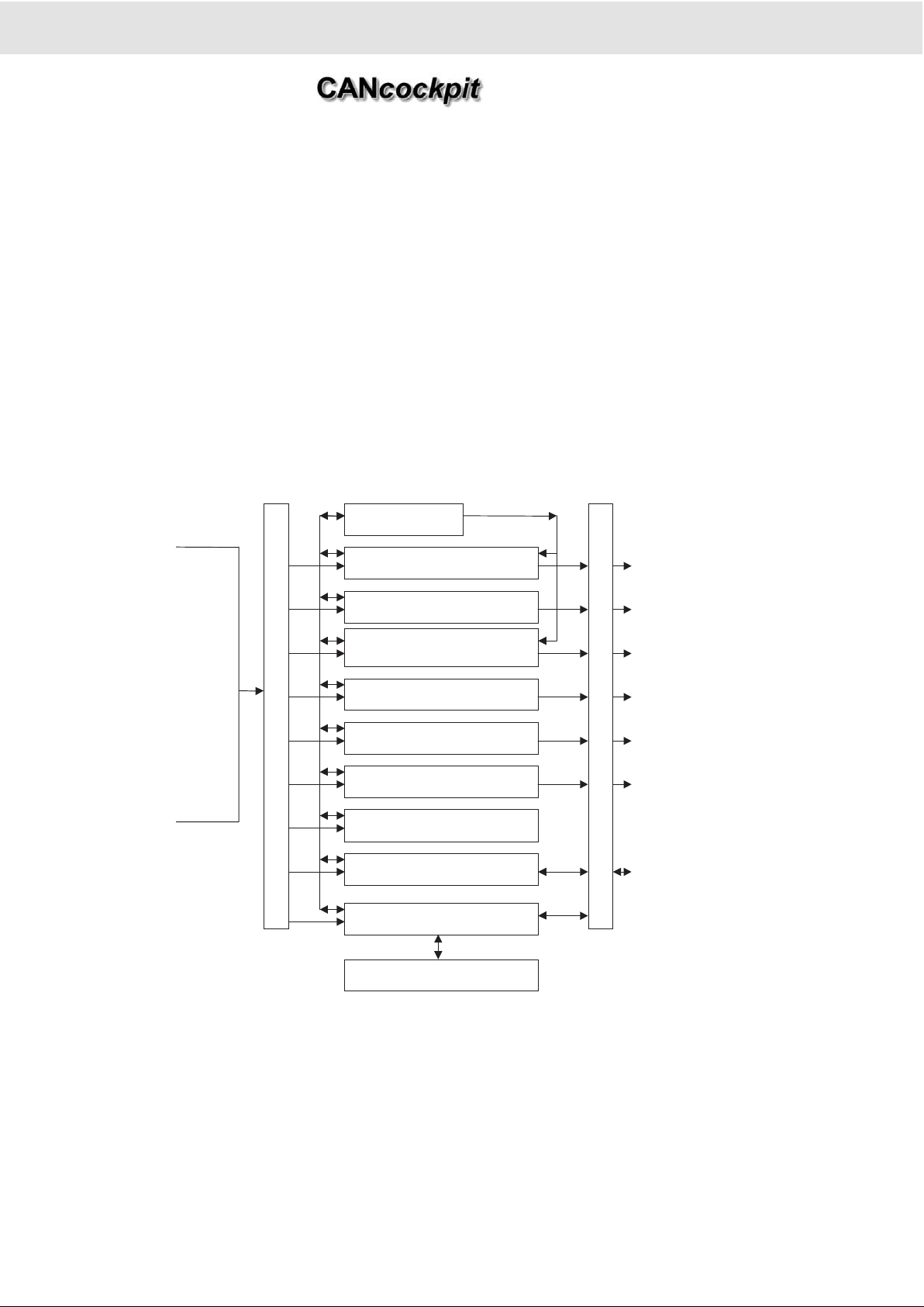
2.1.1 Main Functions
2. Functional Specification
Product Manual
Inputs
Outputs
CAN_1
CAN_2
Frequency_1
Frequency_2
Sensor Input_1
Sensor Input_2
Sensor Input_3
4 to 20 mA
Voltage Input
Illumination
term.15
term.30
Inp
ut
Sig
nal
Pr
oc
es
sin
g
Analogue Gauge Functions
W arning Fu nc ti ons
Odomete r,
Tripmeter
Hourmeter
,
Triphourmeter
Service Intervals
Illumination Control
Power Supply Control
Parameter Memory (EEPROM)
Diagnostics
Frequency-Divider
Ou
tpu
t
Sig
nal
Pr
oc
es
sin
g
Flash-Boot-Loader
Intern al MW2000
SatBus
-Gauges
LCD
Sat-Gauge Warning Lamps
Switch Output_1
Switch Output_2
LCD
LCD
Master Gauge Illumination
SatBus
-Gauge Illumination
Master Gauge Supply
SatBus
Supply
Sensor Supply
K-Line Diagnostic s
Diagnostic Trouble Codes
Page 16
2.2 Mechanical Concept
As the same LCD is used for different Master gauge diameters the pointer position has different eccentricities and indication
angles.
The connectors are 26-Pin MODU II-Connector and 4-Pin MATE-N-LOK from AMP.
2.2.1 Master dia. 80 mm
Two PCB's are necessary for this diameter. They are connected with a standard pin connector
and two distance towers.
2.2.2 Master dia. 85 mm
The PCB assemblies and their corresponding parts of the Ø 80 mm and Ø 85 mm gauges are identical. The difference between the two gauges is the position of the stepper motor on the PCB so that the eccentricity of 7 mm in the Ø 80 mm gauge
can be reduced to 4.5 mm in the Ø 85 mm gauge.
2.2.3 Master dia. 100 mm
For this size, only one PCB assembly is necessary. Input Signal Processing.
Gauge diameter [mm] Eccentricity [mm] Indication angle
80 7 210°
85 4.5 216°
100 0 206°
2. Functional Specification
Product Manual
Technische Änderungen vorbehalten Technical details subject to change
2 - 6
TU00-0726-0000002
0609
Page 17
2.3 Input Signal Processing
2.3.1 Analog Inputs
All sensor characteristics can be defined with the WINgauge Software.
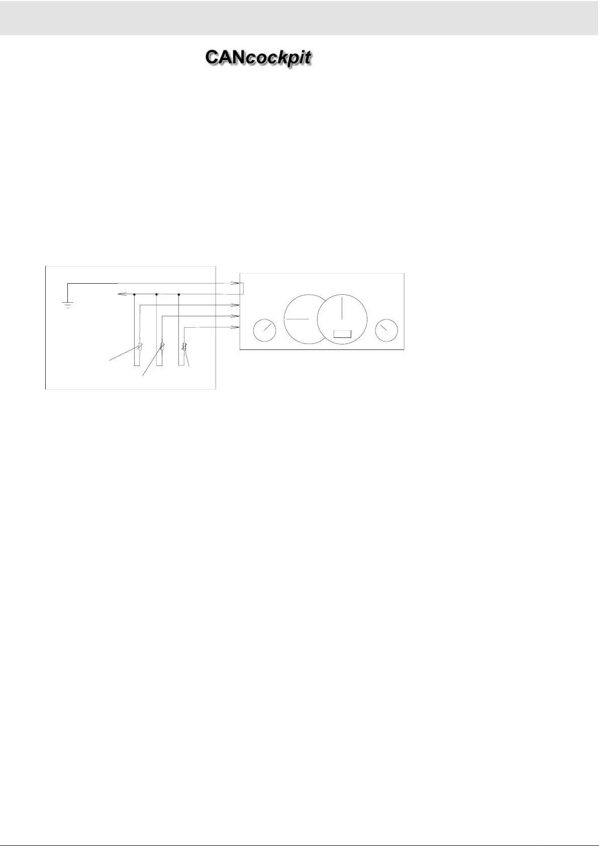
2.3.1.1 Grounding Concept
The Master gauge has two main ground lines. Ground term.31 is connected to the vehicle's body (negative battery terminal)
and Sensor Ground is supplied from the instrument; insulated return sender are necessary. The Sensor Ground should not be
connected to vehicle ground, which would result in a higher current flowing through this line and thus produce a signal noise
and measurement error. Sensor Ground and Ground term.31 are joined together inside the Master Gauge. This grounding
principle is necessary to accurately measure analog values. Ground shift on Sensor Ground is minimized by this concept.
2.3.1.2Sensors
The static and dynamic voltage drop of the sensors should not exceed 0.5 V.
Pressure: 10 - 184 Ohms
Temperature: 10 - 700 Ohms
Fuel lever type: 3 - 180 Ohms
Fuel dip-pipe: 0.5 - 90 Ohms
Other sensors: 4 - 20 mA
Other sensors: 0 - 5 V
2.3.2 Input Signal Processing applied to the two frequency inputs
Frequency 1:
The standard modules can be changed to 500 < k < 400 000 pulses/km or miles for the Speedometer
and 0.5 - 400 pulses/rev for the Tachometer.
Maximum frequency is 40 kHz (2 kHz via internal divider).
Frequency 2 as Hall Sensor / Terminal W:
500 < k < 65000 pulses/km or miles for Speedometer and 0.5 - 65 pulses/rev for Tachometer.
Maximum frequency is 2 kHz.
2. Functional Specification
Product Manual
Technische Änderungen vorbehalten Technical details subject to change
2 - 7
TU00-0726-0000002
0609
,
Fuel
Sender
Oil Pressure
Sensor
Engine-
Temperature
Vehicle
Sensor-Ground
Chassis GND
Gauge2000 System
Ground Term.31
CANcockpit System
Page 18
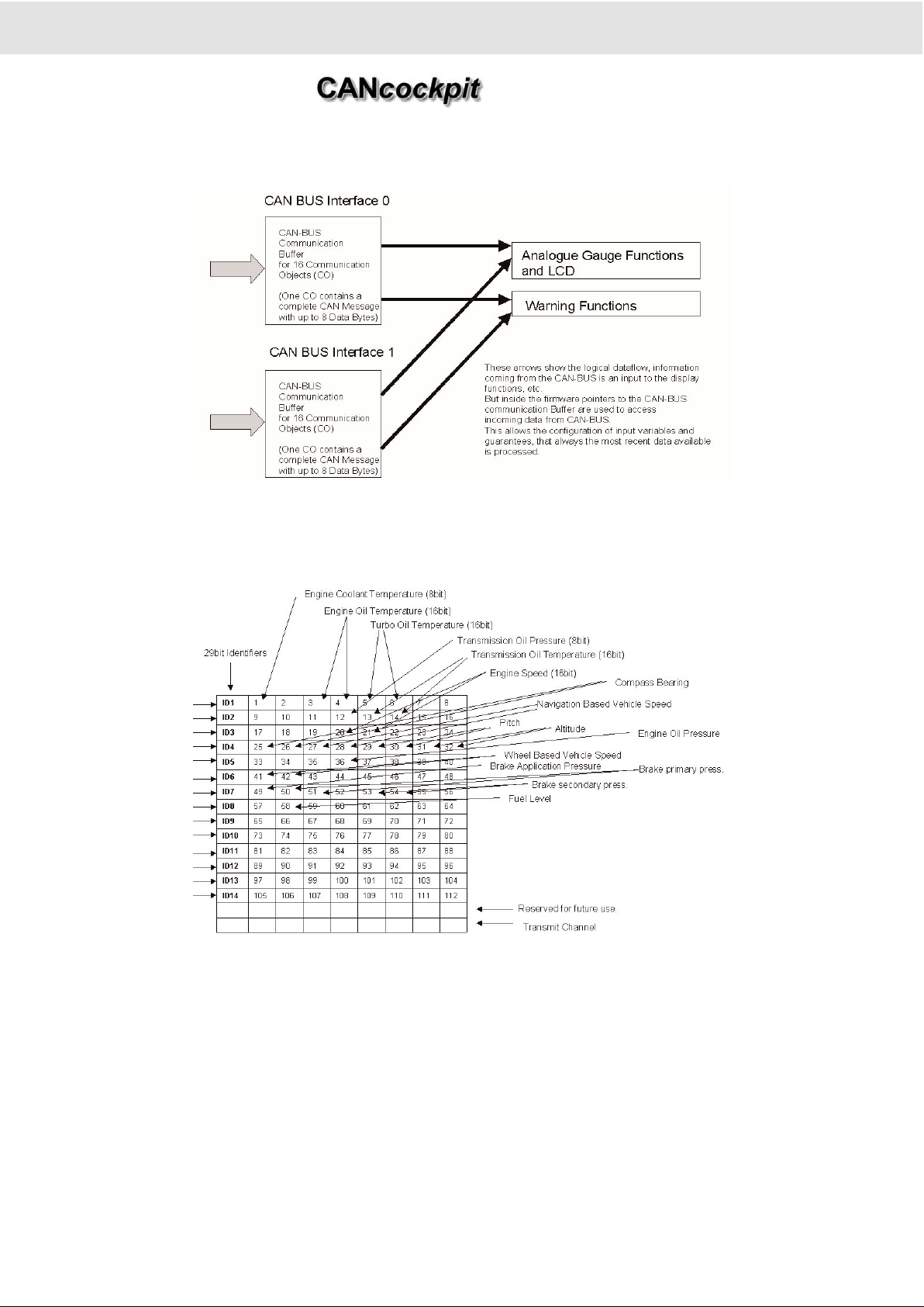
2.3.3 Input Signal Processing for CANbus messages
Example of SAE J1939 Messages received on one of the two CANbus Interfaces.
The Master Gauge CANbus interface conforms to CAN 2.0B specification and supports extended (29Bit) identifiers. The
Gauge acts as a "Standard ECU, which is non-configurable as defined in SAE J1939. The application layer is based on SAE
J1939/71 Rev 2008-01.
Additional communication protocol is CAN Open
For this the different CANbus data bases will be provided by the WINgauge configuration.
2. Functional Specification
Product Manual
Technische Änderungen vorbehalten Technical details subject to change
2 - 8
TU00-0726-0000002
0609
Page 19
Technische Änderungen vorbehalten Technical details subject to change
2 - 9
TU00-0726-0000002
0609
2.4 PIN Assignment Description
Master:
2.4.1 Technical Description
PIN 1: Power Supply (terminal 30)
V
Batt
= + 10,5 V to + 32 V
The instrument is supplied with permanent power through this terminal. Current consumption varies depending on the instruments operating mode (standby or active) and number of Slaves.
PIN 2: Ground (terminal 31)
Power ground of the instrument.
PIN 3, 4: CANbus Interface 1
High-Speed Full CANbus V2.0B compatible (10, 20, 50, 125, 250, 500 kbit/s, 1 Mbit/sec.).
12 V and 24 V system compatible.
Cable: shielded, twisted pair with a drain.
Cable Impedance: nom. 120 Ω.
Topology: linear Bus
Trunk Length: max. 40 meters
Drop Length: max. 1 meter
Termination: 2 resistors 120 Ω at each end of the bus.
Related documents: ISO 11898, SAE J1939/11
U
A combination of 29 bit ID and 11 bit ID can`t be processed!
PIN 5, 6: CANbus Interface 2
See on CANbus Interface 1.
PIN 7: Not connected
PIN 8: K-Line Diagnostic Interface
Programming of the EEPROM and the diagnostics carried out via serial diagnostic interface K-Line.
PIN 9, 25: Analog Input 1
Range: 0.5 - 200
Ω
Standard sensors: Tube-type Sensor: 0,5 Ω to 90 Ω
Lever-type Sensor: 3 Ω to 180 Ω.
Sensor has to be connected between theese pins.
PIN 10, 25: Analog Input 2
2. Functional Specification
Product Manual
Pin Description Pin Description
1 Power Supply (terminal 30) 14 + 8 V DC for sensor supply
2 Ground (terminal 31) 15 0 - 5 V DC Input
3 CAN1 _High 16 Illumination (terminal 58 (d))
4 CAN1 _Low 17 Ignition (terminal 15)
5 CAN2 _High 18 Frequency Input 2 (0-2 kHz)
6 CAN2 _Low 19 Frequency Input 1 (0-40 kHz)
7 NC 20 Switch-Output_1
8 k-Line 21 Switch-Output_2
9
Analog Input 1 (0,5 - 200 Ω)
22 NC
10
Analog Input 2 (0,5 - 300 Ω)
23 NC
11
Analog Input 3 (10 - 700 Ω)
24 External Switch
12 4 - 20 mAInput 25 Analog GND
13 4 - 20 mAGND 26 Frequency GND
Page 20

Range: 0.5 - 300 Ω
Standard sensors: Pressure sensor(10 - 184 Ω)
Sensor has to be connected between theese pins.
PIN 11, 25: Analog Input 3
Range: 10 - 700
Ω
Standard sensors: Temperature sensor (38 - 700 Ω)
Sensor has to be connected between theese pins.
PIN 12, 13: 4 to 20 mA Input
Range: 4 to 20 mA
A resistor converts the 4 - 20 mA current into proportional voltage. Results are sampled every 31.25 msec by the
Microprocessor.
PIN 14: +8 V sensor power supply:
Voltage: +8 V - 0 %, +10 %
Max. current: 50 mA
U
This output can be used only at 24 V power supply.
PIN 15: 0 - 5 V Input :
Range: 0 - 5 V
Results are sampled every 31.25 msec by the Microprocessor.
PIN 16: Illumination Input (terminal 58 (d):
Range: 0 to U
Bat.
(battery voltage)
Dimming of Master gauge illumination and attached Satellite gauges is controlled by the voltage amplitude at the Illumination
input.
PIN 17: Ignition (terminal 15)
Vign.= + 10,5 V to + 32 V
The Microprocessor senses the voltage at the input and turns it into active mode, if the ignition is turned on.
PIN 18, 26: Frequency Input 2
Hall Sensor and terminal W:
Max. Frequency: 2 kHz
U high min.: 5 - 7 V according to the configurated pulses
Signal type: square, sinus
Max. offset: 0.5 V
Off current max.: 100 µA
Duty cycle: 50 ± 15 %
Pulse ratio: 500 - 65 000 pulses/km or miles
Pulse/rev: 0.5 - 65 pulses/revolution
The Instrument has a pull-up resistor at the ignition in the input circuit. Input can be either road speed or engine speed.
Selection by configuration.
U
Only one frequency input (either Input 1 or 2) can be defined as road speed input.
PIN 19, 26: Frequency Input 1
Universal Frequency Input
Max. Frequency: 40 kHz (2 kHz via internal divider, 1:1; 1:2; ... 1:20)
U
high
min: 1.5 - 10 V according to the configurated pulses
Signal type: square, sinus
Max. offset: 0.5 V
Off current max.: 100 µA
Duty cycle: 50 ± 15%
Pulse ratio: 0.5 - 400 pulses/revolution
The instrument has a pull-up resistor at ignition in the input circuit. Input can be either road speed or engine speed. Selection
2. Functional Specification
Product Manual
Technische Änderungen vorbehalten Technical details subject to change
2 - 10
TU00-0726-0000002
0609
Page 21
by configuration. An adjustable frequency divider reduces input frequency, so that it can be processed by the Microprocessor.
U
Only one frequency input (either Input 1 or 2) can be defined as road speed input.
PIN 20: Switch Output 1
Maximum voltage: 32 V
Maximum current: 0.5 A
Warning lamp to be connected between output and supply voltage (terminal 15 or terminal 30).
Switch output controlled by the Microprocessor. The pin turns the output either on or off (static). The output is an open drain
and acts like a low switch to ground.
U
Save against high current with a Fuse 0.5 A!
PIN 21: Switch Output 2
Identical with Switch output 1
PIN 22: Not connected
PIN 23: Not connected
PIN 24: External Switch
Switch has to be connected between this pin and GND
Satellite
PIN 1-3: Satellite Bus Interface (Satbus):
Bus signal levels: 5 V ± 10%
Ground reference: ± 100 mV
Max. Bus length: 10 m
Cable impedance: Standard cable
Connector: 4-Pin MATE-N-LOK AMP
Satbus is used in a Master-/ Slave-configuration and is bi-directional with half-duplex communication. When the system is active, a constant clock signal is produced on the bus by the Master gauge.
Bit-rate on Satbus = 31.25 kHz.
2. Functional Specification
Product Manual
Technische Änderungen vorbehalten Technical details subject to change
2 - 11
TU00-0726-0000002
0609
Pin Description Pin Description
1 - 3 GND
2 Satellite - Bus 4 Power Supply
Page 22
2.5 Display Functions
Five main display functions have been specified for the Master gauge. (s. picture below) As the number of displays in each
main function is configurable (except for odometer and hourmeter), the actual number of displays can be up to a maximum of
146.
A maximum of 30 Warnings and 30 Alarms can be set. The Physical Values of the defined Satellite gauges can be shown on
the display (if configured). Atotal of 25 physical value Displays (PVD) are possible, including the physical values inidcated by
the Satellite gauges. Thus with increasing numbers of Slaves defined by WINgauge, the number of freely selectable physical
values to be displayed on the dot-matrix decreases.
2.5.1 Navigation through Display
The order of the display groups is: Odometer / Hourmeter, Alarms, CAN DTCs, Service Messages, Physical Values, Warnings
and then back to Odometer / Hourmeter. The Alarms, CAN-DTCs, Service Messages and Warnings are being monitored and
appear only if they are activated. If the button is pressed more than 2 sec., the LCD shows the main display which is
Odometer / Hourmeter.
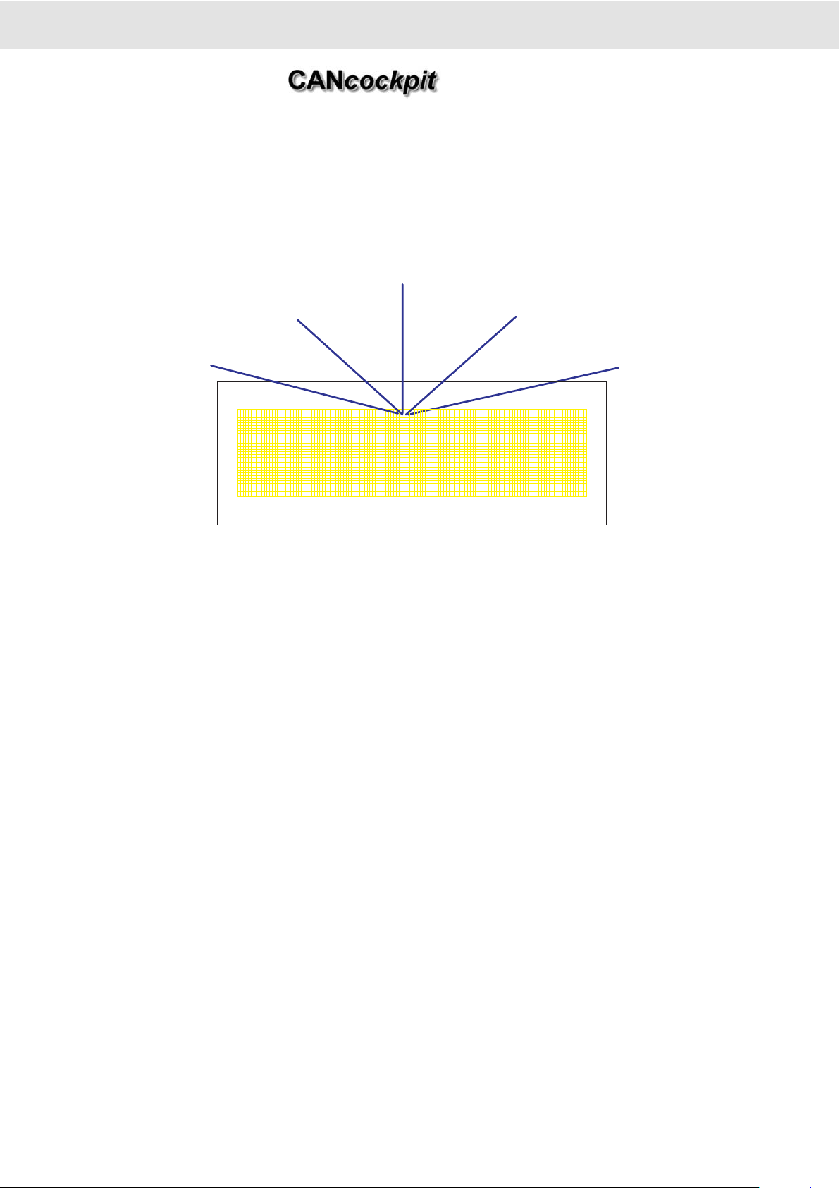
2.5.2 Display Layout
The Dot-matrix Display has 132 x 33 dots.
The following picture shows the proposed display layout. The outer line represents the LCD glass and the inside marks the
active display area. The structure inside has only been drawn for illustration; it is not visible on the display itself
2. Functional Specification
Product Manual
Technische Änderungen vorbehalten Technical details subject to change
2 - 12
TU00-0726-0000002
0609
1. Odometer
Hourmeter
2. Physical V alues
Display (max. 25)
3. Se rv ic e In te rv a l
Message (max. 15)
4. CAN Diagnostic
Trouble Codes (max. 5)
5. Warning and Alarm
Messages (max. 30)
45)
60)
Page 23
Technische Änderungen vorbehalten Technical details subject to change
2 - 13
TU00-0726-0000002
0609
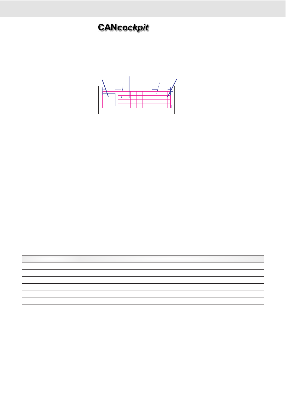
The display is structured into three main areas:
1. Symbol Area
This 30 x 32 pixel area is reserved for graphic symbols. The symbols are left aligned to optically enlarge the appearance of
the symbol.
2. Central Area
The centre of the display is organised as one or two lines with 6 digits each. Here it is possible to show alphanumeric ASCII
characters using the large font (12 x 16 pixel). If only one line is displayed, then this line will be centred in vertical direction.
Short text (up to 6 letters) can be used to provide identification for the value displayed. This area is best suited to communicate important numeric values to the user. Values will be shown in the second line on the right, where units appear on the left.
One or two centre lines are configured via WINgauge as well as the description of the short text.
3. Physical Unit Area
The physical unit area is located right of the alphanumeric Centre Lines. In general the unit belonging to the value displayed
on the centre lines is shown here as text. This area is organised as four lines of 5 characters of the small font. If the Unit can
be displayed with less than three ASCII characters, then the large font is applied, else the small font is used. Units will not be
wrapped into the next line.
If there are two Centre Lines, then there will also be two-unit Lines (small Line 2 and Line 4). In case only one Centre Line is
displayed, then only one corresponding Unit Line will be visible (small Line 3).
It is therefore possible to show the following parameters and units to give a clear indication of the valid physical unit which
can be chosen via WINgauge:
2. Functional Specification
Product Manual
24 * 24
12 * 16
6 * 8
30 dots
72 dots
30 dots
32 dots
Dot Matrix Layout
One centre Line or
optional two Alphanumeric Lines
with 6digits (12*16dots) each
Four Alphanumeric
Lines with 5 digits each
Graphic
Symbol Area
Parameter Units
Revolution / rotation 1/min, rpm
Speed km/h, mph, knots
Distances km, m (Meter), mm, miles, mi, M, m (landmile = 1.609 km), nm (nautical mile = 1.852 km)
Power supply Volt, V, A, mA
Time h, hours, min, sec
Temperatures °C, °F
Pressures bar, psi, kPa, Mpa,
Level of liquids %, l, gal (US-gallons)
Fuel consumption l/h, gal/h, km/l, l/100, kg/h, km/kg
Weight kg
Power N, kN, Nm
Diverse Ohm, Grad, deg, appl, Count, qm/h, Gear, Code, SPN, FMI
Page 24
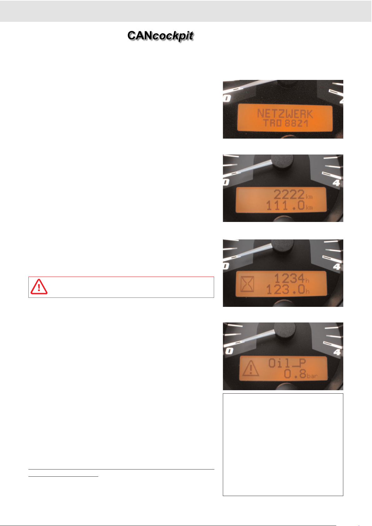
2.5.3 Display Functions
2.5.3.1 Main Display (Odometer, Hourmeter)
The display shows total and trip in two lines. Total has 6 digits and trip has
4 plus 1 digit. The figures roll over to 0.0 after a distance of 999.999 /
9.999 or 100.000 / 1.000 hours. Pressing the button longer than 2 seconds
will reset trip odometer or hourmeter.
A part of the Display can be used to show the company logo as a start-up
display configured by WINgauge
The centre of the display shows the value of the odometer in the first line
and the tripmeter underneath. The physical unit is displayed right to it and
can be either miles or km.
The main display of the tachometer is similar to the speedometer, except
that it shows operating hours instead of odometer and trip meter.
The physical unit is "h" for hours. The digit after the decimal point of the
trip hourmeter shows 1/10h.
if no CAN signal is received, only dashes will be indicated.
2.5.3.2 Alarm Display
If an alarm is triggered the Alarm Display is shown. To alert the user, the
General- Alarm-Symbol is flashing, alternating with the symbol that indicates the type of alarm.
The Central area of the display shows the actual physical value (6digits).
The physical unit appears to the right.
When the customer quits the alarm longer two seconds the Display will
change to the last displayed value (if no other Alarm and Warning is existing which weren't quitted). The General Alarm Symbol will remain in the
graphic Symbol Area with a vertical line on the right side of the symbol to
indicate that the Alarm doesn't correspond to the main display but to another Physical Value.
When different Alarms are present the highest priority will be shown. The
priority of the alarms is defined with the WINgauge Software. If the Alarm
is confirmed and the Alarm condition does not exist anymore then the
Alarm is cleared in the list of active Alarms. If the Alarm is not confirmed
but the Alarm conditon does not exist anymore then the Alarm is still in the
list of active Alarms.
T
o see the different Alarms in the Alarm display group the button has to be
pressed shortly (>50 msec).
2. Functional Specification
Product Manual
Main Display for Tachometer
Physikal
Unit
6 Digit Hourmeter
+ Triphourmeter
Main Display for Speedometer
Physikal
Unit
6 Digit Odometer
+ Tripmeter
Alarm Display
Alternating
ISO Symbol
6 Digit
Label
6 Digit Value
Configuration Option:
• To provide additional information two
Centre Lines can be programmed. The
top line displays a label for identification.
• If no physical value should appear on the
display, then a configuration allows a display, which only shows the alternating
graphic symbol in the centre of the display.
This option is useful, if a digital input triggers
an alarm.
Technische Änderungen vorbehalten Technical details subject to change
2 - 14
TU00-0726-0000002
0609
Physikal
Unit
Page 25
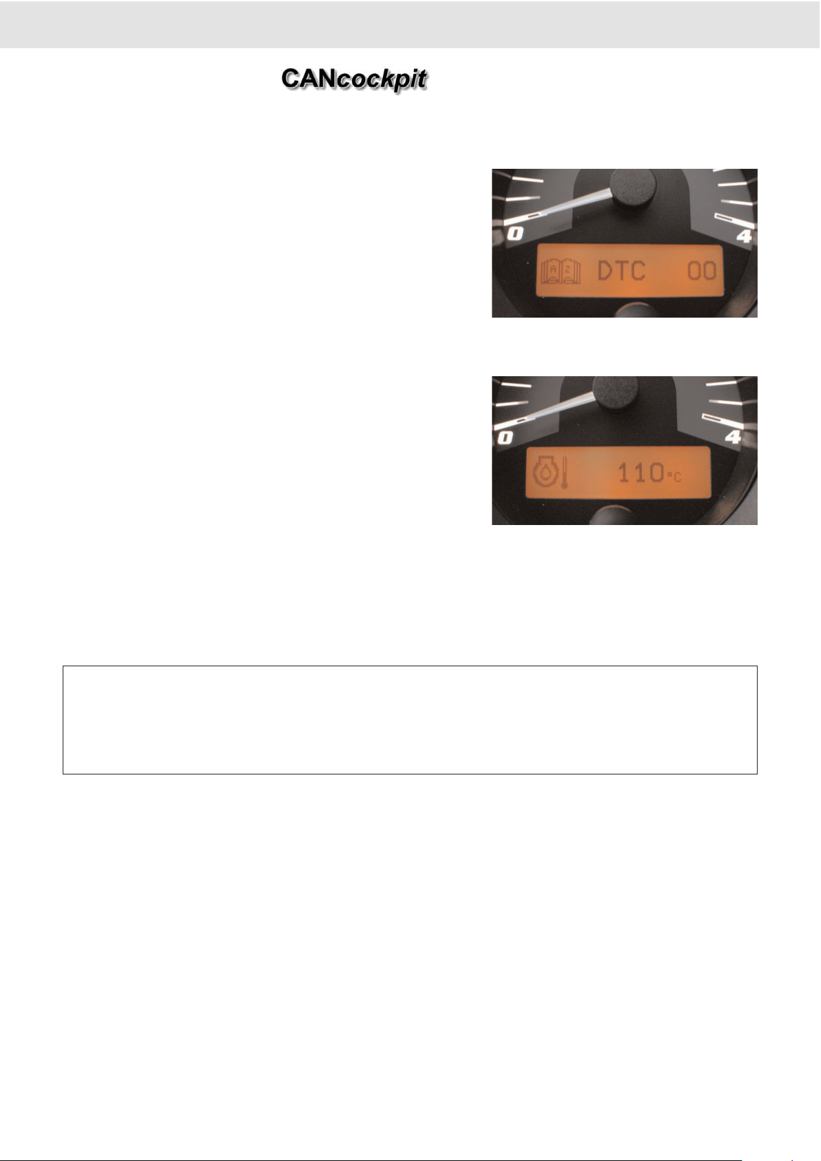
2.5.3.3 CAN DTC Display
1 to 5 independent DTC channels can be configured. Every channel is
able to receive the DTCs from one CAN device (Source Address).
If DTCs are received from any of the configured CAN devices, they will be
stored into a DTC receive buffer. The buffer will be able to hold a total of
40 DTCs and will be implemented as a ring buffer, so that old DTCs can
be overwritten by newly received DTCs
2.5.3.4 Warning Display
In the Warning display the Specific Graphic Symbol (ISO) is flashing at 1
Hz. There is no alternating.
The operator can acknowledge the Warning by pressing the button longer
than two seconds. The Display will change to the Display, which was active before, if no other Alarms and Warnings are existing, which have not
been acknowledged yet.
When different Warnings are present the highest priority will be shown.
The priority of the Warnings is defined with the WINgauge Software.
Alarms have higher priorities than the Warnings. If the Warning condition
vanishes also the Warning will vanish, if it has been acknowledged.
To see the different Warnings in the Warning display group the button has
to be pressed longer than 50 msec.
2. Functional Specification
Product Manual
CAN DTC Display
Symbol for
CAN DTC
Position in
Ring Buffer
6 Digit
Message Label
Warning Display
ISO Symbol
Physical
Unit
6 Digit Label
Configuration Option:
• To provide additional information two Centre-Lines can be programmed. The top line displaying a label for identification.
• If no phsyical value should appear on the display, then a configuration allows a display, which only shows the flashing
graphic symbol in the centre of the display.
• This option is usefull, if a digital input triggers a warning.
Technische Änderungen vorbehalten Technical details subject to change
2 - 15
TU00-0726-0000002
0609
Page 26
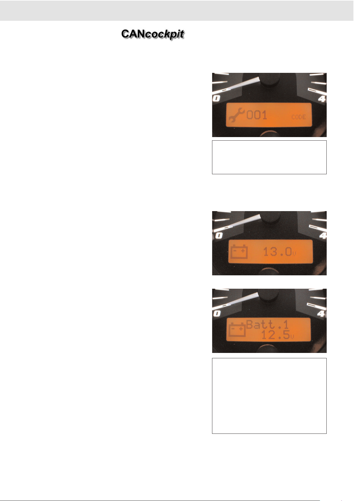
2.5.3.5 Service Message
The Service Message indication is based on operating hours and odometer.
The Graphic Symbol Area displays the "Service Symbol" in case a Service
Message becomes due.
The corresponding service code is shown on the centre line of the display
centre. As a "unit" the word "CODE" appears to indicate, that the value is a
code number.
To see the different active Service Messages in the Service Message display group the button has to be pressed longer than 50 msec.
2.5.3.6 Physical Value Display
The graphic display area shows a symbol relating to the physical value displayed. The symbol can be selected via configuration from the defined
symbols in ROM or EEPROM.
In the standard form the physical value is shown on a single Centre-Line,
followed by the physical unit. This unit text can be selected from ROM during configuration.
If the value is outside of the configurated range, then "------" is
shown.
To see the different Physical Values in the Physical Value display group
the button has to be pressed longer than 50 msec
2. Functional Specification
Product Manual
Service Message
Service
Symbol
Service Code
Configuration Option:
The Service Message indication can be configured as stand- alone or interval message.
Physical Value Display
ISO
Symbol
Physical value
6 Digit Value
Physical Value Display
ISO
Symbol
6 Digit
Label
6 Digit Value
Configuration Option:
As an option a text label can provide identification for the value displayed. For example
Battery one of two batteries, or Motor-2 of
two motors. The text label can be configured
via WINgauge with maximum 6 letters.
The physical value is displayed in the lower
centre line.
Physical
Unit
Technische Änderungen vorbehalten Technical details subject to change
2 - 16
TU00-0726-0000002
0609
Page 27
Technische Änderungen vorbehalten Technical details subject to change
2 - 17
TU00-0726-0000002
0609
2.5.4 Alarm- and Warning Functions
The Alarms and Warnings are triggered by the input values. Configuration parameters in EEPROM select the input values.
These variables can have a size of 1, 8 and 16 bit. Possible inputs are engine speed, road speed, data in CAN messages
and analogue sensor values. Input values are then monitored and if the configured thresholds are exceeded, then an Alarm
or Warning action is triggered, resulting in switch outputs being activated.
2.5.4.1 Description of the Outputs
Definitions:
Warning: Is a message to make the operator aware of a condition, which requires his attention.
Alarm: Is a message to alert the operator about a condition, which requires his attention and immediate action. The Alarm is
more severe than a Warning.
The switch outputs are only controlled by the Alarm- and Warning Functions.
The following switch outputs are provided:
a. Output 1 and Output 2
These are two outputs, which act like two switches to ground. The switch output can control i.e. a warning lamp, a buzzer or
a relay. It turns off, when the Alarm condition is not existing anymore, or if the Alarm has been acknowledged and it was configured. It stays on, if another Alarm condition also configured to turn on this output is still active.
b. Display
Every Alarm or Warning activates a display on the dot matrix. When the Alarm is triggered, then the associated display appears on the dot matrix, overwriting the previous display. The display combines a graphic symbol with a physical value (numerical value plus physical unit), describing the input value, which has caused the Alarm or Warning.
c. Warning Lamps in the Satellite Gauges
The Satellite Gauges include a warning lamp. This warning lamp can be turned on and off via the Sat-Bus. An Alarm or
Warning could be configured to activate a warning lamp in each of the Satellite Gauges. The selected warning lamp in the
Satellite Gauge remains on as long as the trigger condition remains, and turns off as soon as the trigger condition is not existing anymore. Flashing of the warning lamp can be configurated.
2.5.4.2 Switch Output Acknowledgement Function
The Acknowledgement Function provides a means to turn off some of the switch output action. This may be desired, if the
Alarm activates a buzzer and the operator wants to turn the buzzer off.
To acknowledge a switch output, the operator must press the button for more than 2 sec, while the Alarm or Warning is active.
When a Warning or Alarm has been acknowledged, then the Switch Outputs (1, 2) will be deactivated, if they have been configured to turn off these outputs.
2. Functional Specification
Product Manual
Input Values
CAN Cockpit Plus
Switch Output Functions
Output 1
Output 2
Display
Lamp in SAT-Gauge 0.. 15
Configuration Data
From EEPROM
Page 28
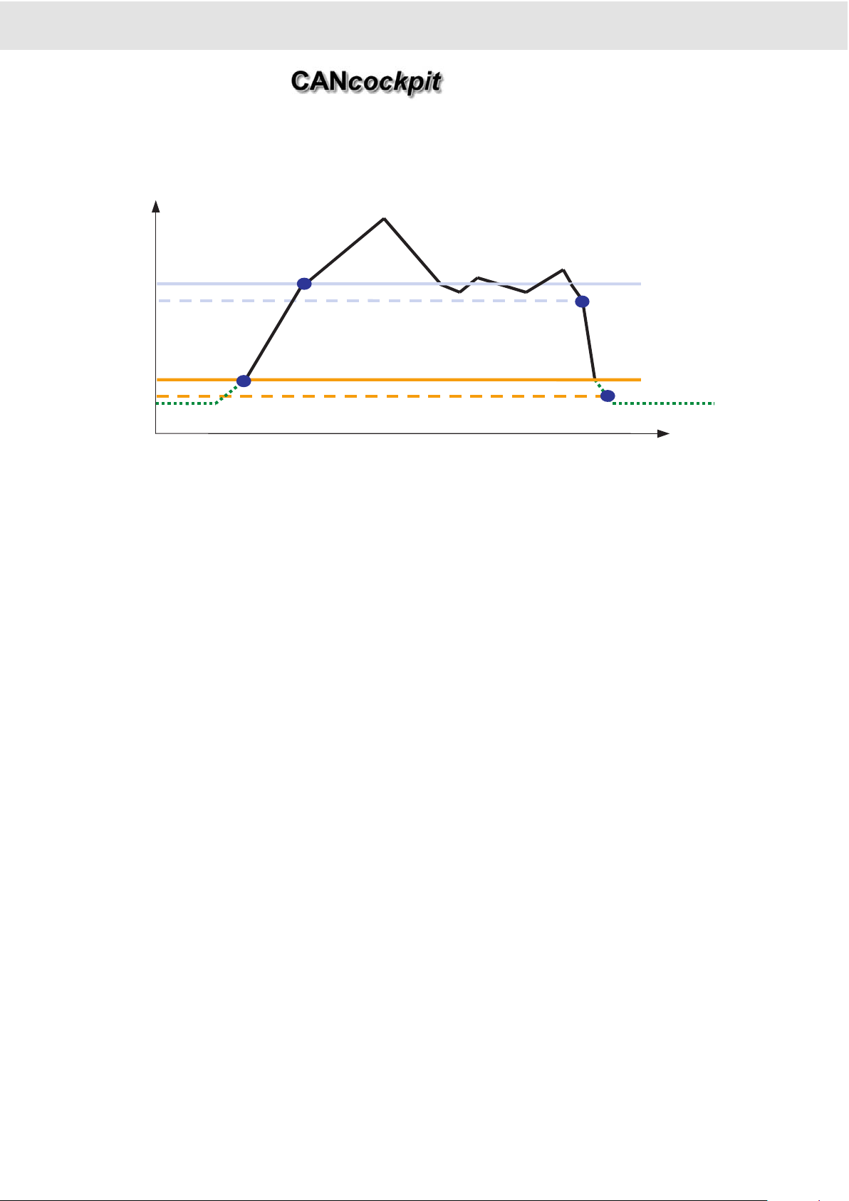
2.5.4.3 Alarm and Warning Trigger Conditions
The diagram above illustrates the Alarm and Warning trigger conditions for the engine coolant temperature as an example.
The Warning threshold is set at 105° C, where the Alarm threshold is reached at 110° C. To prevent repeated on/off cycles of
the Warning or the Alarm an activation hysteresis is applied. Therefore in above example an Alarm is turned off, if the temperature falls below 108° C and the warning is cancelled at 103° C. The hysteresis is 2° C in this case and is the same for both
Alarm- and Warning condition. In addition a turn-on delay from 1 sec to 4 minutes can be configured. The delay time starts,
when the threshold is reached. If the input value falls below the threshold value, then the delay time restarts from this point in
time.
It can be configured, that the Warning is triggered, if a value rises above a threshold (as in the case of the engine coolant
temp.), or if the input value falls below a threshold (e.g. fuel level).
2.5.4.4 Alarm and Warning Trigger enabling with Engine running
Triggering of some Alarms and Warnings only makes sense, when the engine is actually running. Examples are engine oil
pressure or hydraulic pressure. For these situations triggering an Alarm and Warning can be disabled until the engine is running. This conditional trigger enable is selectable for every Alarm and Warning (together) during configuration.
Engine running is detected, by exceeding a separately configurable threshold value: the Alarm and Warning enable engine
speed threshold. The minimum threshold is 0 rpm and the maximum is 32.000 rpm.
An additional trigger-enable time delay starting from engine running condition can be configured. This is helpfull in cases,
where it takes a while until a pressure is built up.
This delay time is settable from 0 to 250 sec with a resolution of 1sec.
2. Functional Specification
Product Manual
T/°C
time/sec
105
103
110
108
Warning
on
Alarm on
Alarm off
Warning off
Technische Änderungen vorbehalten Technical details subject to change
2 - 18
TU00-0726-0000002
0609
Page 29

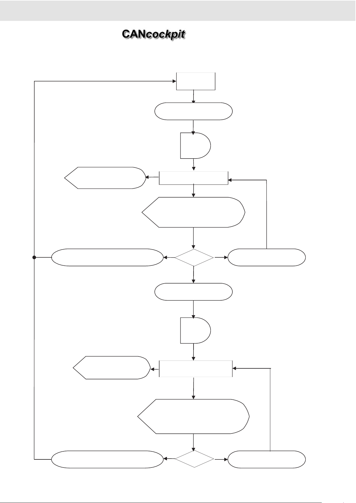
2.5.4.5 Alarm and Warning State Diagram (Maximum Value Algorithm)
2. Functional Specification
Product Manual
VALUE
Warning
Time
delay
Time
delay
Display Warning
Indication *
Alarm
Value > WarnLev el
Value > Alar m Level
Display Alarm
Indication *
Reminder: Alarm li s t and
flas hing Ala r m symbol
and WIN gauge "Alarm
Action"
Re mi nder: Warning list
an d WI Ngauge "Alarm
Action"
?
Value > WarnLev el
Value < WarnLevel - Hysteresi s
Value < Alar m Lev el
?
Value > AlarmLevel + Hysteresis
Technische Änderungen vorbehalten Technical details subject to change
2 - 19
TU00-0726-0000002
0609
Page 30
Alarm and Warning State Diagram (Minimum Value Algorithm)
2. Functional Specification
Product Manual
VALUE
Warning
Time
delay
Time
delay
Display Warning
Indication *
Alarm
Value <= WarnLevel
Value <= AlarmLevel
Display Alarm
Indication *
Reminder: Alarm list and
flashing Alarm symbol
and WINgauge "Alarm
Action"
Reminder: Warning list
and WINgauge "Alarm
Action"
Value <= WarnLevel
Value < WarnLevel - Hysteresis
Value <= AlarmLevel
Value > AlarmLevel + H yster es is
Technische Änderungen vorbehalten Technical details subject to change
2 - 20
TU00-0726-0000002
0609
Page 31

Technische Änderungen vorbehalten Technical details subject to change
2 - 21
TU00-0726-0000002
0609
2.5.5 Service
The Service message is based on the Hourmeter or Odometer.The service message indication can be configured via
WINgauge. There are 15 independent service messages with customer specific settings, which can be configured via
WINgauge. The service messages are implemented as periodic intervals. Amessage which should be indicated only once,
the quantity of intervals would then be 0. Configuration data is stored in EEPROM.
For each of the 15 Service messages following can be specified in a table:
1. Service code number: Range: 1 to 255. 0 needs to be entered to disable this service function.
2. First message after x hours: ( 1h <= x <= 65.000 h )
3. Periodic service time: Range: 1h to 4.095h. If 0h is selected, it means only once (not periodic).
If a Service message has expired, this service code is displayed as a decimal number together with the common service
symbol on the dot-matrix display. The Service message display remains active until this service code is reseted.
2.5.5.1 Reset of Service messages
The reset of the service message function is possible first if it occured and not before.
When a one-time service message will be reseted, then this Service message will be disabled by writing 0 into the service
code field of the Service message table in EEPROM.
When a periodic interval will be reseted then the periodic service time will be added to the hours of the current hourmeter value. This will ensure, that even if a Service message is reseted later than required, the time to the next service indication will
be the periodic interval time as specified.
Example: Service message No.: 12
Service code: 153
First service after: 300 h
Periodic service:100 h
The reset of the Service message is part of the system check function (part of safety check).
Procedure for resetting a Service message:
1. With ignition switched off, push the button and hold down while ignition is being turned on, then the system check function
is activated and clears the contents of the DTC List.
2. If there are any service messages active, then they will be displayed on the Dot-Matrix Display starting with the first active
service message. If the button is then pressed and held for 5 seconds or longer, then this Service message will be reseted. The next active Service message is displayed afterwards. To proceed to the next active service message without resetting the displayed code the button needs to be pressed shortly (<5 sec). If all active service codes have been displayed, then the system check function is started.
2. Functional Specification
Product Manual
Event Time (hourmeter) Display
First service code displayed after 300 h 153
Reset of this service at 340 h
Next service display at 440 h 153
Page 32

2.5.6 CAN (SAE J1939) DTC (Diagnostic Trouble Codes) messages
It will be required to know the CAN source address (SA) of the controller (ECU), which has sent a DTC message, so that the
problem can be located.
The SAE J1939 specifies 13 different diagnostic modes (DM1 to DM13). But for CANcockpit only DM1 is relevant.
In DM1 active DTCs are broadcast on the CAN-Bus. Active means, that these faults are existing at the moment, compared to
faults, which existed sometime in the past.
2.5.6.1 CAN SAE J1939 Elements
DTCs consist of 4 elements defined in SAE J1939:
1. Suspect Parameter Number (SPN) 19 bits
In the DTC, the SPN identifies the faulty element, component, sensor or parameter of a device (ECU).
2. Failure Mode Indicator (FMI) 5bits
The FMI defines the type of failure detected. It provides additional information about the nature of the fault. There are 32 predefined FMIs.
Examples are:
"Out of calibration", "Data Valid but above normal operational range", "Mechanical System not responding or out of adjustment"….
3. Occurrence Count (OC) 7bits
Shows the number of times a fault was active
4. SPN Conversion Method (CM) 1bit
The February 1996 version of SAE J1939-73 contained inadequate definitions to assure consistent implementations.
Consequently the specification of the DTC format was changed. To indicate the new consistent format this bit must be set to 0.
Also the old versions will be supported by CANcockpit.
The number of possible DTCs is very large, therefore efficient filtering is important for this function.
There are two main applications for DTCs (Diagnostic Trouble Codes):
• To inform the operator, that something is not as expected.
Depending on the DTC it can have the nature of an Alarm (most severe), Warning or only Information
• To provide diagnostic information for the workshop, so that system faults can be analyzed and repaired.
2. Functional Specification
Product Manual
DTC
Data Byte 3
8 least significant bits of SPN
Data Byte 4
8 medium significant bits of
SPN
Data Byte 5
3 most significant bits of SPN
plus 5 bit FMI
Data Byte 6
Conversion Method bit plus 7
bit Occurrence Count.
Technische Änderungen vorbehalten Technical details subject to change
2 - 22
TU00-0726-0000002
0609
Page 33

2.5.6.2 CAN DTC Information Display Requirements
1. Information for the operator needs to be brief and clear, so that action can be taken quickly, if required.
• Activate Warning Lamp
• Activate Switch-Output
• Display Short Text
2. For the workshop it is more important to get detailed information, so the cause can be found and fixed.
• DTC List with SPN, FMI and Occurrence Count
The DTC List can also be viewed by the operator, but requires detailed knowledge of the CAN devices reporting the DTCs.
Also it can be expected, that the workshop will have other diagnostic tools, which can access even more Information than
J1939 DM1.
2.5.6.3 CAN DTC Display Functions
2.5.6.3.1 DTC Reception
0ne to five independent DTC channels can be configured. Every channel is able to receive the DTCs from one CAN device
(Source Address).
If DTCs are received from any of the configured CAN devices, they will be stored into a DTC receive buffer. The buffer will be
able to hold a total of 40 DTCs and will be implemented as a ring buffer, so that old DTCs can be overwritten by newly received DTCs.
Every newly received DTC will be compared with latest DTC`s in the ring buffer. If they are different it will be stored in the ring
buffer. Thus avoid overflowing of the ring buffer by toggling transmitted DTC`s.
2.5.6.3.2 DTC List
If the service personnel or the operator wants to check for received DTCs, he can step through the display list until coming to
the DTC-Displays. There will be no automatic display, which comes up and must then be acknowledged. Therefore it is possible to prevent annoying displays coming up, if DTCs are received, which have no actual relevance.
The DTC List function will provide access to the DTCs inside the DTC receive buffer. One DTC Display will exist in the display list for every configured DTC channel (channel 1 to 5).
To see the received DTCs of one channel the operator presses and holds the button for longer than 2sec. At this time the processor will transfer the received DTCs from the DTC Receive Ring Buffer to the DTC List. Only the DTCs of the selected
channel will appear in the DTC List. The most recent DTC will be shown first. Every short press will lead to earlier received
DTCs, until all DTCs have been shown or the button is pressed and held for more than 2sec.
The DTC List will be cleared at ignition off/ on (configurable).
2. Functional Specification
Product Manual
Technische Änderungen vorbehalten Technical details subject to change
2 - 23
TU00-0726-0000002
0609
Page 34

2.5.6.3.3 DTC List Display Format
One Graphic Symbol per DTC Channel (Source Address) can be configured and will be shown together with the DTC in the
upper and lower level. It indicates, where the DTC message comes from.
Also the number of received DTC`s on this channel (0-40) which are currently inside the DTC Ring Buffer will be displayed.
Examples:
Electronic Engine Controller (EEC) reports Pre-Filter Oil Pressure
(SPN=1208) was 102 times (occurrence count) above normal operating
range - most severe level (FMI=0).
Index 10 provides information about the position inside the Ring Buffer.
Electronic Engine Controller (EEC) reports System Diagnostic Code #1
(SPN=611), occurrence count information not available (OC=127) and
Special Instructions (FMI=14).
Index 15 provides information about the position inside the Ring Buffer.
Electronic Transmission Controller (ETC) reports Clutch Actuator
(SPN=788) was 2 times Out of Adjustment ((FMI=7)
Index 18 provides information about the position inside the Ring Buffer.
Hydraulic Controller reports Hydraulic Reservoir Temperature (SPN=1508)
one time Above Normal (FMI=3)
Index 40 provides information about the position inside the Ring Buffer.
2. Functional Specification
Product Manual
Technische Änderungen vorbehalten Technical details subject to change
2 - 24
TU00-0726-0000002
0609
Page 35

Technische Änderungen vorbehalten Technical details subject to change
2 - 25
TU00-0726-0000002
0609
2.5.6.3.4 Diagnostic Lamp Status
The following diagnostic lamps are defined in SAE J1939:
1. Red Stop Lamp —> Stop Engine
2. Amber Warning Lamp
3. Protect Lamp
4. Malfunction Indicator Lamp
The status information of all configured DTC received channels are collected and the result will be stored in a 16bit status variable (Byte1 and Byte2). It is then possible to configure alarm or warning functions to react on the diagnostic lamp status.
This also has the advantage that normal Alarm- or Warning-Functions are integrated with Alarms or Warnings (DTC Lamp
Status) from the CAN Bus.
2.5.6.3.5 DTC Scan
When DTC`s are received via interrupt, they are immediately stored into the DTC-receive ring buffer. This ring buffer will then
be scanned for 8 specific DTC`s. These DTC`s can be configured via WINgauge with unique icons and labels. Alarm and/ or
Warning Functions can then be configured to trigger on the status of certain bits inside the DTC scan result register.
2.5.6.4 Speedometer Master Gauge
2.5.6.4.1 Tolerance
The overall speedometer accuracy is within 0% to +4% of full scale reading for each indicated value over the operating range
of the instrument.
This fulfills SAE J1226 for the American market and for the European market DIN 75521-2.
2. Functional Specification
Product Manual
SAE J1226 DIN 75 521 - 2
-4% 4% 0 <= v1-v2 <= v2/25 + 5km/h
Actual speed u. Tol. o. Tol. u. Tol. o. Tol.
0 0 0
10 9 ,6 10,4
20 19,2 20,8
30 28,8 31,2
40 38,4 41,6 40 46,6
50 48 52 50 57
60 57,6 62,4 60 67,4
70 67,2 72,8 70 77,8
80 76,8 83,2 80 88,2
90 86,4 93,6 90 98,6
100 96 104 100 109
110 105,6 114,4 110 119,4
120 115.2 124.8 120 129,8
Page 36

2.5.6.4.2 Speedometer Gauge Operation
The Master gauge receives speed information either via CAN or via one of the frequency inputs. During configuration the
source of the speed information has to be defined. The input signal is first converted into a physical speed value. The microcontroller calculates the deflection angle of the speedometer based on this physical speed value and gauge output characteristic.
Specification of odometer storage
The standard Speedometer version of the Master gauge contains an Odometer. It can be configured that also the Tachometer
can have an Odometer instead of an Hourmeter. The Odometer consists of a total Odometer and a Tripodometer. Both can
be displayed on the dot matrix LCD as two lines. Format is 6 digits for total km, landmiles, nautical miles or meter and 4 digits, decimal point and 1 digit for 1/10 kilometer, land mile or nautical mile. The resolution of meter is 1m.
a. Information comes from CAN-Bus Interfaces (one of two):
For the Odometer indication it must be ensured that a ECU is broadcasting this information on the CAN-Bus. If no signal is
received only dashes will be indicated.
b. Total odometer information generated by master gauge:
The Odometer information will be written to EEPROM every 1km. Aring counter algorithm is applied to save and recover the
information from EEPROM. The rest-distance is written to EEPROM 10 sec after ignition has been turned off.
A special 16-word-ring-counter algorithm is applied to recover the odometer in case the battery was disconnected.
With nominal input frequency applied, the odometer shall indicate calculated mileage within ± 0.3% [SAE J1226].
2. Functional Specification
Product Manual
Technische Änderungen vorbehalten Technical details subject to change
2 - 26
TU00-0726-0000002
0609
Page 37

2.5.6.5 Tachometer Master Gauge
2.5.6.5.1 Tolerance
The Tachometer indication must be within ± 2% of full scale with nominal voltage applied at temperature of 24 ± 3° C. [SAE
J1399].
2.5.6.5.2 Tachometer Gauge Operation
The Master gauge receives the engine speed information either via CAN-Bus or via one of two frequency inputs. During configuration the source of the engine speed information has to be defined. The input signal is first converted into a physical engine speed value. The micro-controller calculates the deflection angle of the Tachometer.
2.5.6.5.3 Specification of the hourmeter
The standard Tachometer version of the Master gauge contains an Hourmeter. It can be also configured with the WINgauge
that also the Speedometer can contain an Hourmeter.
U
Legal demands are to fulfil!
a. Information comes from CAN-Bus Interfaces (one of two):
For the Hourmeter indication it must be ensured that a ECU is broadcasting this information on the CAN-Bus. If no signal is
received only dashes will be indicated.
b. Total hours information generated by master gauge:
The Hourmeter counts the number of engine hours, when the engine speed exceeds a threshold value configurable via
WINgauge (default value 300 rpm). If the engine speed is below the threshold value the hour counting stops (total and trip).
The last value willI be stored within 10 sec in EEPROM after the ignition is turned off, then counting stops, no matter if the engine is running or not.
The time indication is within + 5 sec with nominal voltage supplied at 25 degrees C and within + 10 sec with nominal voltage
supplied over the full operating temperature range.
The total hour information is backed-up in EEPROM every 7.5 minutes. Aspecial 16-word-ring-counter algorithm is applied to
recover total hours in case battery had been disconnected.
2. Functional Specification
Product Manual
Technische Änderungen vorbehalten Technical details subject to change
2 - 27
TU00-0726-0000002
0609
Page 38

3. Satellite Gauges
3.1 Mechanical concept
The movements are front mounted stepper motors SM2, only clockwise indication.
Connectors: AMP 6 Pin MATE-N-LOK
The dials have a 240° scale and a black panel effect for the warning lamps, so without activating of the warning lamp no sign
is visible.
3.2 Fault modes
When ignition is off, the pointers are positioned 6° below the left side of the scales. With ignition on the pointers are moving to
the scale start value. When the gauges receive wrong informations or the analog signals are out of range (configured by
WINgauge), the pointers are moving 6° below the scale start value
2. Functional Specification
Product Manual
Technische Änderungen vorbehalten Technical details subject to change
2 - 28
TU00-0726-0000002
0609
Page 39

Technische Änderungen vorbehalten Technical details subject to change
2 - 29
TU00-0726-0000002
0609
3.3 Satellite gauge address
Each Satellite has his fixed address. The address is defined with the Assy PCB.
The matrix of the combination of the gauge type and address:
U
Maximum 16 Satellite gauges can be connected per Master. To avoid grave system conflicts, on each address
is only one gauge allowed.
3.4 Warning Lamp inside the Satellite Gauge
All warning lamps are red except the amber level warning lamps. The WINgauge allows configuration of these warning lamps.
3.5 Tolerance
The Satellites have the pointer accuracy of ± 2.5%.
2. Functional Specification
Product Manual
Address Numbers of the Satellite gauges
00 Speedo / Tacho 1
01 Pressure Engine Oil
02 Pressure Brake 1 / Rudder / Primary air
03 Pressure Transmission Oil
04 Pressure Turbocharger / Tacho 2
05 Temperature Engine Oil
06 Temperature Transmission Oil
07 Coolant Water Temperature
08 Temperature Hydraulics Oil
09 Temperature without Symbol / Gear Oil
10 Pyrometer / Pressure Brake 2 / Turbo / Exhaust
11 Level, Fuel level 1
12 Level, Fresh Water / Cylinder Head / Position Rear Wheel
13 Level, Waste Water / Fuel Level 2 / Pressure Brake 2 (250 bar) / AddBlue / Winch
14 Voltmeter
15 Hydraulic Pressure / Ammeter / Pressure Brake 1(250 bar)
Page 40

A. Technical Data
Operating Temperature
Operating Temperature: -40°C to + 85°C (at nominal voltage)
Visible restrictions: for LCD outside -20°C and +70°C
Storage Temperature
Storage temperature: -40°C to +85°C
LCD Humidity resistance: +65°C ± 2°C
+2
90% r.F. -3%
Supply Voltage
Nominal Voltage: + 12 V and + 24 V
Operating Voltage: + 10,5 V to + 32 V as standard
Test voltage: + 14 V and + 28 V
Total Supply Current: 200 mA ± 20% for Master and 110 mAper Satellite
Satellite supply: + 10,5V to + 32V, current consumption max. 2 A
Sensor supply: + 8 V ± 10% (8 V - 0%, +10% at 24 V), Imax: 50 mA
Ground is connected to the negative battery terminal.
Idle Current
The Ignition off current (stand by mode) is 4 mA for the System (Master and Satellites).
Ground shift
Ground shift on non-analogue inputs are assumed to be < ± 0.5 V.
i.e. all digital input have to work with an additional signal offset of ± 0.5 V
EMC Requirements
See enclosures
Overvoltage Protection
The Master can withstand a voltage of 56 V for 5 minutes without damage (SAE J1810).
I/O circuit protection
The gauges are protected against reversed battery polarity.
Cable requirement
To the Master:
Type cross section: 0,5 mm²
From Master To Satellite
Type cross section: 0,75 mm²
Max quantity of gauges: 16 Satellites
U
Max. cable length: 10 m from Master to the last daisy chained Satellite
2. Functional Specification
Product Manual
Technische Änderungen vorbehalten Technical details subject to change
2 - 30
TU00-0726-0000002
0609
Page 41

B. Applied Standards
2. Functional Specification
Product Manual
Technische Änderungen vorbehalten Technical details subject to change
2 - 31
TU00-0726-0000002
0609
Accompanying Documents. For reference only
Document Description Version
SAE J1226 Electric speedometer specification 1983-02
SAE J1399 Electric tachometer specification 1984-06
SAE J1810 Electrical indicating system specification 1993-01
SAE J1939 Recommended practice for truck and bus control 2000-04
SAE J1939 / 11 Physical layer 1999-10
SAE J1939 / 21 Data link layer 2001-04
SAE J1939 / 31 Network layer 1997-12
SAE J1939 / 71 Vehicle application layer 2008-01
SAE J1939 / 81 Network management 2003-05
89/336/EWG
Applied Standards, Breakdown sending to the DIN/EN standards 50 081-1, 50 082-1, 50
082-2 (applied standards, disturbance acc to DIN/EN standards 50 081-1, 50 082-1, 50
082-2)
95/54 EWG Motor vehicle guideline EMV (vehicle guidance emc) 1995-10
DIN 40 839
Electromagnetic compatibility (emc) in road vehicles; disturbances conducted along supply
lines in 12V and 24V onboard systems
1992-10
DIN 70 005 Teil 2 Graphische symbole, Grundlagen und Übersicht (graphic symbols, basis and overview) 1993-12
DIN 75 521 Teil 2 Speedometer instrument panel mounting for motor vehicles 1992-02
DIN-EN 50081-1 Electromagnetic compatibility - generic emission 1993-03
DIN-EN 50 081-2 Electromagnetic compatibility - industrial environment 1994-03
DIN-EN 50082-1 Electromagnetic compatibility - generic immunity emission 1997-11
DIN-EN 50082-2 Electromagnetic compatibility - generic immunity industrial environment 1996-02
IEC 60068-2-11 Corrosion resistance 1995-10
EN IEC 60 529 Schutzarten durch Gehäuse 1991-10
ISO 2575 Road vehicles - symbols for controls, indicators and telltales 2000-03
ISO 3767-1
Tractors, machinery for agricultural and forestry powered lawn and garden equipment symbols for operator controls and other displays.
1998-12
ISO 6405-1 Earth-moving machinery - symbols for operator controls and other displays 1991-12
ISO 7000 Graphic symbols for use on equipment - index and synopsis 1989-11
ISO 7637-1-2 Road vehicles - electrical disturbance by conduction and coupling: 1990-06
UL 94
Part 1: passenger cars and light commercial vehicles with nominal 12V supply voltage electrical transient conduction along supply lines only
1998-10
TPV
Part 2: commercial cars with nominal 24V supply voltage - electrical transient conduction
along supply lines only
1998-10
ISM-Z Test for flammability of plastic materials for parts in devices and appliances 2000-07
VDON 2.1954.001
Technical test specification for mechanical and electronic information systems in motor vehicles
1997-12
VDON 2.1955.070
Specification: customer specific integrated circuit in cmos technology for control of vdostepper motors (SM2/ MW2000)
1997-12
VDON 2.1958.001 Company sign VDO 2000-12
Page 42

Enclosures
Installation instructions TU00-0736-5107120 0609 (Page 1-8)
3. Installation Instructions
Product Manual
Technische Änderungen vorbehalten Technical details subject to change
3 - 1
TU00-0736-0000002
0609
Page 43

www.vdo.com
CANcockpit
Neue Generation I New Generation 2009
Montageanleitung I Installation Instructions
VDO - eine Marke des Continental-Konzerns / VDO - Atrademark of the Continental Corporation
Page 44

Systemkomponenten
System components
Gerät
Gauge
Master-Gerät
(Gehäuse Ø 80mm)
Master gauge
(housing dia. 80mm)
Slave-Gerät (Gehäuse Ø 52mm)
Satelitte gauge (housing dia. 52mm)
Kabelbaum Master (26polig),
Wiring harness master (26-pole)
Bestell-Nr. / Order No.: A2C53041729
3000 mm
200 mm
200 mm
Kabelbaum Master - Slave
Wiring harness master - satelitte
Bestell-Nr. / Order No.: A2C53344035
Kabelbaum Slave - Slave
Wiring harness satelitte - satelitte
Bestell-Nr. / Order No.: A2C53344036
Dichtring
Seal ring
Schraubring
Clamp ring
Technische Änderungen vorbehalten Technical details subject to change
(1-8) - 1
TU00-0736-5107120 0609
Montageanleitung
Installation Instructions
Page 45

Montageanleitung
Installation Instructions
Oder eigener Zusammenbau der Kabelbäume. Nur mit folgenden Teilen:
Or own installation of the wiring harnesses. With following parts only:
8
1
4
5
6
9
7
10
11
12
13
15
14
16
17
3
2
Anwendung / Application:
A: für Kabelbaum Master (26polig) / for wiring harness master (26-pole)
B: für Kabelbaum Master - Slave / for wiring harness master - satelitte
C: für Kabelbaum Slave - Slave / for wiring harness satelitte - satelitte
Technische Änderungen vorbehalten Technical details subject to change
(1-8) - 2TU00-0736-5107120 0609
Pos.
Pos.
Bezeichnung
Designation
Anwendung
Application
Verp.-Einheit
Items / Package
Bestell-Nr.
Order No.
1 Handzange / Hand tool AMPMODU A (AMP-Nr./ No. 0-0169481-1)
2 Gehäuse /Housing AMPMODU A 700
3 Abzugsbügel / Draw-off bracket AMPMODU A 600
4 Kontaktsicherung / Contact seal AMPMODU A 2000
5 Kontaktgehäuse / Contact housing AMPMODU A 500
6 Kontakt (Master) / Contact (master) AMPMODU A 10000
7 Ausstoßwerkzeug / Push out tool AMPMODU A 2
8
Kabel 0,5mm2 / Wire 0.5mm
2
A —
9 Kabelbinder / Cable strap A, B, C —
10 Handzange / Hand tool MATE-N-LOK B, C (AMP-Nr./ No. 0-0734202-1)
11 Stecker, 4polig / Connector, 4-pole MATE-N-LOK B 500
12 Stecker, 6polig / Connector, 6-pole MATE-N-LOK B, C 1000
13 Kontakt / Pin MATE-N-LOK B, C 10000
14 Ausstoßwerkzeug / Push out tool MATE-N-LOK B, C 2
15
Kabel, gelb 0,75mm2 / Wire, yellow 0.75mm
2
B, C —
16
Kabel, rot 0,75mm2 / Wire, red 0.75mm
2
B, C —
17
Kabel, schwarz 0,75mm2 / Wire, black 0.75mm
2
B, C —
Page 46

Montageanleitung
Installation Instructions
14
1
26
13
A: für Kabelbaum Master (26polig) / for wiring harness master (26-pole)
Mit den Kontakten (Pos. 6) und den entsprechenden Kabeln
(Pos. 8) eine Crimpverbindung nach EN 60352-2/A1 Teil 2
herstellen.
Make a crimp connection per EN 60352-2/A1 Part 2 with the
contacts (Pos. 6) and the corresponding cables (Pos. 8).
Dabei besonders darauf achten, dass alle Einzeldrähte des
Kabels von der Crimphülse erfasst werden, denn sonst
besteht Kurzschlussgefahr!
Take special care to contain all individual wires of the
cable in the crimp socket to avoid the risk of a short-circuit!
Die Kabel je nach Belegung in das 26polige Kontaktgehäuse
(Pos. 5) einstecken. Die Kontakte müssen hörbar einrasten.
Insert the cabels into the 26-pole contact housing (Pos. 5)
according to connector pin allocation. The contacts must
engage with an audible click.
Pin-Belegung
Pin allocation
A1
A2
A3
Technische Änderungen vorbehalten Technical details subject to change
(1-8) - 3TU00-0736-5107120 0609
Pin Beschreibung / Description Pin Beschreibung / Description
1 Kl. 30 / Power Supply (terminal 30) 14 + 8 V DC für Geber / for Sensor supply
2 Kl. 31 / GND (terminal 31) 15 0 - 5 V DC Eingang / Input
3 CAN1 _High 16 Kl. 58 d / Illumination (terminal 58 d)
4 CAN1 _Low 17 Kl. 15 / Ignition (terminal 15)
5 CAN2 _High 18 Frequenzeingang 2 / Frequency Input 2 (0-2 kHz)
6 CAN2 _Low 19 Frequenzeingang 1 / Frequency Input 1 (0-40 kHz)
7 nicht belegt / not connected 20 Schaltausgang 1 / Switch-Output 1
8 k - Line 21 Schaltausgang 2 / Switch-Output 2
9 Analog Eingang 1 / Input 1 (0,5-200 Ohm) 22 nicht belegt / not connected
10 Analog Eingang 2 / Input 2 (0,5-300 Ohm) 23 nicht belegt / not connected
11 Analog Eingang 3 / Input 3 (10 -700 Ohm) 24 Externer Schalter / External Switch
12 4 - 20 mA Eingang / Input 25 Masse Analog / Analog GND
13 4 - 20 mA Masse / GND 26 Masse Frequenz / Frequency GND
Page 47

Montageanleitung
Installation Instructions
B: für Kabelbaum Master - Slave / for wiring harness master - satelitte
C: für Kabelbaum Slave - Slave / for wiring harness satelitte - satelitte
A: für Kabelbaum Master (26polig) / for wiring harness master (26-pole)
Beispiel /
Example
Ausstoßwerkzeug / Push out tool (Pos. 7)
Mit den Kontakten (Pos. 13) und den entsprechenden Kabeln
(Pos. 15, 16, 17) eine Crimpverbindung nach EN 60352-2/A1
Teil 2 herstellen.
Make a crimp connection per EN 60352-2/A1 Part 2 with the
contacts (Pos. 13) and the corresponding cables (Pos. 15,
16, 17).
Dabei besonders darauf achten, dass alle Einzeldrähte
des Kabels von der Crimphülse erfasst werden, denn
sonst besteht Kurzschlussgefahr!
Take special care to contain all individual wires of the cable in
the crimp socket to avoid the risk of a short-circuit!
B1
C1
A5A4
A6
Technische Änderungen vorbehalten Technical details subject to change
(1-8) - 4TU00-0736-5107120 0609
Page 48

Technische Änderungen vorbehalten Technical details subject to change
(1-8) - 5TU00-0736-5107120 0609
Montageanleitung
Installation Instructions
B: für Kabelbaum Master - Slave / for wiring harness master - satelitte
C: für Kabelbaum Slave - Slave / for wiring harness satelitte - satelitte
Ausstoßwerkzeug (Pos. 14)
Push out tool
Die Kabel (Pos. 15, 16, 17) je nach Belegung in den 4poligen
(Pos. 11) / 6poligen Stecker (Pos. 12) einstecken. Die
Kontakte müssen hörbar einrasten.
Insert the cabels (Pos. 15, 16, 17) into the 4-pole (Pos. 11) /
6-pole connector (Pos. 12) according to connector pin allocation. The pins must engage with an audible click.
B2
B3
C2
rot
red
schwarz
black
gelb
yellow
rot
red
schwarz
black
gelb
yellow
rot
red
schwarz
black
gelb
yellow
Page 49

Montageanleitung
Installation Instructions
Technische Änderungen vorbehalten Technical details subject to change
(1-8) - 6TU00-0736-5107120 0609
0,5 mm bis/to 8 mm
54 mm
Slave-Gerät
Satellite gauge
Master-Gerät
Master gauge
Kabelbaum
Slave - Slave
Wiring harness
satelitte - satelitte
Kabelbaum Master - Slave
Wiring harness master - satelitte
70,2 mm
Ø 52 mm
Ø 53 mm
Ø 81 mm
0,5 mm bis/to 8 mm
rot schwarz gelb
red black yellow
❶
❸
❷
Ø 80 mm
Page 50

Montageanleitung
Installation Instructions
Technische Änderungen vorbehalten Technical details subject to change
(1-8) - 7TU00-0736-5107120 0609
❻
❺
❹
Beispiel /
Example
Page 51

Montageanleitung
Installation Instructions
Technische Änderungen vorbehalten Technical details subject to change
(1-8) - 8TU00-0736-5107120 0609
❼
❽
Beispiel /
Example
Kabel-Belegung
cable allocation
Geräteanschluss
Gauge connection
Kabelbaum Master
Wiring harness master
Pin Beschreibung / Description Pin Beschreibung / Description
1 Kl. 30 / Power Supply (terminal 30) 14 + 8 V DC für Geber / for Sensor supply
2 Kl. 31 / GND (terminal 31) 15 0 - 5 V DC Eingang / Input
3 CAN1 _High 16 Kl. 58 d / Illumination (terminal 58 d)
4 CAN1 _Low 17 Kl. 15 / Ignition (terminal 15)
5 CAN2 _High 18 Frequenzeingang 2 / Frequency Input 2 (0-2 kHz)
6 CAN2 _Low 19 Frequenzeingang 1 / Frequency Input 1 (0-40 kHz)
7 nicht belegt / not connected 20 Schaltausgang 1 / Switch-Output 1
8 k - Line 21 Schaltausgang 2 / Switch-Output 2
9 Analog Eingang 1 / Input 1 (0,5-200 Ohm) 22 nicht belegt / not connected
10 Analog Eingang 2 / Input 2 (0,5-300 Ohm) 23 nicht belegt / not connected
11 Analog Eingang 3 / Input 3 (10 -700 Ohm) 24 Externer Schalter / External Switch
12 4 - 20 mA Eingang / Input 25 Masse Analog / Analog GND
13 4 - 20 mA Masse / GND 26 Masse Frequenz / Frequency GND
Page 52

5. Software Description
Product Manual
Technische Änderungen vorbehalten Technical details subject to change
1 - 1
TU00-0736-0000002
0609
Enclosures
WinGauge Software 0303 (Page 1-53)
Page 53

June 2009
Training WinGauge Software
page 1
Page 54

Components and Concept
June 2009
Training WinGauge Software
page 2
Page 55

Example of a fully configured Instrumentation
June 2009
Training WinGauge Software
page 3
Page 56

Example of a fully configured Instrumentation cont.
June 2009
Training WinGauge Software
page 4
Page 57

Basic Steps to build a new Configuration:
1. Definition of Project Properties
2. Adding a Master Instrument
3. Adding the required Slaves or Displays
4. Configuration of Master, Slave- and Display Instruments.
5. Save Configuration
6. Test / Diagnose the new Configuration.
June 2009
Training WinGauge Software
page 5
Page 58

Definition of Project Properties
June 2009
Date and Time will be added to the „Created /
Last modification“ fields, after the
configuration has been saved the first time.
The „Last modification“ field receives an
update every time changes are made to the
project.
Training WinGauge Software
page 6
Page 59

2.) Adding a Master Instrument
By execution of the commands "Edit – Add Master" alternative
"right mouse button – Add Master" shows the following dialog by
which the required Master can be chosen from the Data Base.
June 2009
After confirmation with „OK“ a picture of the
selected Master is shown in the overview dialog
"Configuration-Window"
Training WinGauge Software
page 7
Page 60

TACHO and SPEEDO Instruments can be chosen
from a broad variety of instruments.
June 2009
Training WinGauge Software
page 8
Page 61

The left screen part,
"Navigation-Window"
shows the Configuration.
Subcategories show up
after a mouse-click to
"+" on the left side near
the configured device
(Master/Slave/Display).
The right part of the overview screen, the "Configuration-Window " is used
to show a picture of the selected Master, Slave or Display devices in addition
with the characteristic parameter values e.g. Part No., Type, Primary- and
Secondary Range, potential Sensor type and Address,
During the configuring process of the different devices, this window shall be
used to set all required parameters.
With a click to "
Subcategories view is
closed again.
June 2009
-" the
Training WinGauge Software
page 9
Page 62

3.) Adding the required Satellites
By execution of the commands "Edit – Add Slave" alternative
"right mouse button – Add Slave" shows the following dialog by
which the required Satellite can be chosen from the Data Base.
June 2009
After confirmation with "OK" a picture image of
the selected Satellite is shown in the overview
dialog "Configuration-Window"
Training WinGauge Software
page 10
Page 63

This shows the Selection of possible Satellites for the
System like: Pressure, Temperature, Level, Voltage,
Current, Speedometer, Tachometer and Various.
June 2009
Training WinGauge Software
page 11
Page 64

3.) Adding the required Satellites
This shows the Selection of possible Sensors
for the various Satellite types like: Pressure,
Temperature, Level, Voltage, Current,
Speedometer, Various and Tachometer.
June 2009
Training WinGauge Software
page 12
Page 65

The first two Instruments for the requested
configuration are added now.
Parallel to the last steps the system can be
expanded with additional Satellite instruments
June 2009
Training WinGauge Software
page 13
Page 66

June 2009
Training WinGauge Software
page 14
Page 67

June 2009
Training WinGauge Software
page 15
Page 68

3.) Adding the required Displays
By execution of the commands "Edit – Add Display" alternative
"right mouse button – Add Display" shows the following dialog by
which the required Display can be chosen from the Data Base.
June 2009
After confirmation with "OK" a
symbol representing the selected
Display is shown in the overview
dialog "Configuration-Window"
Training WinGauge Software
page 16
Page 69

This shows the Selection of possible Displays for the
System like: Pressure, Temperature, Level, Voltage,
Current, Speedometer, Tachometer and Various.
June 2009
Training WinGauge Software
page 17
Page 70

This shows now the Basic System - Configuration including the essential blocks like:
Master, three Satellites and one Display. However, the parameter Settings are only
standard and don‘t match the required functions. This must be adopted later.
Before the configuration of the details for this system can be started, it‘s required to
add the other missing components.
June 2009
Training WinGauge Software
page 18
Page 71

In the "Navigation-
Window" it can be
followed, how the
whole System builds up
to completion.
Certainly this shows
also which parts of the
detailed configuration
need to be performed
next. Remarkable are
the missing symbols
and the commonly used
name – General -
Due to the size of this very
complex Configuration it‘s
necessary to understand that part
of the configuration continues in
the invisible part of the
"Configuration-Window" .
Using the roll-bar on the right
side of the window may help to
pull the non visible part up.
June 2009
Training WinGauge Software
page 19
Page 72

Rolling the screen up, the other
configured Displays inclusive their
characteristic values defined up to this
point are visible. With the next step
the basic Configuration shall be
completed in a way that it matches the
requested layout.
June 2009
Training WinGauge Software
page 20
Page 73

Exemplary for the other Displays the necessary modifications shall be implemented for one unit. The
two arrows show the pair of views belonging to one Display unit. By clicking to the chosen Display
in the "Navigation-Window" a new dialog window opens up in the "Configuration-Window".
June 2009
Training WinGauge Software
page 21
Page 74

If a Symbol cannot be found
amongst the predefined list
of Symbols, this particular
one can be created new
through the use of the
"ICON Editor". The ICON
Editor is started up by "Edit
– ICON Editor".
This information is already
known from the „Add Display“
configuration.
1. Step: Overwrite the name from „General“ to
„Fuel Temperature“
2. Step: Select the requested Trailing digits for the
particular device. Will be visible on the Master Display.
3. Step: Choose the Unit (km/h, °C, h,…) for the Display
5. Step: Enter any descriptive text which shows up
later in the Master Display.
6. Step: By selection of a Hysteresis-value an
interval which helps to stabilize the display of the
physical value in the Master Display is defined.
4. Step: Select the appropriate Symbol for „Fuel
Temperature“ from a list of predefined, standardized
Symbols by clicking to the Symbol select button and
role up or down in the pull-down-list.
This dialog is closed by
selection of another device
Master, Satellite or Display in
the "Navigation-Window"
June 2009
Training WinGauge Software
page 22
Page 75

The performed modifications can be recognized after
returning back to the specification view for the just
configured Display.
Contrary to a Satellite device, a Display has no other option
than to view the measured values via the Display in the
Master unit of the System. In accordance to this a switch to
show the physical Value in Display is not available here.
June 2009
Training WinGauge Software
page 23
Page 76

The modifications made are as well
visible in the overview screen.
Applying the recent described steps to the remaining Displays
generates a complete basic Confi guration which includes:
a) All essential Components for the configuration and
b) All the Symbols, Units, descriptive Texts, trailing
Digits and Hysteresis values belonging to them.
June 2009
Training WinGauge Software
page 24
Page 77

At this point it’s easy to
realize which Satellites
still have not the right
Symbols assigned. By
use of the ICON Editor
these Symbols are now
created and can be
assigned to the
appropriate device.
Up to now basic configuration values like Name, Symbol, Unit,
trailing Digits and Hysteresis values have been defined. This
parameter setting is dedicated to present the individual device
values in the Master Display. After creation of the missing
Symbols plus the assignment to the correct device the next step
is to define the In/Out characteristics for each device. Doing this
implies that for each device, Master, Satellite or Display, the
right Sensor is assigned and configured.
Searching for Satellites or Displays which haven’t received the full
configuration is made easier when pointing with the mouse pointer to the
“CAN 1” sign on the upper right corner of each device in the
"Configuration-Window" . This opens up a window with all the CAN
Parameter settings. A device is not configured when essential parameters are
preset by "0".
June 2009
Training WinGauge Software
page 25
Page 78

ICON Editor
The ICON Editor is accessible via the function
"Edit – ICON Editor".
This routine is used to define nonexistent new Symbols or
any kind of Logo. While the Symbols are represented in a
square of 24 x 24 pixel, the Logo is defined in a rectangle of
24 x 87 pixel. Any new defined Symbol / Logo will be
automatically added to the existent Symbol-list and is saved
together with the project information. New defined Logos
and Symbols can be saved to disc too.
June 2009
Training WinGauge Software
page 26
Page 79

The new created logo plus all the new defined Symbols are added
sequentially to the Symbol table. The Logo however must be
defined as Icon selection number 1. It requires the equivalent space
of 3 Symbols. Logo and Symbols are immediately visible after
creation and confirmation with "OK" in the Symbol list and can be
selected for the appropriate device.
To help design a new Symbol / Logo the
ICON Editor provides small utility tools
on the top part of the window. The small
white square shows the designed Symbols
in the later size. Icon selection is used to
define the position for the Symbols in the
memory of the Icon Editor as well as for
later reference. The checkbox for the Logo
opens up a larger, rectangular pixel
window.
June 2009
Training WinGauge Software
page 27
Page 80

Examples of new defined Symbols.
June 2009
Training WinGauge Software
page 28
Page 81

New created Symbols may be saved in a file for
later use by the function:
"File – Save Icon".
In the same way the function
"File – Load Icon"
may be used to load a Symbol which has been
defined at an earlier state. It is important to
watch if the checkbox for Logo is checked or
not. If it’s checked, a Logo is expected to be
loaded. This differentiation is necessary because
a Logo occupies the space for 3 Symbols and
requires different treatment.
June 2009
Training WinGauge Software
page 29
Page 82

Now Master, Satellites and Displays are
completed with the correct and required
Symbols.
The assignment of the new defined Symbols
works as described in the previous steps.
1.) Select the Device without Symbol or with
Symbol to be exchanged.
2.) Pick the new created Symbol from the
Symbol list.
3.) Close this step by selecting another Device
of choice.
June 2009
Training WinGauge Software
page 30
Page 83

The next task to perform is:
Definition of the In/Out
Characteristics
By a click to the "+" sign on the left
of the Satellite in the "Navigation-
Window" two more sub categories
pop up:
• In / Out characteristics and
• Warnings & Alarms
As a mater of fact, these two new
categories are available for all
Satellites, Master and Displays.
June 2009
Training WinGauge Software
page 31
Page 84

Master, Satellite and Display may receive the required
information, from the Sensors directly connected to the
Master Instrument. The differentiation is amongst Resistor-,
Current-, Voltage and Frequency Inputs. CAN1 and CAN2
may deliver information from other Sensors however.
June 2009
All Satellites, Master or Display being upsetted in the previous configuration
process have in their configuration "CAN1" defined as the preferred Signal Source.
The next steps will show how to connect the right Sensors to the correct Satellite.
Training WinGauge Software
page 32
Page 85

The dialog "Add Display" has preconfigured the "Speed" device. E.g. the
Signal Source is been presetted with "CAN1" and the Curve is defined as
linear with standard Values. For the definition of the Prime Range those two
values have to be corrected. However it’s more important for Satellite than for
Display devices, as Displays don’t really have a upper limit, but are showing
their Values in the LCD Display of the Master Device. The first step here is to
select as Signal Source the Frequency input 1 (0 – 40 kHz).
Typically the required Parameters for this part of the Configuration are predefined as they depend very much on
the physical Instruments like Signal Source, Switches, Sensors… which are connected in the System. Those
Parameters may be taken from the Hardware Configuration. It is recommended to have these Characteristic
Values of the Sensors available before the Software Configuration via WinGauge is started.
June 2009
Training WinGauge Software
page 33
Page 86

Further Specification of the Frequency Input happens by using the
function "Configure". Required Parameters for this Configuration are,
the k-value (characteristic Value for the Frequency Input) and the max.
velocity value. The starting point will be assumed as “0” for Velocity and
Frequency. From those factors the max. Frequency value will be
calculated as well as the 8 value pairs (Hz and km/h) which are filled in
the table and are displayed as a curve.
June 2009
The k-value is a very sensor specific defined value. It can however be determined by the "Calculate" -
function. To execute this function is only meaningful if it can be done in a vehicle.
Training WinGauge Software
page 34
Page 87

On exit of the Configuration for the "Speed –
Display" the last configured values will be
activated and displayed.
For the other Displays with Frequency Input the
same steps have to be performed again.
June 2009
Training WinGauge Software
page 35
Page 88

The green lines are shown when the "Show pointer
position" box is checked. They shows the values in
degree for the angle Phi [°] from the table below. This
can be used as test if the values in the table seem to be
correct.
For Signal Sources delivering
their information via the CANBUS System, it’s enough to build
the pair relationship for unit in (%,
km/h, bar, °C) to the angle Phi [°]
for the Pointer position.
June 2009
Satellite instruments do require as an additional specification the pair relationship
between the physical measured values (mA, Ohm, V, Hz, ) and the unit ( %,
km/h, °C..).
Training WinGauge Software
page 36
Page 89

Based on the Satellite function, in this case "Cooling
Water Temperature", the right CAN Sensor needs to
be chosen. By the SAE J1939 PGN Number the
Sensors are described in detail. In this example it is
“65262”. This shall make it easier to select the correct
CAN Sensor.
June 2009
Training WinGauge Software
page 37
Page 90

CAN settings, Load CAN Message
and define new CAN Sensor.
The function "CAN Settings" shows up in
various dialogs. This other dialogs can be
opened to get into a more detailed
specification mode for the CAN Sensors.
To configure those Sensors however, very
detailed and specific knowledge about the
Sensors, the environment where they are
used as well as the specific parameters are
required.
Note: Changes to the predefined
Parameters shall only be made, if the
adequate level of knowledge is avail.
June 2009
Training WinGauge Software
page 38
Page 91

A "Level-lever-type-sensor" with a resistor range of 3-180
Ohm has been selected for the Fuel Display. When choosing a
predefined Sensor, all table values "Input" and "Display"
are automatically presetted, as soon as the selection is
confirmed with "OK". At the same time the adequate curve is
displayed beside.
June 2009
Adjustments to the table values can be made as easy as just override the
presented value in the table above. Be aware of later impact of this change.
Training WinGauge Software
page 39
Page 92

Add Sensor Data / Define Sensor Characteristics
The function "Load sensor data" shows up in various dialogs.
This allows to select the preferred Sensor from a list of predefined
Sensors. If required, a "New" Sensor can be defined too. Those
self defined Sensors will be found later under the type "User
defined". Configuration of a new Sensor requires good knowledge
of the Sensors, the environment, the physical characteristics and the
exact parameters.
Note: Changing the initial values may only be performed with the
appropriate knowledge and care.
June 2009
Training WinGauge Software
page 40
Page 93

The function "Check analog input signals" is activated by a click
on the checkbox and verifies continuously if the Signal source
operates correct. The test operates within a given min/max. range
of values. A Sensor defect Signal will be triggered in case the
Signal values are outside the defined min/max. range for more that
a time specified in the delay field. This Sensor defect Signal is
visualized in the Satellite through moving the pointer to the left
down (0) position. For Displays, the Sensor Symbol is shown
together with a row of “--------“in the Master Display.
The checking function should be activated for every Sensor!
The left and right side
of the white field
marks the min. / max.
values of the range to
check the analog input
signals.
June 2009
Equivalent to the previous steps the Configuration for the remaining Master, Satellite and
Display devices has to be performed. After that the specification process for the input side
of the Configuration is essentially completed.
Training WinGauge Software
page 41
Page 94

The specifications of the output side for all components of the
Configuration: Master, Satellites and Displays is equivalent,
excepting only few differences. In the In/Out characteristics dialog
it is possible to define individual Warnings and Alarms for each
Sensor. After assigning a Priority, the selection of the preferred
Symbol, the Warning and Alarm Threshold shall be defined.
When these min/max values are passed, Warning / Alert shall be
triggered.
Delay specifies the time to wait
after the event occurred until the
Warning / Alarm is made visible.
By use of the Algorithm the Threshold value is defined as upper/lower limit. The
value in the Hysteresis field specifies the difference value after which the Warning /
Alarm can be vanished.
June 2009
This overview field is only available for the Master Instrument.
Here are the Warning / Alarm conditions for all instruments listed
which have such conditions set.
Training WinGauge Software
page 42
Page 95

Activation of configured
Satellites warning lamps check
at "Ignition on". No function
indicates a possible external
wiring fault!
Activation of Master switch
output check at "Ignition
on". No function indicates
a possible external wiring
fault!
June 2009
Training WinGauge Software
page 43
Page 96

"Minimum engine start time" and "rpm threshold" defines the
operating conditions needed to be achieved before any Warning /
Alarm for this Instrument is meaningful to be triggered.. The
"Flash interval" defines the flashing-frequency for all Warning
LED’s in the Satellites used to signalize Warnings and Alarms.
All the three Parameters are valid for all Devices in the same way.
Selection for the "Maximum / Minimum" limit means that the
value shall not grow larger or fall lower than the threshold. The
selection for "with / without RPM" means that the values shall
not be valid for Warning / Alarm signaling before the RPM
threshold, defined for the whole configuration, is reached.
June 2009
Training WinGauge Software
page 44
Page 97

Example: It‘s defined with a priority 5, that Alarm shall be
initiated as soon as the Cooling Water Temperature has been
reached above 103°C for longer than the delay time of 3 sec.
Switching on Output1 and the Warning Lamp in the Cooling
Water Satellite the Alarm is visualized. At the same time the
Symbol for Cooling Water Temp. together with the actual
physical value will be shown in the Master Display. Cooling
down by more than 3°C to below 100°C the Warning Lamp in
the Satellite together with the Output1 Signal is switched off
again. The Warning message in the Master Display disappears
after manual confirmation by pushing the button on the
Master Instrument. These actions, to take back the Warning /
Alarm are implicitly defined by setting the value for the
Hysteresis.
June 2009
Training WinGauge Software
page 45
Page 98

A picture image of the selected instrument is only available for
Master and Slave Devices, not for Displays.
Only a few special specifications which are only valid
for the Master Instrument are left to be set before the
Configuration will be completed. These specifications
are: Default settings, Service Messages and CAN
messages (DTC). Those three will be shown on the
following pages.
To bring up a Logo in the Master Display with "Ignition on", this check box
has to be activated.
June 2009
Training WinGauge Software
page 46
Page 99

The listed Parameters in the description frame are
already known from the "Add-Master dialog". This
information will be enhanced with information about
the selected Sensor / Signal source for the Hourmeter
respective the ODO-Meter. In essence the selection
process is the same as for the In/Out Characteristics.
But here no curve will be shown.
June 2009
It’s required to define for either the ODO-Meter or Hourmeter which the Signal Sources
are. Is it a CAN device or a Sensor connected directly to the Master device. Further the
parameters for Unit, RPM threshold, Total Distance/Hours or Trip Distance /Hours need
to be defined / selected. The selected Symbol will be the Symbol for the Master device
showing the values of the respective Sensor, Hours or ODO.
Training WinGauge Software
page 47
Page 100

This dialog is used to configure the
Display of Service-Message numbers
after a predefined interval (h / km
depending if the Master is defined as
Hourmeter or ODOmeter), to allow
maintenance tasks to be performed in
time. Depending on the Service Codes
there may be different intervals set for
the first notification and the following
intervals. In this example ServiceMessage no. 1 is shown after 150 h and
then with a frequency of 150 h again.
Service-Message no. 5 shall be
repeated after all 500 operating hours.
The meaning of the Service-Message
numbers needs to be predefined by the
manufacturer and should be described
in the documentation joining the
vehicle.
June 2009
Training WinGauge Software
page 48
 Loading...