

Page 1
www.marine.vdo.com
www.marine.vdo.com
AcquaLink
®
Nav Box and
System AcquaLink
Installation
Instruction
06/2016 - EN (3.0)
®
Page 2

AcquaLink
®
Page 3

Content
1. Preliminary Remarks 4
2. Safety Instructions 5
2.1 Installation 5
2.2 Preliminary Remarks 7
2.3 Safety Instructions for 7
Maintenance 7
3. The Nav Box System 8
3.1 Installation of the Nav Box 8
3.2 Data Management 9
3.3 Power Connection 10
4. Connections 11
4.1 NMEA 2000® 12
4.2 SAE J1939 14
4.3 VDO Bus 17
4.4 VDO Sensor 19
4.5 NMEA 0183 20
4.6 Analogue Inputs 22
4.6.1 Resistive Inputs 24
4.6.2 Resistive Data Conversion 32
4.6.3 Frequency Input 34
4.6.4 Ampere Input 35
4.7 Buzzer Output 36
4.8 USB 36
4.9 Log Port 37
4.10 WMA Port 38
Content
5. Hardware Specications 39
3
Page 4

Preliminary Remarks
1. Preliminary Remarks
In purchasing the VDO AcquaLink Nav
Box system you have decided on a high
value product, which has been manufactured according to acknowledged technical standards. Modern production processes and compliance with currently
applicable quality assurance standards
guarantee that our products leave the factory in perfect condition.
4
We thank you for making a good choice,
and we are convinced that this instrument
will be reliable and a great help to you and
keep you safe at sea.
In order to ensure easy and safe handling
of your VDO system, you should familiarize yourself with all the features and functions.
Please take the time to read these instructions carefully and completely.
Page 5

2. Safety Instructions
2.1 Installation
This product has been developed, manufactured
and tested in accordance with the requirements
of EC and UL directives and the acknowledged
state of the art.
Please follow all the instructions given in this
handbook exactly.
ATTENTION
Please pay attention to all text
passages labeled with this symbol. These are very important
hints for operating and security
of the instruments.
Safety Instructions
5
Page 6

Safety Instructions
DANGER!
Before beginning work, the
negative Terminal of the battery
should be disconnected!
• Use of information provided by
the VDO system does not release
you from the responsibility over
your ship and demands well
seamanship. Always use your
nautical experience in interpreting
the displayed values.
• If you carry out this work yourself,
wear suitable working clothes. Do
not wear wide fitting clothes. If you
have long hair, wear a hair-net.
Clothes and hair can get caught in
moving and rotating parts.
• Wearing of metallic or conductive
jewellery, such as necklaces,
bracelets, rings etc. is not allowed
when working on the electrical
installation on board.
• Please note that with
disconnection of the battery, all
volatile electronic memories lose
their input values and must be
reprogrammed.
DANGER!
Explosion hazard!
Before beginning work on the engine compartment of petrol engines, switch on the ventilator of the
engine compartment.
• Ensure that necessary clearance
is provided behind the cable
opening, at the position where
the gauge is to be installed.
• When selecting the installation
position for gauges or displays,
take care that no stringers
are drilled. Be careful also
of furniture, floorboards,
superstructure boxes, cables
etc.
• When carrying out installation
work with a sealing compound,
solvent vapours can be
formed. Make sure of adequate
ventilation and follow the
instructions for use of the sealing
compound manufacturer.
• Please note, that the Nav Box is
not a ISO8846 certified product
and should not be installed
inside the engine compartment.
6
Page 7

2.2 Preliminary Remarks
• For the installation only use VDO
and NMEA 2000 approved cables.
• If you don’t use standard cables, the
wires used should be adequately
insulated or should have sufficient
electrical strength, and the contact
point should be protected against
electrical shock hazard. The
electrical conducting components
of the connected consuming
devices should also be protected
against direct contact through
suitable measures. Installation of
bare metallic wires and contacts is
not allowed.
• Take account of the wire cross
section. A reduction of the wire
cross section results in a higher
current density. This can cause
the wire to heat up and potentially
cause fire.
• Connect the wires only in
accordance with the wiring diagram.
Safety Instructions
2.3 Safety Instructions for
Maintenance
The VDO Nav Box system is maintenance-free. Do not use cleaning
agents.
Repairs on the system should be carried out only by VDO authorized specialists !
7
Page 8

The Nav Box System
3. The Nav Box System
The Nav Box is the heart of the VDO
AcquaLink system. To operate the
AcquaLink system you need the Nav
Box, at least one AcquaLink 4.3’’TFT
and one Nav Control. The sytem can
be accomplished with 110mm and
52mm gauges and a wide array of
sensors and transducers.
Additionally the Nav Box converts
SAE J1939 and analogue signals to
NMEA 2000.
In order to program and adjust the
system you need to refer to the
NavBox operation manual. This instruction focuses on the installation
and the connection of the NavBox to
optional sensors and transducers.
3.1 Installation of the Nav Box
In the Box:
• Nav Box
• 3 pin power cable
• 26 pin cable for analogue input
• Mounting screws
• Installation instruction
• Mouting template
• Operation manual
• 3x VDO Bus terminators
8
Please use the mounting template to
determine a proper installation location. The Nav Box can be mounted
horizontally but it is recommended
to mount the unit vertically on a bulkhead or other structure with the
cable connections pointing to the
bottom. This helps water to run off
and protect the cables from bending
and chafng.
You also have a better access to the
status LEDs on top of the unit.
Page 9

Installation of the Nav Box
1
1
2
3
Position
1 Mounting screw holes (Use all four screws to secu-
rely install the unit)
2 Status LEDs
3 Protection shield (protects connectors, offers addi-
tionally water spray protection)
Description
1
1
3.2 Data Management
The Nav Box system supports various data inputs. The received data is
prioritized in following order:
• Priority #1: Analogue Input
• Priority #2: NMEA 2000
• Priority #3: SAEJ 1939
• Priority #4: NMEA0183
9
Page 10
Power Connection
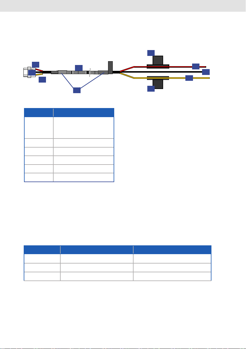
3.3 Power Connection
6
1
2
3
4
5
Position Description
1 Red
(see table "Power
Connection" for details)
2 Black
3 Yellow
4 Ribbed hose
5 Heat sink (2x)
6 Fuse 10 Amp
1
2
3
6
10
Power Connection
PIN No. Color Signal
1 Red Terminal 30 (Battery)
2 Black Terminal 31 (GND)
3 Yellow Terminal 15 (Ignition)
Page 11
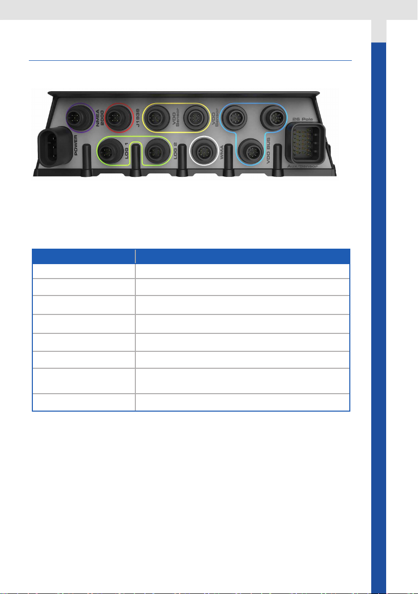
4. Connections
Nav Box: Connections
The NavBox features following
connection types:
Connections
Position
Description
POWER for 3 pin power cable
NMEA 2000
®
5 pin M12 Micro C
SAE J1939 1x SAE J1939 Input (5pin M12)
VDO Bus 3x VDO Bus (8 pin M12)
LOG 1 & LOG 2 2x Log Input (4 pin M12)
WMA 1x Wind Input (8 pin M12)
26 POLE AUX /
26 pin Analogue/NMEA0183 Input
SENSOR
VDO Sensor 2x CAN BusVDO Sensor Input (5 pin M12)
11
Page 12

NMEA 2000
4.1 NMEA 2000®
The Nav Box can be connected to an
existing NMEA 2000 system. Please
visit www.NMEA.org to nd information about NMEA 2000.
NMEA 2000 Pinout
PIN No. Signal
1 Shield
2 NET-S (V+)
3 NET-C (V−)
4 NET-H (CAN H)
5 NET-L (CAN L)
12
For NMEA 2000 voltage drop calculations
please refer to this LEN list:
Instrument LEN
Nav Box 3
Nav Control 4
110 mm Gauge 4
52 mm Gauge 2
4.3‘‘ TFT 12
Page 13

The Nav Box can receive and transmit
NMEA 2000 data. It can also convert
analogue, NMEA 0183 and SAE J1939.
It supports the reception of following
NMEA 2000 PGNs:
PGN HEX Message Name
59904 00EA00 ISO Request
60928 00EE00 ISO Address Claim
65281 00FF01 VDO Bus Proprietary Single-Frame Message
(End Of Line)
60416 00EC00 ISO Transport Protocol, Connection Manage-
ment - RTS group function
60160 00EB00 ISO Transport Protocol, Data Transfer
59392 00E800 ISO Acknowledgment
126208 01ED00 NMEA - Request group function
130306 01FD02 Wind Data
129026 01F802 COG & SOG, Rapid Update
128259 01F503 Speed, Water Referenced
128267 01F50B Water Depth
129025 01F801 Position, Rapid Update
129033 01F809 Local Time Offset
127250 01F112 Vessel Heading
127489 01F201 Engine Parameters, Dynamic
127488 01F200 Engine Parameters, Rapid Update
130312 01FD08 Temperature - DEPRECATED
130314 01FD0A Actual Pressure
127251 01F113 Rate of Turn
127257 01F119 Attitude
130310 01FD06 Environmental Parameters - DEPRECATED
130311 01FD07 Environmental Parameters- DEPRECATED
127245 01F10D Rudder
NMEA 2000
13
Page 14

SA E J19 39
PGN HEX Message Name
127505 01F211 Fluid Level
127493 01F205 Transmission Parameters, Dynamic
126992 01F010 System Time
130316 01FD0C Temperature, Extended Range
129283 01F903 Cross Track Error
129284 01F904 Navigation Data
127508 01F214 Battery Status
129291 01F90B Set & Drift, Rapid Update
For transmitting PGNs please refer to Chapter “SAE J1939” and Analogue Inputs.
In case multiple instances of the same
value are received from the NMEA
2000 network, the Nav Box has
following priorities:
• For Time Data:
1 - " System Time "
2 - "Local Time Offset"
• For Barometric Date:
1 - "ActualPressure"
2 - "EnvironmentalParameters2"
3 - "EnvironmentalParameters"
• For Temperature Data:
1 - "Temperature_Ext"
2 - "Temperature"
3 - "EnvironmentalParameters2"
4 - "EnvironmentalParameters"
4.2 SAE J1939
In general, if one message contains an
error value, the next one is considered.
NMEA 2000 Engine Support
The Nav Box system supports up to
four NMEA 2000 engines. The engines
have to be properly programmed with
individual instance numbers (0-3) by
an engine technician.
Please refer to the Operation manual
to set up the Tachometers with the
right instance numbers.
14
SAE J1939 Pinout
Page 15

PIN No. Signal
1 Shield (internally not connected)
2 Ignition (internally connected to battery when
system is ON)
3 GND
4 CAN H
5 CAN L
The Nav Box has three SAE J1939 connections:
SAE J1939 Installation
The Nav Box supports one SAE J1939
engine connection. .
SAEJ1939 Installation
Important:
If you use any of the three SAEJ1939
ports you need to terminate all three
SAE J1939 ports with three 180 ohm
resistors!
VDO offers an optional 180 ohm inline
terminator (A2C99794200).
Data Handling
The Nav Box has an interface that is
SAEJ1939 Multi Engine support
Four Engines in one CAN Bus system
SAE J1939 compatible. It is used to receive en gine data and distributes them
over VDO Bus and NMEA 2000 to make
them available for both the NMEA2000
network and the AcquaLink system.
The NavBox supports up to four SAE
J1939 engines if they are in the same
CAN Bus network system and have
different source addresses (0-3).
Supported SAE J1939 Messages:
SAE J1939 supported SPNs Description
PGN 61444 - SPN 190 Engine Speed
PGN 65270 - SPN 102 Engine Turbocharger Boost Pressure
PGN 65263 - SPN 100 Engine Oil Pressure
PGN 65262 - SPN 175 Engine Oil Temperature 1
PGN 65262 - SPN 110 Engine Coolant Temperature
PGN 65266 - SPN 183 Engine Fuel Rate
PGN 65253 - SPN 247 Engine Total Hours of Operation
PGN 65263 - SPN 109 Engine Coolant Pressure
15
Page 16

Data Handling
SAE J1939 supported SPNs Description
PGN 65276 - SPN 96 Fuel Level
PGN 65270 - SPN 173 Exhaust Gas Temperature
PGN 65269 - SPN 108 Barometric Pressure
PGN 65269 - SPN 171 Ambient Air Temperature
PGN 65272 - SPN 127 Transmission Oil Pressure
PGN 65272 - SPN 177 Transmission Oil Temperature
PGN 65279 - SPN 97 Water in Fuel Indicator
The Nav Box distributes the received
SAEJ1939 data to the NMEA 2000 network.
Following data is converted and
transmitted:
SAEJ1939 Input Data NMEA 2000 output
Engine Speed (RPM) 127488 Eng. Parameters, Rapid Update
Boost Pressure 127488 Eng. Parameters, Rapid Update
Engine Oil Pressure 127489 Eng. Parameters, Dynamic
Engine Oil Temperature 1 127489 Eng. Parameters, Dynamic
Engine Coolant Temperature 127489 Eng. Parameters, Dynamic
Engine Fuel Rate 127489 Eng. Parameters, Dynamic
Engine Total Hours of Operation 127489 Eng. Parameters, Dynamic
Engine Coolant Pressure 127489 Eng. Parameters, Dynamic
Fuel Level 127505 Fluid Level
Exhaust Gas Temperature 130316 Temperature Ext
Barometric Pressure 130314 Actual Pressure
Ambient Air Temperature 130316 Temperature Ext
Transmission Oil Pressure 127493 Trans. Parameter Dynamic
Transmission Oil Temperature 127493 Trans. Parameter Dynamic
16
The Nav Box also receives all
DM1 DTC messages of the SPN List
above.
Page 17

4.3 VDO Bus
VDO Bus Pinout
PIN No. Signal
1 Ignition / Terminal 15
2 GND / Terminal 31
3 Battery + / Terminal 30
4 CAN H
5 CAN L
6 Shield
7 Ignition / Terminal 15
8 GND / Terminal 31
VDO Bus
The VDO Bus is an NMEA2000-based
communication used within the Acqualink system to share the information
gathered from the system interfaces as
well as to distribute proprietary messages containing status information of the
system itself. The VDO Bus uses M12 8
Pin cables and all devices are powered
through the network.
The NavBox has three VDO Bus ports,
so three separate VDO Bus segments
can be installed. This helps to reduce
the power drop in the system and allows an easy installation in all areas of
the vessel.
Every 110mm gauge, 4.3’’ TFT
and Nav Control features two
equal VDO Bus connectors in the
rear.
The units are daisy chained together.
17
Page 18

VDO Bus
Important:
• All three VDO Bus segments have to
be terminated with a VDO Terminator
(included in box).
• If you haven’t connected an
instrument or Nav Control to
a Nav Box port, connect the
terminator directly to the not used
NavBox VDO port.
• If you have connected displays or
gauges, use the terminator on last
empty VDO port on the last unit in
the chain.
• There mustn't be any empty
connector
VDO Bus Limitations
Note:
VDO Bus cables have two female connectors. In order to extent the cable
length an optional gender changer
connector is needed (A2C38805500).
18
The NavBox provides power to all the
110mm gauges and 4.3’’ TFTs connected to the system. Due to the power
consumption and the resistance of the
cables, there are limitations of the maximum cable length and number of
possible instruments in the system.
In order to have a properly working
system the voltage drop of every of the
three VDO Bus segments have to be
calculated.
1 LEN = 0.05 Ampere
LEN List for VDO Products:
Instrument LEN
NavBox 3
NavControl 4
110 mm Gauge 4
52 mm Gauge 2
4.3‘‘ TFT 12
Page 19

Calculation
Calculation
12V power supply:
The voltage drop for every segment of
the VDO Bus is calculated as follow:
Ohm‘s Law: E (voltage drop) = I (circuit
current) x R (wire resistance)
R = 2/2x Cable Length (m) x Power
Pair Resistance / 100
I = LEN (Load Equivalency Number) x
0.050 amps
L = Total length of VDO Bus cables in
one segment
-> E = 0.05 x LEN x L x 0.057
The voltage drop for each VDO Bus
Segment shouldn’t be higher than 3V
4.4 VDO Sensor
You can connect the VDO Navsensor
and VDO NMEA 2000 Windsensor directly to the NavBox without using the
NMEA 2000 Network
Note:
VDO Bus has 2x AWG 22 Power/
Ground cables -> so there is different
voltage drop calculation than NMEA
2000.
24V power supply:
If using a 24V system the voltage drop
may not be higher than 9V.
Note:
The maximum Number of LEN in the
NavBox system is 120 equals 6 Ampere.
Note:
One 120ohm resistor has to be installed as close as possible to the sensor.
19
Page 20

NMEA 0183
4.5 NMEA 0183
The NavBox can receive NMEA 0183
data and distributes it over VDO Bus
and NMEA2000 to make them available for both the AcquaLink system and
the NMEA 2000 network.
The NavBox supports following NMEA
0183 sentences:
NMEA 0183 supported sentences Description
RMC Recommended Minimum Navigation
Information
MTW Sea-Water temperature
DBT Depth Below Transducer
VHW Water Speed and Heading
VTG Track Made Good and Ground Speed
XTE Cross-Track Error, Measured
MWV Wind Speed and Angle
HDM Heading - Magnetic
HDG Heading - Deviation & Variation
BWC Bearing and Distance to Waypoint, Latitu-
de, N/S, Longitude, E/W, UTC, Status
20
Page 21

The received data is converted to following NMEA 2000 data:
NMEA 0183
NMEA 0183
Input Data NMEA 2000 / VDO Bus output
sentence
UTC Time 126992 SystemTime
Latitude 129025 PosRapidUpdate
Longitude 129025 PosRapidUpdate
RMC
Speed Over Ground Not forwarded with this sentence
Only over VTG so far
MTW Water Temperature 130316 Temperature_Ext
DBT Depth, meters 128267 WaterDepth
True Heading –
VHW
Magnetic Heading 127250 VesselHeading
Speed Through Water 128259 Speed, Water Referenced
VTG Speed Over Ground 129026 COGSOGRapidUpdate
XTE Cross Track Error 129283Cross Track Error
MWV Wind Angle 130306 Wind
Wind Speed 130306 Wind
HDM Magnetic Heading 127250 VesselHeading
Magnetic Heading 127250 VesselHeading
HDG
Deviation 127250 VesselHeading
BWC Bearing (True) To Waypoint 129284 Navigation Data
21
Page 22

Analog Inputs
NMEA 0183 Connection
To connect a NMEA 0183 device to the
NavBox use the analogue harness included in the box.
Sensor NavBox Pin Color Description
NMEA 0183 Rx 20 White/Red NMEA 0183 Rx A
14 Brown/Red NMEA 0183 Rx B
4.6 Analogue Inputs
The NavBox allows supports several
analogue inputs. The received data is
displayed in the AcquaLink system
and converted to NMEA 2000 messages
26 Pole Aux/Sensor
22
26 Pole Pinout
26 Pole
1
20
14
8
2
21
15
9
3
22
16
10
4
23
17
11
5
24
18
12
6
25
19
13
7
26
Aux/Sensor
Page 23

Analogue Inputs
Position Description
1 Connector type: Tyco Super Seal 1.0 mm (Tyco PN: 1473416-1)
2 Shrink tube (2x)
3 Ribbed hose
6 Label imprint
Pin Signal In-/output range Coding TBD
1 Low Side Switch (Buzzer) 0.5A max brown
6 0-5V GND black
7 High Side (Aux) 0.7A max red
8 Engine Freq. GND - brown-blue
9 Engine Freq. (universal WWG) 0–4 kHz; W, 1, Ind,
white-blue
Generator, Lightning Coil
10 Engine Cool Water Temp 0–500 Ohm blue
11 NMEA0183 B (Talker) RS422 white
12 NMEA0183 A (Talker) RS422 white-grey
13 Engine Oil Temp 0–500 Ohm violet
14 NMEA0183 B (Listener) RS422 brown-red
15 Engine Oil Pressure 0–500 Ohm green
16 Rudder Angle 0–500 Ohm yellow
17 Fuel 1 0–500 Ohm white-green
18 Fuel 1 GND - brown-green
19 Transmission oil pressure 0–500 Ohm; 0–30 Bar pink
20 NMEA0183 A (Listener) - white-red
21 Fresh Water 4–20 mA white-yellow
22 Black Water 4–20 mA grey
23 Amperemeter (−) +/−60 mV yellow-brown
24 Amperemeter (+) +/−60 mV red-blue
25 Signal GND - pink-brown
26 0-5V (Signal 1) 0–5V grey-brown
23
Page 24

Fuel Level
4.6.1 Resistive Inputs
The NavBox implements six resistive
inputs to allow the connection of the
following sensors:
• Fuel Level sensor
• Rudder Angle sensor
• Engine Oil Temperature sensor
• Engine Oil Pressure sensor
• Transmission Oil Pressure sensor
• Engine Coolant Water Temperature
sensor
Fuel Level
There are three different Ohm ranges
for the fuel sensor input available:
• 2-90 ohm
• 3-18 0 o h m
• 240-33.5 ohm
24
Available VDO products:
A2C Number Description
226-801-015-001G Adjustable Lever Arm Sensor 10–180 ins grnd
A2C59510162 Adjustable Fuel Lever Arm Sensor 10–180 Ω w/c
A2C59510163 Adjustable Fuel Lever Arm Sensor 240–33 Ω w/c
A2C59510164 Adjustable Fuel Lever Arm Sensor 90–0 Ω w/c
A2C59510165 Adjustable Lever Arm Sensor ALAS I
A2C59510166 Adjustable Lever Arm Sensor ALAS I
A2C59510167 Adjustable Lever Arm Sensor ALAS I
A2C59510168 Adjustable Fuel Lever Arm Sensor 10–180 Ω wo/c
A2C59510169 Adjustable Fuel Lever Arm Sensor 240–33 Ω wo/c
A2C59510170 Adjustable Fuel Lever Arm Sensor 90–0 Ω wo/c
A2C59510171 Adjustable Lever Arm Sensor ALAS I
A2C59510172 Adjustable Lever Arm Sensor ALAS I
A2C59510173 Adjustable Lever Arm Sensor ALAS I
Page 25

Connection
Sensor NavBox Pin Color Description
Fuel 17 White/Green Fuel Input
GND 18 Brown/Green Fuel GND
For calibration please refer to the
Operation manual.
Rudder Angle
The NavBox system supports one resistive rudder sensor input.
Ohm range: 5–190 Ohm
A2C Number Description
A2C110295001 Rudder angle sensor single station 10–180 Ω
Rudder Angle
Connection
Sensor NavBox Pin Color Description
Rudder 16 Yellow Rudder Angle
GND 25 Pink/Brown Signal GND
For calibration please refer to the
Operation manual.
25
Page 26

Temperature Sensors
Temperature Sensors
The Nav Box supports one input for
engine oil and one for coolant oil temperature.
Available VDO sensors:
A2C Number Description
323-801-001-006N Temp Sender 120°C (Earth Ret) M14 x 1.5
323-801-001-007N Temp Sender 120°C (Earth Ret)
323-801-001-008N Temp Sender 120°C(Earth Ret)5/8-18UNF-3A
323-801-001-009N Temp Sender 120°C (Earth Ret)
323-801-001-010N Temp Sender 120°C (Earth Ret) 1/2-14NPTF
323-801-001-022N Temp Sender 120°C (Earth Ret)
323-801-001-029N Temp Sender 250F M16X1.5 801/1/29
323-801-001-040N Temp Sender 120°C (Earth Ret) M16 x 1.5
323-801-001-058C Temp Sender, Elec.
323-801-004-002N Temp Sender 150°C (Earth Ret) M14 x 1.5
323-801-004-003D Temp Sender 150°C (Earth Ret) R1/2
323-801-004-007D Temp Sender 150°C (Earth Ret) 1/2-14NPTF
323-801-004-012C Temp Sender 150°C (Earth Ret) M16 x 1.5
323-801-004-017D Temp Sender 150°C (Earth Ret)
323-801-004-039D Temp Sender 150°C (Earth Ret) M14 x 1.5
323-801-005-001D Temp Sender 250F 1/8-27NPT
323-801-008-002D Temp Sender Outside Air −25°+1
323-801-010-001D Temp Sender 150°C (Earth Ret) M10 X 1.5
323-801-012-001D Temp Sender 150°C (Earth Ret)
323-801-012-002D Temp Sender 150°C (Earth Ret)
323-801-012-003D Temp Sender 150°C (Earth Ret)
323-801-017-001N Temp Sender 120°C (Earth Ret) M10 X 1
26
Page 27

Temperature Sensors
A2C Number Description
323-805-001-001N TRAS.VDO 14*1,5 120° PI
323-805-001-002C Temp Sender 120°C(Insul/Ret)5/8
323-805-001-004N Temp Sender 120°C (Insul/Ret)
323-805-001-005N Temp Sender 120°C(Insul) 3/8-18 NPTF
323-805-001-015N Temp Sender 120°C (Insul/Ret) M18 x 1.5
323-805-003-001N Temp Sender 150°C (Insul/Ret) M14 x 1.5
323-805-003-002N Temp Sender 150°C (Insul) 1/4-18NPFT
323-805-003-003N Temp Sender 150°C (Insul/Ret) 5/8-18UNF
323-805-039-001C TRASM.130°C 14x1.5
323-805-042-001C Temp Sender 140°C (Insul) M14x1.5 Spec Con
A2C59515306 Temp Sender (Neutral Version A2C59900814)
A2C59515307 Temp Sender (Neutral Version A2C59900815)
A2C59900813 Temp Sender (PDMA2C53025662:323-805-55-1)
A2C59900816 Temp Sender (PDMA2C53308318:40250127)
323-803-001-001D Temp Sender 120°C( Earth) WC100° M14 x 1.5
323-803-001-004D Temp Sender 120°C (Earth) WC90° M14 x 1.5
323-803-001-006D Temp Sender 120°C (Earth) WC96°
323-803-001-007D Temp Sender 120°C (Earth) WC110°
323-803-001-008D Temp Sender 120°C (Earth) WC110° M14x 1.5
323-803-001-009D Temp Sender 120°C (Earth) WC102° M14x 1.5
323-803-001-011D Temp Sender 120°C (Earth) WC98° 5/8-18NF-3
323-803-001-012D Temp Sender 120°C (Earth) WC100° 5/8-18NF
323-803-001-013D Temp Sender 120°C (Earth) WC106° M14x 1.5
323-803-001-016D Temp Sender 120°C (Earth) WC94° M14x 1.5
323-803-001-019D Temp Sender 120°C (Earth) WC95° 1/2-14NPT
323-803-001-022D Temp Sender 120°C (Earth) WC118° M14x 1.5
323-803-001-025D Temp Sender 250F WC217F 1/2-14NPT
323-803-001-028D Temp Sender 120°C (Earth) WC98° M14x 1.5
27
Page 28

Pressure Sensors
A2C Number Description
323-803-001-030D Temp Sender 120°C (Earth) WC100° 1/2-14NPT
323-803-001-032D Temp Sender 250F WC230F 1/2-14NPT
323-803-001-059D Temp Sender 120°C (Earth) WC105° 5/8-18NF
323-803-001-060D Temp Sender 120°C (Earth) WC105° 1/2-14NPT
323-803-002-002D Temp Sender 150°C (Earth) WC120° M14X 1.5
323-803-002-007D Temp Sender 150°C (Earth) WC130° M14X 1.5
323-803-002-010C Temp Sender 150°C (Earth) WC135° M14x 1.5
323-803-002-016D Temp Sender 150°C (Earth) WC130° M14x 1.5
323-803-002-017D Temp Sender 150°C (Earth) WC120° M14x 1.5
323-803-002-019D Temp Sender 150°C (Earth) WC135° M14x 1.5
323-803-002-020D Temp Sender 150°C (Earth) WC110° M14x 1.5
325-805-003-001C Temp Sender 120°C (Insul) 1/4-18 D/Stat.
325-805-003-003C Temp Sender 120°C (Insul) 3/8-18
323-809-019-003A Temp Sender 120°C (Insul) M18x1.5 Spec Con
Connection
Sensor NavBox Pin Color Description
Temp 10 Blue Coolant Water Temp
GND 25 Pink/Brown Signal GND
For calibration please refer to the
Operation manual.
Pressure Sensors
The Nav Box supports one input for
engine oil and one for transmission oil
pressure.
Available VDO products:
28
13 Violet Engine Oil Temp
Page 29

TFT-Display einbauen
A2C Number Description
360-081-029-001C Press Sender 5 Bar (E/Ret) M10 x 1(Short)
360-081-029-001C Press Sender 5 Bar (E/Ret) M10 x 1(Short)
360-081-029-004C Press Sender 80 PSI 1/8-27NPT 29/4
360-081-029-008C Press Sender 5 Bar (E/Ret) 1/4-
360-081-029-012C Press Sender 150 PSI 1/8-27NPT 29/12
360-081-029-013C Press Sender 10 Bar (E/Ret) M12x1.5
360-081-029-020C Press Sender 10 Bar (E/Ret) 1/4-18NPTF
360-081-029-026C Press Sender 5 Bar (E/Ret) M14
360-081-029-026K Press Sender 5 Bar (E/Ret) M14 x 1.5
360-081-029-033C Press Sender 10 Bar (E/Ret) M14 x 1.5
360-081-029-041C Press Sender 5 Bar (E/Ret) 1/8-27NPTF
360-081-029-042C Press Sender 10 Bar (E/Ret) 1/8-27NPTF
360-081-029-059C Press Sender 5 Bar (E/Ret) M18 x 1.5
360-081-029-062C Press Sender 10 Bar 1/8-28BSP 2
360-081-029-085C Press Sender 5 Bar (E/Ret) M12
360-081-037-003C Press Sender 25 Bar (E/Ret) M18 x 1.5
360-081-037-006C Press Sender 16 Bar (E/Ret) M14 x 1.5
360-081-037-007C Press Sender 16 Bar (E/Ret) 1/8-27NPTF
360-081-037-008C Press Sender 25 Bar (E/Ret) M10 x 1
360-081-037-010C Press Sender 25 Bar (E/Ret) 1/8-27NPFT
360-081-037-017C Press Sender 25 Bar (E/Ret) M14 x 1.5
360-081-037-018C Press Sender 25 Bar (E/Ret) M18 x 1.5
360-081-037-019C Press Sender 16 Bar (E/Ret) M12 x 1.5
360-081-032-001C Press Sender 5 Bar (Insul/Ret) 1/8-27NPFT
360-081-032-002C Press Sender 5Bar (Insul/Ret) M10x1
360-081-032-003C Press Sender 10 Bar (Insul/Ret) M10x1
360-081-032-004C Press Sender 10 Bar (E/Ret) M12 x 1.5
360-081-032-006C Press Sender 10 Bar (Insul/Ret) M14 x 1.5
360-081-032-007C Press Sender 5 Bar (Insul/Ret) 1/8-27NPTF
360-081-032-011C Press Sender 2 Bar (Insul/Ret) M12 x 1.5
360-081-032-013C Press Sender 5 Bar (Insul/Ret) M18 x 1.5
Pressure Sensors
29
Page 30

Pressure Sensors
A2C Number Description
360-081-032-014C Press Sender 150 PSI FG 1/8-27NPT 32/14
360-081-032-025C Press Sender 2 Bar (Insul/Ret)1
360-081-032-053C Press Sender 10 Bar (Insul/Ret) M12 x 1.5
360-081-032-057C Press Sender, Elec.
360-081-032-058C Press Sender, Elec.
360-081-032-060C Press Sender 5 Bar (Insul/Ret) M14 x 1.5
360-081-038-001C Press Sender 25 Bar (Insul/Ret)
360-081-038-002C Press Sender 25 Bar (Insul/Ret)
360-081-038-003C Press Sender 25 Bar (Insul/Ret)1/8-27nptf
360-081-038-005C Press Sender 25 Bar (Insul/Ret) M18 x 1.5
360-081-051-012C Press Sender 10 Bar (Insul/Ret) M16 x 1.5
360-081-051-013C Press Sender 7 Bar (Insul/Ret)1/8-27NPTF
360-081-030-004C Press Sender 5 Bar (E/Ret) W/C
360-081-030-008C Press Sender 5 Bar (E/Ret) W/C 0.5 M12
360-081-030-009C Press Sender 150 PSI WC7 M10X1K 30/9
360-081-030-010C Press Sender 5 Bar (E/Ret) W/C1.4 1/8-27
360-081-030-015C Press Sender 10 BAR WC0.8 1/8-27NPT
360-081-030-017C Press Sender 10 Bar (E/Ret) W/C0.9 M10x1
360-081-030-018C Press Sender 5 Bar (E/Ret) W/C1.2 M10x1
360-081-030-019C Press Sender 10 Bar (E/Ret) W/C1.5 M12
360-081-030-020C Press Sender 80 PSI(E/Ret) W/C8
360-081-030-022C Press Sender 10 Bar (E/Ret) W/C
360-081-030-023C Press Sender 80 PSI WC7 1/8-27NPT 30/23
360-081-030-028C Press Sender 5 Bar(E/Ret)W/C0.5
360-081-030-030C Press Sender 10 Bar(E/Ret)W/C0.7 M14x1.5
360-081-030-032C Press Sender 10 Bar(E/Ret)W/C0.5 M14x1.5
360-081-030-036C Press Sender 5 Bar(E/Ret)W/C0.5 M18x1.5
360-081-030-037C Press Sender 10 Bar(E/Ret)W/C0.75 M18x1.5
360-081-030-039C Press Sender 10 Bar(E/Ret)W/C0.75 M10x1
360-081-030-041C Press Sender 10 Bar(E/Ret)W/C2.
360-081-030-049K Press Sender 5 Bar(E/Ret)W/C0.4 1/8-27NPT
360-081-030-052C Press Sender 10 Bar(E/Ret)W/C0.4 1/8-27NP
30
Page 31

Pressure Sensors
A2C Number Description
360-081-030-063C Press Sender 10 Bar (E/Ret) W/C1.0 M14x1.5
360-081-030-070C Press Sender 10 Bar (E/Ret) W/C0.5 M18x1.5
360-081-030-071C Press Sender 5 Bar (E/Ret) W/C0.4 M14x1.5
360-081-030-074C Press Sender 10 Bar (E/Ret) W/C0.5 M18x1.5
360-081-030-086C Press Sender 5 Bar (E/Ret) W/C0.5 1/8-27NPT
360-081-030-097C Press Sender 5 Bar (E/Ret) W/C0.5 M14x1.5
360-081-030-100C Press Sender 10 Bar (E/Ret) WC4.0 1/8-27NPT
360-081-030-107C Press Sender 10 Bar (E/Ret) W/C5.
360-081-030-112C Press Sender 10 Bar(E/Ret)W/C1.35 M10x1
360-081-030-119C Press Sender 5 Bar(E/Ret)WC1.4 1/8-27NPTF
360-081-030-122C Press Sender 10 Bar (E/Ret) W/C0.75 M18x1.5
360-081-030-138C Press Sender 10 Bar (E/RET) W/C1.25 1/8-27
360-081-030-152C Press Sender 10 Bar (E/Ret) W/C5.2 M10x1
360-081-030-157C Press Sender 5 Bar (E/Ret) W/C0.5 M18x1.5
360-081-034-002C Press Sender 5 Bar (E/Ret) W/C0.25 M14x1.5
360-081-053-003C Press Sender 25 Bar (E/Ret) W/C5.5 M18x1.5
360-081-061-002C Press Sender 10 Bar (E/Ret) W/C0.7 M14x1.5
360-081-061-006C Press Sender 10 Bar (E/Ret) W/C5.0 M12x1.5
360-081-062-002A Press Sender 5 Bar (E/Ret) W/C0.4 M14x1.5
360-081-062-003C Press Sender 10 Bar (E/Ret) W/C5.5 M14x1.5
360-081-062-004A Press Sender 5 Bar (E/Ret) W/C1.0 M14x1.5
360-081-062-005A Press Sender 10 Bar (E/Ret) W/C3.0 M14x1.5
360-081-039-002C Press Sender 5 Bar (Insul) WC0.8 1/8-27NPTF
360-081-039-003C Press Sender 10 Bar (Insul) WC0.8 1/8-27NPT
360-081-039-004C Press Sender 80 PSI (Insul) WC10 1/8-27NPTF
360-081-039-007C Press Sender 10 Bar (Insul) WC1.0 M14 x 1.5
360-081-039-015C Press Sender 5 Bar (Insul) WC0.25 1/8-27
360-081-063-001C Press Sender 10 Bar (Insul) WC5.2 M12 x 1.5
360-081-064-001C Press Sender 5Bar (Insul) WC0.25 M18 x 1.5
360-081-064-003C Press Sender 5 Bar (E/Ret) W/C0.25 M18x1.6
360-081-064-004C Press Sender 10 Bar (Insul) WC0.6 M18 x 1.5
362-081-001-002C Press Sender 150 PSI 1/8-27NPT
31
Page 32

Resistive Data Conversion
A2C Number Description
360-081-030-085C Press Sender, Elec.
362-081-001-002K Press Sender, Elec., DUAL-STATIO
362-081-002-001K Press Sender 350 PSI 1/8-27NPT
362-081-002-003C Press Sender 400 PSI (E/Ret) 1/
362-081-002-004C Press Sender 400 PSI (E/Ret) 1/
362-081-003-002K Press Sender 150 PSI 1/8-27NPT DUAL
362-081-004-001C Press Sender 350 PSI DUAL 4:1
365-100-010-121C Electronic Press Sensor 10 bar (40692031)
365-100-016-121C Electronic Press Sensor 16 bar (40692032)
365-100-030-121C Electronic Press Sensor 30 bar (40692033)
Connection
Sensor NavBox Pin Color Description
Pressure 15 Green Engine Oil Pressure
19 Pink Transmission Oil Pressure
GND 25 Pink/Brown Signal GND
32
For calibration please refer to the
Operation manual.
4.6.2 Resistive Data Conversion
The received data is converted to
NMEA 2000 data and transmitted to a
NMEA 2000 network
Resistive Input Data NMEA 2000 / VDO Bus output
Fuel Level 127505 Fluid Level
Rudder Angle 127245 Rudder
Engine Oil Temperature 127489 Eng. Parameters,
Engine Oil Pressure 127489 Eng. Parameters,
Transmission Oil Pressure 127493 Trans. Parameter Dynamic
Coolant Water Temperature 127489 Eng Parameters
Page 33

Resistive Data Conversion
Current Inputs (4 ... 20 mA)
The NavBox implements two 4 ... 20 mA
current inputs to allow the connection
of the following sensors:
• Fresh Water sensor
• Waste Water sensor
Available VDO products:
A2C Number Description
N02-240-802 OL Watertanksensor 600 mm
N02-240-902 Sender Black Water 600 mm 4–20 mA 12/24 V
N02-240-904 Sender Black Water 1200 mm 4–20 mA 12/24 V
N02-240-906 Sender Black Water 1500 mm 4–20 mA 12/24 V
N02-240-402 Sensor Fresh water 600 mm 4–20 mA 12/24 V
N02-240-404 Sensor Fresh water 1200 mm4–20 mA12/24 V
N02-240-406 Sender Fresh Water 1500 mm 4–20 mA 12/24 V
Connection
Sensor NavBox Pin Color Description
4..20mA 21 White/Yellow Fresh Water
22 Grey Waste Water
GND 25 Pink/Brown Signal GND
For calibration please refer to the
Operation manual.
Data Conversion
The received data is converted to
NMEA 2000 data and transmitted to a
NMEA 2000 network
Current Input Data NMEA 2000 / VDO Bus output
Fresh Water Level 127505 Fluid Level
Waste Water Level 127505 Fluid Level
33
Page 34

Frequency Input
4.6.3 Frequency Input
The NavBox supports one frequency
input to allow the connection of the
following sensors:
• Engine Speed signal (pulses)
The frequency range for this input
is 0 to 4kHz.
Supported VDO products:
A2C Number Description
340-216-005-001C Generator Sender 90 mm Alt. 2159-50004201
340-216-005-002C Generator Sender 63 mm Alt. 2159-50004401
340-216-010-003C Generator Sender 25 mm Alt. 2159-50004601
A2C59513983 Blocking Oscilator
340-216-010-004C Generator Sender 90.2 mm M18x1.5 21.5-30V
340-804-005-001C Inductive Sender 35 mm (Kostal)
340-804-005-007C Inductive Sender 35 mm (Kostal)
340-804-005-013A Inductive Sender 71.4 mm (Kostal) M18x1.5
340-804-005-028C Inductive Sender 63.4 mm (Kostal) M18x1.5
340-804-005-033C Transm. Inductive 18x1.5 L.T.63
340-804-006-002C Inductive Sender Unit, Elec.
340-804-006-007C Inductive Sender 34 mm (Blade) M18x1.5
340-804-007-002A Inductive Sender 28.5 mm (Blade) M18x1.5
340-804-007-003C Inductive Sender 34 mm (Blade) M18x1.5
340-804-007-004C Inductive Sender 28.5 mm (Blade)3/4-16UNF
340-804-007-011C Inductive Sender 34 mm (Blade) M18x1.5
340-804-007-011G Inductive Sender 34 mm (Blade) M18x1.5
340-804-007-019C Inductive Sender 70.7 mm (Blade) M18x1.5
340-804-030-005B Inductive Sender 25 mm M18x1.5
340-804-077-007C Sensor Turbo Speed DDC
340-807-001-001C Generator Type Sender 3000 RPM
340-807-001-003C Generator Type Sender 3000 RPM
34
Page 35

A2C Number Description
340-808-001-001C Generator Type Sender 3000 RPM
340-808-001-002C Generator Type Sender 3000 RPM
Connection
Sensor NavBox Pin Color Description
Freq. 9 White/Blue Engine Freq.
GND 8 Brown/Blue Engine Freq. GND
For calibration please refer to the
Operation manual.
Data Conversion
The received data is converted to
NMEA 2000 data and transmitted to a
NMEA 2000 network.
Ampere Input
Current Input Data NMEA 2000 / VDO BUS output
Engine Speed (RPM) 127488 Eng. Parameters, Rapid Update
4.6.4 Ampere Input
The NavBox supports one ampere
input.
The voltage range for this input shall
be 0 to +/−60mV.
Supported VDO products:
A2C Number Description
A2C59514043 SHUNT AMMETER 60A
A2C59514047 SHUNT AMMETER 150A
35
Page 36

Buzzer Output
Connection
Sensor NavBox Pin Color Description
Ampere 23 Yellow/Brown Amperemeter (−)
24 Red/Blue Amperemeter (+)
For calibration please refer to the
Operation manual.
Data Conversion
The received data is converted to
NMEA 2000 data and transmitted to a
NMEA 2000 network.
Current Input Data NMEA 2000 / VDO BUS output
Battery Current 127508 - Battery Status
36
4.7 Buzzer Output
The NavBox buzzer output can be ac-
tivated in alarm situations and congu-
red through the alarm menu.
Connection
Sensor NavBox Pin Color Description
Buzzer (LSS) 1 Brown Buzzer Out (Low Side Switch)
GND 25 Pink/Brown Signal GND
4.8 USB
In the current software version the
USB connection can only be used for
service functions.
Page 37

4.9 Log Port
Log Port Pinout
PIN No. Signal In-/output range
1 Sensor Power 8V
2 LOG IN 0.2–800Hz
3 GND 0.2–800Hz
Log Port
The NavBox supports two VDO Sumlog sensors. The system automatically
detects the sensor with the faster
speed through water data and distributes it to the system.
All VDO Sumlog sensors are compatible.
Please refer to the Sumlog installation
instruction for details.
Data Conversion
PGN Description
128259 Speed, Water Referenced
37
Page 38

WMA Port
4.10 WMA Port
WMA Port Pinout
PIN No. Signal In-/output range
1 Power 8V
2 Not Used
3 COS 2-6V
4 GND 0V
5 SIN 2–6V
6 Wind Speed 0.8–100Hz
7 Not Used
8 Not Used
The NavBox supports one analogue VDO Windsensor
38
Following sensors are supported:
• “Standard” Series Sensors
• Logic Series Sensors
• AcquaLink analogue Sensors
Please refer to the Windsensor installation instruction for details.
Data Conversion
PGN Description
130306 Wind Data
Page 39

5. Hardware Specifications
Hardware Specifications
39
Page 40

Hardware Specifications
40
Position
Description
Housing Material Al Mg9 F/ e-coated (epoxy based) black RAL9005
Top Cover PBT GB20 black
Connectors VDO Bus: 3x M12 8 Pin; Power: 3 Pin AMP Superseal;
NMEA 2000: 1x M12 5 Pin; SAEJ1939: 1x M12 5 Pin;
WMA: 1x M12 8 Pin, Log: 2x M12 4 Pin; 26 Pin Analogue Harness
Operating temperature −20° / +70°
Storage temperature −40 / +85°
Operating voltage range 8 – 28 VDC
Protection Class IP 67
According to IEC 60529:2001; in nominal position
EMC DIN-EN 61000-6-2:2006 IEC 60945:2002
Approval CE
Page 41

41
Page 42

Continental Automotive Switzerland AG
Industriestrasse 18
9464 Rüthi
Switzerland
Phone: +41 7176 79-111
www.marine.vdo.com/
VDO – A Trademark of the Continental Corporation
The info rmati on provi ded in this broc hure co ntains o nly gene ral des cript ions or p erfo rmanc e characteristic s,
which do not always apply as descri bed in ca se of actual use or w hich may c hange as a result of f urther devel opment of the produc ts. Thi s infor mation i s merel y a techni cal des cript ion of th e product. It is not meant or i ntende d
to be a special guarantee for a particular quality or particular durability. An obligation to provide the respective
charac teristics sh all only ex ist if exp ressly agreed i n the ter ms of contract. We reser ve the right to make c hanges
in availab ility a s well as te chnic al chan ges wit hout pr ior noti ce.
A2C12119500 | C ontine ntal Automotive Switzerlan d AG I Englis h © 2016
42
 Loading...