

Page 1
SingleViu
TM
User Manual
for SingleViu gauges
Please keep this manual for future reference.
Read manual before attending any work.
www.continental-singleviu.com
EN
Page 2
User Manual
EN
SingleViu
Dear customer,
Congratulation on purchasing a gauge of the SingleViu family.
This user manual applies to SingleViu, a family of single gauges of the Continental company. It addresses technicians and
users and contains relevant information that may be necessary for correct usage of the gauge.
Please keep this manual carefully for future reference.
This operating manual contains important instructions for safe and correct assembly and usage of
the SingleViu gauges. Carefully read all relevant chapters before you start any work with the gauge.
Pictures and illustrations within this user manual show examples of gauges. The gauge at hand may
vary, e.g. in diameter or dial design.
For further information and additional technical documentation for this product please contact your local VDO-Partner. Also
visit us on our web page.
Sincerely, Continental
Continental Automotive GmbH
Sodener Strasse 9
65824 Schwalbach
Germany
singleviu@continental-corporation.com
www.continental-singleviu.com
TM
2 - 40
VDO – A trademark of the Continental Corporation
The reproduction, distribution and utilization of this document as well as the communication of its contents to others without
express authorization is prohibited. Offenders will be held liable for the payment of damages. All right reserved in the event
of the grant of a patent, utility model or design.
We reserve the right to make changes in availability as well as technical changes without prior notice.
TU00-0761-5207102
Version: 2.2 • 2018.01
Technische Änderungen vorbehalten – Technical details subject to change
Page 3

User Manual
EN
SingleViu
TM
Table of contents
1. General 4
1.1 Symbols in this manual 4
1.2 Definitions and Abbreviations 4
1.3 Homologation 5
2. Safety instructions 6
2.1 ... regarding users 6
2.2 ... regarding intended use 6
2.3 ... before installation 6
2.4 ... regarding mounting position 6
2.5 ... during electrical installation 7
2.6 ... after installation 7
3. Technical data 8
3.1 Dimensions 8
3.2 Environmental and electrical durability 8
3.3 Electrical connection 8
3.4 Pin description 9
4. Composition and Functions 12
4.1 Pointer 13
4.2 Tell-tales 13
4.3 Display and push-button 14
4.4 Illumination 14
4.5 Send indication value onto CAN 14
4.6 External Buzzer 14
5. Variants overview 15
5.1 Variants 52 mm 15
5.2 Variants 80 mm 20
5.3 Variants 100 mm 20
5.4 Package content 20
6. Handling and Mounting instruction 21
6.1 Transportation and storage 21
6.2 Disconnect the power supply 21
6.3 Prepare the mounting space 21
6.4 Mounting of the connector 22
6.5 Mounting the gauge 24
6.6 Reconnect the power supply 24
7. Configuration and initial setup 25
7.1 Configuration via SingleViu ConfigTool 25
7.2 Configuration via push-button 29
8. Operating menu 31
8.1 Operating menu for gauge with diameter 52 mm 31
8.2 Operating menu for speedometers 31
8.3 Operating menu for tachometers 32
9. Replacement of gauges of predecessor series 33
9.1 Replacement of Viewline 33
9.2 Replacement of World Wide Gauges 34
9.3 Replacement of CANcockpit 36
10. Maintenance 37
11. Shutdown and Disposal 37
11.1 Disconnect the power supply 37
TU00-0761-5207102
11.2 Dismantling 37
11.3 Reconnect the power supply 38
11.4 Decommissioning and disposal 38
12. Accessories and spare parts 39
12.1 Spare parts 39
12.2 Adapter cables, connector and crimp contacts 39
12.3 SingleViu ConfigTool, Programming dongle and CAN Boxen 39
3 - 40
Version: 2.2 • 2018.01
Technische Änderungen vorbehalten – Technical details subject to change
Page 4
User Manual
EN
SingleViu
TM
1. General
1.1 Symbols in this manual
Read the relevant parts of the manual completely and carefully before attending the work on the gauge.
Nonobservance of the safety instructions may lead to injuries or damages.
For questions or obscurities approach to your ►VDO-Partner.
Symbols in this manual are used as follows:
» Instructions are marked with this double arrow.
► An arrow marks a keyword, that is defined in a separate chapter. You can find the full list of all keywords in the glos-
sary, chapter definitions 1.2.
This symbol warns of dangers for your health and possible injuries.
This symbol indicates possible damages of the product or other property.
REMARK:
Additional information on the product or current action.
4 - 40
1.2 Definitions and Abbreviations
Accessories Usable articles except gauge and mounting nut. (chapter 12)
CAN bus SAE J1939 Vehicle bus system with network protocol SAE J1939.
ConfigTool Receive SingleViu ConfigTool via ►VDO-Partner. (chapter 7.1)
Configuration,
Configuration menu
Connector Connector of cable harness to SingleViu gauge. (chapter 12.2 and chapter 6.3)
Contact cable Pre-assembled cable to connect a gauge. (chapter 12.2)
Declaration of conformity
Dongle
Homologation UN-ECE R10 (chapter 1.3.2). Receive the certificate via ►VDO-Partner.
IMDS
Operationmenu Menu that contains different information in driving mode. (chapter 8)
Push-button Internal or external push-button. (chapter 4.3)
RGB Color space with the three primary colors red, green and blue.
Sensor curve Preset and adjustable sensor curve for analog sensor data. (chapter 5.1)
Tell-tales Integrated tell-tales in the gauge. (chapter 4.2)
U
Bat
U
TU00-0761-5207102
DC
Variants overview List of all SingleViu variants. (chapter 5)
VDO-Partner
Warning thresholds Thresholds to activate tell-tale 1 (chapter 4.2)
The gauges can be configurated via ConfigTool (chapter 7.1) or via Push-button in
the configuration menu. (chapter 7.2)
CE mark for conformity with EU regulations (chapter 1.3.1).
Receive the certificate via ►VDO-Partner.
USB-stick containing license to change locked parameters.
(chapter 7.1 and chapter 12.3)
International material database of automotive industry that contains all parts of
SingleViu gauges. Excerpt available via ►VDO-Partner.
Battery voltage and actual supply voltage UDC.
Direct current voltage.
Partner company of Continental and regional distributor of SingleViu.
A list of VDO-Partners is available in the partner finder: www.vdo-partner.com
Version: 2.2 • 2018.01
Technische Änderungen vorbehalten – Technical details subject to change
Page 5
User Manual
EN
SingleViu
TM
1.3 Homologation
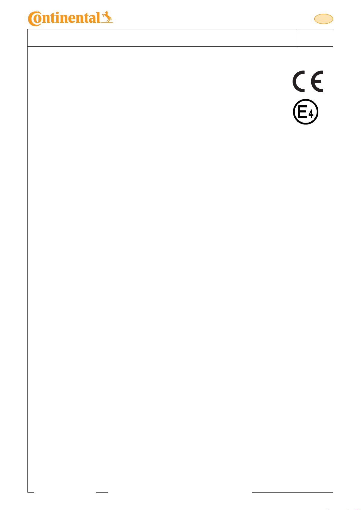
1.3.1 CE mark
All gauges of the SingleViu family have been developed and produced in compliance
to EU regulation 765/2008 and therefore show the “CE” mark on their label.
The official ►declaration of conformity is available.
1.3.2 Homologation according to UN-ECE
The gauge of the SingleViu family have been tested according to regulation UN-ECE
10R („electromagnetic compatibility“) and the type has been homologated.
The gauges therefore show the “E” mark on their label.
The official ►Homologation is available.
5 - 40
TU00-0761-5207102
Version: 2.2 • 2018.01
Technische Änderungen vorbehalten – Technical details subject to change
Page 6

User Manual
EN
SingleViu
TM
6 - 40
2. Safety instructions
2.1 ... regarding users
• This manual addresses technicians and users.
• Technicians are appropriately trained or experienced persons with basic knowledge of the vehicle / shipbuilding electrical system and mechanics. Installation, configuration and commissioning of the product must be carried out by a technician to prevent personal injury, property damage or environmental damage.
• Users are in particular drivers and other personnel of the target vehicle who operate and clean the gauges. Users must
be instructed in the function of the gauge before use.
2.2 ... regarding intended use
• The gauge is designed for use in ground vehicles and machines as well as in pleasure boats, either for commercial or
private use.
• The gauge is designed for nominal voltages of 12 or 24 V
damaged.
• The gauge may only be used to display specific vehicle or machine parameters.
• Changes or manipulations may have an impact on safety. Changed, manipulated or damaged gauges must not be
used.
2.3 ... before installation
• Wear appropriate work clothing. Do not wear loose clothing, as it may get caught in moving parts. Protect long hair with
a hair net.
• Ensure appropriate surrounding conditions. Before working underneath the vehicle, secure it thoroughly.
• Make sure that the engine cannot start unintentionally during installation.
• When removing/installing seats, covers, etc., ensure that lines are not damaged and plug-in connections are not loosened.
• Note all data from other installed gauges with volatile electronic memories.
. If the nominal voltage is exceeded, the gauge may be
DC
2.4 ... regarding mounting position
• Consider the needed clearance behind the gauge and its mounting hole diameter.
• The gauge must not impair the driver’s field of vision.
• Do not install the gauge in the mechanical and electrical airbag area.
• Do not drill holes or ports in load-bearing or stabilizing stays or tie bars.
• If installing the gauge near a magnetic compass, note the magnetic safe distance to the compass. Recommendation:
Minimum 30 cm.
• Pay attention to how lines and cable harnesses are laid so that you do not damage them.
• Drill small ports; enlarge and complete them, if necessary, using taper milling tools, saber saws, keyhole saws or files.
Deburr edges.
TU00-0761-5207102
Version: 2.2 • 2018.01
Technische Änderungen vorbehalten – Technical details subject to change
Page 7

User Manual
EN
SingleViu
TM
7 - 40
2.5 ... during electrical installation
• Before beginning, remove voltage supplies. Disconnect the negative terminal on the battery and auxiliary batteries.
• Faulty connections can cause short circuits. Only connect cable according to specified pin assignment.
• Only use fused voltage supply. Recommendation: 5 Amp fuse.
• Use cables with sufficient cross-sectional area and insulation. Reducing the cable cross-sectional area leads to higher
current density which can cause the cable cross-sectional area in question to heat up.
• When installing electrical cables, use the existant cable ducts and harnesses; however, do not run cables parallel to
ignition cables or to cables that lead to large electricity consumers.
• Fasten cables with cable ties or adhesive tape. Do not run cables over moving parts. Do not attach cables to the steering column. Ensure that cables are not subject to tensile forces.
• If cables are run through drill holes, protect them using rubber sleeves or the like.
• Use only a cable stripper to strip the cable and adjust it so that stranded wires are not damaged or separated.
• Use only a soft soldering process or commercially available crimp connector to create new cable connections.
• Make crimp connections with cable crimping pliers only.
• Insulate exposed stranded wires to prevent short circuits.
2.6 ... after installation
• Do not operate vehicle/machine with faulty connections or damaged cables.
• Reconnect the ground cable tightly to the negative terminal of the battery and auxiliary batteries.
• Reenter/reprogram the volatile electronic memory values.
• Check all functions of vehicle/machine.
TU00-0761-5207102
Version: 2.2 • 2018.01
Technische Änderungen vorbehalten – Technical details subject to change
Page 8
User Manual
EN
SingleViu
TM
3. Technical data
3.1 Dimensions
Mounting hole diameter 52 - 53 mm 80 - 81 or 85 - 86 mm 100 - 101 mm
Device diameter 52 mm 80 mm 100 mm
Device depth 76 mm 80 mm 80 mm
Mounting depth incl. connector 110 mm 110 mm 110 mm
Weight 78 g 100 g 120 g
3.2 Environmental and electrical durability
Operating temperature range
Storage temperature range -40 °C to +85 °C (-40 °F to +185 °F)
Level of protection IP 67 (without connector IP 40)
Chemical durability
Mechanical shocks
Vibration
Temperature shock
Climatic storage
Salt spray test 5% NaCl, 672 h
EMC
Inverse-polarity protection yes
-40 °C to +80 °C (-40 °F to +176 °F)
Display: -20 °C to +80 °C (-4 °F to +176 °F)
- ammonia based cleaner
- methylated spirits
- interior cleaner
- drinks containing caffeine and tannin (coffee, tea and cola)
Continuous
Single
Free fall
Periodic
Stochastic
Range
Transformation time
Retention time
Range
Rel. humidity
Radiated Emission
Immunity
Bulk current injection
25 g; 6 ms
100 g; 11 ms
1 m
2 g; 8 - 500 Hz
4.2 g; 10 - 1000 Hz
-40 °C to +85 °C
10 seconds
2 h
+25 °C to +55 °C
80% to 100%
CISPR25 class 3
IEC 61000-6-2 class A
ISO11452-4 class A
8 - 40
3.3 Electrical connection
Nominal voltage 12 VDC or 24 V
Operation voltage range 8 VDC to 32.5 V
Current consumption < 200 mA at nominal voltage
Quiescent current < 3 mA
TU00-0761-5207102
DC
DC
Version: 2.2 • 2018.01
Technische Änderungen vorbehalten – Technical details subject to change
Page 9
User Manual
EN
SingleViu
TM
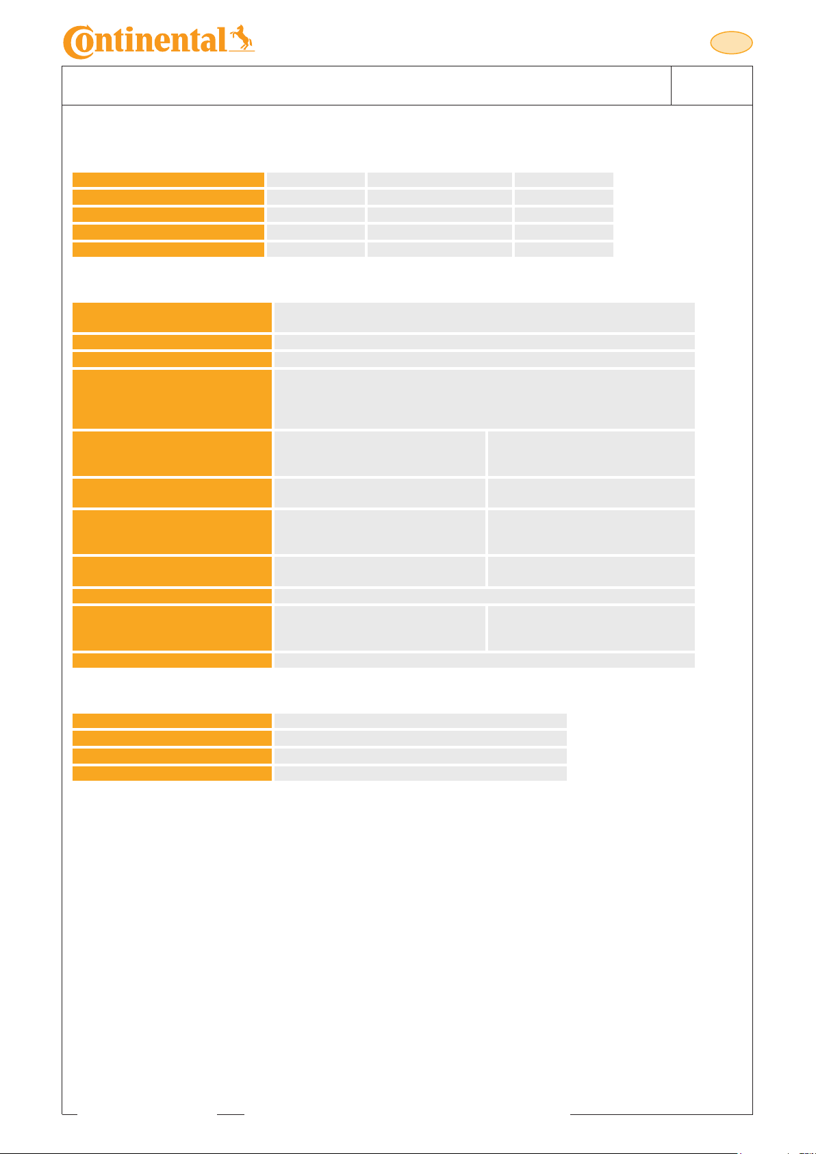
3.4 Pin description
3.4.1 8-pin connector
Every SingleViu gauge contains a contact for a ►connector MOLEX 334724801 with 8 pins.
Pin Description Remark Cable color ►contact cable
1 Terminal 30 Battery Plus (12/24 V
2 Terminal 31 Battery Minus (Ground) black
3 Sensor ground Ground reference for sensor signal blue
4 Terminal 15 Ignition brown
5 Sensor input Contact for analog sensor signal green
6 Terminal 58 Illumination blue/red
7 CAN High Input for CAN bus SAE J1939 white
8 CAN Low Input for CAN bus SAE J1939 pink
) red
DC
30
31
15
9 - 40
58
brown
black
red
Sensor
ground
1
4
5
Fig. 3.1: Molex 8-pin connector
Pin 1: Power Supply (Terminal 30)
U
= +8 VDC to +32.5 V
Bat
The gauge is supplied with permanent power through this terminal. Current consumption is less than 200 mA in operation
mode at 12 V
0.5 V.
Pin 2: Ground (Terminal 31)
Ground connection for the gauge’s power supply.
8
DC
and less than 3 mA quiescent current. After an over- or undervoltage event, restart will be debounced by
DC
Sensor
input
CAN High
CAN Low
Fig. 3.2: Wiring diagram 8-pin connector
blue
84
1
5
blue/red
white
green
pink
Pin 3: Sensor ground
Ground reference for the analog sensor input, see pin 5.
Pin 4: Ignition (Terminal 15)
Range: 0 V to U
TU00-0761-5207102
Wake over CAN is also possible.
Version: 2.2 • 2018.01
Switch on at >4 VDC, switch off at <2.5 VDC, debouncing time of 200 ms.
Bat.
Technische Änderungen vorbehalten – Technical details subject to change
Page 10
User Manual
EN
SingleViu
Pin 5: Sensor input
Sensor input depends on gauge variant with its analog input.
a) Resistive input
Range: 0 to 500 Ohm
b) Voltage input
Range: 0 to 6 V or -100 to +100 mV
c) Frequency input
U
The predefined ►sensor curve depends on gauge variant.
Pin 6: Illumination (Terminal 58)
Range: 0 V to U
Pin 7: CAN High
Contact pin for CAN High according to ISO 11898 without termination resistance. SingleViu is capable for use with
►CAN bus SAE J1939.
Pin 8: CAN Low
Contact pin for CAN Low according to ISO 11898 without termination resistance. SingleViu is capable for use with
►CAN bus SAE J1939.
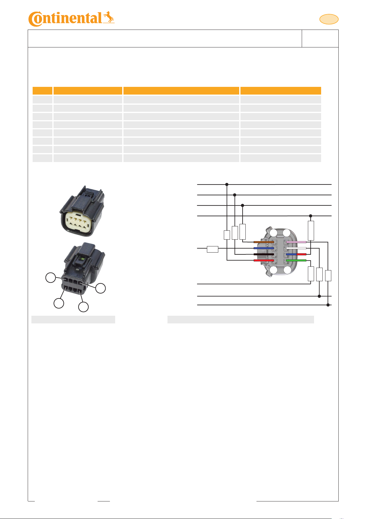
3.4.2 12-pin connector
SingleViu gauges with diameter of 80 and 100 mm contain an additional contact for a ►connector
MOLEX 334721201 with 12 pins.
low
TM
< 0.2 V, U
Switch on at >4 VDC, switch off at <2.5 VDC, debouncing time of 200 ms.
Bat.
> = 1 V. Frequencies up to 400 kHz are possible.
high
10 - 40
Pin Description Remark Cable color ►contact cable
1 CAN High Opt. input for CAN bus SAE J1939 white
2 CAN Low Opt. Input for CAN bus SAE J1939 pink
3 Termination resistance CAN termination resistance 120 Ohm
4 Termination resistance CAN termination resistance 120 Ohm
5 Digital input 1 Control of tell-tale 1 yellow/white
6 Digital input 2 Control of tell-tale 2 yellow/blue
7 Digital input 3 Control of tell-tale 3 yellow/red
8 Digital input 4 Control of tell-tale 4 yellow/green
9 Digital input 5 Control of tell-tale 5 yellow/black
10 Digital input 6 Connection for external push-button grey/pink
11 Digital output 1 Connection for external buzzer grey
12 Digital input 7 Configuration pin orange
TU00-0761-5207102
30, 15
31
DI X:
switch for
digital input X
cut to disable
CAN termination
yellow/blue
yellow/white
DI 1
DI 2
red
6 12
red
only for
configuration
orange
grey
pushbutton
grey/pink
yellow/black
DI 3DI 4DI 5
yellow/green
yellow/red
1
white
6
7
12
Fig. 3.3: Molex 12-pin connector Fig. 3.4: Wiring diagram 12-pin connector
Version: 2.2 • 2018.01
CAN High
CAN Low
Technische Änderungen vorbehalten – Technical details subject to change
pink
71
Page 11

User Manual
EN
SingleViu
Pin 1: CAN High
Optional contact pin for CAN High according to ISO 11898 without termination resistance. It can also be used for loopthrough of the CAN bus.
Pin 2: CAN Low
Optional contact pin for CAN Low according to ISO 11898 without termination resistance. It can also be used for loopthrough of the CAN bus.
Pin 3: Termination resistance
Optional termination resistance pin according to ISO 11898. Connect pins 3 and 4 to activate the termination resistance.
Connection to the CAN termination resistance of 120 Ohm according to ISO 11898. This resistance is assembled within the
gauge and will be activated by directly connecting pins 3 and 4 with each other outside of the gauge.
Pin 4: Termination resistance
Optional termination resistance pin according to ISO 11898. Connect pins 3 and 4 to activate the termination resistance.
Connection to the CAN termination resistance of 120 Ohm according to ISO 11898. This resistance is assembled within the
gauge and will be activated by directly connecting pins 3 and 4 with each other outside of the gauge.
Pin 5: Digital input 1
Range: 0 V to U
Control option for ►tell-tale 1 which is the hazard lamp. Input is set to high-active by default.
Pin 6: Digital input 2
Range: 0 V to U
Control option for ►tell-tale 2 which is the malfunction indicator lamp. Input is set to high-active by default.
TM
Switch on at >4 VDC, switch off at <2.5 VDC, debouncing time of 200 ms.
Bat.
Switch on at >4 VDC, switch off at <2.5 VDC, debouncing time of 200 ms.
Bat.
11 - 40
Pin 7: Digital input 3
Range: 0 V to U
Control option for ►tell-tale 3 which is the red stop lamp. Input is set to high-active by default.
Pin 8: Digital input 4
Range: 0 V to U
Control option for ►tell-tale 4 which is unused by default. Input is set to high-active by default.
Pin 9: Digital input 5
Range: 0 V to U
Control option for ►tell-tale 5 which is unused by default. Input is set to high-active by default.
Pin 10: Digital input 6
Connection pin for an optional external switch, e.g. push-button. The pin is low-active which requires the switch to be connected between ground and this pin.
Pin 11: Digital output 1
Connection pin for an optional external device, e.g. buzzer or additional warning lamp. The output is an open drain
and acts like a low switch to ground.
Maximum voltage: 5 V
Maximum current: 500 mA
Pin 12: Digital input 7
Range: 0 V to U
This configuration pin can be used to enter the extended ►configuration menu.
Switch on at >4 VDC, switch off at <2.5 VDC, debouncing time of 200 ms.
Bat.
Switch on at >4 VDC, switch off at <2.5 VDC, debouncing time of 200 ms.
Bat.
Switch on at >4 VDC, switch off at <2.5 VDC, debouncing time of 200 ms.
Bat.
DC
Switch on at >4 VDC, switch off at <2.5 VDC, debouncing time of 200 ms.
Bat.
TU00-0761-5207102
Version: 2.2 • 2018.01
Technische Änderungen vorbehalten – Technical details subject to change
Page 12
User Manual
EN
SingleViu
TM
12 - 40
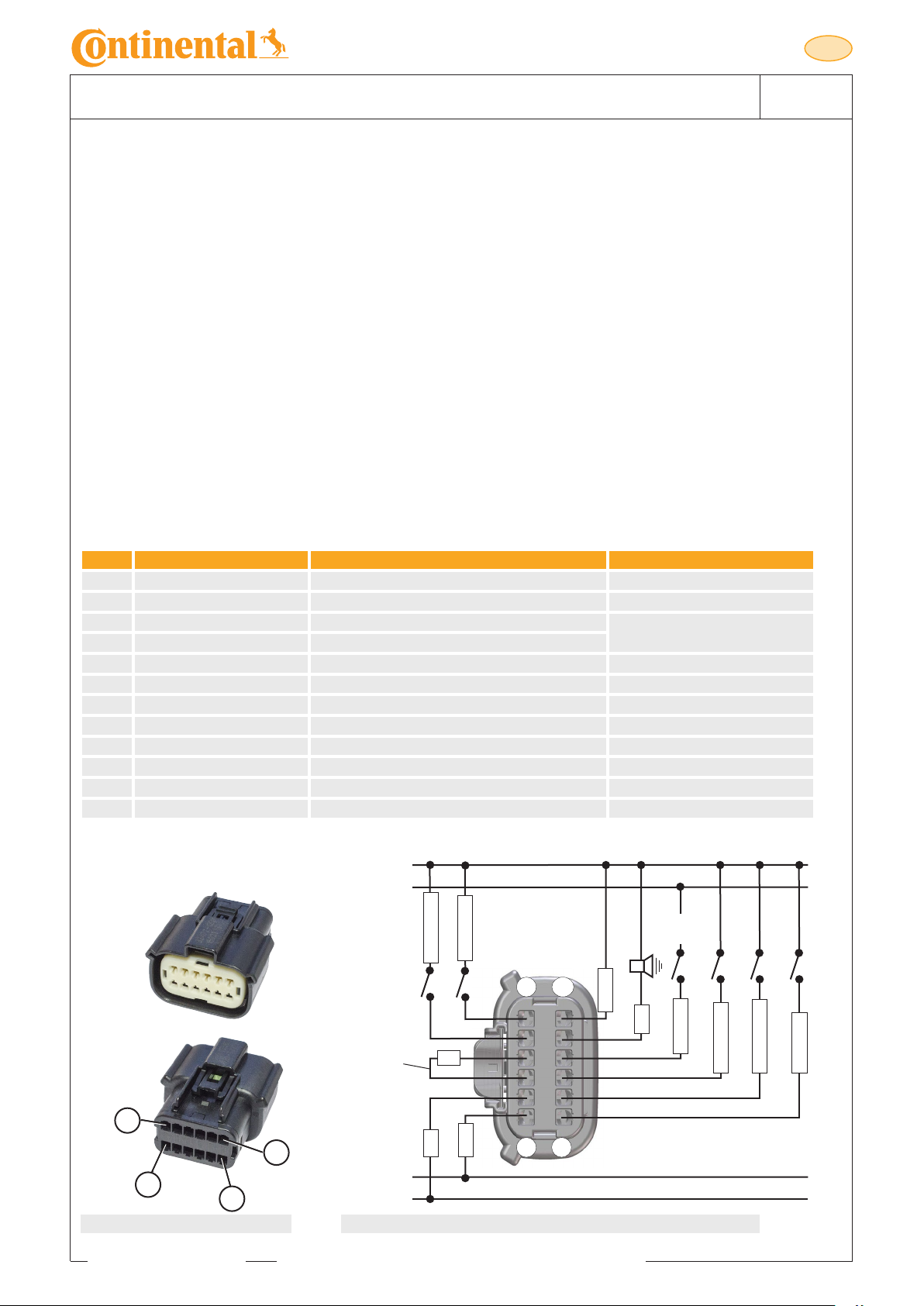
4. Composition and Functions
Figure 4.1 shows the composition of an 80mm gauge. Gauges with diameter 52mm have the same structure without having
a push-button and display.
Bezel
Reflector PCBDialDouble lens
Push-button Display Housing Damper Spinlock nutPointer Step motor
Fig. 4.1: Composition of a SingleViu gauge.
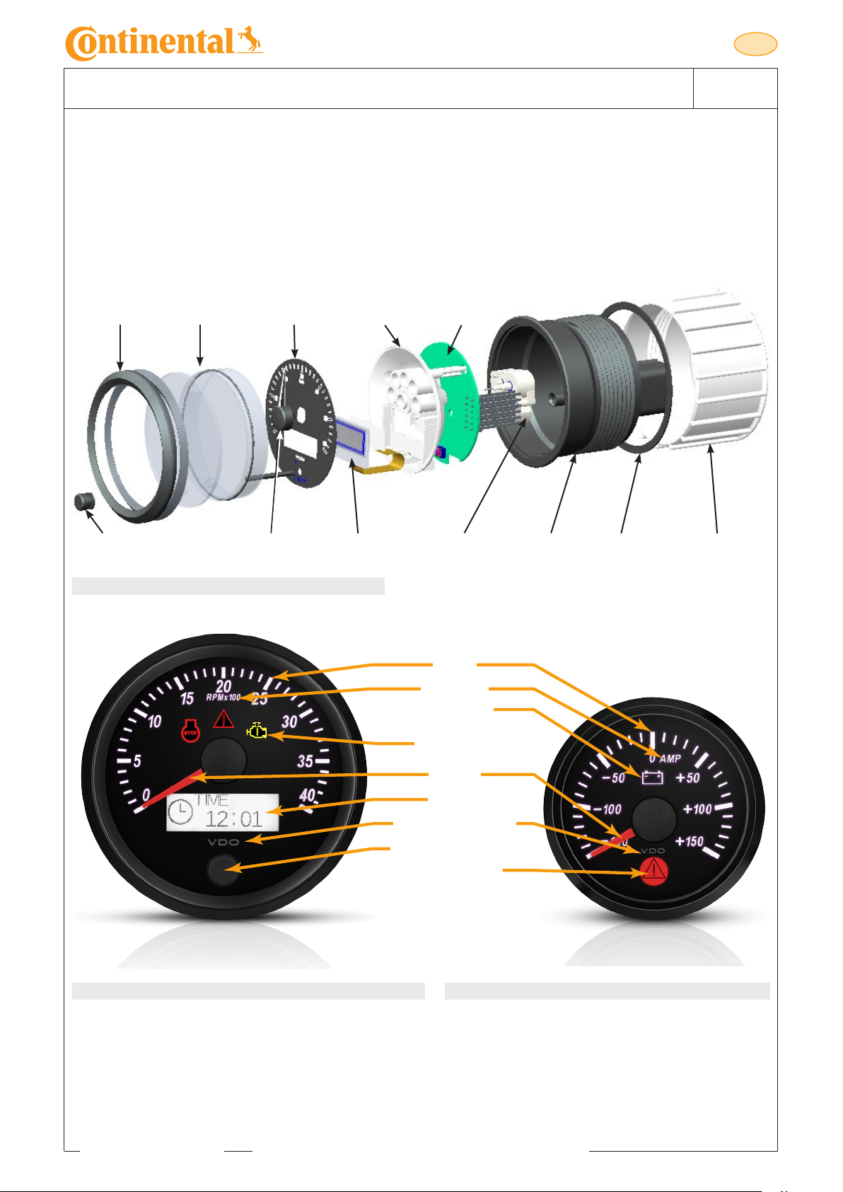
Scale
Scale unit
ISO symbol
Tell-tales 80
/ 100 mm
Pointer
Display
Manufacturer‘s sign
Internal push-button
Tell-tale 52 mm
TU00-0761-5207102
Fig. 4.2: Dial elements 80 and 100 mm Fig 4.3: Dial elements 52 mm
Version: 2.2 • 2018.01
Technische Änderungen vorbehalten – Technical details subject to change
Page 13

User Manual
EN
SingleViu
TM
13 - 40
4.1 Pointer
Main function of the gauge is to visualize a parameter which is sent via analog signal or CAN bus.
Pointer indication angle 240°
Pointer tolerance -3° to +3°, Speedometer 0° to 6°
4.2 Tell-tales
4.2.1 Tell-tale in gauges with diameter 52 mm
Gauges with diameter 52 mm contain a tell-tale, symbol 0434A acc. to ISO 7000 with red illumination.
Per default, the tell-tale will be activated for indication values beyond the scale limits. For level gauges, the lower warning
threshold is at a level of 10% and for the tachometer A2C38330300 at a rotational speed of 400 RPM.
All other warning thresholds are set to the scale limits by default.
Changes of the thresholds are possible using the ►ConfigTool.
4.2.2 Tell-tales in gauges with diameter 80 or 100 mm
SingleViu gauges with diameter 80 or 100 mm can be equipped with up to 5 tell-tales. Their positions on the dial are shown
in following picture.
Fig. 4.4: Layout of the tell-tales in gauges with 80 mm and
100 mm diameter.
Tell-tale 1 shows a warning triangle, symbol 0434A according to ISO 7000, with red illumination. It will be activated by indication values beyond overstepping a warning threshold. For tachometers, the lower activation threshold is 400 RPM. All
other warning thresholds are set to the scale limits by default. Changes of the thresholds are possible using the
►ConfigTool and by setting them in the extended ►configuration menu.
This tell-tale also serves as hazard lamp according to SAE J1939-73 und can be activated by pin 5 of the 12-pin connector
and by lamp status in CAN message DM1, SPN 987, PGN 65226 (since SW 01.06.03).
Tell-tale 2 shows a cylinder symbol with text “STOP”, symbol 1388 according to ISO 7000, with red illumination. This telltales serves as red stop lamp according to SAE J1939-73. It can be activated by pin 7 of the 12-pin connector and by lamp
status in CAN message DM1, SPN 1213, PGN 65226.
Per default, Tell-tale 2 is equipped in tachometers.
Tell-tale 3 shows a motor symbol, symbol 2423 according to ISO 7000, with yellow illumination. This tell-tale serves as malfunction indicator lamp according to SAE J1939-73. It can be activated by pin 6 of the 12-pin connector or by lamp status in
CAN message DM1, SPN 1213, PGN 65226.
Per default, tell-tale 3 is equipped in tachometers.
Tell-tales 4 and 5 are not equipped in platform gauge variants.
TU00-0761-5207102
Version: 2.2 • 2018.01
Technische Änderungen vorbehalten – Technical details subject to change
Page 14

User Manual
EN
SingleViu
TM
14 - 40
4.3 Display and push-button
SingleViu gauges with diameter 80 or 100 mm contain an internal display on which diverse information may be shown.
This information is organized in ►configuration menu and ►operation menu.
SingleViu gauges with diameter 80 or 100 mm contain an internal push-button to operate the display. An external push-button, which has to be connected to pin 10 of the 12-pin connector, has the same functionality.
4.3.1 Welcome logo
The welcome logo is a static picture that will be shown after every ignition for an adjustable time. Setting of the functionality
is possible in ►ConfigTool.
4.4 Illumination
All gauges of the SingleViu family can alter the brightness and color of their background illumination for dial and display if
available. This can be done by CAN message PGN 53503 / SPN 1487, by ►ConfigTool, or for devices with diameter 80 or
100 mm, also using the ►push-button.
In case of illumination setting by push-button, the device will broadcast a CAN message with PGN 53503. Byte 1 contains
SPN1487 for illumination brightness. Additionally, bytes 4 – 8 will be used for privately communicating the illumination color
to all other SingleViu gauges which are connected to the CAN bus.
Illumination
of the pointer
of the dial
of the display
red
RGB, default white
RGB, default white
4.5 Send indication value onto CAN
All gauges of the SingleViu family are able to broadcast the indication value as CAN message. They will use their prede-
fined source address as in ►variants overview and the default value for priority, SPN and PGN. All bytes other than the
SPN in the CAN message will be written as 0xFF.
This function is not available for the air pressure gauge and the cylinder temperature gauges.
4.6 External Buzzer
The digital output, pin 11 of the 12 pin connector, is linked to all ►tell-tales to attach an external buzzer or another electric
device. The predefined signal consists of 100 ms „ON“ and 400 ms „OFF“.
TU00-0761-5207102
Version: 2.2 • 2018.01
Technische Änderungen vorbehalten – Technical details subject to change
Page 15

User Manual
EN
SingleViu
TM
5. Variants overview
5.1 Variants 52 mm
Article number Gauge type Scale Analog input CAN input
Single packaging
A2C3833090001 A2C3833090025 Ammeter ISO 0247
A2C3833080001 A2C3833080025 Ammeter ISO 0247
A2C3833070001 A2C3833070025 Ammeter ISO 0247
A2C3833060001 A2C3833060025 Ammeter ISO 0247
A2C3832760001 A2C3832760025 Concentration DEF/AdBlue® ISO 2946 + "DEF"
A2C3833550001 A2C3833550025 Level DEF/AdBlue® ISO 0245 + "DEF"
A2C3832750001 A2C3832750025 Level DEF/AdBlue® ISO 0245 + "DEF"
A2C3833100001 A2C3833100025 Level Fuel ISO 0245
A2C3833110001 A2C3833110025 Level Fuel ISO 0245
A2C3833120001 A2C3833120025 Level Fuel ISO 0245
A2C3833130001 A2C3833130025 Level Fuel ISO 0245
A2C3833140001 A2C3833140025 Level Fuel ISO 0245
A2C3833150001 A2C3833150025 Level Fuel ISO 0245
A2C3916300001 A2C3916300025 Level Fuel ISO 0245
A2C3833440001 A2C3833440025 Pressure Air "AIR" 0 150 psi Resistance 10 - 184 Ω 5.1.10 n.a.
A2C3833450001 A2C3833450025 Pressure Brake ISO 1402
A2C3832710001 A2C3832710025 Pressure Brake ISO 1402
A2C3833480001 A2C3833480025 Pressure Brake ISO 1402
A2C3832730001 A2C3832730025 Pressure Brake ISO 1402
TU00-0761-5207102
A2C1800310001 A2C1800310025 Pressure Brake ISO 1405
A2C1800330001 A2C1800330025 Pressure Brake ISO 1406
A2C1800340001 A2C1800340025 Pressure Brake ISO 0238
A2C3833460001 A2C3833460025 Pressure Gear oil ISO 1167
A2C3832720001 A2C3832720025 Pressure Gear oil ISO 1167
A2C3833500001 A2C3833500025 Pressure Gear oil ISO 1167
Version: 2.2 • 2017.xx
OEM packaging
(25 pieces)
Gauge type Reference Scale symbol Min Max Unit Type Signal range
-30 +30 AMP Voltage -60 - +60 mV 5.1.1 65271 114 0x29
-60 +60 AMP Voltage -60 - +60 mV 5.1.2 65271 114 0x29
-100 +100 AMP Voltage -60 - +60 mV 5.1.3 65271 114 0x29
-150 +150 AMP Voltage -60 - +60 mV 5.1.4 65271 114 0x29
0 100 % n.a. 64923 3516 0x27
0 1 Resistance 3 - 180 Ω 5.1.5 65110 1761 0x27
E F Resistance 240 - 33.5 Ω 5.1.6 65110 1761 0x27
0 1 Resistance 3 - 180 Ω 5.1.5 65276 96 0x27
0 1 Resistance 90 - 5 Ω 5.1.7 65276 96 0x27
E F Resistance 3 - 180 Ω 5.1.5 65276 96 0x27
E F Resistance 240 - 33.5 Ω 5.1.6 65276 96 0x27
E F Resistance 0 - 90 Ω 5.1.8 65276 96 0x27
E F Resistance 90 - 5 Ω 5.1.7 65276 96 0x27
E F Voltage 0 - 5 V 5.1.9 65276 96 0x27
0 10 bar Resistance 10 - 184 Ω 5.1.11 65274 117 0x25
0 16 bar Voltage 0.5 - 4.5 V 5.1.12 65274 117 0x25
0 150 psi Resistance 10 - 184 Ω 5.1.10 65274 117 0x25
0 250 psi Voltage 0.5 - 4.5 V 5.1.13 65274 117 0x25
0 10 bar Voltage 0 - 5 V 5.1.35 65274 117 0x25
0 10 bar Voltage 0 - 5 V 5.1.35 65274 117 0x25
0 10 bar Voltage 0 - 5 V 5.1.35 65274 117 0x25
0 25 bar Resistance 10 - 184 Ω 5.1.14 65272 127 0x23
0 30 bar Voltage 0.5 - 4.5 V 5.1.15 65272 127 0x23
0 400 psi Resistance 10 - 184 Ω 5.1.16 65272 127 0x23
Technische Änderungen vorbehalten – Technical details subject to change
Sensor
curve
PGN SPN
15 - 40
CAN Source
address
Page 16

User Manual
EN
SingleViu
Article number Gauge type Scale Analog input CAN input
Single packaging
A2C3832740001 A2C3832740025 Pressure Gear oil ISO 1167
A2C3833160001 A2C3833160025 Pressure Engine oil ISO 0248
A2C3833170001 A2C3833170025 Pressure Engine oil ISO 0248
A2C3833230001 A2C3833230025 Pressure Engine oil ISO 0248
A2C3833190001 A2C3833190025 Pressure Engine oil ISO 0248
A2C3832690001 A2C3832690025 Pressure Engine oil ISO 0248
A2C3833240001 A2C3833240025 Pressure Engine oil "OIL" 0 150 psi Resistance 10 - 184 Ω 5.1.10 65263 100 0x22
A2C3833300001 A2C3833300025 Pressure Engine oil ISO 0248
A2C3832700001 A2C3832700025 Pressure Engine oil ISO 0248
A2C3833490001 A2C3833490025 Pressure Turbo ISO 2107
A2C3833470001 A2C3833470025 Pressure Turbo ISO 2107
A2C3833050001 A2C3833050025 Pyrometer ISO 1383 + "PYRO"
A2C3833040001 A2C3833040025 Pyrometer ISO 1383 + "PYRO"
A2C3833030001 A2C3833030025 Tachometer 0 40 RPM x 100 n.a. 61444 190 0x17
A2C3833520001 A2C3833520025 Temperature Cylinder 60 200 °C Resistance 482.5 - 14.3 Ω 5.1.27 n.a.
A2C3833530001 A2C3833530025 Temperature Cylinder 150 400 °F Resistance 482.5 - 14.3 Ω 5.1.28 n.a.
A2C3833510001 A2C3833510025 Temperature Hydraulic oil ISO 1414
A2C3916310001 A2C3916310025 Temperature Hydraulic oil ISO 1414
A2C3833380001 A2C3833380025 Temperature Engine oil ISO 2426
A2C3833390001 A2C3833390025 Temperature Engine oil ISO 1375
A2C3833410001 A2C3833410025 Temperature Engine oil ISO 2426
TU00-0761-5207102
A2C3833320001 A2C3833320025 Temperature Cooling water ISO 0246
A2C3833330001 A2C3833330025 Temperature Cooling water ISO 1380
A2C3833340001 A2C3833340025 Temperature Cooling water ISO 0246
A2C3833350001 A2C3833350025 Temperature Cooling water ISO 0246
A2C3832770001 A2C3832770025 Voltmeter ISO 0247
A2C3832780001 A2C3832780025 Voltmeter ISO 0247
Version: 2.2 • 2017.xx
TM
OEM packaging
(25 pieces)
Gauge type Reference Scale symbol Min Max Unit Type Signal range
0 500 psi Voltage 0.5 - 4.5 V 5.1.17 65272 127 0x23
0 5 bar Resistance 10 - 184 Ω 5.1.20 65263 100 0x22
0 10 bar Resistance 10 - 184 Ω 5.1.11 65263 100 0x22
0 80 psi Resistance 240 - 33.5 Ω 5.1.21 65263 100 0x22
0 80 psi Resistance 10 - 184 Ω 5.1.22 65263 100 0x22
0 10 bar Voltage 0.5 - 4.5 V 5.1.18 65263 100 0x22
0 150 psi Resistance 10 - 184 Ω 5.1.10 65263 100 0x22
0 150 psi Voltage 0.5 - 4.5 V 5.1.19 65263 100 0x22
0 2 bar Resistance 10 - 184 Ω 5.1.23 65270 102 0x24
0 60 psi Resistance 10 - 184 Ω 5.1.24 65270 102 0x24
0 1000 °C Voltage 4.1 - 37.7 mV 5.1.25 65270 173 0x30
0 2000 °F Voltage 4.1 - 37.7 mV 5.1.26 65270 173 0x30
40 120 °C Resistance 287.4 - 22.7 Ω 5.1.29 65128 1638 0x21
0 250 °F Resistance 287.4 - 22.7 Ω 5.1.30 65128 1638 0x21
50 150 °C Resistance 322.8 - 18.6 Ω 5.1.31 65262 175 0x19
50 150 °C Resistance 322.8 - 18.6 Ω 5.1.31 65262 175 0x19
100 300 °F Resistance 322.8 - 18.6 Ω 5.1.32 65262 175 0x19
40 120 °C Resistance 287.4 - 22.7 Ω 5.1.29 65262 11 0 0x18
40 120 °C Resistance 287.4 - 22.7 Ω 5.1.30 65262 11 0 0x18
100 250 °F Resistance 450 - 30 Ω 5.1.33 65262 110 0x18
100 250 °F Resistance 287.4 - 22.7 Ω 5.1.34 65262 110 0x18
8 16 VOLT Terminal 30 - 31 65271 168 0x28
16 32 VOLT Terminal 30 - 31 65271 168 0x28
Technische Änderungen vorbehalten – Technical details subject to change
Sensor
curve
PGN SPN
16 - 40
CAN Source
address
Page 17

User Manual
EN
SingleViu
TM
17 - 40
Sensor curves
The 52 mm gauges are preset to be supplied by a commercial sensor with common sensor curves. The sensor curves may
be changed via ►ConfigTool.
5.1.1 Sensor curve for Ammeter A2C38330600
Indication value [A] -150 -100 -50 0 50 100 150
Input value [mV] -60 -40 -20 0 +20 +40 +60
Characteristic curve predefined for shunt resistor A2C59514047 from Continental portfolio.
5.1.2 Sensor curve for Ammeter A2C38330700
Indication value [A] -100 -50 0 50 100
Input value [mV] -60 -30 0 +30 +60
Characteristic curve predefined for shunt resistor A2C59514045 from Continental portfolio.
5.1.3 Sensor curve for Ammeter A2C38330800
Indication value [A] -60 -40 -20 0 +20 +40 +60
Input value [mV] -60 -40 -20 0 +20 +40 +60
Characteristic curve predefined for shunt resistor A2C59514043 from Continental portfolio.
5.1.4 Sensor curve for Ammeter A2C38330900
Indication value [A] -30 -20 -10 0 +10 +20 +30
Input value [mV] -60 -40 -20 0 +20 +40 +60
Characteristic curve predefined for shunt resistor A2C59514041 from Continental portfolio.
5.1.5 Sensor curve for level gauge A2C38335500, A2C38331000, A2C38331200
Indication value 0 & E 1/8 1/4 3/8 1/2 5/8 3/4 7/8 1/1 & F
Input value [Ohm] 3 21 45 65 85 112 138 159 180
Characteristic curve predefined for Lever Type Level Sensors from Continental portfolio.
5.1.6 Sensor curve for level gauge A2C38327500, A2C38331300
Indication value E 1/8 1/4 3/8 1/2 5/8 3/4 7/8 F
Input value [Ohm] 240 197 153 128 103 85 68 51 34
5.1.7 Sensor curve for level gauge A2C38331100, A2C38331500
Indication value 0 1/8 1/4 3/8 1/2 5/8 3/4 7/8 1/1
Input value [Ohm] 75 66 57 48 39 30 21 12 3
Characteristic curve predefined for fuel level sensors with input value 75 Ohm at indication value zero.
5.1.8 Sensor curve for level gauge A2C38331400
Indication value E 1/8 1/4 3/8 1/2 5/8 3/4 7/8 F
Input value [Ohm] 0 11 23 34 45 56 68 79 90
Characteristic curve predefined for fuel level sensors with input value 75 Ohm at indication value E.
5.1.9 Sensor curve for level gauge A2C39163000
Indication value 0 1/8 1/4 3/8 1/2 5/8 3/4 7/8 1/1
Input value [Volt] 0,00 0,63 1,25 1,88 2,50 3,13 3,75 4,38 5,00
5.1.10 Sensor curve for Pressure gauge A2C38334400, A2C38334800, A2C38332400, A2C38333000
Indication value [psi] 0 20 30 50 70 80 100 120 130 150
Input value [Ohm] 10 39 53 79 104 116 139 160 170 188
Characteristic curve predefined for 10 bar pressure sensors from the Continental portfolio.
TU00-0761-5207102
5.1.11 Sensor curve for Pressure gauge A2C38334500, A2C38331700
Indication value [bar] 0 1 2 3 4 5 6 7 8 9 10
Input value [Ohm] 10 31 52 71 90 107 124 140 156 170 184
Characteristic curve predefined for 10 bar pressure sensors from the Continental portfolio.
Version: 2.2 • 2018.01
Technische Änderungen vorbehalten – Technical details subject to change
Page 18

User Manual
EN
SingleViu
5.1.12 Sensor curve for Pressure gauge A2C38327100
Indication value [bar] 0 2 4 6 8 10 12 14 16
Input value [Volt] 0,5 1 1,5 2 2,5 3 3,5 4 4,5
Characteristic curve predefined for 10 bar pressure sensors from the Continental portfolio.
5.1.13 Sensor curve for Pressure gauge A2C38327300
Indication value [bar] 0 25 50 75 100 125 150 175 200 225 250
Input value [Volt] 0,5 0,9 1,3 1,7 2,1 2,5 2,9 3,3 3,7 4,1 4,5
5.1.14 Sensor curve for Pressure gauge A2C38334600
Indication value [bar] 0 2,5 5 7,5 10 12,5 15 17,5 20 22,5 25
Input value [Ohm] 10 32 53 73 91 109 125 141 156 170 184
Characteristic curve predefined for 25 bar pressure sensors from the Continental portfolio.
5.1.15 Sensor curve for Pressure gauge A2C38327200
Indication value [bar] 0 5 10 15 20 25 30
Input value [Volt] 0,5 1,15 1,8 2,5 3,1 3,75 4,5
5.1.16 Sensor curve for Pressure gauge A2C38335000
Indication value [psi] 0 50 100 140 160 200 240 260 300 350 400
Input value [Ohm] 10 41 68 89 99 117 135 143 160 179 198
Characteristic curve predefined for 28 bar pressure sensors from the Continental portfolio.
TM
18 - 40
5.1.17 Sensor curve for Pressure gauge A2C38327400
Indication value [psi] 0 50 100 150 200 250 300 350 400 450 500
Input value [Volt] 0,5 0,9 1,3 1,7 2,1 2,5 2,9 3,3 3,7 4,1 4,5
5.1.18 Sensor curve for Pressure gauge A2C38326900
Indication value [psi] 0 1 2 3 4 5 6 7 8 9 10
Input value [Volt] 0,5 0,9 1,3 1,7 2,1 2,5 2,9 3,3 3,7 4,1 4,5
5.1.19 Sensor curve for Pressure gauge A2C38327000
Indication value [psi] 0 25 50 75 100 125 150
Input value [Volt] 0,5 1,15 1,8 2,5 3,1 3,75 4,5
5.1.20 Sensor curve for pressure gauge A2C38331600
Indication value [bar] 0 0,5 1 1,5 2 2,5 3 3,5 4 4,5 5
Input value [Ohm] 11 29 47 65 82 100 117 134 151 167 184
Characteristic curve predefined for 5 bar pressure sensors from the Continental portfolio.
5.1.21 Sensor curve for pressure gauge A2C38332300
Indication value [psi] 0 10 20 25 30 35 40 60 80
Input value [Ohm] 240 198 177 148 120 104 82 63 34
5.1.22 Sensor curve for pressure gauge A2C38331900
Indication value [psi] 0 10 20 30 40 50 60 70 80
Input value [Ohm] 11 36 60 84 108 132 155 178 201
Characteristic curve predefined for 5 bar pressure sensors from the Continental portfolio.
5.1.23 Sensor curve for pressure gauge A2C38334900
TU00-0761-5207102
Indication value [bar] 0 0,25 0,5 0,75 1 1,25 1,5 1,75 2
Input value [Ohm] 10 33 56 78 100 122 143 164 184
Characteristic curve predefined for 2 bar pressure sensors from the Continental portfolio.
5.1.24 Sensor curve for pressure gauge A2C38334700
Indication value [psi] 0 10 15 20 25 30 35 40 45 50 60
Input value [Ohm] 11 36 48 60 72 84 96 108 120 132 155
Characteristic curve predefined for 5 bar pressure sensors from the Continental portfolio.
Version: 2.2 • 2018.01
Technische Änderungen vorbehalten – Technical details subject to change
Page 19

User Manual
EN
SingleViu
5.1.25 Sensor curve for pyrometer A2C38330500
Indication value [°C] 0 125 250 375 500 625 750 875 1000
Input value [mV] 0 5 10 15 21 26 31 36 41
Characteristic curve predefined for pyrometer N03 320 264 from the Continental portfolio.
5.1.26 Sensor curve for pyrometer A2C38330400
Indication value [°F] 0 250 500 750 1000 1250 1500 1750 2000
Input value [mV] 0 5 11 16 22 28 34 40 45
Characteristic curve predefined for pyrometer N03 320 264 from the Continental portfolio.
5.1.27 Sensor curve for temperature gauge A2C38335200
Indication value [°C] 60 80 100 120 140 160 180 200
Input value [Ohm] 483 265 151 85 53 32 21 14
5.1.28 Sensor curve for temperature gauge A2C38335300
Indication value [°F] 150 175 200 225 250 275 300 325 350 375 400
Input value [Ohm] 422 271 189 127 83 61 44 30 23 17 12
5.1.29 Sensor curve for temperature gauge A2C38335100, A2C38333200, A2C38333300
Indication value [°C] 40 50 60 70 80 90 100 110 120
Input value [Ohm] 291 197 134 97 70 51 38 29 22
Characteristic curve predefined for thermistor 92-027-004 from the Continental portfolio.
TM
19 - 40
5.1.30 Sensor curve for temperature gauge A2C39163100
Indication value [°F] 0 50 80 100 110 125 125 150 175 200 225 250
Input value [Ohm] 500 500 500 320 257 257 185 112 71 47 31 22
Characteristic curve predefined for thermistor 92-027-004 from the Continental portfolio.
5.1.31 Sensor curve for temperature gauge A2C38333800, A2C38333900
Indication value [°C] 50 60 75 90 100 110 125 140 150
Input value [Ohm] 322 221 131 83 62 47 32 23 19
Characteristic curve predefined for thermistor 92-027-006 from the Continental portfolio.
5.1.32 Sensor curve for temperature gauge A2C38334100
Indication value [°F] 100 125 150 175 200 225 250 275 300
Input value [Ohm] 532 300 181 11 3 75 53 36 26 19
Characteristic curve predefined for thermistor 92-027-006 from the Continental portfolio.
5.1.33 Sensor curve for temperature gauge A2C38333400
Indication value [°F] 100 125 150 175 200 225 250
Input value [Ohm] 450 205 140 99 62 41 30
5.1.34 Sensor curve for temperature gauge A2C38333500
Indication value [°F] 100 125 150 175 200 225 250
Input value [Ohm] 320 185 112 71 47 31 22
Characteristic curve predefined for thermistor 92-027-004 from the Continental portfolio.
5.1.35 Sensor curve for Pressure gauge A2C18003100, A2C18003300, A2C18003400
Indication value [bar] 0 1 2 3 4 5 6 7 8 9 10
Input value [Volt] 0 0,5 1 1,5 2 2,5 3 3,5 4 4,5 5
TU00-0761-5207102
Version: 2.2 • 2018.01
Technische Änderungen vorbehalten – Technical details subject to change
Page 20

User Manual
EN
SingleViu
TM
5.2 Variants 80 mm
Article number Gauge type Scale Analog input CAN input
Single packaging
A2C3832910001 A2C3832910010 Speedometer 0 120 km/h Pulse L 65265 84 0xA7
A2C3832920001 A2C3832920010 Speedometer 0 140 mph Pulse L 65265 84 0xA7
A2C3832930001 A2C3832930010 Speedometer 0 160 mph Pulse L 65265 84 0xA7
A2C3832940001 A2C3832940010 Speedometer 0 200 km/h Pulse L 65265 84 0xA7
A2C3832950001 A2C3832950010 Speedometer 0 300 km/h Pulse L 65265 84 0xA7
A2C3832880001 A2C3832880010 Speedometer 0 30 mph Pulse L 65265 84 0xA7
A2C3832890001 A2C3832890010 Speedometer 0 60 km/h Pulse L 65265 84 0xA7
A2C3832900001 A2C3832900010 Speedometer 0 90 mph Pulse L 65265 84 0xA7
A2C3832960001 A2C3832960010 Tachometer 0 20 RPM x 100 Pulse L 61444 190 0x17
A2C3832970001 A2C3832970010 Tachometer 0 25 RPM x 100 Pulse L 61444 190 0x17
A2C3832980001 A2C3832980010 Tachometer 0 30 RPM x 100 Pulse L 61444 190 0x17
A2C3832990001 A2C3832990010 Tachometer 0 40 RPM x 100 Pulse L 61444 190 0x17
OEM packaging
(10 pieces)
Min Max Unit Type
Sensor
curve
PGN SPN
CAN source
address
20 - 40
A2C3833000001 A2C3833000010 Tachometer 0 50 RPM x 100 Pulse L 61444 190 0x17
A2C3833010001 A2C3833010010 Tachometer 0 60 RPM x 100 Pulse L 61444 190 0x17
A2C3833020001 A2C3833020010 Tachometer 0 80 RPM x 100 Pulse L 61444 190 0x17
5.2.1 Sensor curve for 80 mm and 100 mm gauges
The indication value is linear to the number of pulses respectively the frequency of the input signal – “L” in the table above.
For tachometers this proportionality factor be chosen between 0.1 and 999.9 pulses may. Default is a number of 6 pulses
per motor turn.
For speedometers this proportionality factor be chosen between 1 and 65535. Default is a number of 8000
pulses per kilometer for metric speedometers and 8000 pulses per mile for mph speedometers.
5.3 Variants 100 mm
Article number Gauge type Scale Analog input CAN input
Single packaging
A2C3832860001 A2C3832860010 Speedometer 0 120 km/h Pulse L 65265 84 0xA7
A2C3832850001 A2C3832850010 Speedometer 0 140 mph Pulse L 65265 84 0xA7
A2C3832840001 A2C3832840010 Speedometer 0 200 km/h Pulse L 65265 84 0xA7
A2C3832830001 A2C3832830010 Speedometer 0 300 km/h Pulse L 65265 84 0xA7
A2C3832870001 A2C3832870010 Speedometer 0 90 mph Pulse L 65265 84 0xA7
A2C3832820001 A2C3832820010 Tachometer 0 25 RPM x 100 Pulse L 61444 190 0x17
OEM packaging
(10 pieces)
Min Max Unit Type
Sensor
curve
PGN SPN
CAN source
address
A2C3832810001 A2C3832810010 Tachometer 0 30 RPM x 100 Pulse L 61444 190 0x17
A2C3832800001 A2C3832800010 Tachometer 0 40 RPM x 100 Pulse L 61444 190 0x17
A2C3832790001 A2C3832790010 Tachometer 0 50 RPM x 100 Pulse L 61444 190 0x17
TU00-0761-5207102
5.4 Package content
The single packaging contains each a gauge including the spinlock nut and safety instructions. The OEM-packaging with 52
mm gauges contains 25 sets of pieces.
The OEM packaging with 80 or 100 mm gauges contains 10 sets of pieces.
Further ►accessories are available separately.
Version: 2.2 • 2018.01
Technische Änderungen vorbehalten – Technical details subject to change
Page 21

User Manual
EN
SingleViu
TM
6. Handling and Mounting instruction
6.1 Transportation and storage
Transport and store the device always in its packaging. Handle with care.
The allowed storage Temperature range is -40 °C to +85 °C (-40 °F to +185 °F), recommendation is storage at room
temperature. Protect from dust and moisture.
Without ►connector the gauge is not tight against dust and fluids.
» Perform the ►configuration before mounting the gauge.
6.2 Disconnect the power supply
Danger of battery short circuits!
Short circuits can cause cable fires, battery explosions and damage to other electronic systems.
• Remove voltage sources before electrical work.
• Remove ground cables of starter batteries and separate batteries.
• Protect battery from being inadvertently reconnected.
21 - 40
REMARK:
All data from volatile electronic memories in other device will be lost and need to be reprogrammed later.
» Turn-off ignition and remove the ignition key.
» If necessary, remove the main circuit switch.
» Disconnect the negative terminal on all batteries.
6.3 Prepare the mounting space
Danger of inadequate mounting position!
Wrong mounting position of the gauge may affect other systems or the vehicle stability.
• The instrument must not impair the driver’s field of vision.
• Do not install the instrument in the mechanical and electrical airbag area.
• Do not drill holes or ports in load-bearing or stabilizing stays or tie bars.
• Note the magnetic safe distance to the compasses. Recommendation: Minimum 30 cm.
Fig. 6.1: Ignition off Fig. 6.2: Disconnect battery
REMARK:
The panel has to be sufficiently stabile and between 2 and 16 mm thick. The device may be mounted in
any orientation between 0° and 90° according to DIN 16257.
TU00-0761-5207102
» Choose proper mounting location.
» If need be, prepare the mounting hole, e.g. in the dash board.
Version: 2.2 • 2018.01
Technische Änderungen vorbehalten – Technical details subject to change
Page 22

User Manual
EN
SingleViu
Hole dimensions must comply to following values:
52 mm 52 + 0.5 mm 110 mm
80 mm 80 + 1 mm or 85 + 1 mm 110 mm
100 mm 100 + 1 mm 110 mm
Gauges with diameter 80 mm can be mounted in holes
with diameter 85 mm.
» Use the spinlock nut with centering lip ahead
as shown in the picture 6.6.
TM
Hole diameter Assembly depth
22 - 40
Ø 53 / 81/86 / 101 mm
110 mm
Fig. 6.3: Hole dimensions
• Pay attention to how lines and cable harnesses are laid so that you do not damage them.
• Drill small ports; enlarge and complete them, if necessary, using taper milling tools, saber saws, keyhole saws or files. Deburr edges.
» If need be, lay the needed cables.
REMARK:
Cable strength acc. Molex requirement 1.20 – 2.69 mm in order to ensure tightness.
http://www.molex.com/pdm_docs/ps/PS-33472-000.pdf
Danger of sudden loss of vehicle functionality!
Faulty connections or unsuitable routing can cause short circuits or failure of other components, possibly
after long time of operation.
• Only use fused voltage supply. Recommendation: 5 Amp fuse.
• Use cables with sufficient cross-sectional area and insulation.
• When installing electrical cables, use the provided cable ducts and harnesses; however, do not run
cables parallel to ignition cables or to cables that lead to large electricity consumers.
• Fasten cables with cable ties or adhesive tape. Do not run cables over moving parts. Do not attach
cables to the steering column. Ensure that cables are not subject to tensile forces.
• If cables are run through drill holes, protect them using rubber sleeves or the like.
• Use only a soft soldering process or commercially available crimp connector to create new cable
connections.
• Make crimp connections with cable crimping pliers only.
• Insulate exposed stranded wires to prevent short circuits
TU00-0761-5207102
6.4 Mounting of the connector
SingleViu uses the connector system MX150 of company MOLEX.
REMARK:
Detailed information on the MOLEX system MX150 like drawings, product specification, mounting
instruction, crimp instruction: http://www.molex.com/ind/mx150.html.
Version: 2.2 • 2018.01
Technische Änderungen vorbehalten – Technical details subject to change
Page 23

User Manual
EN
SingleViu
Use only a cable stripper to strip the cable and adjust it so that stranded wires are not damaged or separated
TM
REMARK:
The MOLEX product family MX150 contains different crimping contacts in series 33012. When choosing the
contact be aware to have a tinned surface and the correct diameter of cables for according size classes.
http://www.molex.com/molex/products/listview.jsp?channel=products&sType=s&query=33012
The MOLEX recommendation for sealed connectors is 33012-2004 or 33012-3004.
» Attach the crimp contacts onto the cable ends.
» Connect the cables according to the following pinning to be MOLEX connectors.
Refer to chapter 3.4 for wiring diagrams.
8 pin connector, MOLEX 334724801, for all gauges:
Pin Description Remark
1 Terminal 30 Battery Plus (12/24 V
2 Terminal 31 Battery Minus (Ground)
3 Sensor ground Ground reference for sensor signal
4 Terminal 15 Ignition
5 Sensor input Contact for analog sensor signal
6 Terminal 58 Illumination
7 CAN High Input for CAN bus SAE J1939
8 CAN Low Input for CAN bus SAE J1939
DC
)
1
23 - 40
4
12 pin connector, MOLEX 334721201, for gauges
with diameter 80 or 100 mm:
Pin Description Remark
1 CAN High Opt. input for CAN bus SAE J1939
2 CAN Low Opt. input for CAN bus SAE J1939
3 Termination resistance CAN termination resistance 120 Ohm
4 Termination resistance CAN termination resistance 120 Ohm
5 Digital input 1 Control of tell-tale 1
6 Digital input 2 Control of tell-tale 2
7 Digital input 3 Control of tell-tale 3
8 Digital input 4 Control of tell-tale 4
9 Digital input 5 Control of tell-tale 5
10 Digital input 6 Connection for external push-button
11 Digital output 1 Connection for external buzzer
12 Digital input 7 Configuration pin
TU00-0761-5207102
» Close unused positions with blanking plug, MOLEX 34345-0001, or use
suitable MOLEX mat seal with blocked terminals.
»
Level of protection IP67 will only be achieved if all connector positions occupied
or closed with blanking plug.
Without connector, the gauge reaches protection level IP40.
5
Fig. 6.4: MOLEX 8-pin
connector
8
1
7
12
Fig. 6.5: MOLEX 12-pin
connector
6
Version: 2.2 • 2018.01
Technische Änderungen vorbehalten – Technical details subject to change
Page 24

User Manual
EN
SingleViu
TM
6.5 Mounting the gauge
» Put the gauge into the mounting hole and turn it into intended orientation.
REMARK:
Make sure that the seal lays untwisted
between the panel and the front ring.
» Orientate the spinlook nut 80/85 mm
with centering lip ahead.
» Hand-tighten the spinlock nut,
max. 4 Nm (400 Ncm).
» Put on the connector onto the gauge until it audibly locks.
24 - 40
Fig. 6.6: Mount the gauge.
6.6 Reconnect the power supply
Danger of defect or disabled systems!
Vehicle components may have been harmed or disconnected unintentionally.
Functionality failures of one system endangers the safety of the whole vehicle /
machine.
• Check indication values of the gauge for plausibility.
• Check other components of vehicle/machine for functionality.
» Reconnect the battery after inspecting the connection.
» If necessary, reinsert the main circuit switch. Turn on the ignition and
conduct a functional test of the device and the whole vehicle.
TU00-0761-5207102
» Reprogram all device that lost their data in volatile memories.
Fig. 6.7: Plug in connector.
Fig. 6.8: Connect battery.
Version: 2.2 • 2018.01
Fig. 6.9: Ignition on.
Technische Änderungen vorbehalten – Technical details subject to change
Page 25

User Manual
EN
SingleViu
TM
7. Configuration and initial setup
The SingleViu gauges are programmed for analog operation mode per default and can be directly used in many
cases. Please refer to chapter 4, technical data, for details, e.g. for sensor curves. A configuration may be necessary
nonetheless to adopt the functionality to the specific vehicle or individual preferences, e.g. for operation via CAN bus.
7.1 Configuration via SingleViu ConfigTool
The SingleViu ►ConfigTool is a computer program to easily parametrize
the SingleViu gauges. The ConfigTool can be provided by your ►VDO-
Partner.
7.1.1 Prerequisites and preparation
The SingleViu ConfigTool is a computer
program that requires the operating system Windows 7, Windows 8 or Windows
10 with .NET in version 4.5.2 or higher.
Administrator rights are required to execute the installer file.
» Unzip and start the file.
» Follow the user menu.
The ConfigTool is installed in the select-
ed register and is applicable immediately. The desktop-icon helps starting the
Config-Tool easily.
Configuring of SingleViu gauges occurs
via Unified Diagnostic Services (UDS)
according to ISO 14229. The ConfigTool
is programmed for usage with ►CAN
boxes of companies Vector and PeakSystems, that need to be installed separately.
25 - 40
Fig. 7.1: Setup
Configurations will be stored as files with filename extension „.acg“. Per default all factory settings of all gauges are
available and stored using the part number. Own configuration can be added.
The configuration of the gauges before mounting into the vehicle is recommended. During configuration only one
gauge may be connected to the CAN bus; thus it must be performed for every single gauge individually.
For configuration use the “SingleViu Programming/Test cable” from ►Accessories.
Proceed as follows:
» Start the gauge
• Connect the brown cable (terminals 30, 15 and 58; battery plus, ignition and illumination) to DC voltage plus,
nominal voltage 12 or 24 Volts.
• Connect the black cable (terminal 31, ground) to DC voltage minus.
• Put on the connector onto the gauge until it audibly locks.
» Prepare the CAN connection.
• Connect the Sub-D via 120 Ohm termination to the CAN box.
• Connect the CAN box with the computer.
» Start the ConfigTool by clicking the program file on desktop or in start menu.
TU00-0761-5207102
Version: 2.2 • 2018.01
Technische Änderungen vorbehalten – Technical details subject to change
Page 26

User Manual
EN
SingleViu
7.1.2 The user mask
The user mask consists of following items:
TM
26 - 40
Fig. 7.2: Examplary illustration of the ConfigTool user mask. The set of items depends on gauge variant.
Basic functions
The menu item „File“ offers following activities:
• Open: Load an existing configuration.
Only such co nfiguration can be loaded that comply to the current gauge.
• New: Only in offline mode: Load a default configuration and edit.
• Save: Store the current configuration under current filename.
• Save as ...: Store the current configuration under another filename.
• Close: Only in offline mode: Close the current configuration.
• Quit: Close the ConfigTool.
The menu item „Options“ offers following activities:
• Logging level: Advanced users select a level of additional information on usage
of the ConfigTool.
• Language: Select the language for the ConfigTool. A change of the selected
language will be applied after restart of the ConfigTool. There are
the languages English (default), German and French available.
The menu item „?“ offers following activities:
• Help: This chapter of the user manual will be opened.
• About ...: Information on the ConfigTool.
TU00-0761-5207102
CAN connection
The red or green status indication „offline“ / „online“ shows the current CAN connection status.
The button „Connect“ / „Disconnect“ allows to start or to finish a connection with the CAN bus.
Version: 2.2 • 2018.01
Technische Änderungen vorbehalten – Technical details subject to change
Page 27

User Manual
EN
SingleViu
TM
Dongle
The dongle status shows if a ►dongle is connected and displays its workshop number.
General gauge data
General gauge information of the current SingleViu gauge is shown in this area. This includes a dial picture, the gauge
type, the product part number of the unpacked gauge and the version numbers of hardware and firmware.
Read / Write
The upload-button (Read) is to load the current device configuration from the device and display it in the user mask.
The download-button (Write) is to store the current configuration from the user mask into the device.
In case of unconnected CAN bus or unchanged configuration, these two buttons will be deactivated.
Basic settings
Brightness [%]
The brightness of the background illumination of dial and display can be adapted in the range of 0% for no illumination
to 100% for full illumination brightness. Default setting is 80%.
Dial
The color of the dial’s background illumination can be changed. The drop-down menu provides the predefined options
white (default), amber, red, yellow, blue and green.
27 - 40
Display
For gauges with display, the color of its background illumination can be changed. The drop-down menu provides the
predefined options white (default), amber, red, yellow, blue and green.
Warning thresholds
The lower and the upper warning thresholds for the internal tell-tale can be changed. At indication values beyond
these thresholds, the ►tell-tale 1 is activated. Deactivation is deferred by the settable hysteresis value.
Welcome logo
For gauges with display, a path to a bitmap file may be chosen to upload it as welcome logo. This picture must be a
monochrome bitmap file with resolution 132 x 43 pixels. With activated checkbox the picture will be downloaded in
next write sequence.
The duration for displaying the Welcome logo in seconds after ignition can be selected. At the maximum value of 255,
the welcome logo will be displayed permanently.
Data Source
Signal source
Per drop-down menu it can be chosen if data shall be provided via ►CAN bus SAE J1939 or if an analog value shall
be read. The tachometer A2C38330300 can only be operated in CAN mode.
Pulses per turn (tachometers) or per kilometer (speedometers)
This function is active for tachometers and speedometers with diameter 80 or 100 mm.
The number of pulses per motor turn, per kilometer or per mile must be entered.
Possible values are 0.5 to 999.9 pulses per motor turn and 20 to 400,000 pulses per kilometer.
Danger of wrong speed indication value!
TU00-0761-5207102
A wrong setting leads to wrong indication value of motor rotational speed or vehicle speed for the driver. This
may result in dangerous driving situations. Also the operating license may become invalid.
• Type in the correct number of pulses for the vehicle at hand.
• If need be, evaluate the number of pulses beforehand or look it up in the sensor documentation
• Operate the gauge only in analog mode if correct number of pulses is known
Version: 2.2 • 2018.01
Technische Änderungen vorbehalten – Technical details subject to change
Page 28

User Manual
EN
SingleViu
Message PV onto CAN
When this function is selected, the gauge will send the imported value onto ►CAN bus. This function is not available
for tachometers.
Pointer damping
This value parametrizes the PT1 filter for pointer agility damping.
Sensor curve
The predefined ►sensor curve is configured for main relevant sensors. The sensor curve still can be adapted by setting the analog input value.
This function is activated only in analog mode for gauges with potentially non-linear sensor curve that is with resistive
analog input.
TM
Display content settings
This subsection will be shown only for gauges will display.
Unit system
It is possible to select if the displayed values shall be in metric units (default in gauges with metric dial scale) or in US
customary units (default in speedometers with miles per hour).
Clock mode
It is possible to select between 24-hour (default) and 12-hour clock mode.
28 - 40
Content of the operation menu
The menu items can be included or excluded by checking or unchecking the corresponding box.
REMARK:
The predefined menus differ between speedometers and tachometers.
Please refer to chapter 6.2 and 6.3 for details.
REMARK:
Some items can be internally calculated by the gauge and will be available in analog mode also.
Other data can only be obtained from the CAN bus.
Presetting the hour counter (tachometers) and the odometer (speedometers)
In analog mode, tachometers calculate the total operation hours and speedometers calculate the total odometer. This
internal value can be updated.
This function is only available for authorized workshops with ►dongle. The odometer value is to be entered in the
selected unit system, either Kilometer or Miles.
TU00-0761-5207102
Version: 2.2 • 2018.01
Technische Änderungen vorbehalten – Technical details subject to change
Page 29

User Manual
EN
SingleViu
TM
7.2 Configuration via push-button
(only for gauges with diameter 80 or 100 mm)
Some certain settings can be configured via internal ►push-button or an external button, pin 10 of the 12-pin connector.
Therefore the gauge provides a configuration menu consisting of 5 items. This menu allows the driver to set comfort
functions.
For the initial configuration an extension to the configuration menu with three additional items is available. These settings may not be altered in regular operation. To access this menu, connect pin 12 of the 12-pin connector to battery
plus.
Danger of wrong speed indication value!
A wrong setting leads to wrong indication value of motor rotational speed or vehicle speed for the driver. This
may result in dangerous driving situations. Also the operating license may become invalid.
• Set the correct number of pulses for the vehicle at hand.
• If need be, evaluate the number of pulses beforehand or look it up in the sensor documentation
• Operate the gauge only in analog mode if correct number of pulses is known.
• Perform this initial configuration on workbench and not within the vehicle.
• Remove the contact to pin 12 after initial configuration. Do not keep this pin connected in regular operation.
Procedure to access the configuration menu:
» Power the gauge which means to connect terminal 30/31 to DC voltage, nominal value 12 or 24 V.
» if need be, switch-off terminal 15.
» only for initial configuration: connect pin 12 of 12-pin connector to voltage supply, (terminal 30).
» press and hold the key.
» switch-on terminal 15.
» release the key.
29 - 40
Procedure to exit the configuration menu:
» Wait for 30 seconds without button press. The configuration menu will be closed and the gauge starts regular oper-
ation mode.
Or
» Switch-off ignition (terminal 15) and restart without pressing the button.
General instruction:
A short button press („SP“, < 2sec.) changes the momentarily shown value.
A long button press („LP“, > 2sec.) switches to be next item.
TU00-0761-5207102
Version: 2.2 • 2018.01
Technische Änderungen vorbehalten – Technical details subject to change
Page 30

User Manual
EN
SingleViu
7.2.1 Units
Per default, the metric system is selected for display
information values.
It can be changed into US customary units and back.
Gauges with explicitly US customary units on the dial
scale are configured accordingly.
7.2.2 Clock
Per default, the 24-hour clock mode is selected.
It can be changed it into the 12-hour clock mode and
back.
7.2.3 Brightness
Per default, 80% brightness is selected.
It can be changed in 10% steps.
7.2.4 Color oft the dial background illumination
Per default, a white background illumination is selected. It can be changed into several other predefined
colors.
TM
UNITS
metric
SP
CLOCK
24 h
SP
BRIGHT
80 %
SP
DIAL
white
SP
30 - 40
SP = Short press (< 2 sec.)
LP = Long press (> 2 sec.)
LP
LP
LP
LP
LP
LP
LP
LP
UNITS
metric
CLOCK
24 h
BRIGHT
DIAL
white
0 %
SP
SP
SP
SP
UNITS
U.S.
CLOCK
12 h
SP
BRIGHT
100 %
SP
DIAL
green
7.2.5 Color of display background illumination
Per default, a white background illumination is selected. It can be changed into several other predefined
colors.
Only at initial setup
7.2.6 Selection of signal source
Per default, the analog signal source is selected. It
can be changed to CAN input and back.
7.2.7 Setting the number of pulses
In case of analog input, the correct number of pulses
must be set. Default values are 6 pulses per motor
turn for tachometers and 8,000 pulses per kilometer
for speedometers (12875 pulses per mile).
Possible values are 0.5 to 999.9 pulses per motor
turn and 20 to 99,999 pulses per kilometer.
7.2.8 Setting the warning thresholds
Upper and lower thresholds to activate the warning
tell-tale can be set. Default values are the scale lim-
TU00-0761-5207102
its. Lower default threshold for tachometers is 400
RPM.
DISPLAY
white
SP
SOURCE
CAN
SP
PULSES
08000
SP
ALARM Hi
3000
SP
SP
LP
LP
LP
LP
LP
DISPLAY
white
SOURCE
CAN
PULSES
08000
LP
SP SP
PULSES
18000
LP
ALARM Hi
3000
LP
SP SP
ALARM Hi
4000
SP
LP
LP
SP
DISPLAY
green
SOURCE
analog
PULSES
13570
PULSES
13571
ALARM Hi
4100
ALARM Hi
4101
Version: 2.2 • 2018.01
ALARM Lo
LP
0400
LP
SP
Technische Änderungen vorbehalten – Technical details subject to change
ALARM Lo
0400
SP SP
ALARM Lo
LP
1400
ALARM Lo
4100
ALARM Lo
4101
Page 31

User Manual
EN
SingleViu
TM
8. Operating menu
General instruction:
A short button press („SP“, < 2sec.) switches to the next menu item of increments the momentarily shown value.
A long button press („LP“, > 2sec.) switches to the change mode, within a change mode to the next digit or back to the
menu.
8.1 Operating menu for gauge with diameter 52 mm
SingleViu gauges with diameter 52 mm show the according indication value and possibly a warning signal but do not
contain any functionality for user operation.
8.2 Operating menu for speedometers
(diameter 80 and 100 mm)
At every ignition it is possible to start the ►configuration menu by pressing the button.
Otherwise and if applicable the ►welcome logo will be shown.
Afterwards the display content changes to regular operation menu. Its items may freely selected and arranged in
►ConfigTool. Below the default operation menu is explained.
SP = Short press (< 2 sec.)
8.2.1 Odometer
Analog mode: Internal calculation
CAN mode: PGN 65248 / SPN 245
8.2.2 Trip odometer
Analog mode: Internal calculation
CAN mode: PGN 65248 / SPN 244
8.2.3 Time
Analog mode: Internal calculation
CAN mode: PGN 65254 / SPN 960 and 961
In analog mode the clock needs to be set after every
ignition.
Short press
ODO
123456
SP
TRIP
123.4
SP
TIME
12:34
SP
km
km
LP = Long press (> 2 sec.)
LP
LP
LP
LP
BRIGHT
TRIP
TIME
15:08
SP
LP
TIME
20:08
0 %
0.0
SP
SP
BRIGHT
Analog mode only:
LP to reset the trip
km
odometer.
LP
TIME
TIME
20:08
SP
20:20
31 - 40
100 %
8.2.4 Instantaneous fuel economy
CAN mode only: PGN 65266 / SPN 184
8.2.5 Average fuel economy
CAN mode only: PGN 65266 / SPN 185
8.2.6 Instantaneous fuel rate
CAN mode only: PGN 65266 / SPN 183
8.2.7 Average fuel rate
CAN mode only: PGN 65203 / SPN 1029
8.2.8 Power take out
TU00-0761-5207102
CAN mode only: PGN 65265 / SPN 976
8.2.9 Failure messages DM1
CAN mode only: PGN 65226
Version: 2.2 • 2018.01
ECO
l/100km
12.3
SP
Ø ECO
l/100km
12.3
SP
RATE
l/h
12.3
SP
Ø RATE
l/h
12.3
SP
PTO
25
SP
DM1
LP
1 DTC
Technische Änderungen vorbehalten – Technical details subject to change
SPN 190
FMI 0
OC 2
SP
SPN 168
FMI 1
OC 3
Page 32

User Manual
EN
SingleViu
TM
8.3 Operating menu for tachometers
(diameter 80 and 100 mm)
At every ignition it is possible to start the ►configuration menu by pressing the button.
Otherwise and if applicable the ►welcome logo will be shown.
Afterwards the display content changes to regular operation menu. Its items may freely selected and arranged in
►ConfigTool. Below the default operation menu is explained.
SP = Short press (< 2 sec.)
LP = Long press (> 2 sec.)
8.3.1 Total hour counter
Analog mode: Internal calculation
CAN mode: PGN 65253 / SPN 247
8.3.2 Trip engine running time
CAN mode only: PGN 65200 / SPN 1036
8.3.3 Time
Analog mode: Internal calculation.
CAN mode: PGN 65254 / SPN 960 and 961
In analog mode the clock needs to be reset after
every power switch-off.
Short press
EHC
1234.5
SP
TRIP
123.4
SP
TIME
12:34
SP
LP
h
LP
h
LP
BRIGHT
TIME
15:08
SP
LP
TIME
20:08
SP
SP
0 %
LP
32 - 40
BRIGHT
100 %
TIME
20:08
SP
TIME
20:20
8.3.4 Current gear
CAN mode only: PGN 61445 / SPN 523
8.3.5 Recommended gear
CAN mode only: PGN 65195 / SPN 1113
8.3.6 Instantaneous fuel rate
CAN mode only: PGN 65266 / SPN 183
8.3.7 Average fuel rate
CAN mode only: PGN 65203 / SPN 1029
8.3.8 Failure messages DM1
CAN mode only: PGN 65226
TU00-0761-5207102
CURRENT
Gear 1
SP
RECOMM
Gear 2
SP
RATE
12.3
SP
Ø RATE
12.3
SP
DM1
1 DTC
l/h
l/h
LP
SPN 190
FMI 0
OC 2
SP
SPN 168
FMI 1
OC 3
Version: 2.2 • 2018.01
Technische Änderungen vorbehalten – Technical details subject to change
Page 33

User Manual
EN
SingleViu
TM
9. Replacement of gauges of predecessor series
SingleViu gauges can technically replace most of the devices of the predecessor series Viewline, World Wide Gauges
and CANcockpit.
» For the electrical connection of a SingleViu gauge to your existing cable harness you may use the corresponding
adapter cable.
Level of protection IP67 will only be achieved if all connector positions occupied or closed with blanking plug
MOLEX 34345-0001.
REMARK:
In case of totally unoccupied 12-pin-connector, the blind connector MOLEX 33472-1258 can be used.
9.1 Replacement of Viewline
» Connect the adapter cable „SingleViu Adapter cable Viewline 8pin“, part number 2910000301300, with the
SingleViu gauge and the vehicle 8-pin-connector.
» Put on the connector onto the gauge until it audibly locks.
33 - 40
Fig. 9.1: SingleViu Adapter cable Viewline 8pin
In case of SingleViu gauges with diameter 80 or 100 mm it is possible to connect an external button and an alarm output, equally as in the Viewline gauge which is to be replaced.
» To do so, connect the adapter cable „SingleViu Adapter cable Viewline 14pin“, part number 2910000301400, with
the SingleViu gauge and the vehicle 14-pin-connector.
» Put on the connector onto the gauge until it audibly locks.
In difference to Viewline the external push-button has to be connected to terminal 31, refer to the wiring diagram, fig.
3.4.
» Connect the extern push-button accordingly.
TU00-0761-5207102
Fig. 9.2: SingleViu Adapter cable Viewline 14pin
Version: 2.2 • 2018.01
Technische Änderungen vorbehalten – Technical details subject to change
Page 34

User Manual
EN
SingleViu
TM
9.2 Replacement of World Wide Gauges (WWG; Cockpit international, Cockpit Vision)
SingleViu gauges can technically replace the electrical gauges of the WWG platform. For the electric contact, please
use the adapter cable „SingleViu Adapter cable WWG“, part number 2910000301500.
The wires are color coded as follows:
Red: Battery plus (terminal 30)
Black: Ground (terminal 31)
Brown: Ignition (terminal 15)
Blue: Sensor ground
Green: Sensor signal
Red-blue: Illumination (terminal 58)
Fig. 9.3: SingleViu Adapter cable WWG
34 - 40
» Insulate all open cable connectors with heat shrink tube or with adhesive insulating tape.
9.2.1 Replacement of tachometers or speedometers (80 or 100 mm)
WWG speedometers and tachometers with diameters 80 or 100 mm were connected to the
vehicle connector part number 999-115-016. For illumination there are up to two lamps
which are connected between a power line (terminal 58) and vehicle ground (terminal 31).
Procedure to apply the adapter cable:
» Connect the brown wire of the adapter cable to pin 1 or 2 of the WWG vehicle connector,
depending on which pin was connected before.
» Connect the black wire of the adapter cable to pin 3 of the WWG vehicle connector.
» Connect the green wire of the adapter cable to pin 4 of the WWG vehicle connector.
» Connect the red-blue cable of the adapter cable to one of the cable shoes that terminate the illumination power
lines.
» Connect the red wire of the adapter cable to the brown wire’s cable shoe.
» Connect the blue wire of the adapter cable to the black wire’s cable shoe.
» Put on the connector onto the SingleViu gauge until it audibly locks.
» Put on the blind connector MOLEX 33472-1258.
9.2.2 Replacement of a tachometer (52 mm)
The WWG tachometer with diameter 52 mm was connected to single wires which terminate
in cable shoes. See adjacent picture for reference.
Procedure to apply the adapter cable:
» Connect the brown wire of the adapter cable to the cable shoe of the plus pin wire.
» Connect the black wire of the adapter cable to the cable shoe of the minus pin wire.
» Connect the green wire of the adapter cable to the cable shoe of the pin 2.
TU00-0761-5207102
» Connect the red-blue cable of the adapter cable to the cable shoe of the illumination’s
power line.
» Connect the red wire of the adapter cable to the brown wire’s cable shoe.
» Connect the blue wire of the adapter cable to the black wire’s cable shoe.
» Put on the connector onto the SingleViu gauge until it audibly locks.
Version: 2.2 • 2018.01
Technische Änderungen vorbehalten – Technical details subject to change
Page 35

User Manual
EN
SingleViu
9.2.3 Replacement of pressure, temperature or level gauges (52 mm)
The WWG pressure, temperature or level gauges with diameter 52 mm were connected to
single wires which terminate in cable shoes. See adjacent picture for reference.
Procedure to apply the adapter cable:
» Connect the brown wire of the adapter cable to the cable shoe of the plus pin wire.
» Connect the black wire of the adapter cable to the cable shoe of the minus pin wire.
» Connect the green wire of the adapter cable to the cable shoe of the pin S.
» Connect the red-blue cable of the adapter cable to the cable shoe of the illumination’s
power line.
» Connect the red wire of the adapter cable to the brown wire’s cable shoe.
» Connect the blue wire of the adapter cable to the black wire’s cable shoe.
» Put on the connector onto the SingleViu gauge until it audibly locks.
9.2.4 Replacement of a voltmeter (52 mm)
The WWG voltmeter with diameter 52 mm was connected to single wires which terminate
in cable shoes. See adjacent picture for reference.
Procedure to apply the adapter cable:
» Connect the brown wire of the adapter cable to the cable shoe of the plus pin wire.
» Connect the black wire of the adapter cable to the cable shoe of the minus pin wire.
» The green wire of the adapter cable remains unused.
» Connect the red-blue cable of the adapter cable to the cable shoe of the illumination’s
power line.
» Connect the red wire of the adapter cable to the brown wire’s cable shoe.
» The blue wire of the adapter cable remains unused.
» Put on the connector onto the SingleViu gauge until it audibly locks.
TM
35 - 40
9.2.5 Replacement of an ammeter (52 mm)
SingleViu gauges can replace WWG ammeters of type B.
The WWG ammeter with diameter 52 mm was connected to single wires which terminate
in cable shoes. See adjacent picture for reference.
Procedure to apply the adapter cable:
» Connect the brown wire of the adapter cable to the cable shoe of the plus pin wire.
» Connect the black wire of the adapter cable to the cable shoe of the minus pin wire.
» Connect the green wire of the adapter cable to the cable shoe of the pin 1.
» Connect the red-blue cable of the adapter cable to the cable shoe of the illumination’s
power line.
» Connect the red wire of the adapter cable to the brown wire’s cable shoe.
» Connect the blue wire of the adapter cable to the cable shoe of the pin 2.
» Put on the connector onto the SingleViu gauge until it audibly locks.
9.2.6 Replacement of a pyrometer (52 mm)
The WWG pyrometer with diameter 52 mm was connected to single wires which terminate
in cable shoes. See adjacent picture for reference.
Procedure to apply the adapter cable:
» Connect the brown wire of the adapter cable to the cable shoe of the plus pin wire.
» Connect the black wire of the adapter cable to the cable shoe of the minus pin wire.
» Connect the green wire of the adapter cable to the cable shoe of the pin 1.
» Connect the red-blue cable of the adapter cable to the cable shoe of the illumination’s
power line.
» Connect the red wire of the adapter cable to the brown wire’s cable shoe.
» Connect the blue wire of the adapter cable to the cable shoe of the pin 2.
» Put on the connector onto the SingleViu gauge until it audibly locks.
TU00-0761-5207102
Version: 2.2 • 2018.01
Technische Änderungen vorbehalten – Technical details subject to change
Page 36

User Manual
EN
SingleViu
TM
9.3 Replacement of CANcockpit
In CANcockpit all data are read by a master device which feeds the linked satellite gauges. In contradiction of this
concept, every SingleViu gauge is a stand-alone device and needs to be connected to power and data lines individually.
For every CANcockpit gauge one adapter cable „SingleViu Adapter cable CANcockpit“, part number 2910000301600,
is needed. This cable on the one hand taps all necessary signals for the SingleViu gauge at hand and on the other
hand, provides them to following gauges. This way all SingleViu gauges can be connected successively.
36 - 40
Fig. 9.4: „SingleViu Adapter cable CANcockpit“
Procedure for every SingleViu gauge:
» In case of an analog input signal chose the corresponding green wire and connect it to pin 5 of the MOLEX 8 pin
connector.
» In case of CAN signal input chose the corresponding CAN bus (1 or 2) and connect the two wires as follows: white
wire, CAN High, to pin 7 of the MOLEX 8 pin connector and pink wire, CAN Low, to pin 8 of the MOLEX 8 pin con-
nector.
» In case of a SingleViu gauge with diameter 80 or 100 mm the alarm output can be connected additionally. To do so,
chose the corresponding grey wire and connect it to pin 11 of the MOLEX 12 pin connector.
» Cut the rose wire in case an external switch shall not be effective for the SingleViu gauge at hand.
» Connect the adapter cable to the vehicle connector.
» Put on the MOLEX connector or both of them onto the SingleViu gauge until it audibly locks.
TU00-0761-5207102
Version: 2.2 • 2018.01
Technische Änderungen vorbehalten – Technical details subject to change
Page 37

User Manual
EN
SingleViu
TM
10. Maintenance
Gauges oft he SingleViu-family so not need any technical maintenance.
Defect gauges cannot be used anymore and have to be replaced.
» If nessesary clean the front lense with commercial pane cleaner and soft cloth.
11. Shutdown and Disposal
11.1 Disconnect the power supply
Danger of battery short circuits!
Short circuits can cause cable fires, battery explosions and damage to other electronic systems.
• Remove voltage sources before electrical work.
• Remove ground cables of starter batteries and separate batteries.
• Protect battery from being inadvertently reconnected.
37 - 40
REMARK:
All data from volatile electronic memories in other device will be lost and need to be reprogrammed later.
» Turn-off ignition and remove the ignition key.
» If necessary, remove the main circuit switch.
» Disconnect the negative terminal on all batteries.
Fig. 11.1: Ignition off Fig. 11.2: Disconnect battery
11.2 Dismantling
» Unplug connector
» Unplug mounting nut
» Remove gauge
TU00-0761-5207102
Version: 2.2 • 2018.01
Fig. 11.3: Unplug connector. Fig. 11.4: Remove gauge.
Technische Änderungen vorbehalten – Technical details subject to change
Page 38

User Manual
EN
SingleViu
TM
11.3 Reconnect the power supply
Danger of defect or disabled systems!
Vehicle components may have been harmed or disconnected
unintentionally.
Functionality failures of one system endangers the safety of the
whole vehicle / machine.
• Check indication values of the gauge for plausibility.
• Check other components of vehicle/machine for functionality.
» Reconnect the battery.
» If necessary, reinsert the main circuit switch. Turn on the ignition
and conduct a functional test of the whole vehicle.
» Reprogram all devices that lost their data in volatile memories.
Fig. 11.5: Connect battery.
Fig. 11.6: Ignition on.
11.4 Decommissioning and disposal
This device is an electronic device and as such to be disposed of. Therefore the exact material
composition may be learned from the international material database of the automotive industry
(►IMDS).
The packaging consists of a PE plastic bag per gauge and a cardboard box.
The OEM packaging also contains a FEP foam inlay.
» Bring these packagings into the local disposal system
38 - 40
TU00-0761-5207102
Version: 2.2 • 2018.01
Technische Änderungen vorbehalten – Technical details subject to change
Page 39

User Manual
EN
SingleViu
TM
12. Accessories and spare parts
12.1 Spare parts
Spinlock nuts can be ordered as spare parts.
• spinlock nut for 52 mm gauges: part number A2C10434200
• spinlock nut for 80/85 mm gauges: part number A2C39712100
• spinlock nut for 100 mm gauges: part number A2C10434100
In case of replacing the front lense or the bezel, please contact your local ►VDO-Partner.
12.2 Adapter cables, connector and crimp contacts
For the electric contact of the SingleViu gauges connectors and crimp contacts of company MOLEX are needed. They
are available in several packings in the Continental portfolio, at your electronic distributor or on www.molex.com.
Schematic drawings of accessory cables can be obtained from your local ►VDO-Partner.
Preassembled cable:
• contact cable „SingleViu 8 pin cable“: part number 2910000484200
• contact cable „SingleViu 12 pin cable“: part number 2910000484300
Assembly kits of connectors and corresponding crimp contacts:
• 52 mm gauges: „SingleViu 8pin connector“: part number 2910000954200
• 80- or 100 mm gauges: „SingleViu 8pin_12pin connector“: part number 2910000954300
Programming cable for configuration via ConfigTool:
• Programming cable „SingleViu Programming/Test cable“: part number 2910000401700
39 - 40
Adapter cable for the electric connection to replace a gauge of the predecessor series:
• adapter cable „SingleViu Adapter cable Viewline 8pin“: part number 2910000301300
• adapter cable „SingleViu Adapter cable Viewline 14pin“: part number 2910000301400
• adapter cable „SingleViu Adapter cable WWG“: part number 2910000301500
• adapter cable „SingleViu Adapter cable CANcockpit“: part number 2910000301600
Part numbers of single parts, not part of the Continental portfolio:
• 8-pin connector: MOLEX 334724801, for all gauges.
Other connectors, also with blocked terminal positions, are available.
• 12-pin connector: MOLEX 334721201, additionally for gauges with diameter 80 or 100 mm.
Other connectors, also with blocked terminal positions, are available.
• blanking plug: MOLEX 34345-0001, to block single terminal positions.
• blind connector: MOLEX 33472-1258, with all 12 terminal positions blocked.
• crimp contact: A range of different crimp contacts is available in MOLEX series 33012. Selection depends on
surface, cable diameter and payoff reel direction.
12.3 SingleViu ConfigTool, Programming dongle and CAN Boxen
Please contact your ►VDO-Partner. Product trainings by Continental may be scheduled on demand.
For presetting of two reserved parameters, odometer in speedometer gauges and EHC in tachometer gauges,
a dongle is required. A user license must be signed before purchase, please contact your ►VDO-Partner.
The CANcockpit dongle X11-602-000-015 and the Viewline dongle A2C59515259 can be reused or ordered.
For CAN boxes of companies Vector or Peak-System and CAN termination resistance please contact them directly or
their local distributor. See web pages www.vector.com and www.peak-system.com.
To connect gauges during configuration via ConfigTool, the programming cable may be used:
• Programming cable „SingleViu Programming/Test cable“: part number 2910000401700
TU00-0761-5207102
Version: 2.2 • 2018.01
Technische Änderungen vorbehalten – Technical details subject to change
Page 40

Continental Automotive GmbH
Sodener Straße 9
65824 Schwalbach am Taunus
Germany
Tel. +49 6196 87-0
Heinrich-Hertz-Straße 45
78052 Villingen-Schwenningen
Germany
Tel. +49 7721 67-0
www.continental-corporation.com
Leagal Notice
The reproduction, distribution and utilization of this
document as well as the communication of its contents to others without express authorization is prohibited. Offenders will be held liable for the payment
of damages. All right reserved in the event of the
grant of a patent, utility model or design.
Continental Automotive GmbH I English 2018
 Loading...