

Page 1
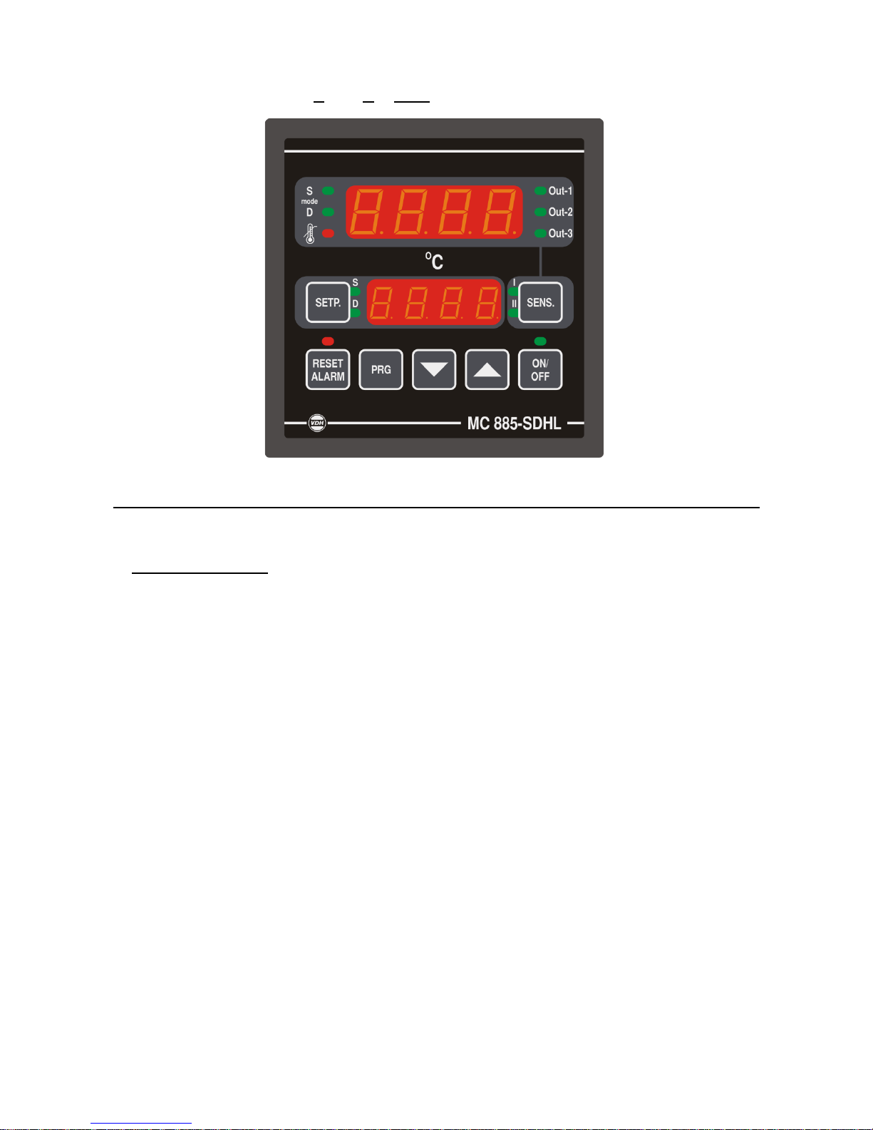
MC 885-SDHL
Spray/Dry High/Low Thermostat
VDH doc: 180146 Version: v1.0 Date: 05-02-2018
Software: 110365_MC 885 SDHL File: Do180146.wpd Range: -50/+300C per 1C
* Working principle
The MC 885 SDHL is a thermostat for controlling >on/off= burners with >high/low= burner control by means of
relay contacts. In addition to this, modulating control is also possible. The thermostat supports 2 mode=s
(mode S and mode D), each having their own setpoint. It is possible to alternate between the mode=s using
a digital input. When applied to a spray booth regulation function, mode S can be used for spraying and
mode D for drying. These modes can be optionally be used in other applications; for example, mode S for
night and mode D for day.
The working principle of the controller is determined by the parameter settings. The controller can control
using 1 or 2 mode=s(/setpoints), with 1 or 2 sensors, where appropriate depending on the current mode (S
or D).
The basic regulation function supports the control functions >burner on=, >burner low= and >burner high= as
shown in the functional flow figure. One of these control functions can be set for each relay. If a burner has
to be controlled with a change-over relay contact >burner high/low=, control function >burner high= can be
used for this on RY2 or RY3.
The measurement and control range are both -50 to 300 C, with a readout per 1 C. The control range can
be reduced using the parameter setting. The top display normally gives the measured room temperature
and the bottom display gives the active setpoint.
In addition to the basic regulation function, the controller also has a minimum and maximum alarm detection
and a maximum limit. The temperature and mode=s at which the alarms and limit should work can be set via
the parameters. The desired action when an alarm or limit is triggered can also be set.
If the controller detects a sensor failure, the regulation function stops, an error message appears in the
display and the alarm relay function becomes active.
The controller also has a configurable analogue output, power-up control delay, buzzer, operate/parameter
passwords and an optional RS485 network connection (for ALFANET or Modbus).
The working principle of these functions is described later in this manual.
Page 2

* Operation
The thermostat is operated using seven buttons on the front:
ON/OFF - switches the controller on and off with LED indicator
SETP. - select, view/change the setpoint value
SENS. - view the values from the individual temperature sensors
PRG - access to the internal parameters
RESET ALARM - reset button for resetting alarms with LED indicator
UP - increase the set value (setpoint/parameters)
DOWN - reduce the set value (setpoint/parameters)
* Switching the controller on and off
The LED above the ON/OFF button shows whether the controller is on or off.
Pressing the ON/OFF button (for at least 1 second) switches the controller on or off. If the thermostat is
switched off, then all the displays are blank and its regulating function is disabled. If the thermostat is
switched on, the room temperature is usually displayed in the top display and the active setpoint in the
bottom display. If a controller delay has been defined after a power interruption then the time remaining is
shown in the lower display (blinking).
* View the individual setpoints
In normal operating mode, the room temperature is shown in the top display (default). If necessary, this can
be changed using parameter P80.
The LED=s next to the SENS. Button indicates which temperature is displayed on the top display: >I= =
Sensor-1 (room temperature), >II= = Sensor-2 (channel temperature), >I= and >II= both on = average of Sensor
1 and Sensor 2. The other temperatures (if present and used) can be displayed by now pressing the SENS
button one or more times. A blinking LED indicates that another temperature is being displayed as normal.
A few seconds after releasing the SENS. button or by pressing the ON/OFF button, the normal room
temperature (P80) will reappear in the display.
* View the individual setpoints
The LED=s next to the SETP. button indicate which setpoint is active. This is shown on the bottom display.
The other setpoint will be displayed (if set using P01) by pressing the SETP. button. A blinking LED
indicates that the inactive setpoint is being displayed.
A few seconds after releasing the SETP. button or by pressing the ON/OFF button, the active setpoint will
reappear in the display and the corresponding LED will be illuminated continuously.
* Changing setpoints
Press (if necessary) the SETP. button until the desired setpoint appears in the display and release the
SETP. button. The setpoint can now be changed by pressing the SETP. button at the same time as the UP
or DOWN buttons. A few seconds after releasing the buttons or by pressing the ON/OFF button, the normal
room temperature (P80) will reappear in the display.
* Mode display
The LED=s mode S and mode D next to the top display indicate the active mode of the controller.
The LED (Max. Limit) indicates whether a maximum limit is active.
The LED=s Out-1, Out-2 and Out-3 show the relays that are active.
* Setting internal parameters
The functioning of the controller can be configured using the internal parameters. By pressing the PRG and
DOWN buttons simultaneously, you can access the internal programming menu. A letter >P= followed by a
number (= parameter number) will appear in the top display. The UP and/or DOWN buttons can be used to
look up the desired parameter.
The value of this parameter is shown in the lower display. This value can be adjusted by pressing the SETP.
button at the same time as the UP or DOWN buttons.
A few seconds after releasing the buttons or by pressing the ON/OFF button, the controller returns to the
normal operating mode.
Page 3
* Parameter table
No. Description
Range
Per Unit Default
01
02
03
04
Dual mode (mode S and mode D) (0 = no, 1 = yes)
(for P01 = no, only mode S)
Channel sensor present (0 = no, 1 = yes)
In mode S, control on
1 = Room temperature
2 = Channel temperature (room temperature if P02 = 0)
3 = Lowest sensor temperature
4 = Highest sensor temperature
5 = Average sensor temperature
In mode D, control on
1 = Room temperature
2 = Duct temperature (room temperature if P02 = 0)
3 = Lowest sensor temperature
4 = Highest sensor temperature
5 = Average sensor temperature
0 1
0 1
1 5
1 5
-
-
-
-
-
-
-
-
0
0
1
1
10
11
Room sensor offset
Channel sensor offset
-15 +15
-15 +15
0.1
0.1
C
C
0.0
0.0
15
16
Minimum adjustable setpoint
Maximum adjustable setpoint
-50 300
-50 300
1
1
C
C
0
+100
20
21
24
25
26
27
28
29
32
33
34
35
36
37
Burner on differential
Burner on offset
Burner low differential
Burner low offset
Burner low only together with >burner on= (0 = no, 1 = yes)
Burner low modulating control (0 = no, 1 = yes)
Burner low duty cycle (for modulating control)
Burner low cycle time (for modulating control)
Burner high differential
Burner high offset
Burner high only together with >burner on= (0 = no, 1 = yes)
Burner high modulating control (0 = no, 1 = yes)
Burner low duty cycle (for modulating control)
Burner low cycle time (for modulating control)
0.1 15
-50 +50
0.1 15
-50 +50
0 1
0 to 1
0 100
5 240
0.1 15
-50 +50
0 1
0 1
0 100
5 240
0.1
0.1
0.1
0.1
-
1
1
0.1
0.1
-
1
1
C
C
C
C
-
%
s
C
C
-
%
s
0.5
+0.5
0.1
-8
1
0
50
60
0.1
-10
1
0
50
60
40
41
42
Relay 1 function
0 = None
1 = Burner on
2 = Burner low
3 = Burner high
4 = Monitor alarm
5 = Control alarm
Relay 2 function
Relay 3 function
0 5
0 5
0 5
1
3
4
45
46
47
48
Analogue output function
0 = None
1 = Room temperature
2 = Channel temperature (room temperature if P02 = 0)
3 = Lowest sensor temperature
4 = Highest sensor temperature
5 = Average sensor temperature
6 = Control temperature
7 = Spraying setpoint
8 = Drying setpoint
9 = Control (= active) setpoint
Analogue output voltage range
0 = 0..5Vdc
1 = 0..10Vdc
Minimum voltage (0V) at temperature
Maximum voltage (P736) at temperature
0 9
0 1
-50 300
-50 300
-
-
1
1
-
-
C
C
0
0
0
100
50 Minimum alarm detection on
0 7 - - 0
Page 4

No. Description
Range
Per Unit Default
51
52
53
54
55
56
0 = None
1 = Room temperature (absolute)
2 = Channel temperature (absolute) (room temperature if P02 = 0)
3 = Lowest sensor temperature
4 = Highest sensor temperature
5 = Average sensor temperature
6 = Control temperature
7 = Control temperature relative to control setpoint
Minimum alarm detection during
0 = Spraying
1 = Drying
2 = Both modes
(always detection for single setpoint)
Minimum alarm temperature
Switch differential for minimum alarm
Time delay for minimum alarm
Action at minimum alarm
(message with code and alarm relay function always appear in display)
0 = None
1 = Disable all burner control
Reset minimum alarm automatically (0 = no, 1 = yes)
0 2
-350 +350
0.1 15
0 99
0 1
0 1
-
1
0.1
1
-
-
-
C
C
min
-
-
2
-50
0.1
0
0
0
60
61
62
63
64
65
66
Maximum alarm detection on
0 = None
1 = Room temperature (absolute)
2 = Channel temperature (absolute) (room temperature if P02 = 0)
3 = Lowest sensor temperature
4 = Highest sensor temperature
5 = Average sensor temperature
6 = Control temperature
7 = Control temperature relative to control setpoint
Maximum alarm detection during
0 = Spraying
1 = Drying
2 = Both modes
(always detection for single setpoint)
Maximum alarm temperature
Switch differential for maximum alarm
Time delay for maximum alarm
Action at minimum alarm
(message with code and alarm relay function always appear in display)
0 = None
1 = Inhibit all burner control
2 = Inhibit burner high
3 = Inhibit burner high, replace with >burner low=
Reset maximum alarm automatically (0 = no, 1 = yes)
0 7
0 2
-350 +350
0.1 15
0 99
0 3
0 1
-
-
1
0.1
1
-
-
-
-
C
C
min
-
-
0
2
+300
0.1
0
1
0
70
71
72
73
74
75
Maximum limit on
0 = None
1 = Room temperature (absolute)
2 = Channel temperature (absolute) (room temperature if P02 = 0)
3 = Lowest sensor temperature
4 = Highest sensor temperature
5 = Average sensor temperature
6 = Control temperature
7 = Control temperature relative to control setpoint
Maximum limit during
0 = Spraying
1 = Drying
2 = Both modes
(always limit for single setpoint)
Maximum temperature limit
Switch differential for maximum limit
Time delay for maximum limit
Action at maximum limit
0 = No limit (same as P70 = 0)
1 = Inhibit all burner control
2 = Inhibit burner high
3 = Inhibit burner high, replace with >burner low=
0 7
0 2
-350 +350
0.1 15
0 99
0 3
-
-
1
0.1
1
-
-
-
C
C
min
-
0
2
+300
0.1
0
1
Page 5

No. Description
Range
Per Unit Default
80
81
82
83
Temperature in top display
1 = Room temperature
2 = Channel temperature (room temperature if P02 = 0)
3 = Lowest sensor temperature
4 = Highest sensor temperature
5 = Average sensor temperature
6 = Control temperature
Controller delay after power interruption
Reset alarm relay after alarm reset (0 = no, 1 = yes)
(without the cause of the alarm being removed)
Buzzer on at alarm (0 = no, 1 = yes
1 6
0 to 99
0 1
0 1
-
1
-
-
-
min
-
-
1
0
0
0
85
86
Operate password (0 = no password)
Parameter password (0 = same as operate password)
0 9999
0 9999
1
1
-
-
0
0
90
91
Network number
Login interval
1 250
1 120
1
1
min
1
5
95
98
99
Software version
Serial number
Production date (year/week)
1.00 ..
99.99
0 9999
00.01 ..
99.52
-
-
-
-
-
-
-
-
-
* Adjusting sensors
The sensors are adjusted using the sensor offset parameters (P111 and P121). If, for example, the
thermostat indicates 2.5C too high for a sensor, then the sensor offset parameter will have to be reduced
by 2.5C.
* Basic regulation function
The basic control is set using parameters P01..04, P20..37 and P40..42:
- A single mode (/setpoint) or 2 modes (/setpoints) (P01)
- Only a room temperature or a channel temperature sensor (P02)
- Control temperature for mode S (and for single mode) (P03)
- Control temperature for mode D (P04)
The basic control supports 3 adjustment functions: >Burner on=, >burner low= and >burner high=. This is shown
in the functional flow figure. The >active setpoint= is determined by the active mode (mode S or D). The
>active control temperature= is the control temperature for the active mode as set using parameters P03 and
P04.
The control settings for these control functions are set using parameters P20..37.
If modulating control is set for a control function, the control function modulating with an adjustable (fixed)
duty cycle and an adjustable (fixed) cycle time will be indicated in the situations shown in the figure >on=.
This modulating control can, for example, be used for a capacity/power setting.
A control function can be selected for each individual relay using parameters P40..42.
Page 6

* Functional flow
Page 7

* Alarms
In addition to the basic control, the controller also has a minimum and maximum alarm detection.
At what temperature (P50/P60), in which mode (P51/P61), at which temperature (P52/P62), with which
differential (P53/P63) and time delay (P54/P64) the alarms should be triggered can be set using
parameters.
If an alarm occurs, the LED above the RESET ALARM button lights up. The alarm report is shown in the
upper display.
Pressing the RESET ALARM button allows the alarms to be reset one by one. Once all the alarms are
reset, the LED above the RESET ALARM button goes out.
What actions that should occur for the various alarms can be set using parameters (P55/P65).
The following alarm notifications can appear in the upper display:
Lo - Minimum alarm
Hi - Maximum alarm
E1 - Sensor-1 defect
E2 - Sensor-2 defect
Solution E1, E2:
- Check that the sensor is connected properly.
- Check sensor (100Ω at 0C).
- Replace sensor
An alarm condition is removed when the cause is eliminated and the alarm has been reset using the RESET
ALARM button.
Automatic reset can be set for the minimum and maximum alarm with parameters (P56/P66). The relevant
alarm condition will be automatically removed when the cause of the error has been removed. An alarm
reset using the RESET ALARM button will then be unnecessary.
After all of the alarms have been rest, the temperature will be displayed again in the upper display,
alternated with any alarm notifications for which the cause has not yet been removed. If the temperature
cannot be measured (out of range), then the display will instead show L for a short-circuited sensor or H for
an open sensor circuit.
* Maximum limit
The basic control can be overruled by the maximum limit, if set using parameters P70..P75.
At which temperature (P70), in which mode (P71), with which differential (P73) and time delay (P74) the
maximum limit should come into effect can be set using parameters. The desired overruling action can be
set using parameter P75.
When the maximum limit is active, this will be indicated by the LED (Max. Limit).
* Controller delay after power failure
The controller supports a delayed regulation function after a power failure. If set (P08), no controller
functions will be performed within the delayed regulation period after the controller is powered up again.
The sensor values, setpoints and parameters can be viewed and modified, though. During the delayed
regulation period, the remaining time is shown blinking in the lower display.
If necessary, the control delay can be cleared by switching the controller off and on again with the ON/OFF
button.
* Passwords
If an operator password has been set (P85), a four-digit password will first need to be given for operations
that affect the regulation function. The text ACode@ appears in the upper display, and A- - - -A in the lower
display.
The UP and DOWN buttons can be used to enter the first digit. The ON/OFF button can then be used to
move on to the next digit. After all 4 digits have been entered correctly in this fashion, the operator action
can be performed. The password remains in force until no buttons have been pressed 2 minutes. After that,
the password has to be entered once more before the controller can be operated again.
There is a parameter password for viewing and changing the parameters. If this has been set (P86), this
password must be entered in the same way as the operator password. The parameter password also
enables the operator actions.
Page 8

* Technical data
Type : MC885 SDHL Sprayer/Dryer High/Low Thermostat
Range : -50/+300C, readout per 1C
Operation : Via push buttons on the front
Front : Polycarbonate IP65
Dimensions : 96 x 96 x 140 mm (H x W x D)
Panel cutaway : 90 x 90 mm (H x W)
Accuracy : 0,5% of the range
Power supply: 100 B 260Vac 47-440Hz of 120 B 370 Vdc, power 5 watts or otherwise: see product
sticker
Relay: RY1 : Function adjustable (P40), default Burner on SPST C-NO contact
RY2 : Function adjustable (P40), default Burner high SPDT C-NO-NC contact
RY3 : Function adjustable (P40), default Burner on SPDT C-NO-NC contact
For all relays: maximum 8A at 250 Vac with Cos phi=1.0
6A at 250 Vac with Cos phi=0.4
or 5A at 30 Vdc
Temp. sensor : Pt100-1 Room temperature sensor a,b,c; 3-wire system
Pt100-2 Room temperature sensor (option) a,b,c; 3-wire system
Digital input : Contact input function spray (open)/dry (closed) Potential free connection
Analogue output : 0-10 Vdc or 0-5 Vdc (P46) measurement or setpoint value output max. 1mA
Choice via parameter P45:
- Room temperature
- Channel temperature (if present)
- Lowest sensor temperature
- Highest sensor temperature
- Average sensor temperature
- Control temperature (active sensor)
- Spray setpoint
- Dry setpoint
- Control (active) setpoint
Communication : Optional RS485 for ALFANET or Modbus (Line-A, Line-B and GND) 2 x twisted pair
shielded connections – see wiring diagram
Buzzer : On the processor PCB, used for alarms (dependent on parameter P82)
Displays : Upper: 4-digit 7-segment display, 13 mm (red) for temperature readout
Lower: 4-digit 7-segment display, 10 mm (red) for setpoint readout
LEDs status : LED mode S mode S active
LED mode D mode S active
LED Max Limit Maximum limit active
LED Out-1 RY1 energised
LED Out-2 RY2 energised
LED Out-3 RY3 energised
Page 9

* Wiring diagram
Page 10

* Dimensions
* Address
VDH Products BV Tel.: +31 (0)50 - 30 28 900
Produktieweg 1 Fax: +31 (0)50 - 30 28 980
9301 ZS Roden Email: info@vdhproducts.nl
The Netherlands Internet: www.vdhproducts.nl
 Loading...