

Page 1
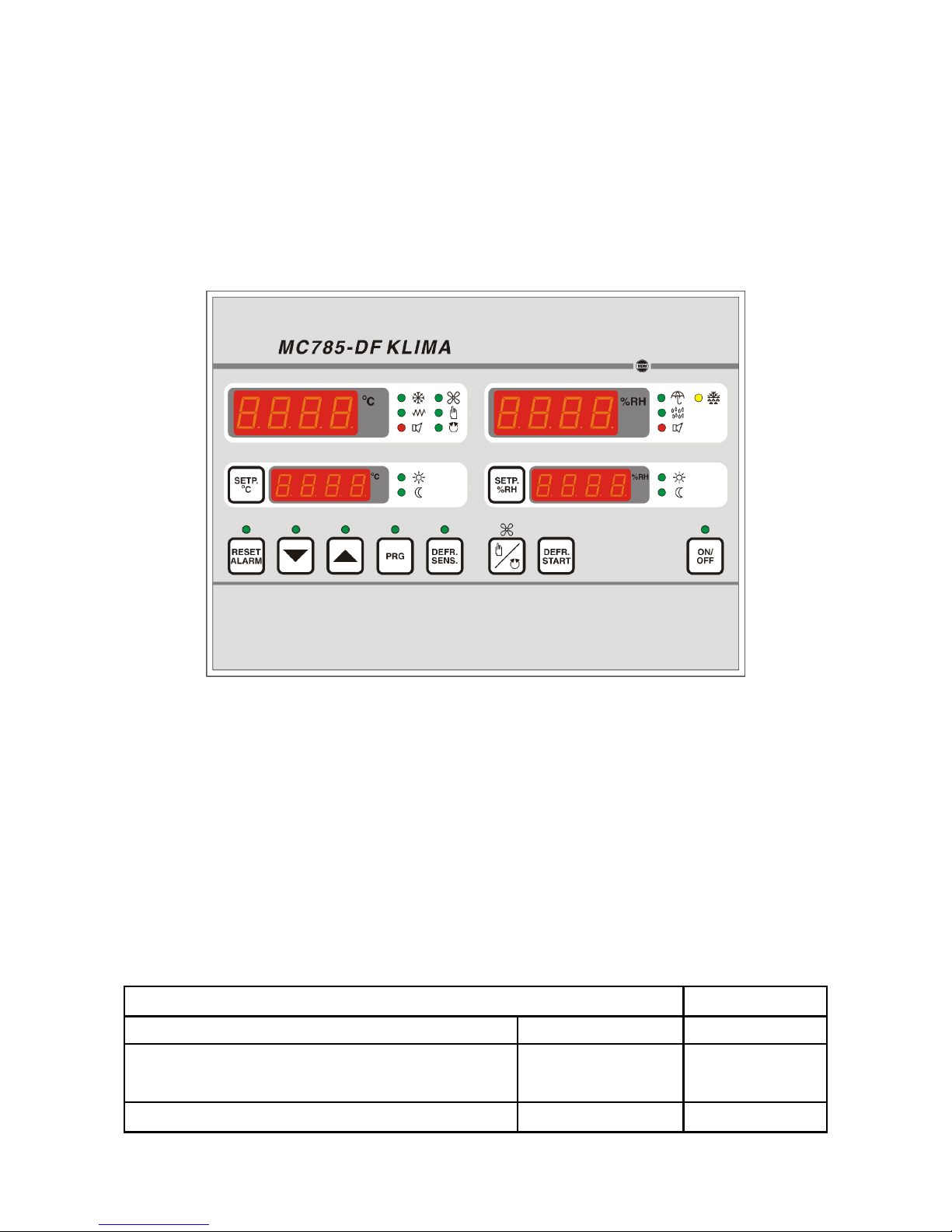
MC 785-DF KLIMA
ALFANET implementation
Operating Manual
(Wall and panel mounting)
Description : MC 785-DF KLIMA ALFANET (RS485) Thermo/hygrostat Doc.nr.: 010346
Type: MANUAL Number of pages: 20 Version: V1.4
File: Do010346 MC785-DF KLIMA Alfanet v14 EN.wpd
Software: 010187 MC 785 DF Kli Alfanet
Version: V1.03
By: BJB Date: 15-02-2018
VDH Products BV - Roden - Holland Signed: File: Doc'01
Page 2

Operating manual Document nr. : 010346 Version : V1.4
MC 785-DF KLIMA ALFANET Client : General Page : 2 of 20
Table of contents
1. Technical specifications. ........................................................... 3
1.1 Controller General .......................................................... 3
1.2 LMS Relay module .......................................................... 4
1.3 LMS 4x Pt100 module ....................................................... 4
1.4 LMS Analog-out module ...................................................... 4
1.5 LMS Supply module ......................................................... 4
2. Functional specifications. .......................................................... 5
3. Control. ........................................................................ 6
3.1 Readout (lowest) defrost temperature and seperate sensors. .......................... 6
3.2 Changing the temperature setpoint. ............................................. 6
3.3 Changing of the RH setpoint. .................................................. 6
3.4 Resetting the alarm. ......................................................... 6
3.5 Day/night input. ............................................................ 6
3.6 Manual start of defrost. ....................................................... 7
3.7 Operation of fan control. ...................................................... 7
3.8 Readout output percentages of the analog outputs CH-1 untill CH-4. .................... 7
4. Programming internal settings. ...................................................... 8
4.1 Parameter table ............................................................ 8
5. Operation of the relay outputs. ......................................................13
5.1 Operation of the cooling and heating. ............................................13
5.2 Operation of the humidification and dehumidification ................................13
5.3 Operation of defrost. ........................................................13
6. Sensor calibration. ...............................................................14
7. Alarms. ........................................................................14
8. Front view. .....................................................................15
9. Connection diagram. ..............................................................16
10. Dimensions. ....................................................................19
The information in this document is assumed to be accurate. However VDH Products B.V. accepts no liability for
eventual m istakes or errors and has the right to change this docum ent without notice.
Page 3
Operating manual Document nr. : 010346 Version : V1.4
MC 785-DF KLIMA ALFANET Client : General Page : 3 of 20
1. Technical specifications.
1.1 Controller General
Type : MC 785-DF KLIMA ALFANET
Wall mounting:
Housing : Grey plastic
Material : Polystyrol 454h KG 2 natur BASF
Dimensions : 213 x 180 x 85mm (whd)
Front : Polycarbonat
Panel mounting:
Housing : Steel plate panel
Material : Steel in silver grey
Dimensions : 217 x 155 x 85mm (whd)
Panel cutout : min. 208 x 146mm (wh)
Front : Polycarbonat
Temperature range : -40/+50EC per 0,1EC
Humidity range : 0/+100% RH per 0,1% RH
Supply : 230 Vac; 50/60 Hz (-10/+5%).
Used power : 9 VA
Operation temperature : Max. 40EC
Controller Front
Display : 4-digit digital display for measured temperature
4-digit digital display for temperature setpoint
4-digit digital display for measured RH
4-digit digital display for RH setpoint
LED's : COOL = LED Relay cooling active
HEAT = LED Relay heating active
DEHUM = LeD Relay dehumidification active
HUM = LED Relay humidification active
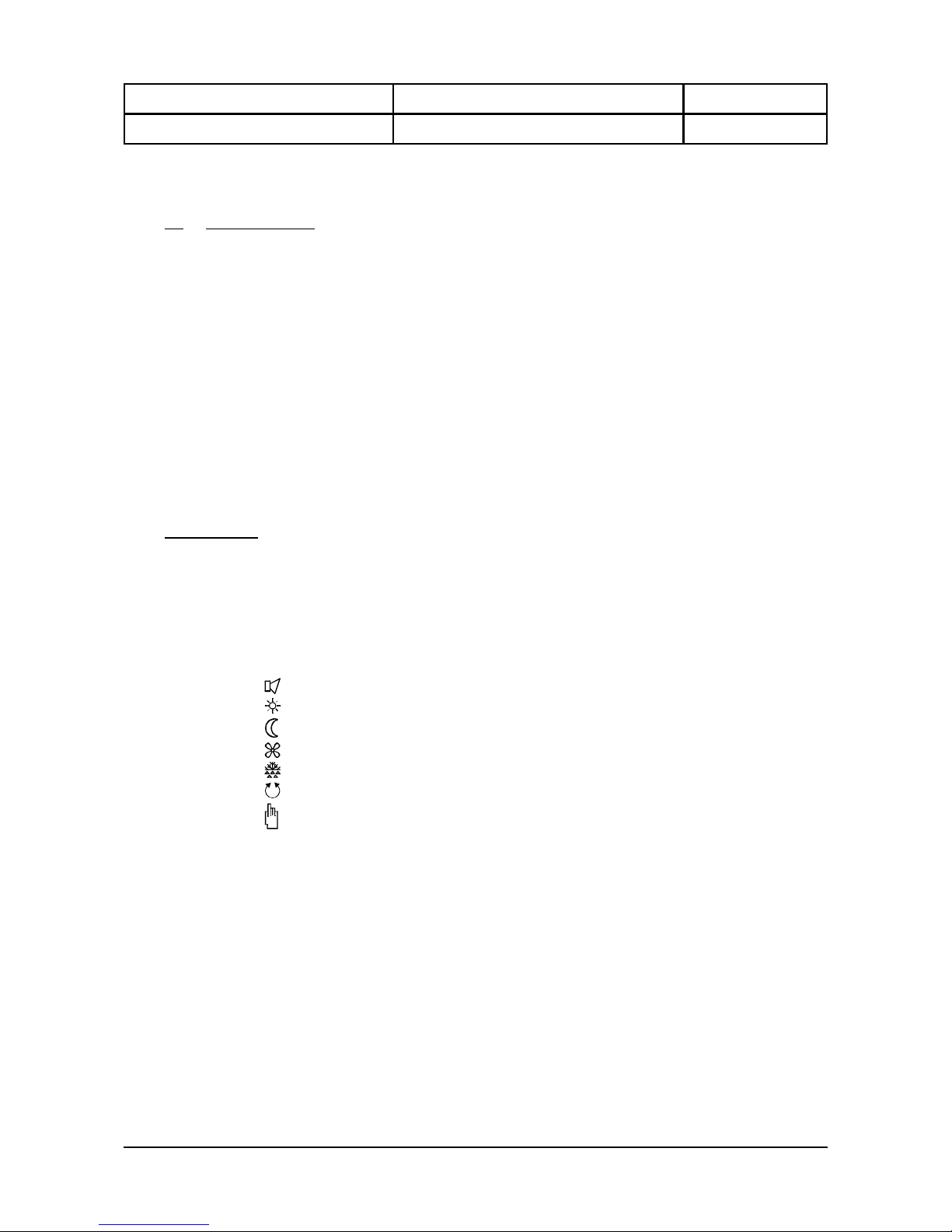
= LED Alarm active (flashing)
= LED Day mode active
= LED Night mode active
= LED Fan active
= LED Defrost active
= LED Fan in auto mode
= LED Fan in manual mode (hand)
Keys : ON/OFF = On/Off key controller
SET = Setpoint push button
> = Up key
? = Down key
PRG = Program key
RESET ALARM = Alarm reset key
FAN = Fan auto/manual key
DEFR START = Start defrost key
DEFR SENS = Read-out defrost sensor key
Page 4

Operating manual Document nr. : 010346 Version : V1.4
MC 785-DF KLIMA ALFANET Client : General Page : 4 of 20
Controller in- and outputs
Sensors : Temperature sensor (Pt-100, 3-wire to DIN/IEC 751)
Defrost sensor (Pt-100, 3-wire to DIN/IEC 751)
RH sensor (0/+1 Vdc = 0/+100% RH)
Digital input : Day/night input (potential free input contact)
Analog output : Out-1=CH-1; 0/+10Vdc, (Rbmin 10Kohm, programmable)
Relay outputs : RY1 Extra relay (C/NO/NC, 250Vac/10A not inductive)
Following relays have a central common;
RY2 Dehumidify (NO, 250Vac/10A not inductive)
RY3 Humidify (NO, 250Vac/10A not inductive)
RY4 Heating (NO, 250Vac/10A not inductive)
RY5 Cooling (NO/NC, 250Vac/10A not inductive)
Please note ! Relay functions are programmable. These are the default settings.
Communcation : I²C network
1
(2-wire shielded; 0V,SDA,SCL)
RS485 network
2
according to NORM: ANSI/TIA/EIA-485-A-98
(2x Twisted-pair shielded, min. 0,5mm2; GND,A,B)
1.2 LMS Relay module
Supply : 12Vdc / 1,2VA (from separate supply)
Communication : I2C network
1
(2-wire shielded 0V,SDA,SCL)
Relay outputs : RY1 Defrost (C/NO/NC, 250Vac/10A not inductive)
RY2 Fan (C/NO, 250Vac/10A not inductive)
RY3 Spare (C/NO, 250Vac/10A not inductive)
RY4 Spare (C/NO, 250Vac/10A not inductive)
Please note ! Relay functions are programmable. These are the default settings.
1.3 LMS 4x Pt100 module
Supply : 12Vdc / 1,2VA
Communication : I2C network
1
(2-wire shielded 0V,SDA,SCL)
Sensors : Pt100-1 (3-wire according to DIN/IEC 751, programmable)
Pt100-2 (3-wire according to DIN/IEC 751, programmable)
Pt100-3 (3-wire according to DIN/IEC 751, programmable)
Pt100-4 (3-wire according to DIN/IEC 751, programmable)
1.4 LMS Analog-out module
Supply : 12Vdc / 1,1VA (from separate supply)
Communication : I2C network
1
(2-wire shielded 0V,SDA,SCL)
Analog outputs : Out-1=CH-2; 0/+10Vdc (Rbmin 10Kohm, programmable)
Out-2=CH-3; 0/+10Vdc (Rbmin 10Kohm, programmable)
Out-3=CH-4; 0/+10Vdc (Rbmin 10Kohm, programmable)
Out-4=CH-5; 0/+10Vdc (Rbmin 10Kohm, highest output percentage
Please note ! Analog functions are programmable. of CH-1 and CH-2)
1.5 LMS Supply module
Supply : 230Vac 50/60Hz, 7VA
Outputs : 3x 12Vdc
1I2
C cable: 2-wire shielded cable connect SDA and SCL as wires and connect shield to Gnd (0V).
Maximum length I2C cable is 5 meter.
2
RS485 cable: 2xTwisted-pair with in pair-1 line A and B, in pair-2 2xGnd (or 1 wire with Gnd) and shield only
at one side to earth (PE). Make no side branches.
Maximum total length of RS485 cable is 1 KM.
Terminate the cable at both ends by connecting a resistor of 250 Ohm between line A and B.
Page 5

Operating manual Document nr. : 010346 Version : V1.4
MC 785-DF KLIMA ALFANET Client : General Page : 5 of 20
2. Functional specifications.
The MC785-DF KLIMA has the following control functions:
• cooling
• heating
• dehumidfying
• humidifying
Further more the controller has an alarm relay, which is activeted when the alarm levels are exceeded or a
sensor is broken.
Four addition temperature sensors can be connected to the Controller thru the LMS 4x Pt100 Module.
These sensors can assigned as control-, defrost- or productsensor.
• In case that extra sensors are assigned as control sensor to the controller, it regulates the temperature
with the average temperature of these sensors.
• In case that extra sensor are assigned as defrost sensor to the controller, it uses the lowest
temperature of these defrost sensors to defrost the controller.
• In case that extra sensors are assigned as product sensor to the controller, it uses them only for
readout.
A selection between four different modes of defrosts can be made:
• no defrost,
• natural defrost
• el ectric defrost
• hotgas defrost
The controller has five analog outputs available with a range of 0/+10Vdc (CH-1 to CH-5).
Whereby CH-1 is connected direct to the controller and CH-2 untill CH-5 is connected at the LMS analog out
module (out-1 untill out-4). From which four outputs (CH-1 to CH-4) are programmable as:
• measuring signal
• setpoint signal
• P(I) control for cooling
• P(I) control for heating
• P(I) control for humifying
• P(I) control for dehumifying
And one output CH-5 has the function of the highest output percentage of CH-1 (Out-1 at the MC785-DF
KLIMA) and CH-2 (Out-1 at the LMS Anaolg-out module).
The controller has a digital input contact which is used as day/night input.
The selection of the above-mentioned settings is done thru the Internal Parameters.
The controller can also be connected to the ALFANET, thru the RS485-network connection, to view or set the
controller.
Page 6

Operating manual Document nr. : 010346 Version : V1.4
MC 785-DF KLIMA ALFANET Client : General Page : 6 of 20
3. Control.
During normal operation the upper displays show the (average) control temperature and measured rel. humidity
and the lower displays show the temperature setpoint and the RH setpoint.
3.1 Readout (lowest) defrost temperature and seperate sensors.
Press the DEFR.SENS key to readout the lowest defrost temperature sensor on the temperature display.
The setpoint display shows now ‘dEfr’ to indicate that the lowest defrost temperature is being shown.
By pressing the DEFR.SENS key repeatedly the separate sensors will be shown in the temperature
display according to the sensor configuration. The setpoint display shows which sensor is being shown:
dEfr : lowest defrost sensor temperature
rEG0 : control sensor connected to the controller itself
dEf0 : defrost sensor connected to the controller itself.
LmS1 : LMS sensor-1 connected at the LMS Pt100 module.
LmS2 : LMS sensor-2 connected at the LMS Pt100 module.
LmS3 : LMS sensor-3 connected at the LMS Pt100 module.
LmS4 : LMS sensor-4 connected at the LMS Pt100 module.
If for 10 seconds no key is pressed, than the control will return to it’s normal operation and shows the
(average) control temperature and it’s setpoint again.
3.2 Changing the temperature setpoint.
Push the SET key next to the temperature setpoint display. The setpoint starts flashing. The setpoint can
be changed with the UP and DOWN key. By pushing the SET key once again, the setpoint shows
contineously in the display.
Is the MC 785-DF KLIMA in the day mode (DAY LED on) and should the night setpoint be watched or
changed, push the UP or DOWN key and next on the SET key. The LED of the other mode flashes, the
setpoint appears flashing in the display. Changing of the setpoint again wuth the UP or DOWN keys and
acknoledge with the SET key.
In the same way the day setpoint can be watched or changed if the MC 785-DF KLIMA is in the night
mode.
3.3 Changing of the RH setpoint.
Push the SET key next to the RH setpoint display. The setpoint starts flashing and can be changed with
the UP or DOWN keys. By pressing the SET key again the setpoint appears contineously in the display.
If the instrument is in the day mode (DAG LED on) and the night setpoint needs to watched or changed,
push the UP or DOWN key and next push the SET key. The LED of the other mode flashes, the setpoint
appears flashing in the display. Changing of this setpoint again with the UP or DOWN keys and
acknoledge with the SET key.
In the same way the day setpoint can be watched or changed if the MC 785 KLIMA is in the night mode.
3.4 Resetting the alarm.
As soon as an alarm situation occurs and a failre message appears in the temperature display can, by
pushing the RESET ALARM key, the alarm be reset.
The error meaasage remains in the display, till the cause of the failure is solved.
3.5 Day/night input.
If the day/night input is closed, the MC 785-DF KLIMA switches from day to night mode. The night LED
light. If the input is opened, the controller switches back to the day mode.
Page 7

Operating manual Document nr. : 010346 Version : V1.4
MC 785-DF KLIMA ALFANET Client : General Page : 7 of 20
3.6 Manual start of defrost.
By pressing the DEFR key, the defrost can be started manually, and therefor independent of the defrost
timer. The defrost release temperature is not taken into account. The defrost will always start.
3.7 Operation of fan control.
With the FAN key can be switched between the manual and automatic fan mode. In the manual mode
the fan will run contineously, in the auto mode the fan will only run during cooling or heating, including
the fan off delay time. During electric defrost the fan will always stop.
3.8 Readout output percentages of the analog outputs CH-1 untill CH-4.
Press the PRG key (and hold it) and than press the DEFR.SENS key to readout the output percentage of
analog output CH-1. The output percentage will appear in the temperature display while the setpoint
display shows ‘AnA1' to indicate this readout of CH-1.
By pressing the DEFR.SENS key (without the PRG key) the next output percentages will appear in the
temperature display while the setpoint display shows which percentage is shown:
Ana1 : Output percentage of analog output CH-1
Ana2 : Output percentage of analog output CH-2
Ana3 : Output percentage of analog output CH-3
Ana4 : Output percentage of analog output CH-4
If for 10 seconds no key is pressed, than the control will return to it’s normal operation and shows the
(average) control temperature and it’s setpoint again.
Page 8

Operating manual Document nr. : 010346 Version : V1.4
MC 785-DF KLIMA ALFANET Client : General Page : 8 of 20
4. Programming internal settings.
By pressing the PRG and RESET ALARM ket at the same time for more than 5 seconds, the Interne Parameter
menu is entered. In the display appears a P with a number behind it. With the UP or DOWN key the required
parameter is selected.
If the required parameter is reached, can by pushing the PRG key, the value of the parameter be watched. By
simulteaneously pressing the PRG with the UP or DOWN key, the value can be adjusted. After releasingf the
keys, the parameter number appears again in the display.
If during 30 seconds no key is touched, the display turn back to the normal operation mode.
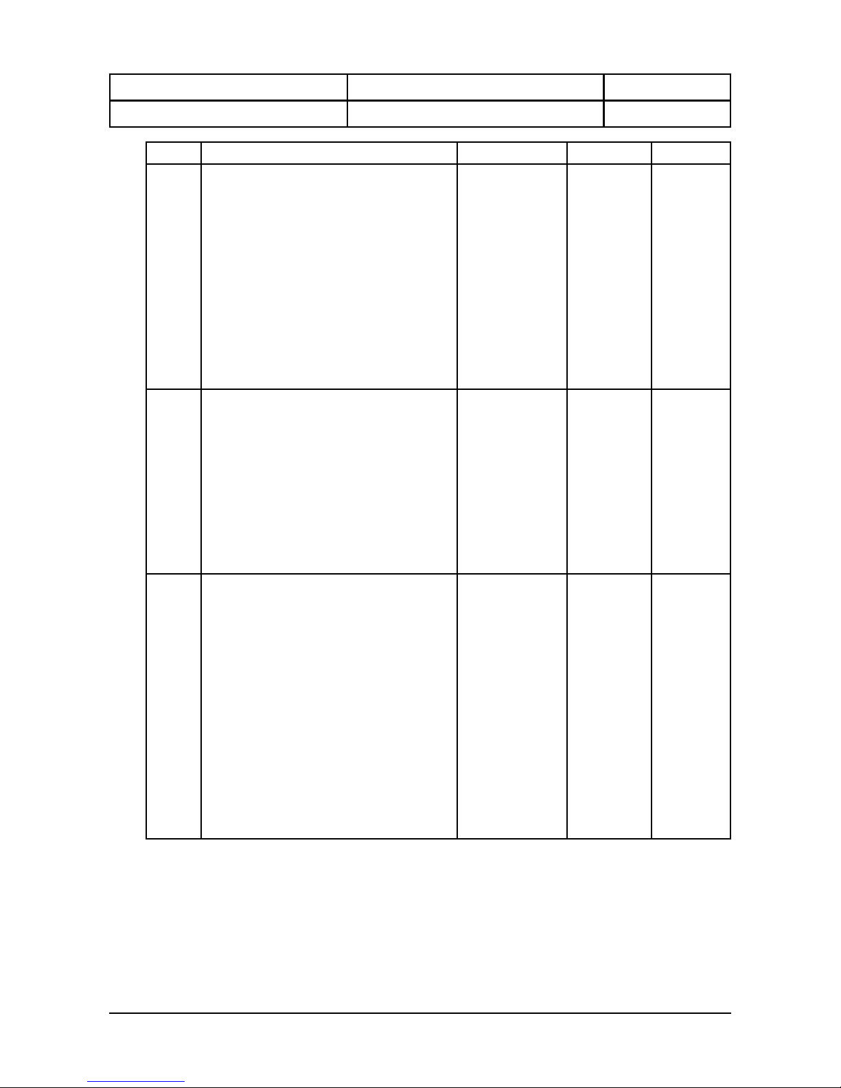
4.1 Parameter table.
Nr Description Range Unit Default
P 01
P 02
P 03
P 04
P 05
P 06
P 07
P 08
Differential cooling
Offset cooling
Differential heating
Offset heating
Differential dehumidifying
Offset dehumidifying
Differential humidifying
Offset humidifying
0.1..15
-15..+15
0.1..15
-15..+15
0.1..15
-15..+15
0.1..15
-15..+15
EC
EC
EC
EC
% RH
% RH
% RH
% RH
0.5
0.0
0.5
0.0
1.0
0.0
1.0
0.0
P 10
P 11
P 12
P 15
Offset temperature sensor
Offset defrost sensor
Offset RH sensor
Defrost sensor present
-10/+10
-10/+10
-15/+15
0 = no, 1 = yes
EC
EC
% RH
-
0.0
0.0
0.0
1
P 20
P 21
P 22
Function extra relay (see also P154)
0 = watch alarm
1 = control alarm
2 = cooling
3 = heating
4 = dehumidifying
5 = humidifying
6 = watch alarm not resetable
7 = control alarm not resetable
Differential extra relay
Offset extra relay
0..7
0.1..15
-15..+15
-
-
-
0
0.5
0.0
P 30
P 31
P 32
P 33
P 34
P 35
P 36
Minim um setting temperature setpoint
Maximum setting temperature setpoint
Readout above -10EC per 1EC
Readout below -10EC per 1EC
Minim um setting RH setpoint
Maximum setting RH setpoint
Read out per 1% RH
-40..+50
-40..+50
0 = no, 1 = yes
0 = no, 1 = yes
0..100
0..100
0 = no, 1 = yes
EC
EC
-
-
% RH
% RH
-
-40.0
+50.0
0
1
0
100
0
Page 9
Operating manual Document nr. : 010346 Version : V1.4
MC 785-DF KLIMA ALFANET Client : General Page : 9 of 20
Nr Description Range Unit Default
P 40
P 41
P 42
P 43
P 44
P 45
P 46
P 47
P 48
Type temperature alarm
0 = No alarm
1 = Absolute alarm
2 = Relative to setpoint
Minim um alarm temperature
Maximum alarm temperature
Minim um alarm delay
Maximum alarm delay
Temperature control-off at minimum alarm
Temperature control-off at maximum alarm
Humidity control-off at m in. temp. alarm
Humidity control-off at m ax. temp. alarm
0..2
-40..+50
-40..+50
0..99
0..99
0 = no, 1 = yes
0 = no, 1 = yes
0 = no, 1 = yes
0 = no, 1 = yes
-
EC
EC
minutes
minutes
-
-
-
-
1
-40.0
+50.0
0
0
0
0
0
0
P 50
P 51
P 52
P 53
P 54
P 55
P 56
Type RH alarm
0 = No alarm
1 = Absolute alarm
2 = Relative to setpoint
Minim um RH alarm
Maximum RH alarm
Minim um alarm delay
Maximum alarm delay
RH control-off at minimum alarm
RH control-off at maximum alarm
0..2
-100..100
0..100
0..99
0..99
0 = no, 1 = yes
0 = no, 1 = yes
-
% RH
% RH
minutes
minutes
-
-
1
0
100
0
0
0
0
P 60
P 61
P 62
P 63
P 64
P 65
P 66
P 67
Function analog CH-1
0 = Measured temperature
1 = Measured RH
2 = Temperature setpoint
3 = RH setpoint
4 = P(I) cooling
5 = P(I) heating
6 = P(I) dehumidifying
7 = P(I) humidifying
0 V output at
10 V output at
Proportional range
Offset proportional range
Interval value (999 give only P)
As puls/pauze
Puls/pause cycle time
0..7
-100..+100
-100..+100
0.1..15
-15..+15
1..999
0 = no, 1 = yes
5..240
-
-
-
-
-
minutes
-
seconds
0
-40.0
+50.0
1.0
0.0
999
0
20
Page 10

Operating manual Document nr. : 010346 Version : V1.4
MC 785-DF KLIMA ALFANET Client : General Page : 10 of 20
Nr Description Range Unit Default
P 70
P 71
P 72
P 73
P 74
P 75
P 76
P 77
Function analog CH-2
0 = Measured temperature
1 = Measured RH
2 = Temperature setpoint
3 = RH setpoint
4 = P(I) cooling
5 = P(I) heating
6 = P(I) dehumidifying
7 = P(I) humidifying
0 V output at
10 V output at
Proportional range
Offset proportional range
Interval value (999 give only P)
As puls/pauze
Pulse/pauze cycle time
0..7
-100..+100
-100..+100
0.1..15
-15..+15
1..999
0 = no, 1 = yes
5..240
-
-
-
-
-
minutes
-
seconds
0
-40.0
+50.0
1.0
0.0
999
0
20
P 80
P 81
P 82
P 83
P 84
P 85
Function analog CH-3
0 = Measured temperature
1 = Measured RH
2 = Temperature setpoint
3 = RH setpoint
4 = P(I) cooling
5 = P(I) heating
6 = P(I) dehumidifying
7 = P(I) humidifying
0 V output at
10 V output at
Proportional range
Offset proportional range
Interval value (999 give only P)
0..7
-100..+100
-100..+100
0.1..15
-15..+15
1..999
-
-
-
-
-
minutes
0
-40.0
+50.0
1.0
0.0
999
P 90
P 91
P 92
P 93
P 94
P 95
Function analog CH-4
0 = Measured temperature
1 = Measured RH
2 = Temperature setpoint
3 = RH setpoint
4 = P(I) cooling
5 = P(I) heating
6 = P(I) dehumidifying
7 = P(I) humidifying
0 V output at
10 V output at
Proportional range
Offset prop. range
Interval value (999 give only P)
0..7
-100..+100
-100..+100
0.1..15
-15..+15
1..999
-
-
-
-
-
minutes
0
-40.0
+50.0
1.0
0.0
999
P 100
P 101
P 102
P 103
P 104
Start delay cooling
Stop delay cooling
Parameter 100/101 in seconds or minutes
Minim um on-tim e cooling
Minim um off-time cooling
0..99
0..99
0 = sec, 1 = min
0..99
0..99
-
-
-
minutes
minutes
0
0
0
0
0
Page 11

Operating manual Document nr. : 010346 Version : V1.4
MC 785-DF KLIMA ALFANET Client : General Page : 11 of 20
Nr Description Range Unit Default
P 110
P 111
P 112
P 113
Switch off delay fan
Switch on temperature fan after defrost
Switch on delay fan after defrost
Drainage time
0..99
-40..+50
0..99
0..99
minutes
EC
minutes
minutes
0
2.0
0
0
P 120
P 121
P 122
P 123
P 124
P 125
P 126
P 127
P 128
Defrost mode
0 = no defrost
1 = natural defrost
2 = elektric defrost
3 = hot gas defrost
Defrost interval
Maximum defrost time
End of defrost temperature
Defrost release temperature
If the evaporator temperature is higher
than the release temperature the
defrost is not started.
Defrost relay during natural defrost active
Defrost based on compressor run tim e
Display fixed during defrost
Maximum tim e display fixed
0..3
1..99
1..99
-10..+30
-40..+50
0 = no, 1 = yes
0 = no, 1 = yes
0 = no, 1 = yes
1..99
-
hours
minutes
EC
EC
-
-
-
minutes
0
12
30
5.0
2.0
0
0
0
15
P 130
P 131
P 132
P 133
P 134
P 135
P 136
P 137
If cooling on then
0 = nothing off
1 = humidify off
2 = dehumidify off
If heating on then
0 = nothing off
1 = humidify off
2 = dehumidify off
If humidify on then
0 = nothing off
1 = cooling off
2 = heating off
If dehumidifying is active then
0 = notthing
1 = cooling off
2 = heating off
Dehumidifying by
0 = nothing
1 = cooling contact
2 = heating contact
During humidifying fan on
During dehumidifying fan on
During heating fan on
0..2
0..2
0..2
0..2
0..2
0 = no, 1 = yes
0 = no, 1 = yes
0 = no, 1 = yes
-
-
-
-
-
-
-
-
0
0
0
0
0
0
0
1
P 140 Day/night function
0 = day/night function off
1 = day/night function on
2 = day/night function on and
humidity control off
0..2 - 0
Page 12

Operating manual Document nr. : 010346 Version : V1.4
MC 785-DF KLIMA ALFANET Client : General Page : 12 of 20
Nr Description Range Unit Default
P 145
P 146
P 147
P 148
Fan switch-on threshold P(I) cooling
Fan switch-on threshold P(I) heating
Fan switch-on threshold P(I) dehumidifying
Fan switch-on threshold P(I) humidifying
*) The fan becomes active as the
output percentage of a analog
output with this function is above
the treshold.
0..100
0..100
0..100
0..100
%
%
%
%
50
50
50
50
P 150
P 151
P 152
P 153
P 154
P 155
P 156
Relay cooling
0 = no
1 = RY1 (MC 785-DF KLIMA)
2 = RY2 (MC 785-DF KLIMA)
3 = RY3 (MC 785-DF KLIMA)
4 = RY4 (MC 785-DF KLIMA)
5 = RY5 (MC 785-DF KLIMA)
6 = RY1 (LMS relay module)
7 = RY2 (LMS relay module)
8 = RY3 (LMS relay module)
9 = RY4 (LMS relay module)
Relay heating
Relay humidify
Relay dehumidify
Relay extra function (see also P20)
Relay defrost
Relay fan
0..9
0..9
0..9
0..9
0..9
0..9
0..9
-
-
-
-
-
-
-
5
4
3
2
1
6
7
P 160
P 161
Network number
Log interval
1..250
0..120
-
minutes
1
5
P 170
P 171
P 172
P 173
Function LMS Pt100-1
0 = none
1 = extra control sensor
2 = extra defrost sensor
3 = product sensor
Function LMS Pt100-2
Function LMS Pt100-3
Function LMS Pt100-4
0..3
0..3
0..3
0..3
-
-
-
-
0
0
0
0
P180
P181
P182
P183
Offset LMS Pt100-1
Offset LMS Pt100-2
Offset LMS Pt100-3
Offset LMS Pt100-4
-15..+15
-15..+15
-15..+15
-15..+15
EC
EC
EC
EC
0.0
0.0
0.0
0.0
P 190
P 191
P 192
Software version (read only)
Serial number (read only)
Production date (read only)
-
-
-
-
-
year/wk
-
-
Page 13

Operating manual Document nr. : 010346 Version : V1.4
MC 785-DF KLIMA ALFANET Client : General Page : 13 of 20
5. Operation of the relay outputs.
5.1 Operation of the cooling and heating.
The cooling (default RY5) switches if the temperature is higher than setpoint + offset cooling +
differential cooling and switches off if the temperature is lower than setpoint + offset cooling.
The heating (default RY4) switches if the temperature is lower than setpoint + offset heating -
differential heating and switches off id the temperature is higher than setpoint + offset heating.
5.2 Operation of the humidification and dehumidification
The dehumidification (default RY2) switches on if the RH is higher than setpoint + offset
dehumidification + differential dehumidification and switches off if the RH is lower than setpoint +
offset dehumidification.
The humidification (default RY3) switches on if the RH is lower than the setpoint + offset
humidification - differential humidification and switches off if the RH is lower than setpoint + offset
humidification.
5.3 Operation of defrost.
There are four different methods for the defrost.
1. No defrost.
2. Natural defrost.
Before the defrost is started, a check is done to see if the temperature of the defrost sensor is
lower than the defrost release temperature (P 94). If this is not the case, the defrosted is skipped.
If the defrost starts, the cooling is switched off and the defrost relay is on. The fan will run
continuously during the defrost. The defrost is stopped if the end-of-defrost temperature is
reached (P 93), with a limit on the maximum defrost time (P 92).
3/4. Electric/hot-gas defrost.
Before the defrost is started, a check is done to see if the temperature of the defrost sensor is
lower than the defrost release temperature (P 94). If this is not the case, the defrosted is skipped.
If the defrost starts, the cooling is switched off, the fan stops and the defrost relay is switched on.
The defrost is stopped if the end-of-defrost temperature is reached (P 93), with a limit on the
maximum defrost time (P 92).
After defrost the fan will start when the defrost-sensor reaches a temperature lower than the fan
release temperature (P 81).
Page 14

Operating manual Document nr. : 010346 Version : V1.4
MC 785-DF KLIMA ALFANET Client : General Page : 14 of 20
6. Sensor calibration.
With parameters P10, P11, P12, P180, P181, P182 and P183 the temperature sensors and RH sensor can be
calibrated.
Indicates the temperature sensor e.g. 0,2°C too much, the according temperature offset should be set 0,2°C
lower.
7. Alarms.
If the extra relay is set as watch alarm (parameter P20=0), in normal mode the relay is on and drops during
alarm. In this mode also an alarm is given if the power supply is lost. If the extra relay is programmed as control
alarm (P20=1), in normal mode the relay is off and switches on during alarm.
During alarm the alarm LED on the front flashes. Depending on the setting of the Internal Parameters the
control will stop or continue. An alarm can be caused by:
Sensor failure : E1 = Temperature sensor broken
E2 = RH sensor broken
E7 = Defrost sensor broken
Temperature alarm : E3 = Minimum temperature alarm
E4 = Maximum temperature alarm
RH alarm : E5 = Minimum RH alarm
E6 = Maximum RH alarm
The temperature alarms are shown in the temperature display (left top). The RH alarms are shown in the RH
display (right top).
By pressing the RESET ALARM key the extra relay will, if configured as alarm relay, be reset. The error
message remains during the failure in the display. Also, the alarm LED will continue to flash.
Page 15

Operating manual Document nr. : 010346 Version : V1.4
MC 785-DF KLIMA ALFANET Client : General Page : 15 of 20
8. Front view.
Frontview MC 785 -DF KLIMA Wallmount drawing 981243
Frontview MC785-DF KLIMA Panelmount drawing 981242
Page 16
Operating manual Document nr. : 010346 Version : V1.4
MC 785-DF KLIMA ALFANET Client : General Page : 16 of 20
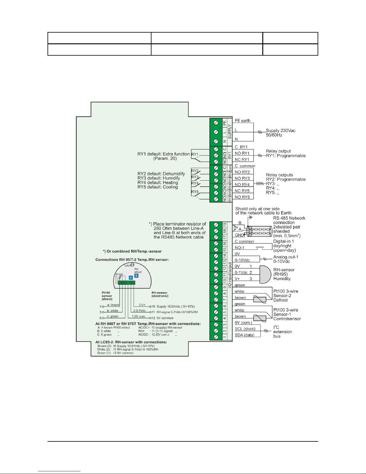
9. Connection diagram.
Connections MC 785 -DF KLIMA ALFANET W allmount drawing 010342
Page 17
Operating manual Document nr. : 010346 Version : V1.4
MC 785-DF KLIMA ALFANET Client : General Page : 17 of 20
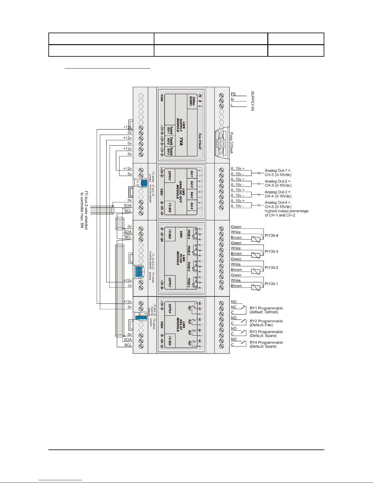
Connection diagram drawing 980224:
LMS Relay Module + LMS 4xPt100 Module + LMS Analog-out Module + LMS Supply Module.
Page 18

Operating manual Document nr. : 010346 Version : V1.4
MC 785-DF KLIMA ALFANET Client : General Page : 18 of 20
Connections MC785-KLIMA ALFANET Panelmount drawing 010348
Page 19
Operating manual Document nr. : 010346 Version : V1.4
MC 785-DF KLIMA ALFANET Client : General Page : 19 of 20
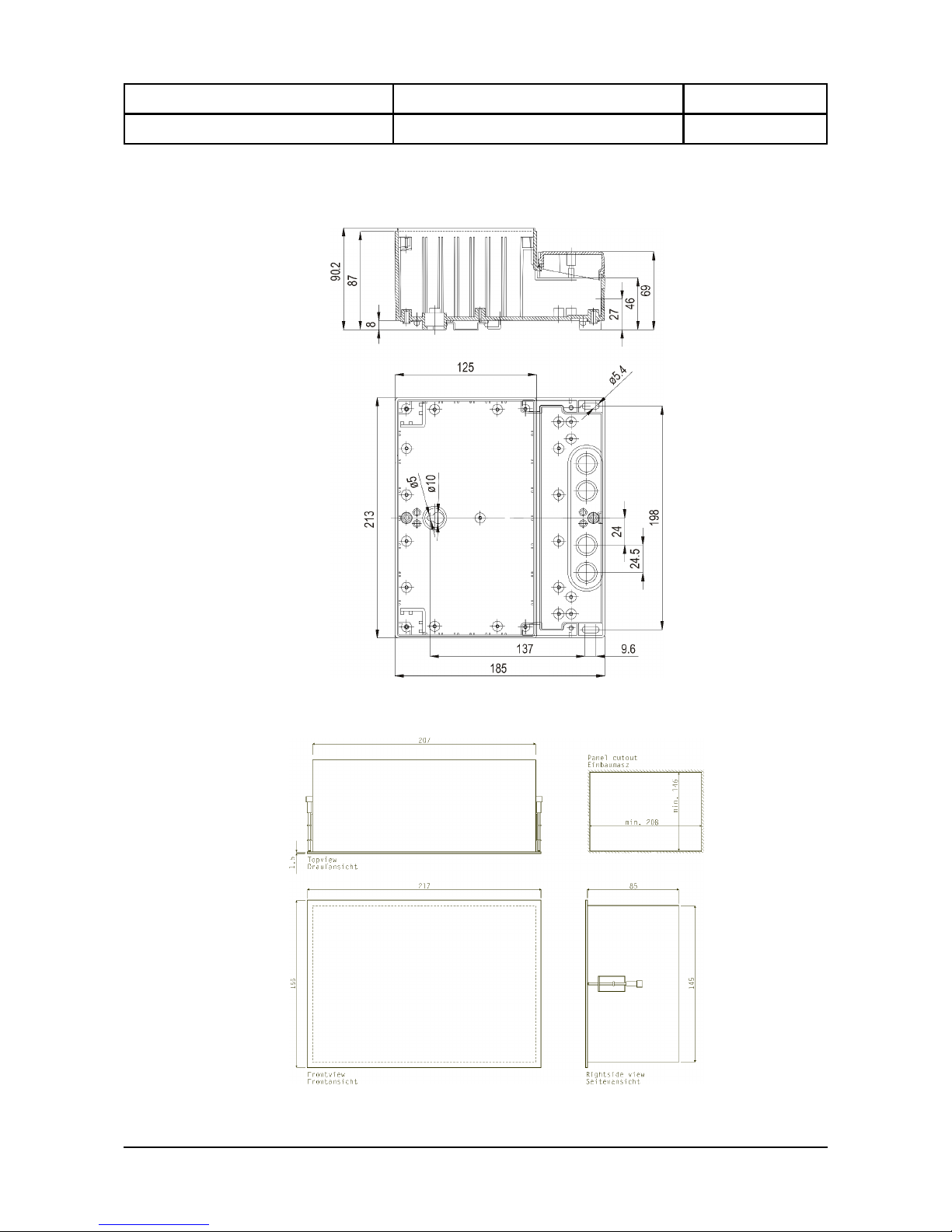
10. Dimensions.
Dimensions MC785-KLIMA W allmount housing
Dimensions MC785-KLIMA Panelmount drawing 961271
Page 20
Operating manual Document nr. : 010346 Version : V1.4
MC 785-DF KLIMA ALFANET Client : General Page : 20 of 20
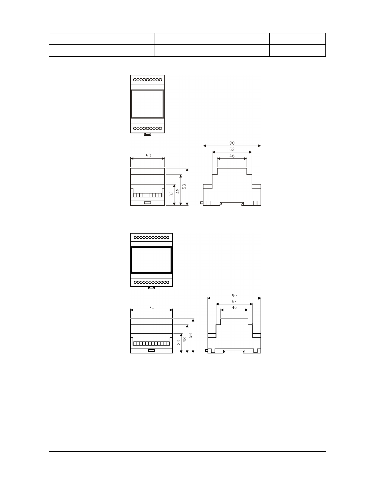
Dimensions LMS Relay Module and LMS Analog-out Module drawing 970983
Dimensions LMS Supply Module and LMS 4xPt100 Module drawing 970908.
-.-.-.-.-.-.-.-.-.-
@
 Loading...