

Page 1

Description: MC 785D Thermostat Doc.nr.: 021171
Type: MANUAL Number of pages: 20 Version: V1.0
File: Do021171 MC785D 0-100'C v10 EN.wp8
Software: MC785D1 (0-100OC) V1.00
By: BJB Date: 06-06-2002
VDH Products BV - Roden - Holland Signed: File: Doc'02
MC 785D
0/+100°C
Operating Manual
wall and panel mounting
Page 2

Operation Manual Document nr. : 021171 Version : V1.0
MC 785D 0/+100OC Client : General Page : 2 of 20
The information contained in this document is assumed to be accurate. However VDH Products BV accepts
no liability for eventual mistakes or errors and has the right to change this document without notice.
Table of contents
1 Technical specifications. . . . . . . . . . . . . . . . . . . . . . . . . . . . . . . . . . . . . . . . . . . . . . . . . . . . . 3
2 Functional specifications. . . . . . . . . . . . . . . . . . . . . . . . . . . . . . . . . . . . . . . . . . . . . . . . . . . . . 4
3 Control of the thermostat. . . . . . . . . . . . . . . . . . . . . . . . . . . . . . . . . . . . . . . . . . . . . . . . . . . . 5
4 Programming internal settings. . . . . . . . . . . . . . . . . . . . . . . . . . . . . . . . . . . . . . . . . . . . . . . . 6
5 Operation relay outputs. . . . . . . . . . . . . . . . . . . . . . . . . . . . . . . . . . . . . . . . . . . . . . . . . . . . . 9
6 Sensor calibration. . . . . . . . . . . . . . . . . . . . . . . . . . . . . . . . . . . . . . . . . . . . . . . . . . . . . . . . . 10
7 Alarms. . . . . . . . . . . . . . . . . . . . . . . . . . . . . . . . . . . . . . . . . . . . . . . . . . . . . . . . . . . . . . . . . 10
8 Advanced Programming. . . . . . . . . . . . . . . . . . . . . . . . . . . . . . . . . . . . . . . . . . . . . . . . . . . . 11
9 Front views. . . . . . . . . . . . . . . . . . . . . . . . . . . . . . . . . . . . . . . . . . . . . . . . . . . . . . . . . . . . . . 16
10 Connection diagrams. . . . . . . . . . . . . . . . . . . . . . . . . . . . . . . . . . . . . . . . . . . . . . . . . . . . . . 17
11 Dimensions. . . . . . . . . . . . . . . . . . . . . . . . . . . . . . . . . . . . . . . . . . . . . . . . . . . . . . . . . . . . . . 19
Page 3

Operation Manual Document nr. : 021171 Version : V1.0
MC 785D 0/+100OC Client : General Page : 3 of 20
1 Technical specifications.
General
Type : MC 785D
Wall mounting:
Housing : Grey plastic
Material : Polystyrol 454h KG 2 natur BASF
Dimensions : 213 x 180 x 85mm (whd)
Front : Polycarbonate (IP-44)
Panel mounting:
Housing : Steel plate panel
Material : Steel in silvergrey
Dimensions : 217 x 155 x 85mm (whd)
Panel cutout : min. 208 x 146mm (wh)
Front : Polycarbonate (IP-44)
Range : 0/+100C per 0,1C
Supply : 230 Vac; 50/60 Hz (-10/+5%).
Used power : 9 VA
Store temperature : -20/+60C
Operation temperature : -20/+50C
Operating rel. humidity : 10/+90 % RH not condensing
Accuracy : ± 0,5 % of the range
Front
Display : 4-number digital display for temperature read-out
4-number digital display for temperature setpoint
LED : F1 = LED Thermostat 1 active
F2 = LED Thermostat 2 active
F3 = LED Thermostat 3 active
F4 = LED Thermostat 4 active
= LED Night mode active
= LED Alarm active
S1 = LED Setpoint 1 in display
S2 = LED Setpoint 2 in display
S3 = LED Setpoint 3 in display
S4 = LED Setpoint 4 in display
Keys : ON/OFF = On/Off key controller
SETP = Setpoint push button
= Up key
= Down key
PRG = Program key
SENS = Sensor read-out key
Page 4

Operation Manual Document nr. : 021171 Version : V1.0
MC 785D 0/+100OC Client : General Page : 4 of 20
In- and outputs
Sensors : Temperature sensor 1 (Pt-100, 3-wire to DIN/IEC 751)
Temperature sensor 2 (Pt-100, 3-wire to DIN/IEC 751)
Temperature sensor 3 (Pt-100, 3-wire to DIN/IEC 751)
Temperature sensor 4 (Pt-100, 3-wire to DIN/IEC 751)
Digital inputs : Night offset input (potential free input contact)
External alarm input (potential free input contact)
Analog output : 2x 0/+10Vdc, Rbmin 10Kohm, programmable.
Relay outputs : RY1 Alarm (C/NO/NC, 250Vac/10A not inductive)
Normally C-NO is closed, at alarm C-NC is closed.
The next relays have a central common;
RY2 Relay 2 programmable (NO, 250Vac/10A not inductive)
RY3 Relay 3 programmable (NO, 250Vac/10A not inductive)
RY4 Relay 4 programmable (NO, 250Vac/10A not inductive)
RY5 Relay 5 programmable (NO, 250Vac/10A not inductive)
2 Functional specifications.
To the MC 785D thermostat a maximum of four temperature sensors can be connected. As more
than one sensor is set active the MC785D controls on the average temperature of these sensors.
A maximum for four different setpoints can be programmed.
The MC785D thermostat has standard functions from 1 thermostat with 1 setpoint and 1 relay output
until 4 thermostats with 4 setpoints and 4 relay outputs. Also two-, three- or four-steps thermostat with
one setpoint available.
The MC 785D has the control functions cooling or heating. Also has the controller an alarm relay,
which becomes active as soon as the alarm levels are exceeded, a sensor is broken or the external
alarm input is closed.
The MC 785D has two analog outputs with a range of 0/+10Vdc. The function of these outputs can be
programmed as measuring signal, setpoint signal or a P(I) control for the cooling or heating.
The controller has two digital input contacts. The first contact is used as night offset input, the second
contact as external alarm.
The above mentioned settings are made via the Internal Parameters.
To allow also other combinations between setpoints, sensor and relays, there is the Advanced
Programming. This mode is only advisable for advanced users.
Page 5

Operation Manual Document nr. : 021171 Version : V1.0
MC 785D 0/+100OC Client : General Page : 5 of 20
3 Control of the thermostat.
Normally the displays show the measured temperature and the selected setpoint.
Switching the thermostat on and off.
With the ON/OFF key the MC 785D can be switched on and off. Is the thermostat switched off,
all displays are off. No control function is active.
Select and change temperature setpoint.
With the UP and DOWN keys the desired setpoint can be selected. The LED's next to the
setpoint display indicate which setpoint is shown.
By pushing the SETPOINT key, the setpoint starts flashing. With the UP and DOWN keys the
setpoint can be changed. By pressing the SETPOINT key again, the new setpoint is accepted.
Read-out and switching sensors on and off.
By pressing the SENS key the temperature of the first sensor is shown in the upper display.
The lower display shows the number of the sensor and of the sensor is switched on or off.
'S1on' means that the temperature of sensor 1 is shown and that the sensor is switched on.
Sensors that are switched on are used for the control, switched off sensors not. If more sensors
for a thermostat are switched on, the control is based on the average of those sensors.
If during the read-out of a sensor is pressed on the SETP key, a sensor can be switched on or
switched off.
By pressing the SENS key once again, the next sensor is shown. After all sensors are shown,
the average measured temperature and the setpoint are shown in the display.
Reset the alarm.
As soon as an alarm situation occurs and an error message appears on the display can, by
pressing the RESET ALARM key, the alarm be reset.
The error message remains in the display, until the cause of the error is solved.
Day/night input.
If the NIGHT input is closed, the MC 785D turns to the night mode. The NIGHT LED will light.
The setpoints are increased with the night offset.
External alarm input.
If the external alarm input is closed, an alarm message “FE” appears in the display. The alarm
relay is activated. By pressing the RESET ALARM key, the alarm be reset. The error message
remains in the display, until the cause of the error is solved.
Page 6

Operation Manual Document nr. : 021171 Version : V1.0
MC 785D 0/+100OC Client : General Page : 6 of 20
4 Programming internal settings.
By pressing the RESET ALARM and SENS key simultaneously for more than 5 seconds, the Internal
Parameter menu is entered. The temperature display shows a P with a number. With the UP and
DOWN key the desired parameter can be selected.
The setpoint display shows the value of the parameter. By pressing the SETPOINT key
simultaneously with the UP or DOWN key, the value can be adjusted.
The parameter table shows the normal programming functions of the thermostat. It is possible to
make other combinations between sensors, setpoints and relays. For these advanced programming
function please see chapter 8 'Advanced Programming'.
If during 30 seconds no key is touched, the display returns to the normal operating mode.
Parameter table.
Number Description Range Value Default
Function of the thermostat
P 01 Function thermostat
0 = 1 setp, 1 relay (D)
1 = 1 setp, 2 relay (D21)
2 = 2 setp, 2 relay (D22)
3 = 1 setp, 3 relay (D31)
4 = 3 setp, 3 relay (D33)
5 = 1 setp, 4 relay (D41)
6 = 4 setp, 4 relay (D44)
0..6 - 0
Settings of the sensors
P 11
P 12
P 13
P 14
P 15
P 16
P 17
P 18
Sensor 1
0 = absent
1 = present
Sensor 2
Sensor 3
Sensor 4
Offset temp. sensor 1
Offset temp. sensor 2
Offset temp. sensor 3
Offset temp. sensor 4
0..1
0..1
0..1
0..1
-10..+10
-10..+10
-10..+10
-10..+10
-
-
-
-
C
C
C
C
0
0
0
0
0.0
0.0
0.0
0.0
Page 7

Operation Manual Document nr. : 021171 Version : V1.0
MC 785D 0/+100OC Client : General Page : 7 of 20
Number Description Range Value Default
Setting of the relays
P 21
P 22
P 23
P 24
P 25
P 26
P 27
P 28
P 29
P 30
P 31
P 32
Function relay 2
0 = cooling
1 = heating
Differential relay 2
Offset relay 2
Function relay 3
Differential relay 3
Offset relay 3
Function relay 4
Differential relay 4
Offset relay 4
Function relay 5
Differential relay 5
Offset relay 5
0..1
0.1..15.0
-15..+15
0..1
0.1..15.0
-15..+15
0..1
0.1..15.0
-15..+15
0..1
0.1..15.0
-15..+15
-
C
C
-
C
C
-
C
C
-
C
C
0
0.5
0.0
0
0.5
0.0
0
0.5
0.0
0
0.5
0.0
Setting of the alarm
P 41
P 42
P 43
P 44
P 45
P 46
P 47
P 48
P 49
Type temperature alarm
0 = No alarm
1 = Absolute alarm
2 = Relative to setpoint
Minimum alarm temperature
Maximum alarm temperature
Minimum alarm delay
Maximum alarm delay
Temperature control off
during minimum alarm
Temperature control off
during minimum alarm
Temperature control off
if all sensors at fault
Control off during external
alarm
0..2
0..+100
0..+100
0..99
0..99
0 = no
1 = yes
0 = no
1 = yes
0 = no
1 = yes
0 = no
1 = yes
-
C
C
minutes
minutes
-
-
-
-
1
0.0
+100.0
0
0
0
0
0
0
Display and setpoint
P 51
P 52
P 53
P 54
P 55
Minimum setpoint value
Maximum setpoint value
Read-out above -10C per
1C
Read-out below -10C per
1C
Offset night shift
0.0..+100.0
0.0..+100.0
0 = no
1 = yes
0 = no
1 = yes
-15..+15
C
C
-
-
C
0.0
+100.0
0
1
0.0
Page 8

Operation Manual Document nr. : 021171 Version : V1.0
MC 785D 0/+100OC Client : General Page : 8 of 20
Number Description Range Value Default
Setting analog outputs
P 61
P 62
P 63
P 64
P 65
P 66
P 71
P 72
P 73
P 74
P 75
P 76
Function analog output 1
0 = Average control temp.
1 = Setpoint
2 = P(I) cooling
3 = P(I) heating
0 V out at
10 V out at
Proportional band
Offset prop. band
Intergral value
(999 gives only P)
Function analog output 2
0 = Average control temp.
1 = Setpoint
2 = P(I) cooling
3 = P(I) heating
0 V out at
10 V out at
Proportional band
Offset prop. band
Intergral value
(999 gives only P)
0..3
-100..+100
-100..+100
0.1..15
-15..+15
1..999
0..3
-100..+100
-100..+100
0.1..15
-15..+15
1..999
-
-
-
-
minutes
-
-
-
-
minutes
0
0.0
+100.0
1.0
0.0
999
0
0.0
+100.0
1.0
0.0
999
Production details
P 91
P 92
P 93
Software version number
Serial number
Production date
-
-
-
-
year/wk
-
-
Page 9

Operation Manual Document nr. : 021171 Version : V1.0
MC 785D 0/+100OC Client : General Page : 9 of 20
5 Operation relay outputs.
Function selection of the thermostat.
With parameter P 01 the function of the thermostat is selected.
0 (D) = 1-stage thermostat with one setpoint and one relay output.
1 (D21) = 2-stage thermostat with one setpoint and two relay outputs.
2 (D22) = 2 thermostats each with his own setpoint and relay output.
3 (D31) = 3-stage thermostat with one setpoint and two relay outputs.
4 (D33) = 3 thermostats each with his own setpoint and relay output.
5 (D41) = 4-stage thermostat with one setpoint and two relay outputs.
6 (D44) = 4 thermostats each with his own setpoint and relay output.
All these thermostats control on the average temperature off the active sensors.
Operation of the cooling and heating.
For each relay the function cooling or heating can be programmed.
The cooling switches on if the temperature is higher than the setpoint + offset cooling +
differential cooling and switches off if the temperature is below setpoint + offset cooling.
The heating switches on if the temperature is lower than the setpoint + offset heating -
differential heating and switches off if the temperature is above setpoint + offset heating.
Operation of the alarm.
A selection can be made between no alarm, absolute alarm and relative alarm (P 41).
At an absolute alarm an alarm message will follow as soon as one of the active sensor exceeds
the alarm levels. The time delay prevents that an alarm will follow if e.h. the door of the cold
room is opened shortly.
The relative alarm are linked to the setpoint. A relative maximum alarm follows if one of the
active sensors has a temperature which is higher than setpoint + maximum alarm
temperature, taking the time delay into account. A relative minimum alarm follows if one of the
active sensors has a temperature which is lower than setpoint - minimum alarm temperature,
taking the time delay into account.
Display and setpoint.
The range over which the setpoint can be set, can be limited with parameter P 51 and P52.
Also a read-out per 0,1°C or per 1°C can be selected.
Page 10

Operation Manual Document nr. : 021171 Version : V1.0
MC 785D 0/+100OC Client : General Page : 10 of 20
6 Sensor calibration.
With the parameters P15 to P18 the temperature sensors can be calibrated. Indicates temperature
sensor 1 e.g. 0,2°C too much, the offset (P 15) should be set at -0,2°C.
7 Alarms.
In normal position the alarm relay is on and drops during alarm. This to give an alarm if there is a
power failure. During alarm the alarm LED on the front flashes. Depending on the settings of the
Internal Parameters the control will stop or continue.
An alarm can be caused by:
Temperature alarm : tLO = Minimum alarm temperature
tHI = Maximum alarm temperature
External alarm : FE = External alarm
Sensor failure : F1 = No Temperature sensor on Thermostat-1
F2 = No Temperature sensor on Thermostat-2
F3 = No Temperature sensor on Thermostat-3
F4 = No Temperature sensor on Thermostat-4
E1 = Temperature sensor 1 broken
E2 = Temperature sensor 2 broken
E3 = Temperature sensor 3 broken
E4 = Temperature sensor 4 broken
EA = All control sensors at fault
By pressing the RESET ALARM key, the alarm relay is reset. The error message will remain in the
display until the alarm is solved. Also the alarm LED will remain flashing.
Page 11

Operation Manual Document nr. : 021171 Version : V1.0
MC 785D 0/+100OC Client : General Page : 11 of 20
8 Advanced Programming.
By pressing the SETP. and SENS key simultaneously for more than 5 seconds, the Advanced
Parameter menu is entered. The temperature display shows an A with a number. With the UP and
DOWN key the desired parameter can be selected. At first A001 must be set to 1 to make the
Advanced Programming active.
Now all A... parameters can be set. All P... parameters are not active, they can’t be looked at or
changed (Only as A001 =0 the P.. Parameters can be set or shown again).
The setpoint display shows the value of the parameter. By pressing the SETPOINT key
simultaneously with the UP and DOWN key, the value can be adjusted.
If during 30 seconds no key is touched, the display returns to the normal operating mode.
Unless stated else, 0 = NO and 1 = YES.
Parameter table.
Number Description Range Value Default
General
A 001
A 002
A 003
A 004
Advanced programming active
Software version number
Serial number
Production date
0..1
-
-
-
-
-
year/wk
0
-
-
Number of thermostats
A 010
A 011
A 012
Number of thermostats
Thermostat 1 is used as
differential thermostat
Thermostat 2 is used as
differential thermostat
1..4
0..1
0..1
-
-
-
1
0
0
Sensor assignment
A 110
A 120
A 130
A 140
Sensor 1
0 = not present
1 = thermostat 1
2 = thermostat 2
3 = thermostat 3
4 = thermostat 4
5 = thermostat 1 & 2
6 = thermostat 1 & 3
7 = thermostat 1 & 4
8 = thermostat 2 & 3
9 = thermostat 2 & 4
10 = thermostat 3 & 4
11 = thermostat 1, 2 & 3
12 = thermostat 1, 2 & 4
13 = thermostat 1, 3 & 4
14 = thermostat 2, 3 & 4
15 = thermostat 1, 2, 3 & 4
Sensor 2
Sensor 3
Sensor 4
0..15
0..15
0..15
0..15
-
-
-
-
1
1
1
1
When Thermostat 1 is used as differential thermostat it controls on the differential
temperature of sensor 1 minus sensor 2.
When Thermostat 2 is used as differential thermostat it controls on the differential
temperature of sensor 3 minus sensor 4.
The sensor has to be assigned accordantly.
Page 12

Operation Manual Document nr. : 021171 Version : V1.0
MC 785D 0/+100OC Client : General Page : 12 of 20
Number Description Range Value Default
Sensor offset
A 210
A 220
A 230
A 240
Offset temperature sensor 1
Offset temperature sensor 2
Offset temperature sensor 3
Offset temperature sensor 4
-10..+10
-10..+10
-10..+10
-10..+10
C
C
C
C
0.0
0.0
0.0
0.0
Relay assignment
A 310
A 320
A 330
A 340
Relay 2
0 = not assigned
1 = thermostat 1
2 = thermostat 2
3 = thermostat 3
4 = thermostat 4
5 = thermostat 1 & 2
6 = thermostat 1 & 3
7 = thermostat 1 & 4
8 = thermostat 2 & 3
9 = thermostat 2 & 4
10 = thermostat 3 & 4
11 = thermostat 1, 2 & 3
12 = thermostat 1, 2 & 4
13 = thermostat 1, 3 & 4
14 = thermostat 2, 3 & 4
15 = thermostat 1, 2, 3 & 4
Relay 3
Relay 4
Relay 5
0..15
0..15
0..15
0..15
-
-
-
-
1
1
1
1
Function of thermostats
A 410
A 420
A 430
A 440
A 510
A 511
A 520
A 521
A 530
A 531
A 540
A 541
Function thermostat 1
0 = cooling
1 = heating
Function thermostat 2
Function thermostat 3
Function thermostat 4
Differential thermostat 1
Offset thermostat 1
Differential thermostat 2
Offset thermostat 2
Differential thermostat 3
Offset thermostat 3
Differential thermostat 4
Offset thermostat 4
0..1
0..1
0..1
0..1
0.1..15.0
-15..+15
0.1..15.0
-15..+15
0.1..15.0
-15..+15
0.1..15.0
-15..+15
-
-
-
-
C
C
C
C
C
C
C
C
0
0
0
0
0.5
0.0
0.5
0.0
0.5
0.0
0.5
0.0
Page 13

Operation Manual Document nr. : 021171 Version : V1.0
MC 785D 0/+100OC Client : General Page : 13 of 20
Number Description Range Value Default
Setting of the alarms
A 610
A 611
A 612
A 613
A 614
A 615
A 616
A 620
A 621
A 622
A 623
A 624
A 625
A 626
A 630
A 631
A 632
A 633
A 634
A 635
A 636
A 640
A 641
A 642
A 643
A 644
A 645
A 646
A 650
A 651
Alarm setting thermostat 1
0 = No alarm
1 = Absolute alarm
2 = Relative alarm
Minimum alarm temperature
Maximum alarm temperature
Minimum alarm delay
Maximum alarm delay
Control off at minimum alarm
Control off at maximum alarm
Alarm setting thermostat 2
Minimum alarm temperature
Maximum alarm temperature
Minimum alarm delay
Maximum alarm delay
Control off at minimum alarm
Control off at maximum alarm
Alarm setting thermostat 3
Minimum alarm temperature
Maximum alarm temperature
Minimum alarm delay
Maximum alarm delay
Control off at minimum alarm
Control off at maximum alarm
Alarm setting thermostat 4
Minimum alarm temperature
Maximum alarm temperature
Minimum alarm delay
Maximum alarm delay
Control off at minimum alarm
Control off at maximum alarm
Temperature control off if all
control sensors at fault
Temperature control off at
external alarm
0..2
0..+100
0..+100
0..99
0..99
0..1
0..1
0..2
0..+100
0..+100
0..99
0..99
0..1
0..1
0..2
0..+100
0..+100
0..99
0..99
0..1
0..1
0..2
0..+100
0..+100
0..99
0..99
0..1
0..1
0..1
0..1
-
C
C
minutes
minutes
-
-
-
C
C
minutes
minutes
-
-
-
C
C
minutes
minutes
-
-
-
C
C
minutes
minutes
-
-
0
0.0
+100.0
0
0
0
0
0
0.0
+100.0
0
0
0
0
0
0.0
+100.0
0
0
0
0
0
0.0
+100.0
0
0
0
0
0
0
Display and setpoint
A 710
A 711
A 712
A 713
A 714
A 720
A 721
A 722
A 723
A 724
Minimum setpoint thermostat 1
Maximum setpoint thermostat 1
Read-out above -10C per 1C
Read-out below -10C per 1C
Offset night mode thermostat 1
Minimum setpoint thermostat 2
Maximum setpoint thermostat 2
Read-out above -10C per 1C
Read-out below -10C per 1C
Offset night mode thermostat 2
0..+100
0..+100
0..1
0..1
-15..+15
0..+100
0..+100
0..1
0..1
-15..+15
C
C
-
-
C
C
C
-
C
0.0
+100.0
0
0
0.0
0.0
+100.0
0
0
0.0
Page 14

Operation Manual Document nr. : 021171 Version : V1.0
MC 785D 0/+100OC Client : General Page : 14 of 20
Number Description Range Value Default
A 730
A 731
A 732
A 733
A 734
A 740
A 741
A 742
A 743
A 744
Minimum setpoint thermostat 3
Maximum setpoint thermostat 3
Read-out above -10C per 1C
Read-out below -10C per 1C
Offset night mode thermostat 3
Minimum setpoint thermostat 4
Maximum setpoint thermostat 4
Read-out above -10C per 1C
Read-out below -10C per 1C
Offset night mode thermostat 4
0..+100
0..+100
0..1
0..1
-15..+15
0..+100
0..+100
0..1
0..1
-15..+15
C
C
-
-
C
C
C
-
C
0.0
+100.0
0
0
0.0
0.0
+100.0
0
0
0.0
Analog output 1
A 810
A 811
A 812
A 813
A 814
A 815
A 816
Function analog output 1
0 = Control temp. thermostat 1
1 = Control temp. thermostat 2
2 = Control temp. thermostat 3
3 = Control temp. thermostat 4
4 = Setpoint thermostat 1
5 = Setpoint thermostat 2
6 = Setpoint thermostat 3
7 = Setpoint thermostat 4
8 = Temperature sensor 1
9 = Temperature sensor 2
10 = Temperature sensor 3
11 = Temperature sensor 4
12 = P(ID) cooling thermost. 1
13 = P(ID) cooling thermost. 2
14 = P(ID) cooling thermost. 3
15 = P(ID) cooling thermost. 4
16 = P(ID) heating thermost. 1
17 = P(ID) heating thermost. 2
18 = P(ID) heating thermost. 3
19 = P(ID) heating thermost. 4
0 V out at
10 V out at
Proportional band
Offset proportional band
Intergral value (999 = P)
Differential value
0..19
-100..+100
-100..+100
0.1..15
-15..+15
1..999
0..999
-
-
-
-
minutes
minutes
0
0.0
+100.0
1.0
0.0
999
0
Page 15

Operation Manual Document nr. : 021171 Version : V1.0
MC 785D 0/+100OC Client : General Page : 15 of 20
Number Description Range Value Default
Analog output 2
A 820
A 821
A 822
A 823
A 824
A 825
A 826
Function analog output 2
0 = Control temp. thermostat 1
1 = Control temp. thermostat 2
2 = Control temp. thermostat 3
3 = Control temp. thermostat 4
4 = Setpoint thermostat 1
5 = Setpoint thermostat 2
6 = Setpoint thermostat 3
7 = Setpoint thermostat 4
8 = Temperature sensor 1
9 = Temperature sensor 2
10 = Temperature sensor 3
11 = Temperature sensor 4
12 = P(ID) cooling thermost. 1
13 = P(ID) cooling thermost. 2
14 = P(ID) cooling thermost. 3
15 = P(ID) cooling thermost. 4
16 = P(ID) heating thermost. 1
17 = P(ID) heating thermost. 2
18 = P(ID) heating thermost. 3
19 = P(ID) heating thermost. 4
0 V out at
10 V out at
Proportional band
Offset proportional band
Intergral value (999 = P)
Differential value
0..19
-100..+100
-100..+100
0.1..15
-15..+15
1..999
0..999
-
-
-
-
minutes
minutes
0
0.0
+100.0
1.0
0.0
999
0
Page 16
Operation Manual Document nr. : 021171 Version : V1.0
MC 785D 0/+100OC Client : General Page : 16 of 20
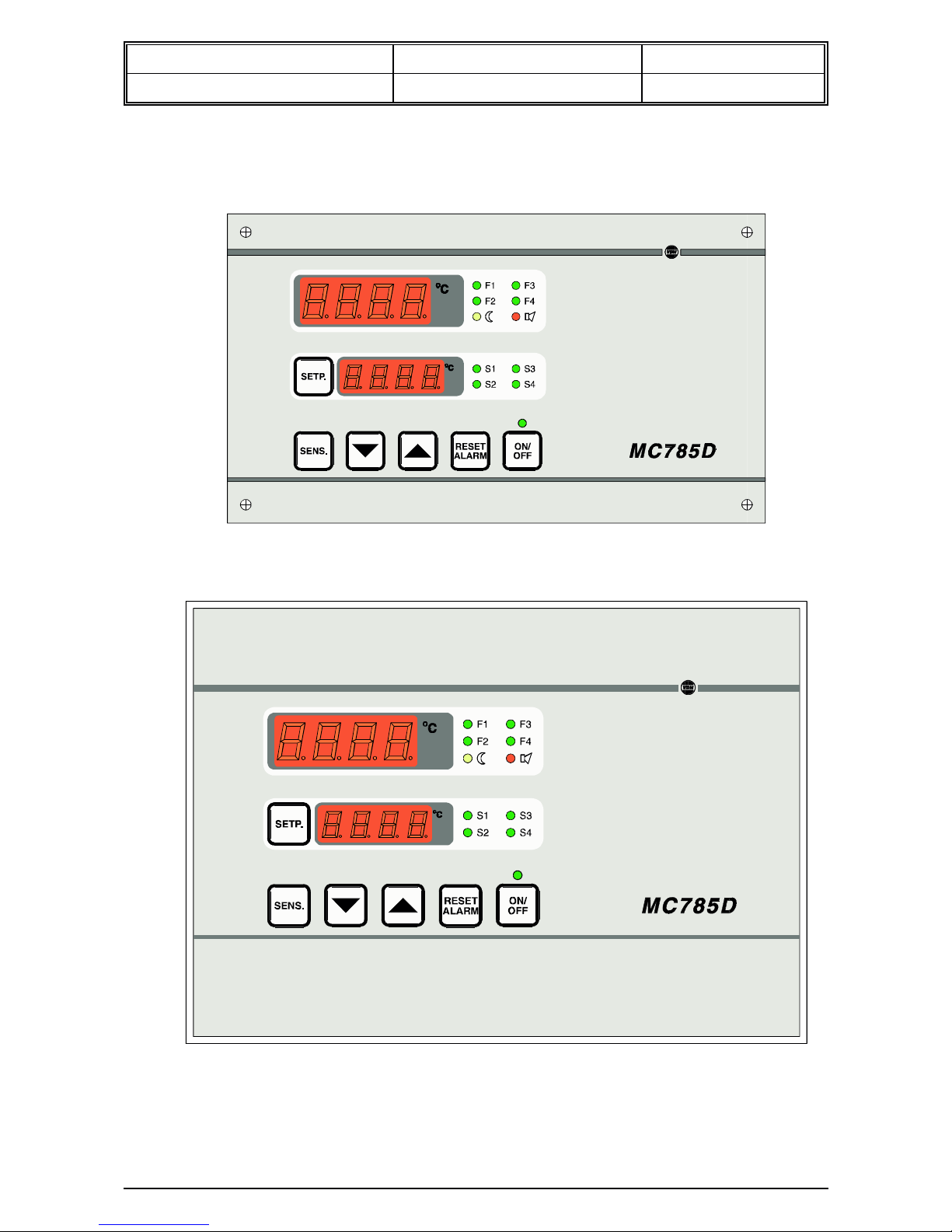
9 Front views.
Front view MC 785-D wall mount drawing 961462
Front view MC 785-D panel mount drawing 981698
Page 17
Operation Manual Document nr. : 021171 Version : V1.0
MC 785D 0/+100OC Client : General Page : 17 of 20
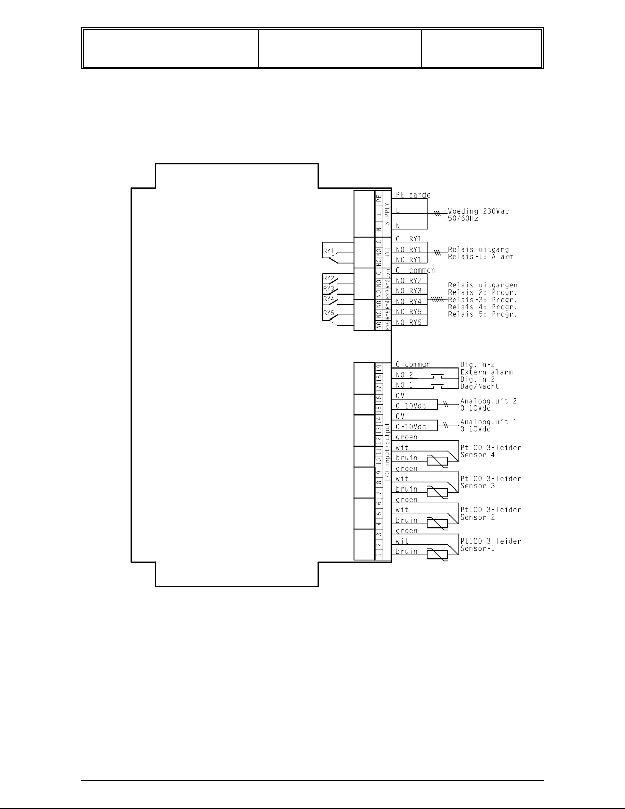
10 Connection diagrams.
Connection diagram MC785-D wall mount drawing 961461
Page 18
Operation Manual Document nr. : 021171 Version : V1.0
MC 785D 0/+100OC Client : General Page : 18 of 20
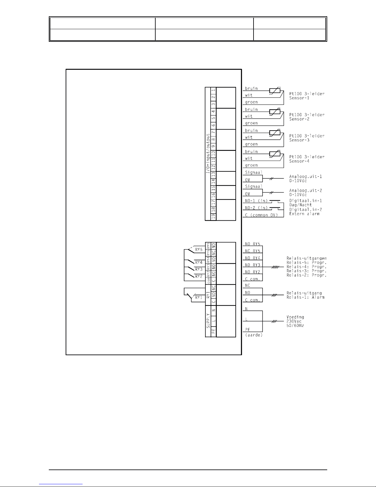
Connection diagram MC785-D panel mount drawing 981710
Page 19

Operation Manual Document nr. : 021171 Version : V1.0
MC 785D 0/+100OC Client : General Page : 19 of 20
11 Dimensions.
Dimensions Wall mount drawing 940024
Page 20

Operation Manual Document nr. : 021171 Version : V1.0
MC 785D 0/+100OC Client : General Page : 20 of 20
Dimensions Panel mount drawing 961271
-.-.-.-.-.-.-.-.-.
@
 Loading...