

Page 1
Description
:
LNG EXT RS_OS/OG Vimar Eikon 3M Z
Pages: 6
Doc.nr:
150899 Type:
Installation m
anual
By: DE Version: 1.1 File:
Do150899 LNG EXT RS_OS
-
OG Vimar
Eikon 3M Z Installation manual V11
EN.docx
Date: 24-05-2015
LNG EXT RS_OS
/OG
Vimar Eikon 3M Z
Installation manual
1 Introduction
This installation manual describes the functioning and
installation of the following control panels:
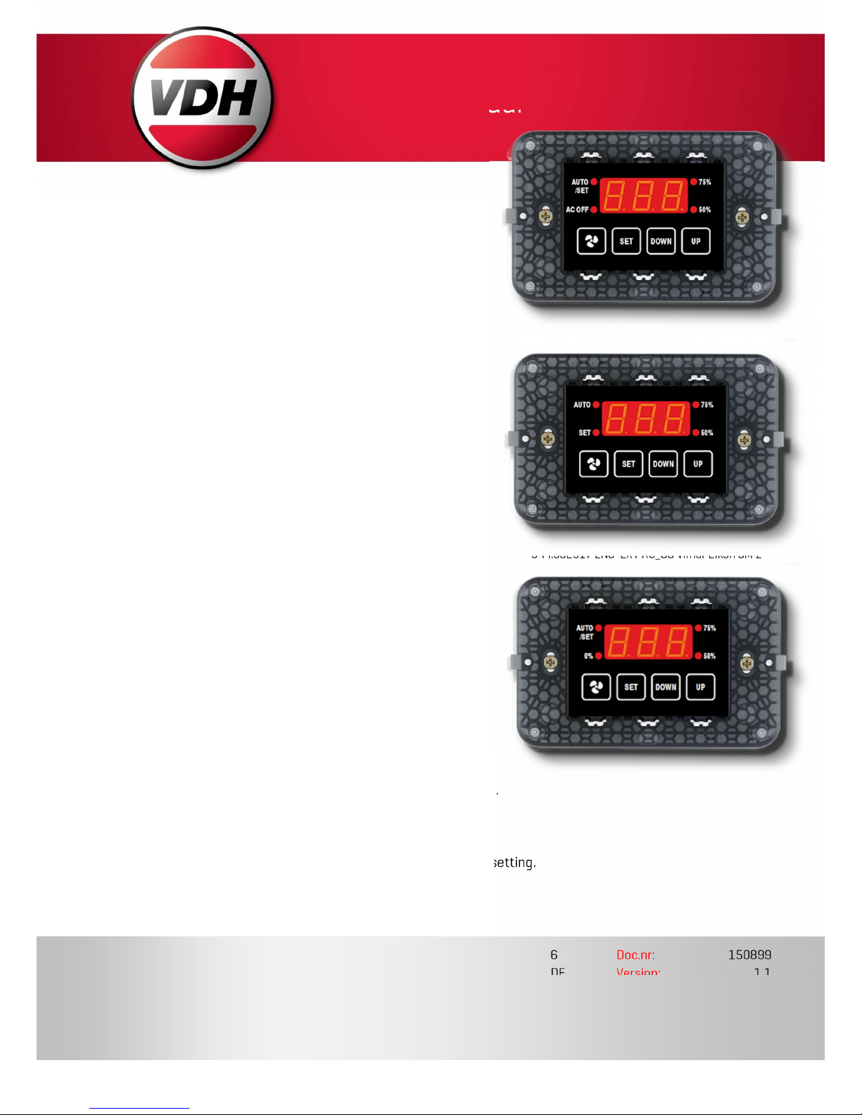
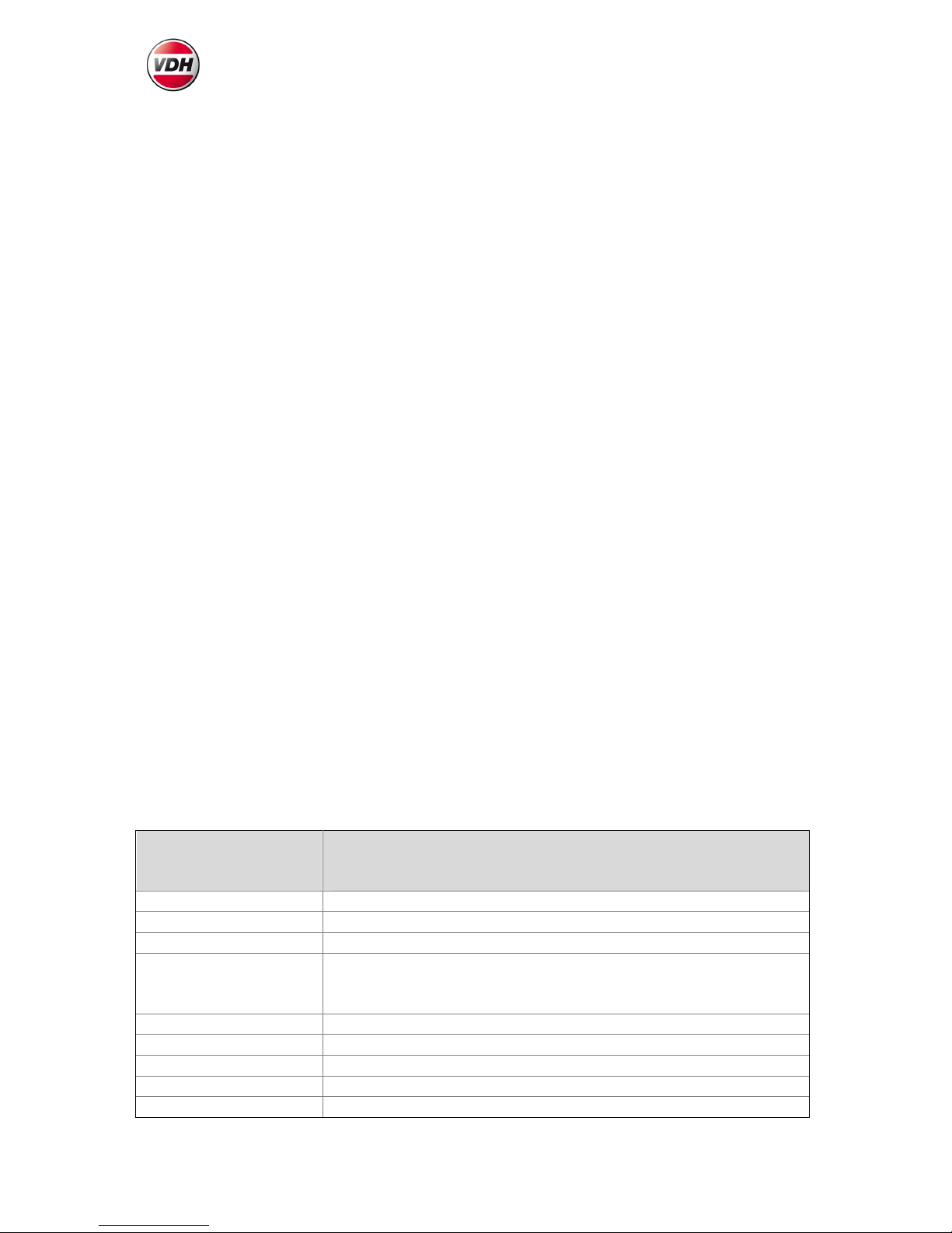
944.802516 LNG EXT RS_OS Vimar Eikon 3M Z
944.802517 LNG EXT RS_OG Vimar Eikon 3M Z
944.802662 LNG EXT RS_OS Vimar Eikon 3M Z
The control panels have a sensor input for an external
temperature sensor. A fan speed setting and set point can
be set by the end user.
These settings can be read out and set through the
RS485-communication bus (Modbus ASCII protocol).
2 Installation
See the connection diagram for the electrical connections
of the control panel.
3 Operating instructions
The control panel has 4 keys:
FAN MODE - change fan speed setting.
SET - view/change temperature set point setting.
DOWN - decrease selected setting value.
UP - increase selected setting value.
The leds next to the displays indicate the current fan speed setting.
944.802516 LNG EXT RS_OS Vimar Eikon 3M Z
944.80251
7 LNG EXT RS_O
G Vimar Eikon 3M Z
944.802
662 LNG EXT RS_O
S Vimar Eikon 3M Z
Page 2
LNG EXT RS_OS/RS_OG Vimar Eikon 3M Z Doc.nr.: 150899 Version 1.1
Page 2 of 6
3.1 Adjust temperature set point
Use the SET key to view the current temperature set point value. To change the temperature
set point, keep the SET key pressed and use the UP and/or DOWN keys to change the value.
In temperature set point mode, the SET led will blink.
If, for 10 seconds, no key is pressed the control panel will return to normal display mode.
3.2 Change fan speed setting
Use the Fan mode key to change the fan speed setting. If the key is pressed, the led
indicating the current fan speed setting will blink for 4 seconds.
Pressing the key again will change the fan speed setting.
If, for 4 seconds, no key is pressed the selected setting is applied.
3.3 Switching display on/off
(944.802662 only)
Press the Fan mode key for more than 8 seconds to switch the display on or off.
After switching to on, the fan mode will start in the auto setting.
4 Setting display offset
Use parameter P03 to set a display offset for the measured temperature value.
5 Error codes
The control panel can show the following error codes:
LO - Temperature minimum alarm (measured temperature under 5 °C / 41 °F).
HI - Temperature maximum alarm (measures temperature above 35 °C / 95 °F).
6 Technical data
Type 944.802516
LNG EXT RS_OS Vimar Eikon 3M Z
944.802517 LNG EXT RS_OG Vimar Eikon 3M Z
944.802662 LNG EXT RS_OS Vimar Eikon 3M Z
Temperaure range
5..35 °C / 41..95°F
display resolution 0,1°C / °F
Power supply
12..
24 VDC Temperature
Sensor
KTY81
2-wire external
VDH SM811
Communication
RS485
Gnd, A, B
Modbus ASCII
9600 baud 8 N 1
Display
3x 7-segment led displays
Keys
4x key
LED’s
4x Indication LED’s
Front
sticker
Polycarbonat
e Housing
Panel mount (Vimar Eikon system)
Page 3

LNG EXT RS_OS/RS_OG Vimar Eikon 3M Z Doc.nr.: 150899 Version 1.1
Page 3 of 6
7 Internal parameters
To enter the internal parameter mode, keep the DOWN key pressed for more than 10 seconds.
Use the UP and DOWN keys to select a parameter number. To show the value of the selected
number, press the SET key. To change the value of the selected parameter, keep the SET key
pressed and use the UP and/or DOWN keys to change the value.
If no key is pressed, the control panel will return to normal display mode after 20 seconds.
7.1 Parameter table
Number
Descrip
tion Range
Default value
01
Temperature set point minimum value
9.0..29°C
48.2..84.2°F
9.0°C
48.2°F
02 Temperature set point maximum value
9.0..29°C
48.2..84.2°F
29.0°C
84.2°F
03 Temperature display offset
-9.0..+9.0°C
15.8..+48.2°F
0.0°C
32.0°F
04 Network number
1..99
1 06
Display illumination setting
0..30
30 07
Display off delay (0 = never off)
0..900 sec.
0 08
Temperature display unity
0 = °C
1 = °F
0 95 Software version
- - 96
Production year
- - 97
Production week
- - 98
Serial number
(x1000)
- - 99
Serial number (units)
- -
Page 4

LNG EXT RS_OS/RS_OG Vimar Eikon 3M Z Doc.nr.: 150899 Version 1.1
Page 4 of 6
8 Network protocol
The control panel uses the Modbus ASCII-protocol for communication.
The message format is:
[:] {net number}
{function code
} {data bytes}
{LCR}
[CR] [LF]
Each byte {} is sent as two hexadecimal ASCII (0..F) characters.
LCR is the checksum. The checksum is generated by determining the sum of the message bytes.
(excluding [:],[CR] and [LF]).
This checksum is send negated (2's complement).
Check checksum: the sum of all bytes (including checksum) must be 0 (zero).
The network number 0 is reserved (broadcast network number).
Temperature value s are sent per 0,1° tot prevent decimal signs.
Also, temperature values are sent in a special format to make conversion to °C or °F easier:
Value to temperature in °C: temperature = value / 9
Value to temperature in °F: temperature = (value / 5) + 320
8.1 Modbus registers
Read set point
Request :
Byte 0 : FC = 0x03
Byte 1-2: Address (always 0)
Byte 3-4: Number (always 1)
Response:
Byte 0 : FC = 0x03
Byte 1 :Number of bytes (2)
Byte 2-n: Value
Exceptions:
Byte 0 : FC = 0x83
Byte 1 : 0x02 (Illegal
address)
Write set point
Request :
Byte 0 : FC = 0x06
Byte 1-2: Address (Always 0)
Byte 3-4: New value
Response:
Byte 0 : FC = 0x06
Byte 1-2: Address
Byte 3-4: New value
Exceptions:
Byte 0: FC = 0x86
Byte 1: 0x02 (Illegal address)
0x03 (Illegal value)
Readout actual value
Page 5

LNG EXT RS_OS/RS_OG Vimar Eikon 3M Z Doc.nr.: 150899 Version 1.1
Page 5 of 6
Read fan speed setting
Request :
Byte 0 : FC = 0x03
Byte 1-2: Address (always 1)
Byte 3-4: Number (always 1)
Response:
Byte 0 : FC = 0x03
Byte 1 :Number of bytes (2)
Byte 2-n: Value
944.802516:
10 = AUTO
11 = 7 5%
12 = 50 %
13 = AC OFF
944.802517:
20 = AUTO
21 = 7 5%
22 = 50 %
944.802662:
30 = AUTO
31 = 75 %
32 = 50 %
33 = 0 %
34 = AC OFF
Exceptions:
Byte 0 : FC = 0x83
Byte 1 : 0x02 (Illegal
address)
Write fan speed setting
Request :
Byte 0 : FC = 0x06
Byte 1-2: Address (Always 1)
Byte 3-4: New value
Response:
Byte 0 : FC = 0x06
Byte 1-2: Address
Byte 3-4: New value
Exceptions:
Byte 0: FC = 0x86
Byte 1: 0x02 (Illegal address)
0x03 (Illegal value)
Readout actual value
Read measured temperature value
Request :
Byte 0 : FC = 0x04
Byte 1-2: Address (Always 0)
Byte 3-4: Number (Always 1)
Response:
Byte 0 : FC = 0x04
Byte 1 : Number of bytes 2
Byte 2-n: Value
Exceptions:
Byte 0 : FC = 0x84
Byte 1 : 0x02 (Illegal adress)
Request slave ID
Request :
Byte 0 : FC = 0x11
Response:
Byte 0 : FC = 0x11
Exceptions:
None
Page 6

LNG EXT RS_OS/RS_OG Vimar Eikon 3M Z Doc.nr.: 150899 Version 1.1
Page 6 of 6
9 Connection diagram
Drawing 150652w1.
10 Contact
VDH Products B.V.
Tel.: +31 (0)50
– 30
28 900
Productieweg 1
Fax.: +31 (0)50
– 30 28 980
9301 ZS Roden
Email:
info@vdhproducts.nl
Holland
Internet:
www.vdhproducts.nl
 Loading...