

Page 1
0087655 v007 User manual
AL
FA 5
3-Grasso
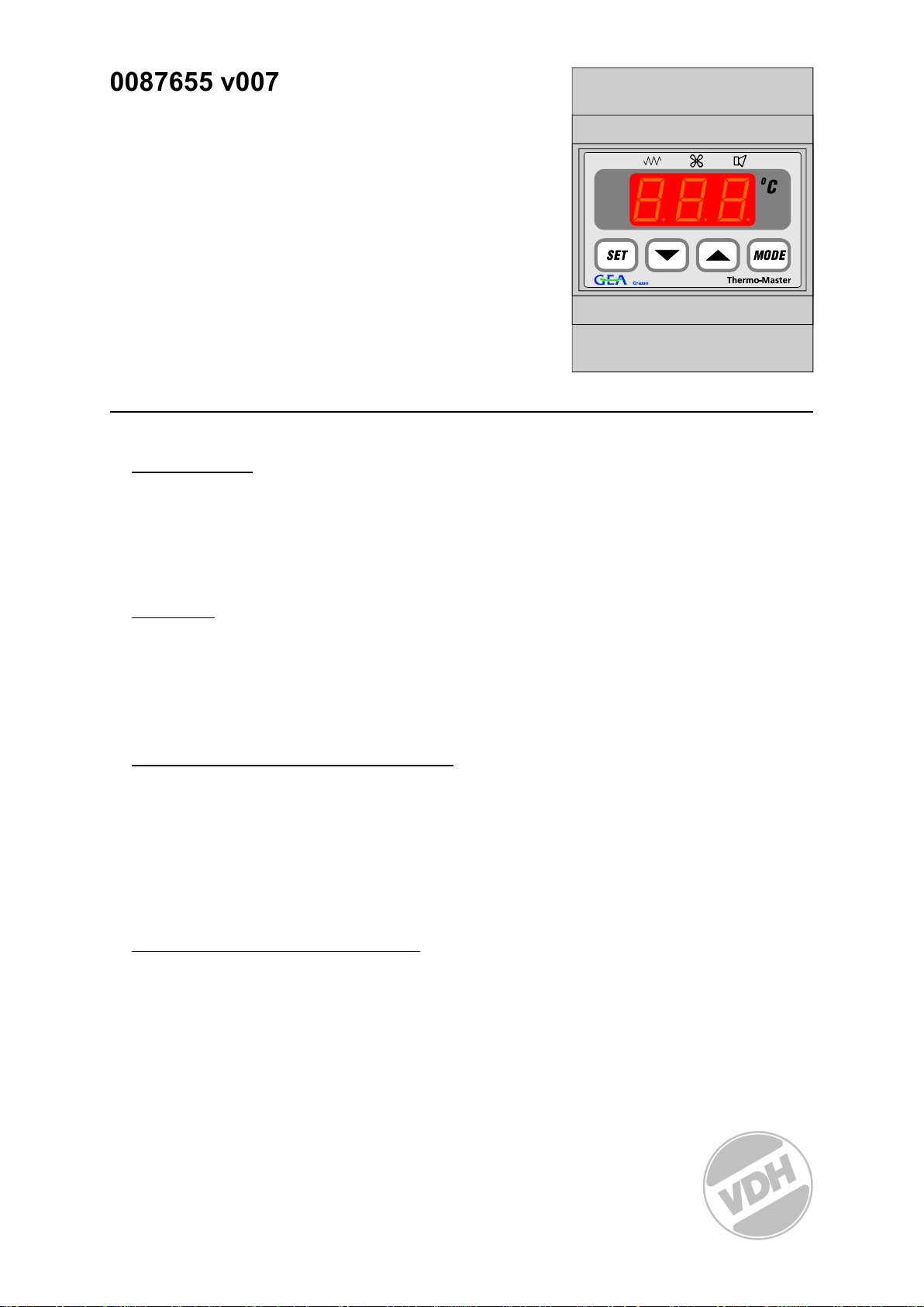
Thermo-Master
Compressor unit with
PCB for sensor inputs.
VDH doc: 040114 Version: v1.8 Date: 09-11-2006
Software: ALFA 53-GR_V1.09 File: Do040114.WP8 Range: 0/+200C, per 1C
* Installation.
On the con
network (to the sensor-pcb), contact input and relays have to be connected.
After connecting the ALFA 53-Grasso to the power supply, a self test function is started. As
this test is finished, the measured oil temperature appears in the display.
nection diagram of the ALFA 53-Grasso you can see how the power supply,
* Control.
The ALFA 53-
SET - view / change cylinder temperatures.
UP - increase a value and reset of alarm.
DOWN - decrease a value.
MODE - view status of relays.
Grasso alarm thermostat can be controlled by four pushbuttons on the front;
* Viewing cylinder temperatures.
By pushing the SET k
in the display to indicate this. By pushing the MODE key the actual value of this sensor in
viewed in the display.
You can select another cylinder temperature by pushing the UP and/or DOWN key. The
displays shows the according cylinder temperature number f.i. ‘S2', ‘S3'.
A few seconds after releasing the keys the cylinder temperature disappears and the
measured oil temperature is shown again in the display.
ey the first cylinder temperature sensor is selected and ‘S1' appears
* Setting internal parameters.
Next
to viewing the cylinder temperatures, some internal settings are possible like number
of cylinders, maximum cylinder temperature.
By pushing the DOWN key more than 10 seconds, you enter the 'internal programming
menu'. In the left display the upper and lower segment, are blinking. Over the UP and DOWN
keys the required parameter can be selected (see parameters table). If the required
parameter is selected, the value can be read-out by pushing the SET key. Pushing the UP
and/or DOWN key all ows you to change the value of this parameter. If after 20 seconds no
key is pushed, the ALFA 53-Grasso changes to its normal operation mode.
1
Page 2

r
* Er
or messages.
th
e display of the ALFA 53-Grasso the following error messages can appear:
In
Sensor errors;
E0 - Oil
E1 - Cylinder Sensor-1 failure. A1 - Maximum alarm Cylinder Sensor-1
E2 - Cylinder Sensor-2 failure. A2 - Maximum alarm Cylinder Sensor-2
E3 - Cylinder Sensor-3 failure. A3 - Maximum alarm Cylinder Sensor-3
E4 - Cylinder Sensor-4 failure. A4 - Maximum alarm Cylinder Sensor-4
E5 - Cylinder Sensor-5 failure. A5 - Maximum alarm Cylinder Sensor-5
E6 - Cylinder Sensor-6 failure. A6 - Maximum alarm Cylinder Sensor-6
E7 - Cylinder Sensor-7 failure. A7 - Maximum alarm Cylinder Sensor-7
E8 - Cylinder Sensor-8 failure. A8 - Maximum alarm Cylinder Sensor-8
E9 - Cylinder Sensor-9 failure. A9 - Maximum alarm Cylinder Sensor-9
E10 - Cylinder Sensor-10 failure. A10 - Maximum alarm Cylinder Sensor-10
E11 - Cylinder Sensor-11 failure. A11 - Maximum alarm Cylinder Sensor-11
E12 - Cylinder Sensor-12 failure. A12 - Maximum alarm Cylinder Sensor-12
General failures;
NC - No
EE - Settings are lost. Solution: - Reprogramme the settings.
Solution for sensor failures E0 ... E12:
- Check if the sensor is connected correctly.
- Check the sensor (1000 at 0C).
- Replace the sensor.
To reset an alarm
Sensor failure. A0 - Maximum alarm Oil Sensor
network communication Solution: - Check the network cable
r
ess the UP key.
p
Sens
or alarms;
* Technical details.
Mod
el : ALFA 53-Grasso Thermo-Master
Art. Number : 1298150 (Thermo-Master), 1997150 (Sensor-Module GR12)
Range : 0/+200C, readout per 1C
Supply : 24 Vdc
Relays : RY1 Heating SPST 250V/8A(NO), (cos phi=1)
RY2 Fan SPST 250V/8A(NO), (cos phi=1)
RY1 and RY2 have one common (C);
RY3 Alarm SPDT 250V/8A(C-NO-NC), (cos phi=1)
Control : by pushbuttons on the front.
Front : Polycarbonate IP65
Input : Compressor on contact input (Potential free contact input)
Sensors : 13x Pt1000 temperature sensor (1000 at 0C) connected on PCB
Network : RS485 network with supply (A,B,V+ and GND) 4-wire shielded cable
to PCB
Dimensions : Controller 90 x 71 x 58mm (hwd)
: PCB 120 x 105mm(hw)
Accuracy : ± 0,5% of the range
- Provided with memory protection during power failure.
- Connection with screw terminals.
- Equipped with self test function and sensor f ailure detection.
2
Page 3
* Pa
5HP on NH3; 143 deg. C
ra
meters ALFA 53-Grasso.
PARAMETER
20
21
90 Network number 110..125 110
95
96
97
98
99
ma
Re
DESCRIPTION PARAMETER RANGE STANDARD
VALUE
Number of cylinders
Maximum cylinder temperature
Software version
Production year
Production week
Serial number (x1000)
Serial number (units)
P90 must
rk:
be set to the same RS485 network number as on the PCB (Set by the
0..12
100..185C
0..255
00..99
1..52
0..255
0..999
8
155
-
-
-
-
-
address jumpers)
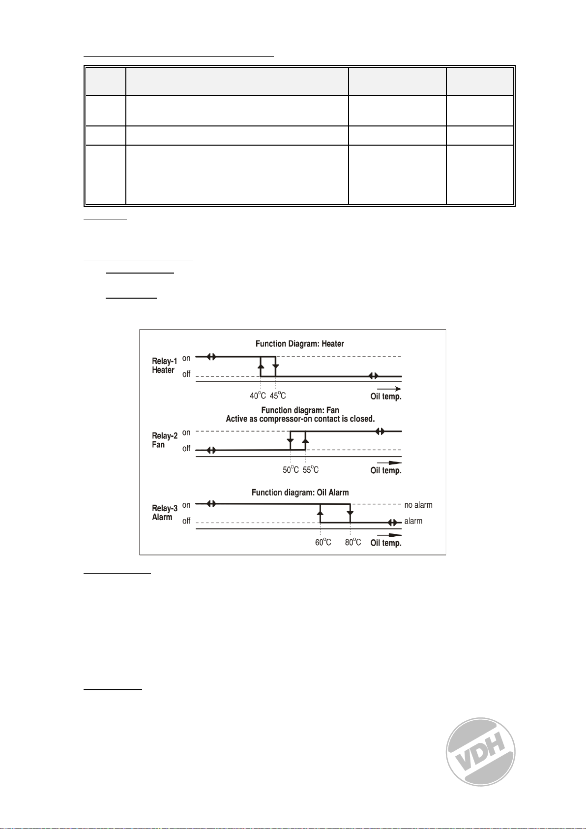
* Relay Functions.
The rel
ay-1 heater
temperature is above 45OC.
The relay-2 fan
above 55OC and it stops as the temperature drops below the 50OC or as the “compressor_
on” contact is opened.
activ
ates, as the oil temperature is below the 40OC and stops as the
acti
vates, as “compressor_on” contact is closed and the oil temperature is
Relay-3 alarm
deactivates (C-NC = closed). To reset an alarm push the UP key.
Oil-alarm [A0]: Alarm as the oil temperature is above 80OC and can be reset as
Cylinder temp.alarm: Alarm as an cylinder temperature is above the maximum cylinder
[A1...A12] temperature setting (P21), with a delay of 180 seconds or
* Address.
VDH
Products BV Tel: +31 (0)50 - 30 28 900
Produktieweg 1 Fax: +31 (0)50 - 30 28 980
9301 ZS Roden Email: info@vdhproducts.nl
The Netherlands Internet: www.vdhproducts.nl
is normal
ly active (C-NO = closed) and when a alarm occurs the relay alarm
the temperature drops below 60OC.
direct as an cylinder temperature is above maximum cylinder
temperature setting (P21) + 15K.
3
Page 4
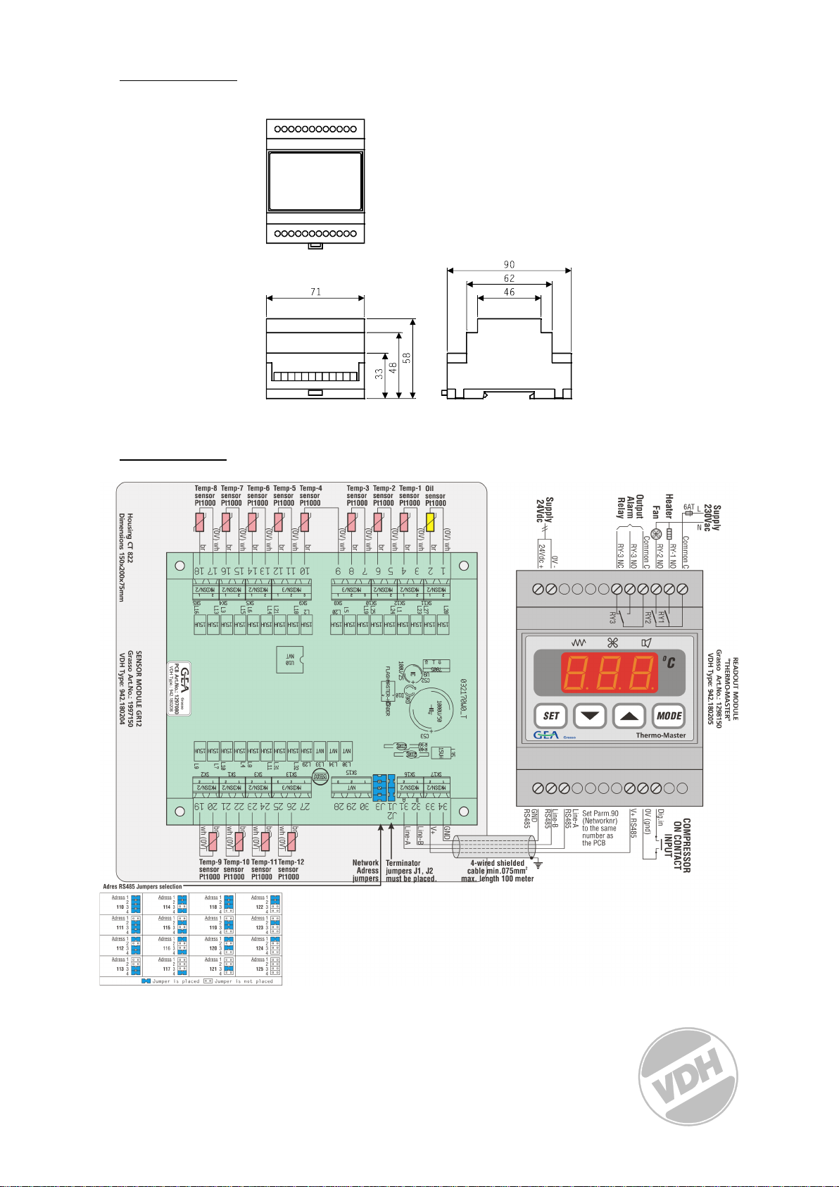
* Di
m
ensions.
* Conne
ctions.
4
Page 5

0087655 v005 Brugermanual
ALFA 53-Grasso Thermo-Master-kompressorenhed med PCB til
føler-input.
* Installation.
På tilslutningsdiagrammet til ALFA 53-Grasso kan du se, hvordan strømforsyningen, netværket (til følerpcb), kontakt-input og relæer skal tilsluttes.
Når ALFA 53-Grasso sluttes til strømforsyningen, startes en selvtest. Når testen er udført, vises den
målte olietemperatur i displayet.
* Kontrol.
Alarmtermostaten i ALFA 53-Grasso kan kontrolleres med fire trykknapper på forsiden
INDSTIL vis / ændr cylindertemperaturer.
OP forøg en værdi, og nulstil alarm.
NED formindsk en værdi.
TILSTAND vis status for relæer.
* Visning af cylindertemperaturer.
Ved tryk på knappen INDSTIL vælges den første cylindertemperaturføler, og ‘S1' vises i displayet for at
angive dette. Ved tryk på knappen TILSTAND vises følerens faktiske værdi i displayet.
Du kan vælge en anden cylindertemperatur ved at trykke på knappen OP og/eller NED. Displayet viser det
tilsvarende cylindertemperaturnummer f.eks. ‘S2', ‘S3'.
Nogle få sekunder efter slip af knapperne forsvinder cylindertemperaturen, og den målte olietemperatur
vises igen i displayet.
* Indstilling af interne parametre.
Foruden visning af cylindertemperaturer er visse interne indstillinger mulige som f.eks. antal cylindere og
maksimal cylindertemperatur.
Ved tryk på knappen NED i mere end 10 sekunder åbner du den 'interne programmeringsmenu'. I venstre
display blinker øverste og nederste segment. Over knapperne OP og NED kan den ønskede parameter
vælges (se parametertabel). Hvis den ønskede parameter vælges, kan værdien udlæses ved tryk på
knappen INDSTIL. Tryk på knappen OP og/eller NED giver dig mulighed for at ændre parameterens værdi.
Hvis der ikke trykkes på en knap i 20 sekunder, skifter ALFA 53-Grasso til normal driftstilstand.
0087655_04
2
* Fejlmeddelelser.
I displayet på ALFA 53-Grasso kan de følgende fejlmeddelelser blive vist:
Følerfejl, føleralarmer
E0 - Oliefølerfejl. A0 - Maksimal alarm i olieføler
E1 - Fejl i cylinderføler-1. A1 - Maksimal alarm i cylinderføler-1
..
..
E12- Fejl i cylinderføler-12. A14 - Maksimal alarm i cylinderføler-12
Generelle fejl
NC - Ingen netværkskommunikation Løsning: - Kontroller netværkskablet
Page 6

EE - Indstillinger er gået tabt. Løsning: Genprogrammer indstillingerne.
5HP on NH3; 143 deg. C
Løsning til følerfejl E0 ... E12:
- Kontroller, at føleren er tilsluttet korrekt.
- Kontroller føleren (1000 Ω ved 0º C).
- Udskift føleren.
Tryk på knappen OP for at nulstille en alarm.
* Tekniske detaljer.
Funktion : ALFA 53-Grasso Thermo-Master
Bestillingsnummer : 1298150 (Thermo-Master), 1997150
(følermodul GR12)
Interval : 0/+200º C, aflæsning pr. 1º C
Strømforsyning : 24 Vdc
Relæer : RY1 Heating SPST 250V/8A(NO), (cos phi=1)
RY2 Fan SPST 250V/8A(NO), (cos phi=1)
RY1 og RY2 har en fælles (C)
RY3 Alarm SPDT 250V/8A(C-NO-NC), (cos phi=1)
Kontrol : Trykknapper på forside.
Forside : Polykarbonat IP65
Input : Kompressor på kontakt-input (potentielt frit kontakt-input)
Følere : 13 x Pt1000 temperaturføler (1000 Ω ved 0º C) tilsluttet PCB
Netværk : RS485-netværk med strømforsyning (A,B,V+ og GND), afskærmet kabel med 4
ledninger til PCB
Mål : Controller 90 x 71 x 58 mm (hwd)
: PCB 120 x 105 mm (hw)
Nøjagtighed : ± 0,5 % i interval
- Leveres med hukommelsesbeskyttelse under strømsvigt.
- Tilslutning med skrueterminaler.
- Udstyret med selvtestfunktion og detektering af følerfejl.
* Parametre ALFA 53-Grasso.
PARAMETER BESKRIVELSE AF PARAMETER Interval STANDARDVÆRDI
20 Antal cylindere 0..12 8
21 Maksimal cylindertemperatur 100..185º C 155
90 Netværksnummer 110..125 110
95 Softwareversion 0..255 96 Produktionsår 00..99 97 Produktionsuge 1..52 98 Serienummer (x1000) 0..255 99 Serienummer (enheder) 0..999 -
Bemærkning: P90 skal indstilles til samme RS485-netværksnummer som på PCB (indstilles med
adressejumpere)
* Relæfunktioner.
Page 7

Relæ-1 i varmelegemet aktiveres, når olietemperaturen er under 40º C og stopper, når temperaturen er
over 45º C.
Relæ-2 i ventilatoren aktiveres, når kontakten "kompressor-til" lukkes, og olietemperaturen er over 55º C,
og den stopper, når temperaturen falder under 50º C, eller kontakten “kompressor-til” åbnes.
Function Diagram: Heater
Funktionsdiagram:
Varmelegeme
Relay-1 Heater Relæ-1, varmelegeme
On Til
Off Fra
40C 40º C
45C 45º C
Oil temp. Olietemp.
Function diagram: Fan Funktionsdiagram: Ventilator
Active as compressor-on contact is closed. Aktiv, da kontakten
kompressor-til er lukket.
Relay-2 Fan Relæ-2, ventilator
On Til
Off Fra
50C 50º C
55C 55º C
Oil temp. Olietemp.
Function diagram: Oil Alarm Funktionsdiagram: Oliealarm
Relay-3 Alarm Relæ-3, alarm
On Til
Off Fra
60C 60º C
80C 80►7C
Oil temp. Olietemp.
No alarm Ingen alarm
Alarm Alarm
Page 8

Alarm til relæ-3 er normalt aktiv (C-NO = lukket), og når en alarm indtræffer, deaktiveres relæalarmen (CNC = lukket). Tryk på knappen OP for at nulstille en alarm.
Oliealarm [A0]: Alarm, når olietemperaturen er over 80º C, og den kan nulstilles, når temperaturen falder
under 60º C.
Alarm for cylindertemperatur: Alarm, når rn cylindertemperatur er over cylinderens [A1...A12] maksimale
temperaturindstilling (P21) med en forsinkelse på 180 sekunder eller direkte, når en cylindertemperatur er
over cylinderens maksimale temperaturindstilling (P21) + 15K.
* Mål.
Page 9

* Tilslutninger.
Housing CT 822 Hus CT 822
Dimensions 150x200x75mm Mål 150 x 200 x 75 mm
SENSOR MODULE GR12
Grasso Art.No: 1997150
VDH Type: 942.180204
Temp-8 sensor Pt1000 Temp-8, føler Pt1000
Br Br
(OV) wh (OV) wh
Temp-7 sensor Pt1000 Temp-7, føler Pt1000
Br Br
(OV) wh (OV) wh
Temp-6 sensor Pt1000 Temp-6, føler Pt1000
Br Br
(OV) wh (OV) wh
Temp-5 sensor Pt1000 Temp-5, føler Pt1000
Br Br
(OV) wh (OV) wh
Temp-4 sensor Pt1000 Temp-4, føler Pt1000
Br Br
(OV) wh (OV) wh
Temp-3 sensor Pt1000 Temp-3, føler Pt1000
Br Br
(OV) wh (OV) wh
Temp-2 sensor Pt1000 Temp-2, føler Pt1000
FØLERMODUL GR12
Grasso bestillingsnummer: 1997150
VDH-type: 942.180204
Page 10

Br Br
(OV) wh (OV) wh
Temp-1 sensor Pt1000 Temp-1, føler Pt1000
Br Br
(OV) wh (OV) wh
Oil sensor Pt1000 Olieføler, Pt1000
Temp-1 sensor Pt1000 Temp-1, føler Pt1000
Br Br
(OV) wh (OV) wh
Temp-9 sensor Pt1000 Temp-9, føler Pt1000
Br Br
(OV) wh (OV) wh
Temp-10 sensor Pt1000 Temp-10, føler Pt1000
Br Br
(OV) wh (OV) wh
Temp-11 sensor Pt1000 Temp-11, føler Pt1000
Br Br
(OV) wh (OV) wh
Temp-12 sensor Pt1000 Temp-12, føler Pt1000
Br Br
(OV) wh (OV) wh
Network Adress jumpers Netværksadressejumpere
Terminator jumpers J1, J2 must be placed Terminatorjumpere J1, J2 skal være placeret
4-wired shielded cable min. 075mm2 max. length 100
meter
Line-A Linje-A
Line-B Linje-B
V+ V+
GND GND
Adres RS485 Jumpers selection Adresse RS485, jumpervalg
Supply 24 Vdc Strømforsyning 24 Vdc
24 Vdc+ 24 Vdc+
OV OV
Output alarm relay Output-alarmrelæ
Common C Fælles C
RY-3 NO RY-3 NO
RY-3 NC RY-3 NC
Heater fan Varmelegemeventilator
RY-2 NO RY-2 NO
RY-1 NO RY-1 NO
Supply 230 Vac Strømforsyning 230 Vac
6AT 6AT
L L
N N
Common C Alm. C
READOUT MODULE ‘THERMO-MASTER’Grasso Art.Nr.
1298150
VDH Type: 942.180205
GND
RS485
Line-B
RS485
Line-A
RS485
Set Parm.90 (Networknr.)to the same number as the PCB Indstil Parm.90 (netværksnummer) til samme nummer som
V+ RS485 V+ RS485
OV (gnd) OV (gnd)
Dig. in Indgang
COMPRESSOR ON CONTACT INPUT KONTAKT FOR KOMPRESSOR-TIL, INPUT
Adres 1 Adresse 1
Jumper is placed Jumper er placeret
Jumper is not placed Jumper er ikke placeret
Afskærmet kabel med 4 ledninger, min. 075 mm², maks.
længde 100 meter
UDLÆSNINGSMODUL ‘THERMO-MASTER’Grasso
bestillingsnummer 1298150
VDH-type: 942.180205
GND
RS485
Linje-B
RS485
Linje-A
RS485
på PCB
Page 11

Bedienungsanleitung
ALFA 53-Grasso Thermo-Master-PCB-input.
* Installation.
Am Anschlussbild des ALFA 53-Grasso ist erkentlich wie der Fühler, Versorgungsspannung und
Relaisangeschlossen werden. Wird der ALFA 53-Grasso mit Spannung versorgt, durchläuft er zuerst
einSelbsttestprogramm. Danach wird die gemessene Temperatur im Display angezeigt.
* Bedienung.
Mit Hilfe von vier Drucktasten wird der ALFA 53 bedient. Es handelt sich dabei um folgendeTasten:
SET - anschauen / verändern eingestellter Werte und Alarm reset.
▲(RAUF) - erhöhen eingestellter Werte.
▼(RUNTER) - absenken eingestellter Werte.
MODE - Relaisstatus Taste.
*Zylinder Temperaturen anzeigen
Durch Drücken der SET Taste wird der erste Zylinder Temperatur Sensor ausgewählt und S1 erscheint im Display.
Durch Drücken der Mode Taste wird der aktuelle Wert des Sensors im Display dargestellt.
Man kann durch Drücken der Rauf oder Runter Taste einen anderen Zylinder auswählen. Das Display zeigt die
entsprechende Zylinder Temperatur Nummer (S2, S3 ...) an.
En paar Sekunden nach dem Drücken der Tasten verschwindet die Zylinder Temperatur und die gemessene Öl
Temperatur wird wieder im Display angezeigt.
Page 12

*Fehlermeldungen
-
-
-
-
-
-
-
-
-
-
-
-
-
5HP on NH3; 143 deg. C
Im Display des ALFA 53-Grasso können folgende Fehlermeldungen erscheinen:
Sensor Fehler
E0
E1
E2
E3
E4
E5
E6
E7
E8
E9
E10
E11
E12
Allgemeine Fehler
NC - Keine Netzwerkverbindung Behebung:-Netzwerkkabel überprüfen
EE - keine Einstellungen vorhanden Behebung:-Einstellungen neu programmieren
Behebung der Sensor Fehler E0…E12
Sensor Alarme
- Öl Sensor Fehler
- Zylinder Sensor 1 Fehler
- Zylinder Sensor 2 Fehler
- Zylinder Sensor 3 Fehler
- Zylinder Sensor 4 Fehler
- Zylinder Sensor 5 Fehler
- Zylinder Sensor 6 Fehler
- Zylinder Sensor 7 Fehler
- Zylinder Sensor 8 Fehler
- Zylinder Sensor 9 Fehler
- Zylinder Sensor 10 Fehler
- Zylinder Sensor 11 Fehler
- Zylinder Sensor 12 Fehler
A0
A1
A2
A3
A4
A5
A6
A7
A8
A9
A10
A11
A12
Maximum Alarm Öl Sensor
Maximum Alarm Zylinder Sensor 1
Maximum Alarm Zylinder Sensor 1
Maximum Alarm Zylinder Sensor 1
Maximum Alarm Zylinder Sensor 1
Maximum Alarm Zylinder Sensor 1
Maximum Alarm Zylinder Sensor 1
Maximum Alarm Zylinder Sensor 1
Maximum Alarm Zylinder Sensor 1
Maximum Alarm Zylinder Sensor 1
Maximum Alarm Zylinder Sensor 1
Maximum Alarm Zylinder Sensor 1
Maximum Alarm Zylinder Sensor 1
‐ ÜberprüfungoberSensorkorrektangeschlossenist
‐ Sensorüberprüfen(1000Ωbei0°C)
‐ Sensorerstzen
Zum Zurücksetzen eines Alarms muss die Rauf Taste gedrückt werden.
* Technische Daten.
Type : ALFA 53-Grasso Alarmthermostat
Bereich : -50/+50,0°C, über -10°C Anzeige in 0,1°C
Versorgung : 230Vac 50/60Hz (-5/+10%)
Anzeige : 3-ziffriges 7-Segment
DisplayRelais : Ry1= SPST(NO)250V/8A (cos φ=1) of 250V/5A (cos φ=0.4)
Ry2= SPST(NO)250V/8A (cos φ=1) of 250V/5A (cos φ=0.4)
Ry3= SPDT(NO/NC)250V/8A (cos φ=1) of 250V/5A (cos φ=0.4)
Relais haben einen Gemeinsamen (C).
Bedienung : über Drucktasten auf der Front.
Front : PolycarbonatFühler: 1x SM 811/2m (PTC 1000Ω bei 25°C).
Abmessungen : 90 x 71 x 58mm (HBT)
Einbaumaße : 46 x 71mm (HB) bei Front einbau
Genauigkeit : ± 0,5% des Bereichs.
- Eingebaute Datensicherung bei Spannungsausfall.
- Anschluss über Schraubklemmen an Ober- und Unterseite.
- Ausgestattet mit Selbsttestfunktion und Anzeige bei Fühlerstörung.
* Parameter ALFA 53-Grasso.
PARAMETER
20
21
Beschreibung Parameter
Anzahl Zylinder
Maximale Zylinder Temperatur
RANGE STANDARD VALUE
0..12 8
100..185º C 155 oC resp.
143
o
C 5HP/NH3
Page 13

90
95
96
97
98
99
Netzwerk Nummer
Softwareversion
Produktionsjahr
Produktionswoche
Seriennummer (x1000)
Seriennummer (Einheiten)
110..125 110
0..255 -
00..99 -
1..52 -
0..255 -
0..999 -
Bemerkung: Bemerkung: P90 muss auf dieselbe RS485 Netzwerk Nummer wie auf den PCB (Einstellung durch
die Adressen Brücke) gesetzt werden.
*Relais Funktionen
Der Relais-1 Heizung springt an, wenn die Öltemperatur unter 40°C gefallen ist und stoppt, wenn die Temperatur
über 45°C ist.
Der Relais-2 Lüfter springt an, wenn der „compressor_on“ Kontakt geschlossen und die Öltemperatur über 55°C ist
und stoppt, wenn die Temperatur unter 50°C gefallen ist oder wenn der der „compressor_on“ Kontakt geöffnet
ist.
Der Relais-3 Alarm ist in der Regel aktiv (C-NO=ge
deaktiviert (C-NC=geschlossen). Zum Zurücksetzen eines Alarms muss die Rauf Taste gedrückt werden.
Öl-Alarm [A0]: Dieser Alarm wird aktiv, wenn die Temperatur größer als 80°C ist und kann erst wieder
zurückgesetzt werden wenn die Temperatur unter 60°C fällt.
Zylinder Temp. Alarm [A1..A12]: Dieser Alarm wird mit einer Verzögerung von 180 Sekunden aktiv, wenn
eine Zylinder Temperatur größer als die maximale Zylinder Temperatur
(Parameter 21) ist oder er wird direkt aktiv, wenn eine Zylinder
Temperatur um mehr als 15 Kelvin größer als die maximale Zylinder
Temperatur (Parameter 21) ist.
schlossen) und wenn ein Alarm eintrifft, wird der Relais Alarm
Page 14

Begriffe Bild:
Function Diagram: Heater — Funktionsdiagramm Heizung
Relay-1 Heater- Relais-1 Heizung
Function diagram: Fan — Funktionsdiagramm Lüfter
Active as Compressor-on contact is closed- Aktiv, wenn der “compressor_on” Kontakt geschlossen ist.
Relay-2 Fan- Relais-2 Lüfter
Relay-3 Alarm- Relais-3 Alarm
Function diagram: Oil alarm — Funktionsdiagramm Öl Alarm
No alarm- kein Alarm
Oil temp. — Öl Temp.
Page 15

* Abmessungen.
Page 16

* Anschlussdaten.
 Loading...