


Artisan Technology Group is your source for quality
new and certied-used/pre-owned equipment
• FAST SHIPPING AND
DELIVERY
• TENS OF THOUSANDS OF
IN-STOCK ITEMS
• EQUIPMENT DEMOS
• HUNDREDS OF
MANUFACTURERS
SUPPORTED
• LEASING/MONTHLY
RENTALS
• ITAR CERTIFIED
SECURE ASSET SOLUTIONS
SERVICE CENTER REPAIRS
Experienced engineers and technicians on staff
at our full-service, in-house repair center
Instra
Remotely inspect equipment before purchasing with
our interactive website at www.instraview.com
Contact us: (888) 88-SOURCE | sales@artisantg.com | www.artisantg.com
SM
REMOTE INSPECTION
View
WE BUY USED EQUIPMENT
Sell your excess, underutilized, and idle used equipment
We also offer credit for buy-backs and trade-ins
www.artisantg.com/WeBuyEquipment
LOOKING FOR MORE INFORMATION?
Visit us on the web at www.artisantg.com for more
information on price quotations, drivers, technical
specications, manuals, and documentation
7177 N. Atlantic Avenue, Cape Canaveral, Florida 32920-3719 USA
MARQUEE™ 8521 Ultra Green (HUD)
User’s Manual
VDCDS P/N: 71180-01 / Revision 1.0 / July 2003
Section 1
Section 2
Specifications / Dimensions
Installation & Setup
Section 3
Section 4
Appendix A
Appendix B
Appendix C
Operation
Maintenance
Menu Tree
Marquee Projectors RS-232 Control
Glossary
Artisan Technology Group - Quality Instrumentation ... Guaranteed | (888) 88-SOURCE | www.artisantg.com

This Page Intentionally Left Blank
Artisan Technology Group - Quality Instrumentation ... Guaranteed | (888) 88-SOURCE | www.artisantg.com

Table of Contents
Table of Contents
Section 1 Specifications / Dimensions....................................................................................................1-1
1.1 8521 Ultra Green (HUD) Specifications........................................................................................1-1
1.2 Electronic Chassis Main Assemblies and Dimensions .................................................................1-2
1.3 CRT Head Main Assemblies and Dimensions..............................................................................1-3
Section 2 Installation & Setup................................................................................................................. 2-1
2.1 Quick Setup................................................................................................................................... 2-1
2.2 Keypad Operating Settings ...........................................................................................................2-1
2.2.1 IR Remote Battery Replacement......................................................................................2-2
2.2.2 Remote Control Conversion or Protocol Setting Change.................................................2-2
2.3 Source Connections......................................................................................................................2-3
2.4 Serial Port Connections ................................................................................................................2-4
2.5 Optical Alignment ..........................................................................................................................2-5
2.6 Source Setup ................................................................................................................................2-6
2.7 Memory Setup...............................................................................................................................2-8
2.7.1 About Setup Memories ..................................................................................................... 2-8
2.7.2 About ASI and ASR ..........................................................................................................2-9
2.7.3 Input Memory Setup .........................................................................................................2-9
2.7.4 Recall Memory Setup .......................................................................................................2-9
2.7.5 ASI Improvement ............................................................................................................2-10
2.7.6 ASI with Save Logic Diagram ......................................................................................... 2-11
2.7.7 ASR Setup ...................................................................................................................... 2-12
Section 3 Operation ................................................................................................................................3-1
3.1 Overview ....................................................................................................................................... 3-1
3.1.1 Projector Basics................................................................................................................3-1
3.1.2 Keypads............................................................................................................................3-1
3.1.3 IR Remote Keypad ...........................................................................................................3-1
3.1.4 Wired Remote Keypad......................................................................................................3-1
3.1.5 Presenter's Keypad (optional) ..........................................................................................3-1
3.1.6 Keypad Usage ..................................................................................................................3-3
3.1.7 Slidebars...........................................................................................................................3-3
3.1.8 Menus ............................................................................................................................... 3-4
3.1.9 Dialog Boxes..................................................................................................................... 3-4
3.1.10 Message Boxes ..............................................................................................................3-4
3.1.11 Help Pages .....................................................................................................................3-4
3.1.12 Test Patterns ..................................................................................................................3-4
3.1.13 Using Help ......................................................................................................................3-5
Display Systems
Artisan Technology Group - Quality Instrumentation ... Guaranteed | (888) 88-SOURCE | www.artisantg.com
i

Marquee 8521 Ultra Green (HUD) User's Manual
3.1.14 Power-on.........................................................................................................................3-6
3.1.15 Standby Mode................................................................................................................. 3-6
3.1.16 Audio Functions .............................................................................................................. 3-6
3.1.17 System Status Pages .....................................................................................................3-7
3.2 Source Selection ...........................................................................................................................3-8
3.2.1 Input Selection ..................................................................................................................3-8
3.3 Setup Memories ..........................................................................................................................3-10
3.3.1 Memories ........................................................................................................................3-10
3.3.2 Input Memories ...............................................................................................................3-11
3.3.3 Recall Memories ............................................................................................................. 3-11
3.3.4 Memory Allocation ..........................................................................................................3-11
3.3.5 Locking Setup Memories ....................................................................................3-11
3.4 Display Adjustments....................................................................................................................3-12
3.4.1 Primary Display Adjustments..........................................................................................3-12
3.4.2 Picture Functions ............................................................................................................ 3-13
3.4.3 Geometry Functions [GEOM] .........................................................................................3-14
3.5 Convergence Registration...........................................................................................................3-16
3.5.1 Green Interpolated..........................................................................................................3-17
3.5.2 Green Random Access................................................................................................... 3-17
3.6 Utility Features ............................................................................................................................3-18
3.6.1 Source Setup [UTIL] [1] ..................................................................................................3-18
3.6.2 Remote Control Options [UTIL] [6] .................................................................................3-23
3.7 Multi-projector Functions.............................................................................................................3-27
3.7.1 The Projector ..................................................................................................................3-27
Section 4 Maintenance ...........................................................................................................................4-1
4.1 Warnings and Guidelines ..............................................................................................................4-1
4.1.1 Labels and Markings.........................................................................................................4-1
4.1.2 Projector Location.............................................................................................................4-1
4.1.3 Power Cord and Attachments........................................................................................... 4-1
4.1.4 Ventilation Slots ................................................................................................................4-1
4.1.5 Servicing ........................................................................................................................... 4-2
4.2 Cleaning ........................................................................................................................................ 4-2
4.2.1 Lens Cleaning...................................................................................................................4-2
4.2.2 Case Cleaning ..................................................................................................................4-2
4.3 Trouble-shooting ...........................................................................................................................4-2
4.3.1 Projector Response Problems ..........................................................................................4-3
Appendix A Menu Tree .......................................................................................................................... A-1
ii Table of Contents
Artisan Technology Group - Quality Instrumentation ... Guaranteed | (888) 88-SOURCE | www.artisantg.com

Marquee 8521 Ultra Green (HUD) User's Manual
Appendix B Marquee Projectors RS-232 Control...................................................................................B-1
B.1 Brief History of Marquee RS-232 Communications ......................................................................B-1
B.2 System Requirements and Setup .................................................................................................B-1
B.3 RS-232 Communication Cables....................................................................................................B-2
B.3.1 RS-232, 9-Pin Male to 9-Pin Female ...............................................................................B-2
B.3.2 RS-232, 9-Pin Male to 25 Pin Female..............................................................................B-2
B.4 Data Transmission Structure ........................................................................................................B-3
B.5 Transport Layer.............................................................................................................................B-3
B.5.1 $01 AND $0E (MESSAGE START AND END)................................................................B-4
B.5.2 $13 AND $11 (STOP AND RESUME) .............................................................................B-4
B.5.3 $1B (ESCAPE) .................................................................................................................B-4
B.6 Message Format ...........................................................................................................................B-4
B.6.1 HEADER (NETWORK/PROJECTOR ADDRESSING) ....................................................B-4
B.6.2 BODY ...............................................................................................................................B-5
B.6.3 Optional Checksum ..........................................................................................................B-6
B.6.4 Command Codes .............................................................................................................B-6
B.7 Creating Simple Messages ........................................................................................................B-10
B.7.1 Sample Data Transmissions ......................................................................................... B-11
B.7.2 “Standby” Command ..................................................................................................... B-13
B.7.3 “Picture Mute” Command .............................................................................................. B-13
B.7.4 “Projector Address” Command...................................................................................... B-14
B.7.5 “Signal Status” Command ............................................................................................. B-14
B.7.6 “Ping” Command ........................................................................................................... B-15
B.7.7 “Test Pattern” Diagnostic Command............................................................................. B-15
B.7.8 Color Modulation (CNM) Command.............................................................................. B-16
B.7.9 Color Temperature Modify Command (CTM)................................................................ B-17
Appendix C Glossary ............................................................................................................................. C-1
Display Systems
Artisan Technology Group - Quality Instrumentation ... Guaranteed | (888) 88-SOURCE | www.artisantg.com
iii

Marquee 8521 Ultra Green (HUD) User's Manual
List of Figures
Figure 2-1. Remote Control Battery Replacement..................................................................................................2-2
Figure 2-2 Remote Control Jumper Settings ..........................................................................................................2-2
Figure 2-3. Power Connection ................................................................................................................................2-3
Figure 2-4. Built-in RGB Interface Connections (Video Input Module-VIM) ...........................................................2-3
Figure 2-5. Serial Port Connections........................................................................................................................2-4
Figure 2-6. 8521 Lens Assembly ............................................................................................................................2-5
Figure 3-1. Full Function Keypad...........................................................................................................................3-2
Figure 3-2. Test Patterns and Selection .................................................................................................................3-4
Figure 3-3. Rear Panel LEDs..................................................................................................................................3-6
Figure 3-4. System Status Pages ...........................................................................................................................3-7
Figure 3-5. Projector Slots .....................................................................................................................................3-8
Figure 3-6. Independent IR Keypad Control ........................................................................................................3-24
Figure 4-1. Rear Panel LEDs..................................................................................................................................4-2
Figure B-1. Cable Wiring, RS-232, 9-Pin Male to 25-Pin Female.......................................................................... B-2
Figure B-2. A Complete RS-232 Data Transmission ............................................................................................. B-3
Figure B-3. Format of Address Field...................................................................................................................... B-5
Figure B-4. The “set contrast to 64” command .................................................................................................... B-10
Figure B-5. Ping Reply Contents.......................................................................................................................... B-15
List of Tables
Table 3-1. Type Field Events ................................................................................................................................3-26
Table 3-2. Interval Field Options...........................................................................................................................3-26
Table B-1. Transport Layer Special Control Codes ............................................................................................... B-3
Table B-2. Network Address Assignments ............................................................................................................ B-5
Table B-3. Command Codes and Descriptions...................................................................................................... B-7
Table B-4. RS-232 Commands in v.4.0 ............................................................................................................... B-11
Table B-5. Sync Replies....................................................................................................................................... B-15
Table B-6. Color Modulation (CNM) Command................................................................................................... B-16
Table B-7. Color Temperature Command (CTM) ................................................................................................ B-17
iv Table of Contents
Artisan Technology Group - Quality Instrumentation ... Guaranteed | (888) 88-SOURCE | www.artisantg.com

Section 1 Specifications / Dimensions
The Marquee 8521 Ultra Green (HUD) Series projectors utilize 8” high brightness, electromagnetic focus, high
resolution CRTs. There are many applications which demand image quality that can only come from unpixelized
CRT projection systems. The Marquee Ultra HUD meets these demands by providing consistently bright, high
resolution images with true black levels and geometry distortion. When the ultimate in displays is required, call on
VDCDS Marquee Ultra Series projectors to fulfill your requirements.
1.1 8521 Ultra Green (HUD) Specifications
VDCDS P/N: 69876-01
Optics
• High definition, low magnification F3.3 lens
• 6 line pairs per mm (lp/mm) resolution / 8 lp/mm at short conjugate
• Marquee Ultra electromagnetic focus CRTs
• Throw Ratio: 4.37:1
Resolution
• 2500x2000 addressability
• 1600x1200 ANSI pixels
Brightness
• 115 lumens
Cable Length
• The optics head of the projector is separated from the base electronics by a
standard 6 ft (1.8 m) connection cable. For installations requiring extended
range, there are options for up to 25 ft. (7.6 m) cable length.
ASR/ASI
• The projector will automatically update all parameters, including
convergence contrast, brightness, keystone, phase, etc., when a new
source is detected. The set-up is taken from a matching memory or
interpolated from two adjacent memories.
Video Circuits
• 0.5 to 1.0 volts p-p, 75 ohms +/-1 % terminated
• Circuitry for improved video performance and gray-scale tracking
• 150 MHz bandwidth (-3dB); (accommodates 3 nanosecond pixels and
digital dock rates over 300 MHz),
• Keyed clamp, better than 1 % accuracy
Sync and Deflection Circuits
• Input level: 0.3 to 5.0 volts pp., 75 ohms terminated
Geometry
• Rectilinear accuracy: 1.0 % maximum of picture height
• Horizontal Linearity: 2.0 % maximum
• Vertical Linearity: 1.0% maximum
• Top and bottom keystone control
• Vertical and horizontal skew control
• Vertical and horizontal bow control
• Special Extended Geometry Distortion Option available
Power Requirements
• 90 VAC to 264 VAC universal input
• Power 500 watts maximum (approx.)
• Line frequency 50 to 60 Hz nominal
• Power factor corrected
Control Features
• Multi-language software (user selectable)
• Built-in set-up tutorials
• 5 built-in test patterns
• Programmable Events and Real Time Clock
• Menu driven interface with on-screen help
• Auto power-up after interruption
• Internal frequency generator
Scope of Supply
• Optics head: 1 Green CRT and lens
• 6’ electronic cable with connectors (standard)
• Electronics base unit
• 2 fully functional programmable remote IR keypads.
• Users manual
• 10' AC line cord
• Tool Kit
Display
• Electronic geometry circuits separately correct top, bottom and sides of
displayed image
• Color temperature adjustment for precise set-up
• S&C vertical and horizontal linearity
• Top, bottom, and side blanking
• Keystone circuitry to correct pictures angles up to ± 15° vertically from
screen axis
• Scheimpflug adjustment for top, bottom and side to side focus
• Marquee Ultra has 9 zone electronic astigmatism correction and 8 zone
contrast modulation control
• Automatically switches to separate Sync, composite sync or sync on green.
Separate Sync and composite sync is automatically accepted in either
polarity. (Sync on green limited to 180 Hz
• Smartlock™ processing circuitry for quick lock-in and ultra steady images
Vertical Deflection
• Frequency range: 39.5 Hz to 185 Hz. Size automatically regulated over
frequency range and electronically adjustable over a 115 % range. Retrace
time: less than 300 microseconds
Horizontal Deflection
• Frequency range:: 15 kHz to 152 kHz
• Size automatically regulated over frequency range. Retrace time compatible
with signals having horizontal blanking times below 1.5 microseconds
Inputs/Outputs
• Built-in RGB input. Optional input modules can install in interface slot
• Built-in RS232 for computer control, with loop through for connection of
multiple projectors
Contrast Modulation
• This feature adjusts the brightness in single or multiple zones for improved
color and brightness uniformity. Standard on all Marquee Ultra models
Maximum Operating
• Temperature: 0° to 35" (32" to 95°F)
• Altitude. 0 to 3000 m (0 to 10,000 ft)
• Heat Dissipation. 2450 BTU/HR (approx.)
• Humidity: 0 to 90 % non-condensing
• Storage Temperature: -30° to 65"C (-22" to 149"F)
Weight
• Marquee Ultra HUD Series:
o Electronic Chassis: 60 lbs. (27 kg)
o CRT Head Assembly: 75 lbs. (34 kg)
Regulatory Approvals
• Meets FCC Class A, DHHS and HWC plus CSA / UL / EN 60 950
requirements
• EN55022 Class B and EU directives 73/23/EEC, 89/336/EEC (CE marked)
Due to constant research and development, product specifications
are subject to change without prior notice.
Display Systems
1-1
Artisan Technology Group - Quality Instrumentation ... Guaranteed | (888) 88-SOURCE | www.artisantg.com
Marquee 8521 Ultra Green (HUD) User's Manual
R
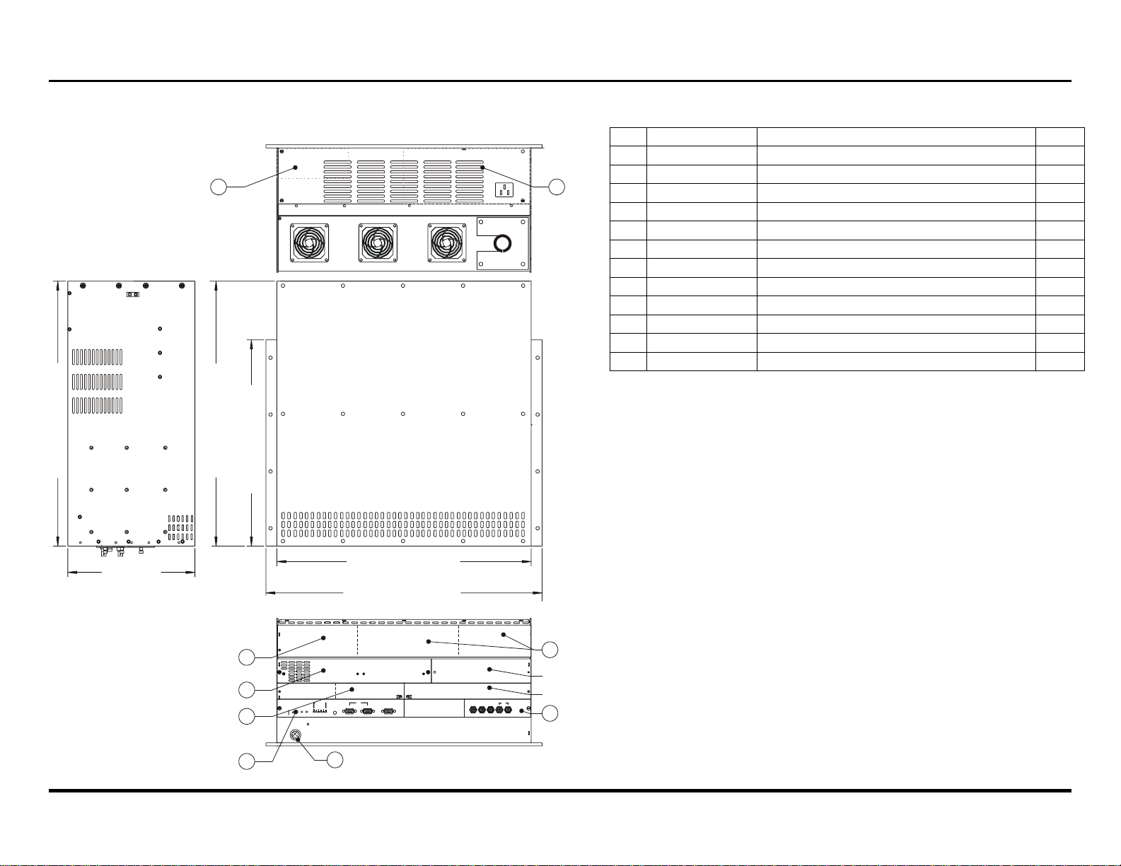
1.2 Electronic Chassis Main Assemblies and Dimensions
ear View
8 9
Side View
22.0 in. [56 cm]
22.0 in. [56 cm]
17.1 in [43 cm]
Top View
VDCDS P/N DESCRIPTION QTY
#
1 03-280336-07P Control/DPB/Stig-Waveform 1
2 81722-01 Marquee Contrast Modulation 1
3 03-270354-04P Module Focus & Geometry 1
4 03-271330-02P Stigmator Module 1
5 03-270350-01P Convergence Amp/Vertical Deflection Module 1
6 03-270335-05P Video Input Module 1
7 03-000250-02P IR Sensor 1
8 03-000310-02P HVPS 1
9 03-000229-05P LVPS 1
Ref 81721-01 Conv/Stig/Vert Adaptor, PCB 1
Ref 81730-01 HUD Mother Board, Elec. Chassis 1
Ref 81741-01 Vertical Load 2
10.6 in.
[27 cm]
4
21.2 in. [54 cm]
23.0 in. [58 cm]
5
Blank
3
ERROR
POWER
RESET
2
STANDBY
1
RS-232
DIAGNOSTICS
EHT
V FAIL
H FAIL
CLVPS
REMOTE
7
SWITCHER
IN OUT
Front View
HOR/COMPRED GREEN BLUE VERT
Blank
SYNC
6
1-2 Specifications / Dimensions
Artisan Technology Group - Quality Instrumentation ... Guaranteed | (888) 88-SOURCE | www.artisantg.com
Section 2
W
S
W
W
2
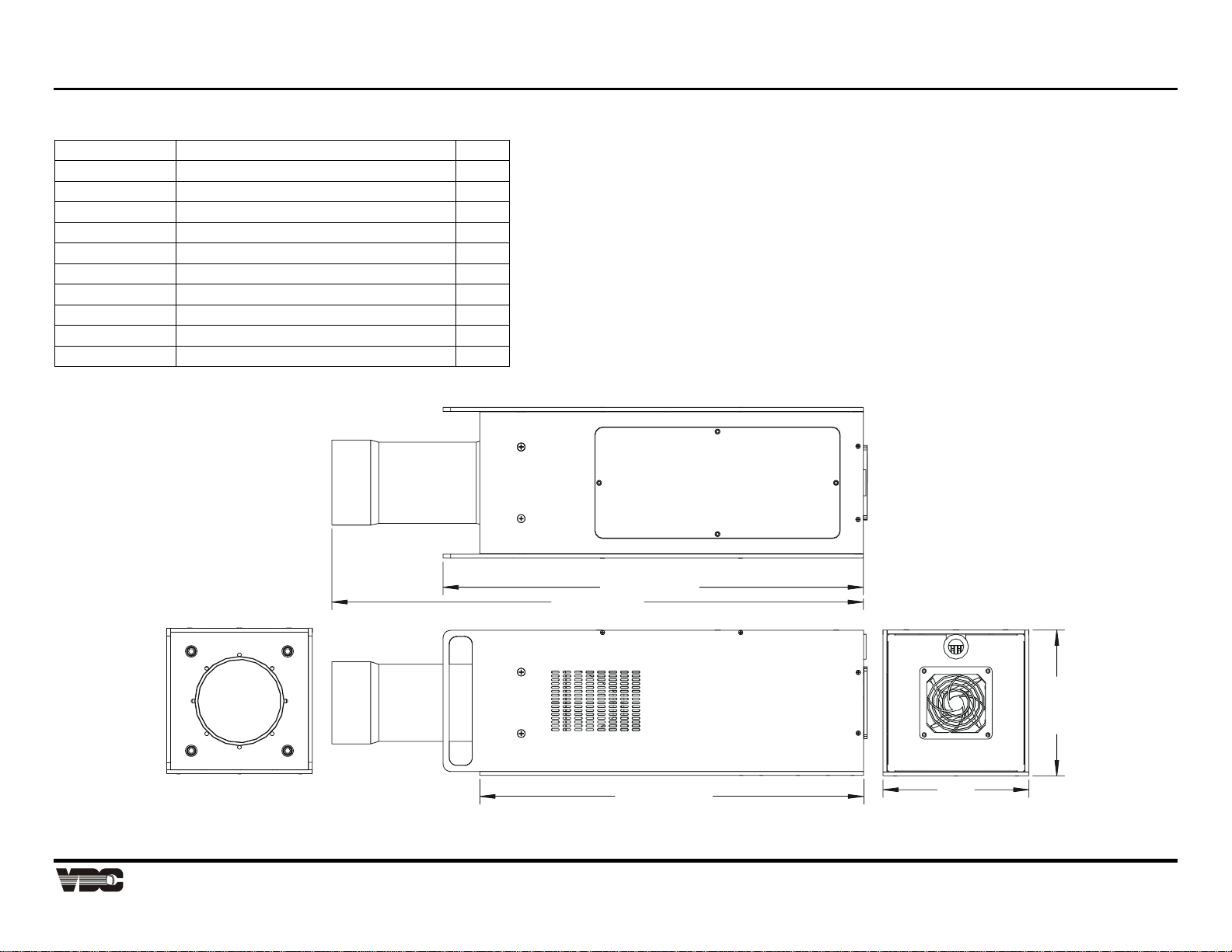
1.3 CRT Head Main Assemblies and Dimensions
VDCDS P/N DESCRIPTION QTY
03-007062-03P CRT 8" MAG FOCUS GRN PANASONIC 1
03-270338-02P VIDEO NECK MODULE 8520/8521 1
21-000687-04 STIGMATOR RING 1
21-000691-01 YOKE DEFLECTION 8" 1
21-000692-01 COIL, CONVERGENCE 8" 1
21-000695-01 FOCUS MAG WITH STIGMATOR 8" 1
59874-01 SPLITTER, 1 IN, 1 OUT 1
59879-01 LENS, LOW MAG, HUD 1
81731-01 HUD MOTHER BD, HEAD 1
81732-01 HUD HORIZ. DEFLECTION MODULE 1
TOP VIE
27.4 in [70 cm]
34.6 in [88 cm]
4 cm]
9.5 in.
[
25.0 in. [64 cm]
FRONT VIEW
Display Systems
1-3
Artisan Technology Group - Quality Instrumentation ... Guaranteed | (888) 88-SOURCE | www.artisantg.com
DIE VIE
9.5 in.
[24 cm]
REAR VIE

Marquee 8521 Ultra Green (HUD) User's Manual
This Page Intentionally Left Blank
1-4 Specifications / Dimensions
Artisan Technology Group - Quality Instrumentation ... Guaranteed | (888) 88-SOURCE | www.artisantg.com

Section 2 Installation & Setup
This section explains how to install and set up the projector. If you are familiar with the projector and want to
quickly set it up for temporary use, follow the Quick Setup instructions in Section 2.1. For a complete setup, skip
Section 2.1 and follow the instructions and guides covered in the remaining subsections.
2.1 Quick Setup
Follow these 7 steps for quick set up of the projector:
Step 1. Position the Projector
To perform a quick setup, the projector must be positioned so that the throw distance is the same
as that used during the most recent optical alignment; otherwise a detailed setup is required. The
throw distance is the distance between the center lens on the projector and the center of the
projection screen.
Note: If an optical lens alignment is required, refer to Section 2.5, Optical Alignment.
Step 2. Connect the Power Cord
Plug the AC line cord into the line input unit on the electronic chassis. Plug the three prong end
of the line cord in a grounded AC outlet.
Note: Input voltage must be between 90 VAC and 264 VAC.
Note: Ensure the line cord is the proper type for the AC receptacle.
Step 3. Connect a Source
Connect a source to the projector's built-in RGB input (slot 1). Ensure the source is on and
properly connected.
Step 4. Turn the Projector On
Press [POWER] on the keypad to turn the projector on. Hold down the power key for about one
second.
Note: If the keypad has been configured for IR remote operation, point it towards the screen or the front of
the electronic chassis.
Step 5. Select the Input
Press [SOURCE] [0] [1] to select the source connected to the built-in RGB input. Or, if installed
with the optional image shift, press [SOURCE] [0] [2] to select the source connected to the Image
Shifter input.
Step 6. Adjust the Display
Press [HELP] [1] to select the Guided Source Setup tutorial.
2.2 Keypad Operating Settings
The keypad includes its own memory to store keypad operating settings. With a few simple keystrokes you can
over-ride the "hard wire" protocol setting (explained earlier) and enable or disable the backlit feature. Keypad
battery life is increased if the backlit feature is disabled. The new operating settings are stored in the keypad until
the batteries are replaced (IR remote keypad) or the keypad connection cable is unplugged (wired).
If the keypad is configured for IR remote operation, make sure the batteries are installed. If it is configured for
wired remote operation, make sure its extension cable is properly connected to the projector. Perform the
following keystroke sequences to change its operating settings:
• To toggle the keypad's protocol setting (A or B), press [] [BRITE] [TINT] [DETAIL] [ 1 ].
• To toggle the backlit feature (enable or disable), press [] [BRITE] [TINT] [DETAIL] [ 3 ].
• To return all configuration settings to the jumper settings, press [] [BRITE] [TINT] [DETAIL] [ 0 ].
Note: The projector will not respond to keypad commands if you press [] [BRITE] [TINT] [DETAIL] [ 2 ]. If
pressed accidentally, press [] [BRITE] [TINT] [DETAIL] [ 0 ] to clear all keystroke settings.
2-1
Artisan Technology Group - Quality Instrumentation ... Guaranteed | (888) 88-SOURCE | www.artisantg.com
Marquee 8521 Ultra Green (HUD) User's Manual
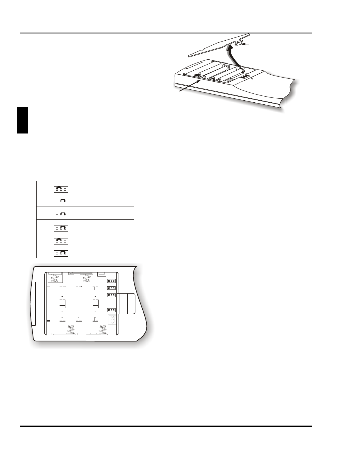
2.2.1 IR Remote Battery Replacement
Locate the battery compartment at the back side of the
keypad. Squeeze the latch to open the door. Replace
the batteries. For an IR remote keypad, place four AA
size, 1.5V alkaline batteries in the compartment
ensuring that the +/- orientation of each battery is
correct. Position the compartment door into place.
Latch
Battery
Compartment
WARNING: DO NOT INSTALL BATTERIES IN
THE KEYPAD IF A BUILT-IN OR WIRED
!
REMOTE CABLE IS ATTACHED TO IT. THIS
MAY CAUSE THE BATTERIES TO EXPLODE.
Figure 2-1. Remote Control Battery Replacement
2.2.2 Remote Control Conversion or Protocol Setting Change
If converting the keypad to an IR remote or changing protocol, unplug the cable connector. Locate the jumper
wires next to the cable connector location. The jumper wires control the keypad's operating settings.
JP1
JP2
JP3
JP4
321
PROTOCOL A
321
PROTOCOL B
321
(ALWAYS)
321
(ALWAYS)
321
BUILT-IN OR
WIRED KEYPAD
321
IR REMOTE KEYPAD
JP1: This jumper setting is important if the keypad is
configured for remote operation. There are two keypad
protocols: A and B. These protocols are available to
allow two projectors in the same room to be
independently controlled by separate remote keypads.
The protocol setting of the keypad must match that set in
the projector's Keypad Options menu ([UTIL] [6] [1]).
For more information about keypad protocols, refer to
the Remote Control Options entry in Section 3.6, Utility
Features.
JP2: This jumper must always be set between pins 1
and 2 as shown; otherwise, the projector will not respond
correctly to keypad commands.
JP1
JP2
JP3
JP4
321
321
321
321
JP3: This jumper must always be set between pins 1
and 2 as shown; otherwise, the backlit feature will be
disabled and the projector will not respond correctly to
keypad commands.
JP4: The JP4 jumper setting sets the keypad type. If
you are converting the keypad to an IR remote, move
the JP4 jumper from between pins 2 and 3 to pins 1 and
2.Power Connection
Figure 2-2 Remote Control Jumper Settings
2-2 Installation & Setup
Artisan Technology Group - Quality Instrumentation ... Guaranteed | (888) 88-SOURCE | www.artisantg.com

Section 2
50
z
S
e
(Op
2.3 Source Connections
To apply power to the projector, plug the AC line cord
into the line input socket located at the front panel of
the projector. Plug the three prong end of the line cord
in a grounded AC outlet. Input voltage to the projector
must be between 90 and 264 VAC, 50 or 60 Hz. The
power source must supply 650 watts of power to the
projector.
100 - 240 VAC
- 60 H
Rear View
Figure 2-3. Power Connection
The projector includes a built-in RGB input interface (Video Input Module) for connection of external RGB
sources. This input interface is shown in Figure 2-4 The built-in interface is required for normal operation.
The standard and optional RGB interfaces provide connection of an RGB source having one of the following sync
types: sync on green (3-wire), composite sync (4-wire), or separate H & V sync (5-wire). To connect a source,
connect the red, green, and blue outputs to the RED, GREEN, and BLUE inputs on the interface. If the source
uses sync on green, no additional cables are required. If the source provides a composite sync output, connect it
to the HOR/COMP input. If the source provides separate horizontal and vertical sync outputs, connect the
horizontal sync signal to the HOR/COMP input, and connect the vertical sync input to the VERT input.
Interconnection cables must be terminated with BNC connectors. Figure 2-4 show source connections for the
built-in interface.
DIAGNOSTICS
ERROR
POWER
RESET
STANDBY
RS-232
SWITCHER
IN OUT
EHT
V FAIL
H FAIL
CLVPS
REMOTE
HOR/COMPRED GREEN BLUE VERT
SYNC
Slot 2
tional) Slot 1
Video Input Module
(RGB Interface)
SYNC
GREENRED BLUE HOR/COMP VERT
BNC
connectors
RGB and Sync
Signals from
ourc
Figure 2-4. Built-in RGB Interface Connections (Video Input Module-VIM)
Display Systems
Artisan Technology Group - Quality Instrumentation ... Guaranteed | (888) 88-SOURCE | www.artisantg.com
2-3
Marquee 8521 Ultra Green (HUD) User's Manual
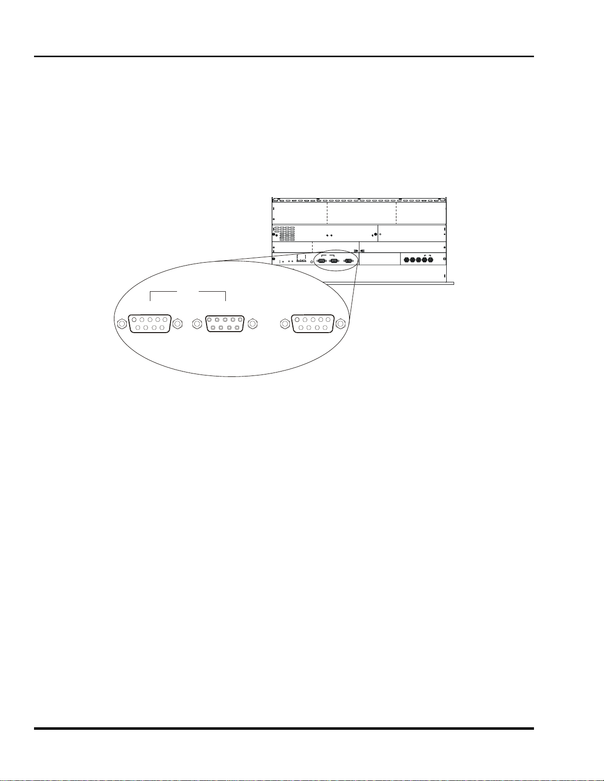
2.4 Serial Port Connections
Serial port connections are required when:
1. Using a Marquee signal switcher with the projector or
2. The system is to be controlled by a computer/third-party controller.
The projector's serial ports are located on the Control Module at the front panel of the electronic chassis. See
Figure 2-5.
RS-232
DIAGNOSTICS
V FAIL
ERROR
EHT
H FAIL
CLVPS
POWER
REMOTE
RESET
STANDBY
RS-232
IN
OUT SWITCHER
IN OUT
SWITCHER
HOR/COMPRED GREEN BLUE VERT
SYNC
Figure 2-5. Serial Port Connections
If using the system with a Marquee signal switcher, connect an RS-232 serial communication cable between the
switcher and the projector serial port labeled "SWITCHER". If the system is to be controlled by a computer or
third-party controller which has an RS-232 serial port, connect an RS-232 serial cable between the computer and
the projector serial port labeled "IN". After the connection is made, set the serial port baud rate as described in
the Projector Setup entry in Section 3.6.
Note: All serial connections require a 9 pin D connector at the projector end. Refer to Appendix D for cable
wiring requirements.
Note: For computer/controller control, PC software is required.
Note: The RS-232 serial port labeled "OUT" is provided for projector networking applications.
2-4 Installation & Setup
Artisan Technology Group - Quality Instrumentation ... Guaranteed | (888) 88-SOURCE | www.artisantg.com
Section 2
y
2.5 Optical Alignment
Optical alignment is required when the throw distance changes or the projector cannot be focused using the focus
controls. The projector is optically aligned at the factory at a fixed screen size and a fixed projector-to-screen
distance. If the throw distance has changed since the last setup, proceed as follows:
Note: The projector must be warmed up for at least 45 minutes prior to performing optical alignment.
Note: Optical alignment is both a mechanical and electrical adjustment. Electrical adjustments are stored in
the current setup memory. After alignment is complete, setup memories which were previously set up
(if any) must be set up again. Memory setup is explained in Section 2.7.
Note: Factory alignment is performed using the internal crosshatch with a 61.8 kHz signal applied.
It is recommended that optical alignment be performed using
the projector's Guided Mechanical Setup tutorial. This tutorial
displays step-by-step instructions during the alignment. The
instructions in this section require use of the Guided
Mechanical Setup tutorial.
To access and use the Guided Mechanical Setup tutorial, turn
on the projector [POWER] then press [HELP] at presentation
level. The Help menu is displayed. Next press [ 2 ] to select
Guided Mechanical Setup. The first page of the guide will be
displayed on the projection screen. When using the guide,
press [HELP] to display the next page, press [RECALL] to
display the previous page. When complete, press [EXIT] to
end Help.
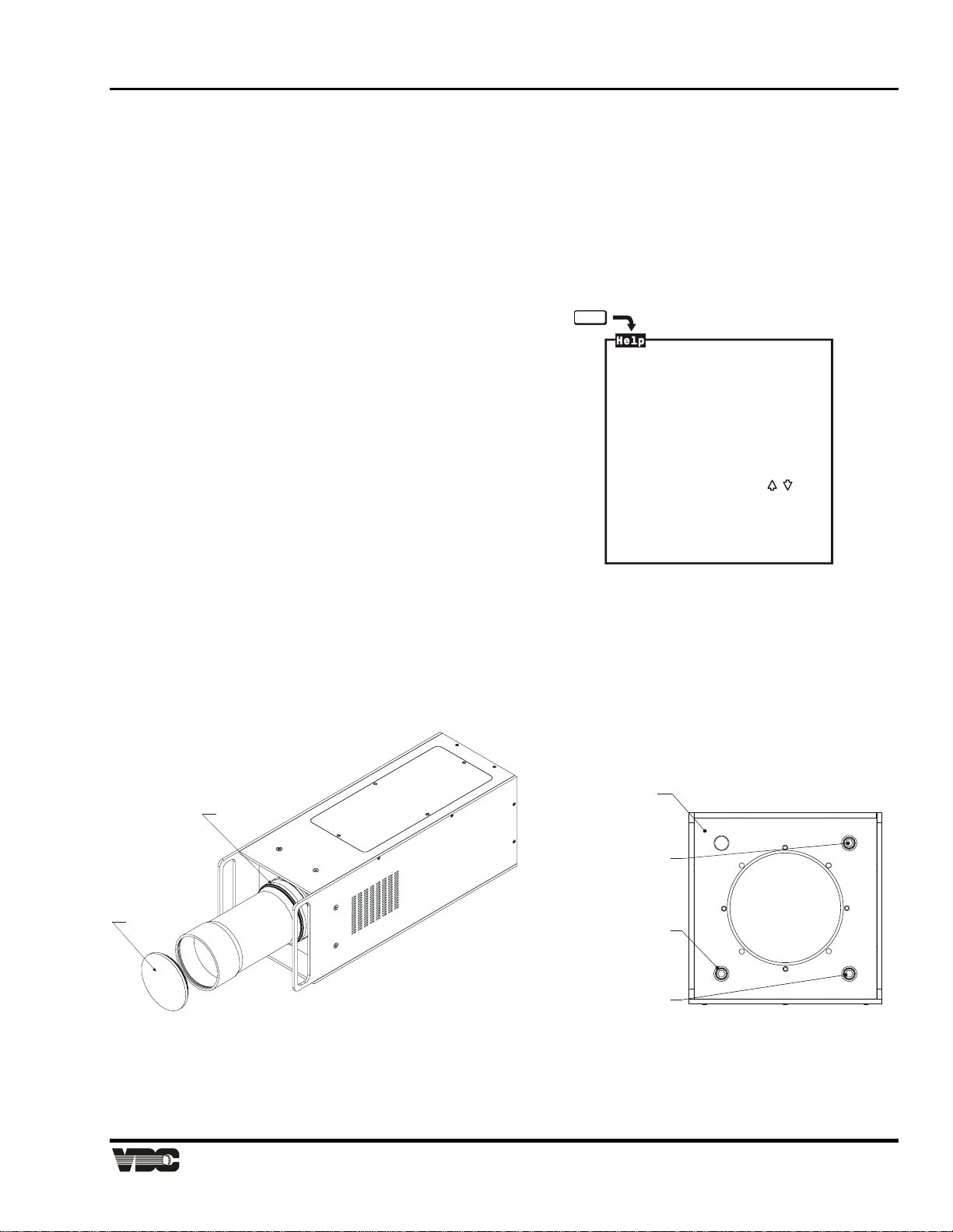
Examine the lens and hardware as shown in Figure 2-6. The
lens consists of a single focus barrel. The lens is secured in
place with a lens locking ring. Additionally, the lens consists of
a metal lens cover which is screwed in-place. To remove the
lens cover, rotate the cover counterclockwise (CCW) and place
in a secure location for reuse. To focus the lens, loosen the
lens locking ring. Note; the lens locking ring employs fine
threads and requires multiple turns. Once loosen, rotate the
lens barrel until the desired focus is achieved.
HELP
1. Guided Source Setup
2. Guided Mechanical Setup
3. Source Selection Guide
4. Keypad Guide
5. -
6. Using Help
For all menus:
Press a number or use
then <ENTER> to select item.
<HELP> for assistance
<RECALL> to go back one level
<EXIT> to return to picture
The CRT is attached to its lens by four (4)
socket head Allen screws located on the lens
mounting plate. The upper right screw (when
facing the lens) adjusts the focus between the
top and bottom of the picture, and the lower
left screw adjusts the focus between the left
and right sides of the picture. See Figure 2-6.
Lens Mounting
Plate
Top/Bottom
Focus Adjust
Left/Right
Focus Adjust
Factory/Service
Adjust Onl
LENS COVER
LENS LOCKING
RING
Figure 2-6. 8521 Lens Assembly
Step 1. Loosen the lens locking ring. Rotate the lens using until the picture is focused. Tighten the
locking ring.
Display Systems
Artisan Technology Group - Quality Instrumentation ... Guaranteed | (888) 88-SOURCE | www.artisantg.com
2-5
Marquee 8521 Ultra Green (HUD) User's Manual
e
A
r
A
A
Step 2. Step 3 requires that you look directly into the lens for adjustment. Before you continue, press
[▼] to reduce contrast to a low level (≥10%).
WARNING: DO NOT LOOK INTO THE LENSES IF CONTRAST IS SET TO NORMAL VIEWING LEVEL.
!
Step 3. Look directly into the lens. Press [▲], [▼],
[◄] or [►] to center the displayed
crosshatch on the face of the picture tube.
Step 4. Press [▲] to increase contrast to a normal
viewing level.
Befor
fte
Step 5. Press [▲] or [▼] to adjust for best electrical focus of the projected image.
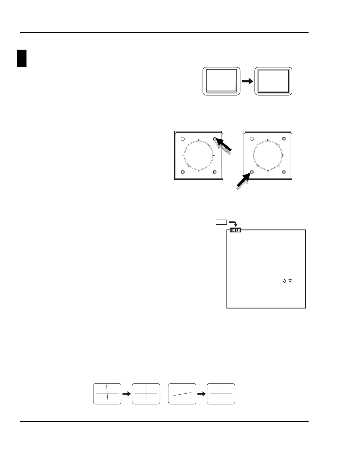
Step 6. An image is displayed. Loosen the lens locking ring and slightly defocus the center of the
picture.
a) Adjust the large Allen head bolt
located at the upper right corner of
the lens mounting plate. Turn the bolt
head until the top and bottom areas
of the picture are equally defocused.
b) Adjust the large Allen head bolt
located at the lower left corner of the
mounting plate. Turn the bolt head
until the left and right sides of the
picture are equally defocused.
Step 7. Readjust the lens focus for optimal overall focus. Tighten the lens locking ring.
2.6 Source Setup
This section gives step-by-step instructions for quick setup of the projector
for a selected external source. For a complete setup, repeat these steps
as required for each source connected to the projector.
Before starting, ensure that the projector is optically and mechanically
aligned. If optical alignment is required, follow the setup instructions in
Section 2.5. Select the source to be set up using the Source command,
and make sure it is visible on the projection screen.
To make setup easier, it is recommended that you use the projector's
Guided Source Setup tutorial. It provides source setup instructions on
screen to guide you through the adjustments. To access the tutorial, first
press [HELP] at presentation level. The Help menu is displayed. Next
press [ 1 ] to select Guided Source Setup. The first page of the guide will
be displayed on the projection screen. When using the guide, press
[HELP] to display the next page, press [RECALL] to display the previous page. When complete, press [EXIT].
Step 1. Press [BRITE] then [▲] or [▼] to increase or decrease the brightness setting until black areas
in the image just disappear.
Step 2. Press [CONT] then [▲] or [▼] to adjust the contrast of the image to a suitable level.
Step 3. Press [▲] or [▼] to adjust electrical focus for best overall sharpness.
Step 4. Press [▲] or [▼] to adjust skew until the vertical line through the center of the image is not
tilted (perpendicular to the horizontal line). Press [◄] or [►] until the center horizontal line is
perpendicular to the vertical.
HELP
1. Guided Source Setup
2. Guided Mechanical Setup
3. Source Selection Guide
4. Keypad Guide
5. -
6. Using Help
For all menus:
Press a number or use
then <ENTER> to select item.
<HELP> for assistance
<RECALL> to go back one level
<EXIT> to return to picture
Before
fter
Before
fter
2-6 Installation & Setup
Artisan Technology Group - Quality Instrumentation ... Guaranteed | (888) 88-SOURCE | www.artisantg.com
Section 2
A
A
r
A
r
A
A
A
A
A
A
A
r
A
r
A
A
A
A
r
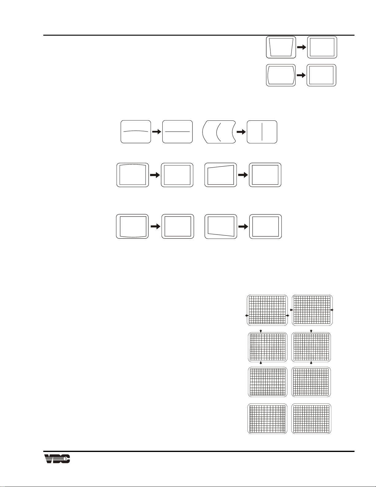
Step 5. Press [◄] or [►] to adjust keystone until the width at the
top of the picture is equal to the width at the bottom.
Step 6. Press [◄] or [►] to adjust side pincushion until the left and
BeforeBefore
fterAfter
right sides of the picture are straight and not curved.
fte
BeforeBefore
fte
Step 7. Press [▲] or [▼] to adjust vertical bow until the horizontal line at the middle of the picture is
straight. Press [◄] or [►] to adjust horizontal bow so that the vertical line at the middle of the
picture is straight.
Before
fter
Before
fter
Step 8. Press [▲] or [▼] to adjust top pincushion until the horizontal line at the top of the picture is
straight and not curved. Press [◄] or [►] to adjust top keystone so that the top edge is level.
fter
Before
Before
fter
fter
Before
Before
fter
Step 9. Press [▲] or [▼] to adjust bottom pincushion until the horizontal line at the bottom of the
picture is straight and not curved. Press [◄] or [►] to adjust bottom keystone so that the
bottom edge is level.
Before
fte
Before
fte
Step 10. Adjust C linearity as follows:
⇒ Press [▲] or [▼] until the horizontal line through the center of the crosshatch is equally distant
from the lines at the very top and bottom.
⇒ Press [◄] or [►] until the center of the crosshatch is equally distant from the vertical lines at
the left and right edges.
Step 11. Adjust S linearity as follows:
⇒ Press [▲] or [▼] until the height of each
crosshatch square is equal from the top
to the bottom.
⇒ Press [◄] or [►] until the width of each
crosshatch square is equal from the left
Before
fter
to the right.
Before
Before
Before
Display Systems
Artisan Technology Group - Quality Instrumentation ... Guaranteed | (888) 88-SOURCE | www.artisantg.com
2-7
fter
fter
fte

Marquee 8521 Ultra Green (HUD) User's Manual
e
r
e
r
Note: The source connected to the currently selected input should now be visible. If there is no picture,
check to see if the source is active.
Step 12. Press [▲] or [▼], [◄] or [►] to adjust
phase until the picture is centered on the
screen.
Befor
Afte
Step 13. Press [▲] or [▼], [◄] or [►] to adjust the
size of the picture. Ensure that objects in
your picture have the correct shape. For
example, if there is a circle in your picture,
size should be adjusted until the circle is
round, not oval.
Befor
Afte
Note: Remember that all of the adjustments above should be repeated for other sources in the system.
2.7 Memory Setup
This section explains how to set up projector memories to improve the performance of the projector's ASI and
ASR features. If you are not familiar with setup memories, read 0, prior to memory setup; in particular, read
Section3.3, Setup Memories, and the ASI with Save and Turn ASR On/Off entries in Section 3.6, Utility Features.
If the projector's setup memories are properly set up, the projector will be easier to use and operate.
Note: Memory setup should be performed when the projector is in its final operating position. If the physical
position of the projector changes, memory setup must be repeated.
Here is a brief summary of the setup memory, ASR, and ASI discussions in 0
2.7.1 About Setup Memories
The projector has 80 setup memories for storing display settings of different sources. Multiple setup memories
are required since display settings usually vary amongst sources. There are two types of setup memories: Input
and Recall. Both memory types store the same parameters. The only difference is that Input memories store
display settings for a particular physical input (e.g., switcher 0, slot 1) while Recall memories can be used with
any input.
At any one time, one setup memory is the current setup memory. The display settings in the current setup
memory are used for the current display. When a source is selected by entering its input number, the Input
memory for the selected input becomes the current setup memory*. If a Recall memory is selected, it becomes
the current setup memory*. Display adjustments are automatically saved in the setup memory which is current at
the time of adjustment (unless the setup memory is locked).
Note: If the ASR feature (explained below) is turned on during setup memory selection, the selected memory
may not be the current setup memory.
To display the Recall memories stored in the projector, press [UTIL] [ 3 ]. Press [UTIL] [ 4 ] to display the Input
memories. (Unused setup memories are not displayed).
2-8 Installation & Setup
Artisan Technology Group - Quality Instrumentation ... Guaranteed | (888) 88-SOURCE | www.artisantg.com

Section 2
2.7.2 About ASI and ASR
ASI (Automatic Source Interpolation) is a feature which automatically adjusts display settings based on the
settings of other setup memories stored in the projector. When a setup memory is first created, ASI automatically
generates its initial display settings. These settings will be created by copying another setup memory or by
interpolating multiple setup memories.
ASI is activated when:
• A new setup memory is created.
• An ASR is performed and its logic has activated an ASI.
• An "ASI with Save" is specified by the user (see Section 3.6).
ASR (Automatic Source Recall) is a feature which, when turned on for a given input, provides automatic Recall
memory selection or ASI adjustment. ASR processing can activate when:
• a change in scan frequencies is detected at the input,
• an input is selected,
• a Recall memory is selected, or
• a channel is selected.
This feature is primarily intended for use when many different sources must share the same input (via a third party
switcher, for example) or when a signal source can output several different scan frequencies (e.g., a SVGA card).
When a source switch is made, the projector may automatically select a Recall memory with matching scan
frequencies or create the display settings based on the settings in other setup memories.
2.7.3 Input Memory Setup
Follow these steps to prepare an Input memory for a source.
Note: To assure proper setup of an existing Input memory, ASR must be off (default) for the memory.
Step 1. Connect the source to the input to be set up, and then select the input using the Source
command. For example, if the source is connected to slot 1 of the projector, press [SOURCE]
[0] [1]. If the Input memory did not previously exist, it will be created automatically.
Step 2. The source should be displayed on the projection screen. If much adjustment is required,
press [UTIL] [ 1 ] [ 2 ] to perform an ASI with Save. The display appearance may improve
based on the settings stored in other setup memories. (If the Input memory is new, ASI with
Save will have
Step 3. Make display adjustments as required. Adjustment changes will automatically be saved in the
2.7.4 Recall Memory Setup
Follow these steps to prepare a Recall memory.
Step 1. Select the input connected to the source. For example, if the source is connected to switcher
1, slot 5, press [SOURCE] [ 1 ] [ 5 ]. The source should be displayed on the projection screen.
Step 2. To assure proper setup of a Recall memory, ASR must be off (default) for the current input.
Step 3. Select a Recall memory as the current setup memory. For example, to make Recall memory
03 the current setup memory, press [RECALL] [ 0 ] [ 3 ]. If the Recall memory did not
previously exist, it will be created automatically.
Step 4. If much adjustment is required, press [UTIL] [ 1 ] [ 2 ] to perform an "ASI with Save". (If the
Recall memory is new, ASI with Save will have already been performed when the memory was
Step 5. Make display adjustments as required. Adjustment changes will automatically be saved in the
Recall memory.
Display Systems
Artisan Technology Group - Quality Instrumentation ... Guaranteed | (888) 88-SOURCE | www.artisantg.com
2-9
Marquee 8521 Ultra Green (HUD) User's Manual
2.7.5 ASI Improvement
If the projector will be used with many sources, or new sources will be frequently added to the system, it is
recommended that five or six setup memories be created
expressly for the purpose of improving ASI accuracy. ASI
accuracy improves as more setup memories are created and
stored, and the variations amongst horizontal and vertical
scan frequencies increases. For example, if you always use
the same input and you never use Recall memories (thus
only one setup memory has ever been created), ASI will not
be effective. However, if many Input and Recall memories
have been used and adjusted for a variety of sources, the
projector has more "knowledge" in its database for
performing an ASI. As this "knowledge" increases, ASI
accuracy improves.
An easy way to add setup memories at various scan
frequencies is to use the projector's internal frequency
generator. The internal frequency generator can display a
test pattern using the scan frequencies you select. When
display adjustments are made, the display settings are stored in the current setup memory. Prepare a Recall
memory using the generator as follows:
Step 1. Select a Recall memory to be the current setup memory. For example, to make Recall memory
90 the current setup memory, press [RECALL] [ 9 ] [ 0 ]. (Recall memory numbers may be any
number from 01 to 99). If the selected Recall memory did not previously exist, it will be created
automatically.
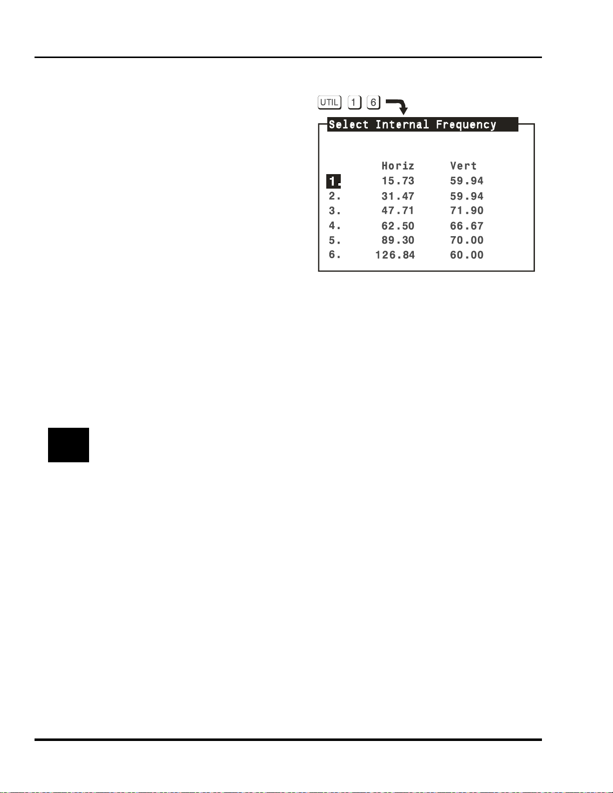
Step 2. Press [UTIL] [ 1 ] [ 6 ] to access the Internal Frequency Selection menu. Items one to six
contain preset scan frequencies covering the scan range of the projector. It is recommended
that Recall memories be created for each. To make a selection, enter an item number or use
[▲] and [▼] to move the cursor bar to the item you want, then press [ENTER].
It is recommended that Recall memories for the two extreme frequencies be set up first (Items 1 and
&
(You may notice that as new Recall memories are created, fewer display adjustments are required. This is
because ASI is using other setup memories to create the initial settings of the new memories.)
4). When other Recall memories are created, their initial display settings will be based on the
settings already stored in memory.
Step 3. At this point, a test pattern is displayed. Make display adjustments as required. All display
settings will be stored in the Recall memory. To create another Recall memory, repeat the
above steps. To return to the external source, press [EXIT] while only the test pattern is
displayed.
2-10 Installation & Setup
Artisan Technology Group - Quality Instrumentation ... Guaranteed | (888) 88-SOURCE | www.artisantg.com

Section 2
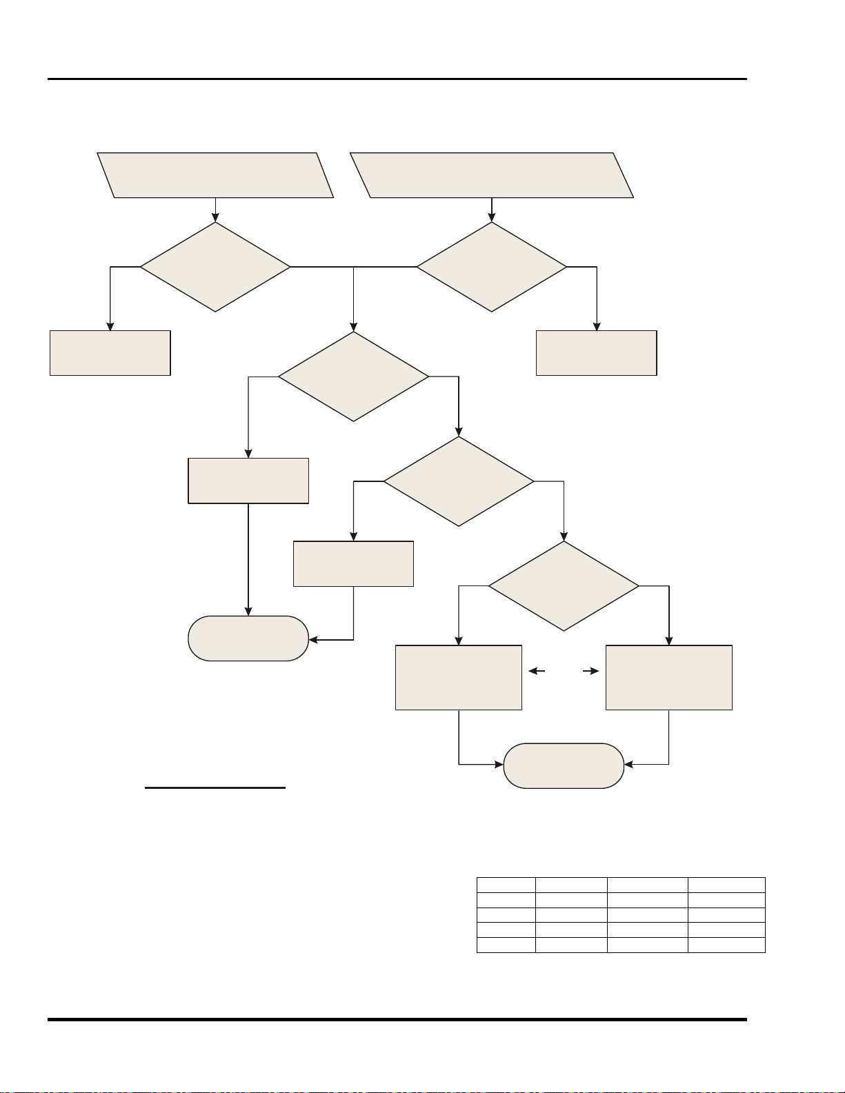
2.7.6 ASI with Save Logic Diagram
atch
yes no
Check the
Input memory of the
currently selected input for
matching H&V scan
frequencies.
UTIL
2
1
is pressed to perform
an "ASI with Save".
Display an
"ASI with Save"
confirmation box.
Was "Do It"
selected from the
confirmation box?
no match
Do nothing.
Return to presentation
level.
match
Search for a
Recall memory
with matching H&V scan
frequencies.
Copy the display
settings in the "matched"
match
memory to the current
setup memory.
"ASI with Save" Logic Diagram
no match
Search for an
Input memory
with matching H&V scan
frequencies.
memories for interpolation
and store the resulting
display settings in the
current setup memory.
no
match
Select two setup
Display Systems
Artisan Technology Group - Quality Instrumentation ... Guaranteed | (888) 88-SOURCE | www.artisantg.com
2-11
Marquee 8521 Ultra Green (HUD) User's Manual
A
A
2.7.7 ASR Setup
This subsection provides two examples of how the ASR feature may by used and set up.
2.7.7.1 ASR Logic Diagram
A change in scan frequency is detected.
The change is greater than 100 Hz horizontal
or greater than 1 Hz vertical.
no
Do nothing.
Is ASR
set to On for the
currently selected
input?
match
Change the current
setup memory to the
matched Input memory.
Adjustments made at
this point are stored
in the current
setup memory.
source, Recall memory, or channel was manually
selected. The H & V scan frequencies of the source
do not match that of the selected setup memory.
yes yes
Check the
Input memory of the
currently selected input for
matching H & V scan
frequencies.
matchmatch no match
Change the current
setup memory to the
matched Recall memory.
memory but do not update
the current setup memory.
Is ASR
set to On for the
selected
input?
no match
Search for a
Recall memory with
matching H & V scan
frequencies.
matchmatch no match
Use the display settings
of the matched Input
Search for an
Input memory with
matching H & V scan
frequencies.
no
Switch to the selected
source and/or setup
memory.
ASI
Logic
Begins
ASI
Functions
Create new display settings by interpolating the
two closest setup mem-
ories (in freq.). Do not
update the setup memory.
djustments made at this
point are displayed but
ASR Logic Diagram
NOT stored in the current
setup memory.
2.7.7.2 ASR Example #1
A computer is connected to slot 1 of the projector.
The graphics adapter in the computer can operate at
different frequency modes to accommodate various
software applications. The ASR feature may be
used until when the frequency mode of the computer
changes, the projector setup also changes to match
that of the new mode.
Source w/multiple scan rates / operating
modes.
MODE TYPE FREQ. (H) RECALL#
1 Text 31.5kHz 01
2 Graphics 35.6kHz 02
3 Graphics 64.0kHz 03
4 Graphics 110.0kHz 04
2-12 Installation & Setup
Artisan Technology Group - Quality Instrumentation ... Guaranteed | (888) 88-SOURCE | www.artisantg.com

Section 2
To prepare setup memories for the above system, follow these steps:
Step 1. Select the input using the Source command. Press [SOURCE] [ 0 ] [ 1 ] to select projector slot
1.
Step 2. Press [] twice to display the Current Input Parameters status page. Check to see if ASR is
off for the current input. If it is on, press [UTIL] [ 1 ] [ 4 ] to turn ASR off for the input. (It is
usually easier to prepare setup memories when ASR is turned off.)
Step 3. At the computer, switch to an application which uses one of the graphics adapter operating
modes. Select an unused Recall memory as the current setup memory. For example, to make
Recall memory 01 the current setup memory, press [RECALL] [ 0 ] [ 1 ]. Make display
adjustments as required. The display settings for the current graphics mode will be stored in
the Recall memory. Repeat this step for the remaining graphics adapter operating modes,
storing adjustments for them in Recall memories 02, 03 and 04. It is recommended that the
two extreme frequencies be set up first.
Step 4. Press [SOURCE] [ 0 ] [ 1 ] to make Input memory 01 the current setup memory then press
[UTIL] [ 1 ] [ 5 ] to display the Clear Setup dialog box. Move the cursor to "Do It" then press
[ENTER] to clear the display and frequency settings of the input. Now Input memory 01 will not
be used during an ASR search.
Step 5. Press [UTIL] [ 1 ] [ 3 ] to lock Input memory 01 to prevent display or frequency changes to the
Input memory.
Step 6. Press [UTIL] [ 1 ] [ 4 ] to turn ASR on for the input. Now, each time the computer's graphics
adapter switches operating modes, the projector will automatically adjust its display settings to
suit the new mode.
2.7.7.3 ASR Example #2
Six different sources are connected to a third party (non-Reseller) signal switcher. Unlike the Marquee signal
switcher, this third party switcher is not controlled by the keypad. Under normal circumstances, the projector is
not aware of source switches made by the switcher. However, if ASR is turned on for the input, and a Recall
memory has been set up for each source device, the projector will detect the external source switch and
automatically select the appropriate Recall memory. Even if Recall memories have not been set up but ASR is
on, ASR will try to adjust the display settings based on the settings of other Input or Recall memories.
To prepare setup memories for this system, follow these steps:
Step 1. Connect the output of the signal switcher to a projector input or a Marquee signal switcher
input. Select the input using the Source command. For this example, press [SOURCE] [ 0 ]
[ 1 ] to select projector slot 1.
Step 2. Press [] twice to display the Current Input Parameters status page. Check to see if ASR is
off for the current input. If it is on, press [EXIT] then press [UTIL] [ 1 ] [ 4 ] to turn ASR off for
the input.
Step 3. At the switcher, switch in one of the source devices. Select an unused Recall memory as the
current setup memory. For example, to make Recall memory 01 the current setup memory,
press [RECALL] [ 0 ] [ 1 ]. Make display adjustments as required. The display settings for the
selected device will be stored in the Recall memory. Repeat this step for the remaining
devices.
Step 4. Press [UTIL] [ 1 ] [ 5 ] to display the Clear Setup dialog box. Move the cursor to "Do It" then
press [ENTER] to clear the display settings and frequency settings of the input. By doing this,
Input memory 01 will not be used during an ASR search.
Step 5. Press [UTIL] [ 1 ] [ 3 ] to lock Input memory 01 to prevent display or frequency changes to the
Input memory.
Step 6. Press [UTIL] [ 1 ] [ 4 ] to turn ASR on for the input. The projector's display settings will
automatically adjust to match the source selected by the switcher.
Display Systems
Artisan Technology Group - Quality Instrumentation ... Guaranteed | (888) 88-SOURCE | www.artisantg.com
2-13

Marquee 8521 Ultra Green (HUD) User's Manual
This Page Intentionally Left Blank
2-14 Installation & Setup
Artisan Technology Group - Quality Instrumentation ... Guaranteed | (888) 88-SOURCE | www.artisantg.com

Section 3 Operation
3.1 Overview
This section explains how to operate the projector once it has been installed and is ready for use. If you have not
yet set up the projector, refer to Section 2, Installation and Setup.
Before using the projector for the first time, it is recommended that you read through this section of the manual.
Although the projector is easy to use, there are many advanced features which allow you to enhance performance
and operation. By understanding these features, and how to use them, you will soon be able to take full
advantage of the projector's extensive capabilities.
3.1.1 Projector Basics
Notice that the projector has no knobs or moving parts to make adjustments or change control settings. This is
because all user adjustments are digitally controlled via the projector's keypad. Adjustment settings are retained
in the projector's internal memory, even when the projector is unplugged.
3.1.2 Keypads
Four types of keypads may be used with the projector: built-in, IR remote, wired remote, and Presenter's. The
projector includes a multi-use, full function, backlit keypad which is factory configured for use as a built-in keypad.
It can easily be reconfigured for use as an IR remote keypad or a wired remote keypad. Use the keypad type
which is most appropriate for your application.
Note: For information on how to reconfigure the keypad, refer to Section 2.2.2. To convert the keypad to a
wired remote keypad, an optional accessory cable (#03-001106-02P) is required.
Note: Additional keypads are available from your reseller and VDC Display Systems.
3.1.3 IR Remote Keypad
When the keypad is configured for IR remote operation, you can control the projector from a distance without a
wired connection to the projector. The keypad includes a battery powered infrared (IR) transmitter.
3.1.4 Wired Remote Keypad
When the keypad is configured as a wired remote keypad, you can control the projector from a distance by way of
a 25 ft extension cable (accessory cable required). Wired remote keypad operation is recommended when:
1. the location of the keypad with respect to the projector or screen is inadequate for IR remote keypad
operation
2. the projector is in a lighting environment which is unsuitable for IR remote keypad operation, or
3. there are multiple projectors in the same room and you want each projector to be controlled by its own
remote keypad
3.1.5 Presenter's Keypad (optional)
The Presenter's Keypad is similar to the IR remote keypad (above) except that it is not a full function keypad; it
contains only frequently used keys. Presenters may find this keypad is easier to use than a full function keypad.
For more information about the Presenter's Keypad, call your reseller or VDC Display Systems.
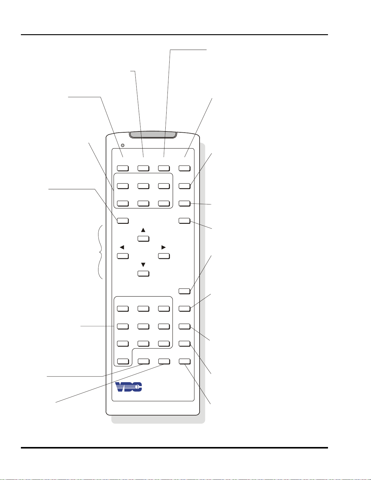
Figure 3-1 shows the projector functions which are accessible from the multi-use (full function) keypad. As you
may notice from the illustration, some keys provide direct access to specific functions (such as [POWER] to turn
the projector on or off), and some keys provide indirect function access via menus. Functions which are less
frequently accessed are provided through on-screen menus.
Display Systems
Artisan Technology Group - Quality Instrumentation ... Guaranteed | (888) 88-SOURCE | www.artisantg.com
3-1
Marquee 8521 Ultra Green (HUD) User's Manual
Utilities M
Status Page
to display status
pages
enu
To access the following utilities:
Source Setup
Channel List
Memories Display
Preferences
Remote Options
Clock/Events
Service
Projector
to command a single
projector in a multi projector system
Display Controls
To adjust:
Color
Tint
Detail
Contrast
Brightness
Volume
Enter
to select a highlighted
menu item
to select a dialog box
option
Arrow Keys
for adjustments
for menu item selection
for movement between
edit fields
PROJ UTIL PIC
COLOR
CONT
ENTER
*
TINT
BRITE
DETAIL
VOL
GEOM
CONV
SOURCE
EXIT
Picture Menu
To adjust or set:
Phase
Size
White Balance
Focus
Sync
Blanking
Clamping
Retrace
Decoder Options
Geometry Menu
To adjust:
Size
Keystone
Side Pin
Top
Bottom
Bow
C Linearity
S Linearity
Skew
Convergence Menu
to adjust red, green and
blue convergence
Exit
to exit from a menu or
function
Source
for input selection
for channel up/down selection
for source message display
Recall
Numeric Keys
for menu item selection
for number entry
Mute
to turn audio on or off
123RECALL
HELP
4
7
0MUTESTBY
5
8
6
9
#
POWER
Display Systems
to select a Recall Memory
to go back one screen during
menu/help display
to view hidden slide bars
when message display is turned off
Help
for context sensitive help
for setup guides
# Test Pattern
to select a test pattern for display
Standby
to turn both picture and
audio on or off
Figure 3-1. Full Function Keypad
3-2 Operation
Power
to turn the projector on or off
Artisan Technology Group - Quality Instrumentation ... Guaranteed | (888) 88-SOURCE | www.artisantg.com

Section 3
3.1.6 Keypad Usage
The keypad is used the same way you would use a remote keypad supplied with a TV or VCR. There are only a
few general key press rules to keep in mind:
Key Press Rules
1. All key presses are in sequence; no functions require simultaneous key presses.
2. [POWER] and [STBY] are the only keys which require an extended hold-down for function activation
(about one second). For all other keys, a momentary press will activate the key's function.
3. [▲], [▼], [◄] and [►] are the only keys which repeat when held down. For all other keys, the key must
first be released then pressed again for repeated activation.
4. Pressing [EXIT] always exits the current function, operation, menu, or dialog box.
Note: To toggle the keypad's backlit display (enable or disable), press [] [BRITE] [TINT] [DETAIL] [3] See
Section 2.2 for details.
Note: If keys are pressed at a time when the projector is busy (such as during power-up), the key presses
may not take effect.
When the projector is turned on, it begins operation at Presentation Level. Presentation level is the normal level
of operation at which a source image is (or may be) displayed. The projector temporarily leaves presentation
level when menus are displayed, control settings are changed, or online help is accessed. The screen display
changes to reflect the operation or function being performed. One or more of the following may be displayed:
1 Slidebar - to make adjustments to display settings.
2 Menu - to select projector functions or change projector settings.
3 Dialog Box - to select an action such as confirm or cancel an operation.
4 Message Box - to display messages.
5 Help Page - to display help and provide assistance.
6 Test Pattern - to assist during setup.
Note: The display of slidebars and messages can be suppressed if desired. For more information, refer to
Section 3.6, Utility Features).
Each of the above are explained in the following entries. As you read through the explanations, note the
following:
In most cases...
[EXIT] brings you back to presentation level,
[RECALL] brings you back to the previous page or menu,
[ENTER] is pressed to make a selection, and
[HELP] provides context-sensitive help.
3.1.7 Slidebars
When an adjustment is made, a slidebar is superimposed on the projection screen. The slidebar displays the
adjustment setting on a percentage scale. To make an adjustment, use the arrow keys indicated by the slidebar.
Press [EXIT] to end an adjustment or, for a slidebar accessed from a menu, press [ENTER]. If no keys are
pressed within 5 seconds while a slidebar is displayed, the slidebar disappears.
For example, if [CONT
contrast is set to 50%. Press [▲] or [▼] on the keypad to change the
contrast level. When complete, press [EXIT].
] is pressed, the Contrast slidebar is superimposed on the image. The slidebar shows that
Display Systems
Artisan Technology Group - Quality Instrumentation ... Guaranteed | (888) 88-SOURCE | www.artisantg.com
3-3

Marquee 8521 Ultra Green (HUD) User's Manual
3.1.8 Menus
When a menu key is pressed or a menu is selected, a menu with a list of selection items is superimposed on the
projection screen. Each menu consists of a title, selection items, and a cursor bar. Selection items may include
adjustment functions, control settings or other menus.
To make a selection from the menu, either:
1. press the number key corresponding to the item
number, or
2. press [▲] or [▼] to move the cursor bar to the
desired item, then press [ENTER]
If a menu item includes control options, for example, items
5, 7 and 8 above, the control option setting can be
changed by pressing the number key or by pressing
Title
Selection
Items
1.
Phase
2. Size
3. White Balance
4. Focus
5. Sync: Slow
6. Blanking
7. Auto Clamp: Off
8. Retrace: Long
9. Decoder Options
Cursor
Bar
[ENTER] when the item is highlighted.
Note: Pressing [RECALL] while in a sub-menu returns you to the previous menu.
3.1.9 Dialog Boxes
Dialog boxes are displayed when the projector requires an action to be chosen
by the user.
Exit Convergence
No
Save
Continue
Adjust
For example, after a convergence registration is performed, a dialog box is displayed to confirm that the new
convergence settings are to be saved in memory. Press [◄] or [►] to highlight one of the actions then press
[ENTER] or [EXIT] to perform the action. If [ENTER] is pressed, the previous menu is then displayed. If [EXIT] is
pressed, the projector returns to presentation level.
3.1.10 Message Boxes
Message boxes display brief messages on the screen to indicate a status, condition, or error. Messages are
overlaid on the displayed source image and in most cases remain on the screen for about five seconds. To
remove a message box prior to the five second display period, press [EXIT].
3.1.11 Help Pages
Help pages provide assistance when you need it. There are various forms of help available, all accessible by
pressing [HELP]. For information about using help, refer to the Using Help entry in this section.
To advance one page when using help, press [HELP].To go back one help page, press [RECALL]. To exit from a
help page, press [EXIT].
3.1.12 Test Patterns
The projector has an internal generator which can display several different types of test patterns to assist you
during projector setup. Press [ # ] to display the first test pattern ─ the external source. Each subsequent press
of [ # ] changes the test pattern as shown below. If a test pattern is the only graphic displayed (i.e., no overlaid
text), pressing [EXIT] returns the display to the external image.
Presentation
Level
Presentation
Level
Standard
Crosshatch
Dots
Grey
Scale
White
Screen
Fine
Crosshatch
Figure 3-2. Test Patterns and Selection
Note: Test patterns are normally generated at the scan frequencies of the current input signal.
3-4 Operation
Artisan Technology Group - Quality Instrumentation ... Guaranteed | (888) 88-SOURCE | www.artisantg.com

Section 3
3.1.13 Using Help
The projector includes an extensive online help system. The help system provides operation guidance and
assistance. There are two types of online help: Context Sensitive Help and Guided Help.
3.1.13.1 Context Sensitive Help
Context Sensitive Help provides help on how to use a specific function.
To view help pertaining to a dedicated key function, press the key then press [HELP]. For example, to view a
help page which describes how to use the brightness function, press [BRITE] [HELP].
To view help pertaining to a menu selectable function select the function then press [HELP].
To view help describing a menu, press [HELP] while the menu is displayed.
If multiple pages are available, press [HELP] to advance to the next page. Press [RECALL] to go back to the
previous page. To end help, press [EXIT].
3.1.13.2 Guided Help
HELP
Guided Help provides several online tutorials which explain
how to operate the projector and assist you during installation
and setup.
To access the tutorials, press [HELP] at presentation level.
The Help menu is displayed. When using tutorials, press
[HELP] to display the next tutorial page, press [RECALL] to
1. Guided Source Setup
2. Guided Mechanical Setup
3. Source Selection Guide
4. Keypad Guide
5. -
6. Using Help
display the previous page, press [EXIT] to end help.
1. Guided Source Setup
The Guided Source Setup tutorial provides step-by-step
instructions for quick setup of the projector with the currently
selected external source. Setup may be performed while
proceeding through the tutorial.
For all menus:
Press a number or use
then <ENTER> to select item.
<HELP> for assistance
<RECALL> to go back one level
<EXIT> to return to picture
Note: During the tutorial, [RECALL] displays the previous
page and [EXIT] returns you to presentation level (this includes when slidebars are displayed).
Note: If the display cannot be focused, ensure that the throw distance is correct. If the screen distance is
correct but the display cannot be focused, follow the Guided Mechanical Setup tutorial.
2. Guided Mechanical Setup
The Guided Mechanical Setup tutorial provides step-by-step instructions for mechanical and optical
setup of the projector. This setup is necessary during initial installation and also when the screen
size changes, the throw distance changes, or the display image does not focus using the focus
control. For more details, refer to Section 2.5.
3. Source Selection Guide
The Source Selection Guide explains various source selection methods.
4. Keypad Guide
The Keypad Guide explains how to use the keypad.
5. Using Help
Using Help provides instructions on how to use the help system.
Display Systems
Artisan Technology Group - Quality Instrumentation ... Guaranteed | (888) 88-SOURCE | www.artisantg.com
3-5
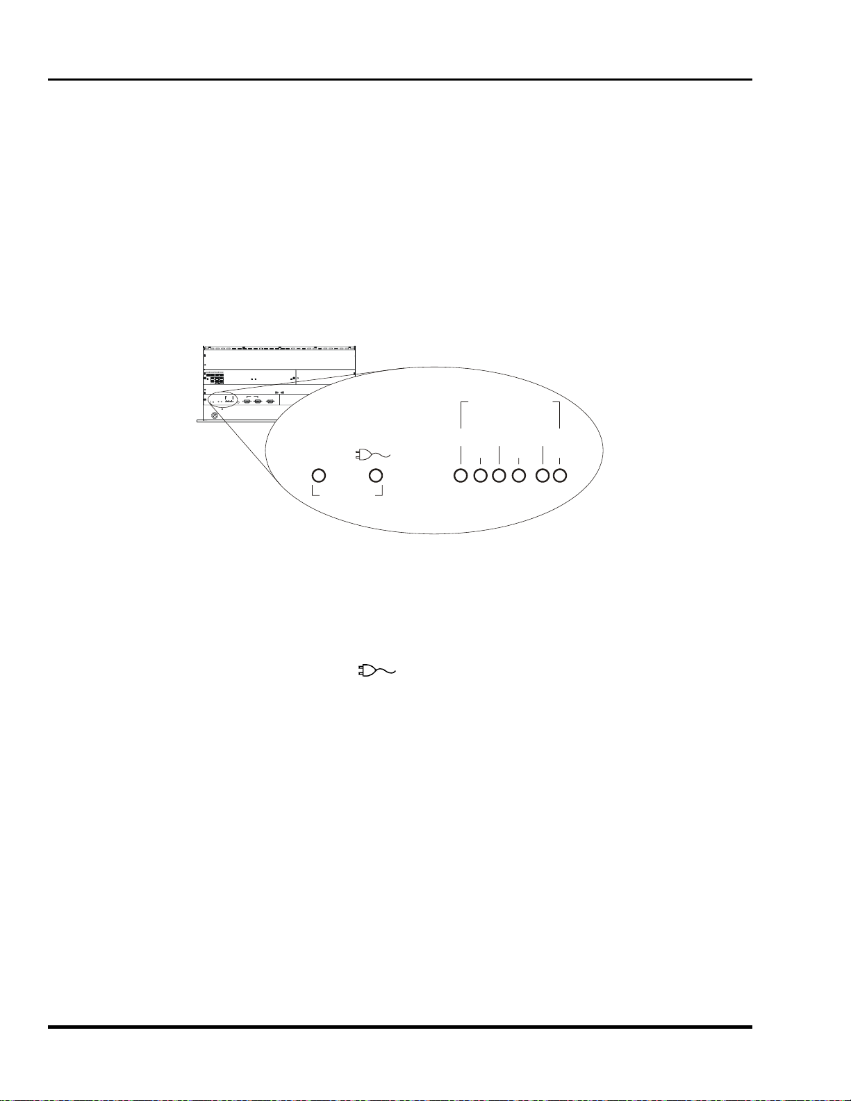
Marquee 8521 Ultra Green (HUD) User's Manual
3.1.14 Power-on
To turn on the projector, press [POWER] on the keypad. Hold [POWER] down for about one second. If using an
IR remote keypad, point the keypad at the projection screen or the front of the projector. During power-on, the
projector proceeds through a series of internal diagnostic tests which last approximately 9 seconds. Once
complete, an input image should be displayed on the projection screen. If no image is displayed, press
[SOURCE] to display the source message. The source message displays the currently selected input. Check
that the correct source is indicated on the display.
If there is no display when [] is pressed, check the LEDs (Light Emitting Diodes) on the projector front panel.
Only the green POWER LED should be lit. If any of the red diagnostics LEDs are lit, call your reseller for
assistance.
Note: Allow the projector to warm up for 45 minutes before use. Critical adjustments should be performed
after the warm-up period.
Note: Turning the projector off via a remote or built-in keypad places the projector in a "wait to operate"
mode. To remove power from the projector, unplug the power cord.
DIAGNOSTICS
POWER
0
ERROR EHT
1
STANDBY
V. FAI L
H.FAIL
CLVPS
Figure 3-3. Rear Panel LEDs
3.1.15 Standby Mode
Standby Mode allows you to blank the display and mute the audio output while keeping the projector in a warmedup and ready state.
To enter standby mode, hold down [STBY] for about one second while at presentation level. The display blanks.
Both the green POWER LED and the yellow LED are lit. To leave standby mode, hold down [STBY] or [EXIT] for
one second. The display is then restored and the
LED is turned off.
Note: During presentations, the standby feature is useful when you want to direct audience attention away
from the projection screen.
Note: To prolong CRT life, it is recommended that the standby feature be used when the display is not
required.
3.1.16 Audio Functions
The Marquee 8521 does not support the audio feature
3-6 Operation
Artisan Technology Group - Quality Instrumentation ... Guaranteed | (888) 88-SOURCE | www.artisantg.com

0
esentatio
P
l
3.1.17 System Status Pages
resentation Leve
The projector's current operating settings may be
displayed by pressing [] while at presentation
level. Each time [] is pressed, one of three main
Page 1
status pages is displayed. To return to presentation
level, press [EXIT].
Page 1; displays general projector information and
operating settings which include identity, software
version, date and time, keypad type, scan
configuration, auto power-up setting, message
display setting, switchers (numbers) connected,
installed options, and mute setting. Operating
settings are explained in the following entries in this
section.
Projector No:
IR Sensor:
Remote Jack:
Auto Power-up:
VDC Display Systems
Marquee
Messages:
Mute:
XXXX
000
A
A
Off
On
Off
Serial No:
Software:
Date:
Horiz Scan:
Vert Scan:
Switchers:
Options:
123456789
VX.X
xx/xx/xx
03:05 pm
Normal
Normal
1
CMM
ACON
Page 2; displays current input parameters. These
parameters (defined later in this section), relate
specifically to the currently selected input.
Page 2
Page 3; lists the display settings currently in use.
Note: If the current setup memory is locked or an
ASI has occurred, the display settings shown may
not be identical to those stored in the setup memory.
Note: To view help pages pertaining to the
status pages and their contents,
press [HELP] during status page display.
"Time" does not update on-screen.
Current Input Parameters
Channel:
Switcher:
Recall:
Input Module:
Horiz Freq:
Vert Freq:
Signal Type:
Sync Type:
Video Standard:
Slot:
ASR:
12 Computer A
1
4
01
On
Built-in RGB
75.00 kHz
72.67 Hz
RGB
Sync-On-Green
-
Page 3
Current Display Settings
Channel:
Contrast:
Bright:
Volume:
Color:
Tint:
Detail:
Retrace:
Sync:
Auto Clamp:
30
50
0
50
50
25
Long
Slow
On
Recall:
Pr
Figure 3-4. System Status Pages
Input:
12 Computer A
14
01
H Size:
V Size:
Keystone:
Side Pin:
Top Pin:
Bot Pin:
V Bo w:
H C Lin:
V C Lin:
H S Lin:
V S Lin:
H Skew:
50
50
50
50
50
50
50
50
50
50
50
50
n Level
H Phase:
V Phase:
White Bal:
(6500K)
Focus:
T Blank:
B Blank:
L Blank:
R Blank:
H Bow :
V Skew:
50
50
2
50
0
0
0
0
50
50
Display Systems
Artisan Technology Group - Quality Instrumentation ... Guaranteed | (888) 88-SOURCE | www.artisantg.com
3-7
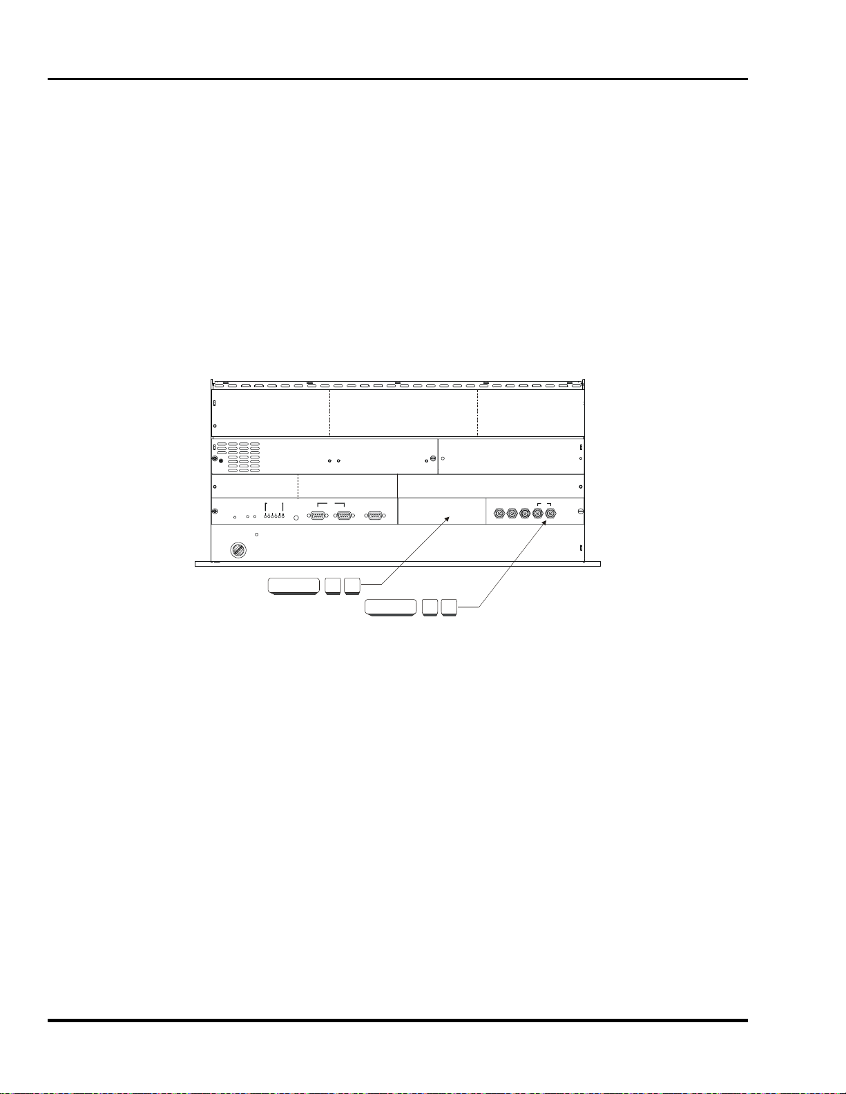
Marquee 8521 Ultra Green (HUD) User's Manual
3.2 Source Selection
The projector includes a built-in RGB input interface to accept a single input. With optional accessories such as a
Marquee Multi-standard Decoder, and the use of one or more external switchers, the number of inputs can be
significantly increased. Because of this large capability, three source selection methods are available: Input
Selection, Direct Channel Selection, and Up/Down Channel Selection. Sources are selected at presentation
level.
Note: For systems with only one or two source connections, direct input selection may be the only method
you will use. If your system includes many sources, all methods will be of interest.
Note: Internal sources are also selectable for use during setup and testing. To select an internal source,
refer to Section 3.1.12, and Section 3.6.
3.2.1 Input Selection
This method is the most basic of the three source selection methods. A source is selected by specifying the input
to which the source is connected, defined by a switcher number and slot number. For the purposes of input
selection, the projector is considered to be a type of switcher. Projector slots are illustrated in Figure 3-5 below.
Each slot can accept one external input signal for display.
POWER
RESET
STANDBY
DIAGNOSTICS
V FAIL
ERROR
EHT
H FAIL
CLVPS
SOURCE 0 2
RS-232
IN OU T
REMOTE
SWITCHER
SOURCE 0 1
SYNC
HOR/COMPRED GREEN BLUE VERT
Figure 3-5. Projector Slots
To select an input:
Press [SOURCE] [ m ] [ n ] at presentation level.
where: m = 0 (projector) or 1-9 (switcher 1, 2, ... 9)
n = 1-9 (slot number)
The projector switches to, and displays, the source connected to the input selected. The projector also uses the
display settings previously set in memory for that input. If the selected input is invalid, a warning message is
displayed. An example of an invalid input might be "0 1" when a switcher is connected to slot 1 of the projector.
Another example of an invalid input would be to select a switcher which does not physically exist.
Example 1
Slot 1 on the projector has the output from a computer workstation connected to it. To display the workstation
output, press [SOURCE] [ 0 ] [ 1 ].
Example 2
A single Marquee signal switcher is connected to the projector and a computer is connected to slot 3 of the
switcher. To display the computer output, press [SOURCE] [ 1
] [ 3 ].
3-8 Operation
Artisan Technology Group - Quality Instrumentation ... Guaranteed | (888) 88-SOURCE | www.artisantg.com

Section 3
3.2.1.1 Direct Channel Selection
This method of source selection takes advantage of the Channel List feature explained in Section 3.6, Utility
Features. The Channel List allows you to assign a source to a 2-digit number, from 01 to 99.
Once you have assigned channel numbers to your sources, and the projector is at presentation level, you can
select a source by pressing the 2-digit channel number associated with it.
To select a channel, press [ m ] [ n ].
where: m = the 1st digit of the channel number
n = the 2nd digit of the channel number
The projector switches to, and displays, the source assigned to the channel number. If an invalid switcher or slot
number is assigned to the channel, a warning message is displayed.
Example
Channel 08 in the Channel List was programmed to select a source connected to slot 5 on switcher 3. To select
this source, simply press [ 0 ] [ 8 ].
Note: Note: If the Channel Select option in the Preferences menu ([UTIL] [ 5 ] [ 4 ] ) is set to either "1 digit
only " or "1 or 2 Digits", the preceding zero shown in the example above does not have to be entered.
For more information, refer to the Preferences entry in Section 3.6.
3.2.1.2 Up/Down Channel Selection
This method of source selection also takes advantage of the Channel List feature. It lets you quickly switch
between channels programmed in the Channel List by using the up and down arrow keys on the keypad.
To make a selection:
Press [SOURCE] followed by [▲] or [▼].
Each time an arrow key is pressed, a channel number (and name) is displayed on the screen. When the channel
number you want is displayed, simply wait to allow the projector to switch to the source defined by the channel.
Note: If a channel specifies a switcher which does not exist, the channel is considered invalid.
Note: The Channel List utility allows you to flag the channels to be used by the Up/Down Channel selection
feature. For more information, refer to the Channel List entry in Section 3.6, Utility Features.
Display Systems
Artisan Technology Group - Quality Instrumentation ... Guaranteed | (888) 88-SOURCE | www.artisantg.com
3-9

Marquee 8521 Ultra Green (HUD) User's Manual
3.2.1.3 The Source Message
When [SOURCE] or [RECALL] is pressed at presentation level, and/or a source switch is made, a source
message is briefly overlaid on the projection screen. The source message displays current source information.
Note: 1) If screen messages are turned off via the Preferences menu ([UTIL] [ 5 ] [ 2 ] ), the source
message is not displayed. 2) During input selection or Recall memory selection (explained later), the
message box displays numeric keypad entries as they occur. In both cases, two digits must be
entered. If only one digit is entered, the message box will remain displayed until a second digit is
entered or the selection is cancelled by pressing [EXIT]. 3) When an internal source is in use, an
internal source message is displayed.
Channel Number
If a channel has been selected, the channel number is displayed; otherwise this line is blank.
Source Name
If a channel was selected and a source name was defined for it in the Channel List, the name is displayed here;
otherwise this line is blank.
Input Number
The switcher and slot number of the active input is displayed. If the switcher number is 0, the input is on the
projector (versus on a switcher). The slot number may indicate a projector slot or a switcher slot.
If the Input memory for the input is in use and locked, a key icon (
) is displayed. Setup memories which are
locked are not affected by adjustments to display settings. For an explanation of Input memories and locked
memories, refer to Section 3.3.
Recall Memory Number
When a Recall memory is in use, the Recall memory number is displayed; otherwise this line is blank.
If the Recall memory is locked, a key icon (
) is displayed. Setup memories which are locked are not
affected by display adjustment changes. For an explanation of Recall memories and locked memories, refer to
Section 3.3.Setup Memories
ASI Message
If the ASR feature is set to ON for the Input memory, and an ASI has occurred, an ASI message is displayed;
otherwise this line is blank. The message indicates which memories were used for interpolation to produce the
current display settings. When this line is visible, adjustments to display settings will NOT be stored in the current
setup memory. For more information about the ASR feature and ASI, refer to the Source Setup entry in Section
3.6, Utility Features.
3.3 Setup Memories
3.3.1 Memories
The projector has 80 setup memories which store display settings. Multiple setup memories are needed because
display settings are usually different for different sources. For example, the display settings (brightness, contrast,
convergence, etc.) when using a VCR may be very different than the settings for a high resolution computer
output. When display adjustments are made, the new settings are automatically saved in one of the projector's
setup memories.
There are two types of setup memories: Input and Recall. Both memory types store the same parameters. The
only difference is that Input memories store display settings for a particular physical input (e.g., switcher 0, slot 1)
while Recall memories can be used with any input.
At any one time, one setup memory is the current setup memory. The display settings in the current setup
memory are used for the current display. When a source is selected by entering its input number, the Input
memory for the selected input becomes the current setup memory (unless ASR is on and is triggered). If a Recall
memory is selected, it becomes the current setup memory. Display adjustments are automatically saved in the
setup memory which is current at the time of adjustment (unless the setup memory is locked ─ explained later).
3-10 Operation
Artisan Technology Group - Quality Instrumentation ... Guaranteed | (888) 88-SOURCE | www.artisantg.com

Section 3
3.3.2 Input Memories
As mentioned above, Input memories store display settings for each
physical input (i.e., switcher 0, slot 1). When an input is selected,
the Input memory for that input becomes the current setup memory
and its display settings are used (unless ASR is on and is
triggered). If the input is being selected for the first time, a new
Input memory is created.
3.3.3 Recall Memories
Recall memories provide an alternative to using the display settings
stored in the Input memory of the selected source. For example,
you may want to temporarily disconnect a computer connected to
the projector's RGB input and in its place, connect another
computer with different signal characteristics. Since the connection
is only temporary you don't want to change the display settings
stored in the Input memory. Instead, you can select a Recall
memory which has the settings you want for the new input. If there
are many devices which will be sharing the same input, many
Recall memories can be created to store the display settings for
each. On the other hand, if there are many sources on different
inputs with exactly the same signal characteristics, it may be
possible for them to share the same Recall memory.
Recall memories are identified by a two digit number. Any number
from 01 to 99 can be assigned, although only 80 memory spaces
exist.
To select or create a Recall memory:
Press [RECALL] [ m ] [ n ].
where: m = the 1st digit of the Recall memory number
n = the 2nd digit of the Recall memory number
For example, to select Recall memory 01, press [RECALL] [ 0 ]
[ 1 ]. Recall memory 01 will then be the current setup memory and
its settings will be used for the currently selected source. If this is
the first time that the Recall memory number is used, a new Recall
memory is created. Any display adjustments you make will be
stored in the Recall memory.
3.3.4 Memory Allocation
Each time a setup memory is selected the projector checks its memory bank to see if the selected memory exists.
If it does exist, it uses the memory and its display settings. If it does not exist, a small portion of memory is
allocated for the new setup. Space is available for up to 80 setup memories. When the last space is used up, a
warning message is displayed. If this happens, call for servicing to delete memories which you no longer use to
make room for new memories.
3.3.5 Locking Setup Memories
Setup memories may be locked or unlocked. Locking a setup memory prevents adjustments to display settings
from being saved in that memory. For example, if Recall memory 08 is locked and selected, then brightness is
adjusted, the new brightness setting is only temporary. If the setup memory is then reselected, the original
brightness setting will be restored.
Note: When a locked setup memory is selected, a key icon (
) is displayed in the Source Message.
To lock or unlock the current setup memory, select option 3 from the Source Setup menu
([UTIL] [ 1 ] [ 3 ] ). Option 3 indicates the current setting.
Display Systems
Artisan Technology Group - Quality Instrumentation ... Guaranteed | (888) 88-SOURCE | www.artisantg.com
3-11

Marquee 8521 Ultra Green (HUD) User's Manual
e
3.4 Display Adjustments
This section describes the projector's display adjustment functions. To access all display
functions, a full function keypad is required. If you are using the optional Presenter's
Keypad, only the primary display functions are available. There are four types of display
adjustment functions: Primary, Picture, Geometry, and Convergence.
1. Primary Display functions include Brightness, Contrast, Detail, Color and Tint.
These functions are accessed directly from the keypad.
2. Picture functions are used to adjust display settings that affect the projected
image. These functions include Phase, Size, White Balance, Focus, Sync,
Blanking, Clamping, Retrace, and Decoding. Picture functions are accessed via
the Picture menu which is selected by pressing [PIC] on the keypad.
3. Geometry functions adjust geometric distortions of the display such as its size,
keystone, pincushion, bow, linearity, and skew. Access Geometry functions via
the Geometry menu—press [GEOM] on the keypad.
Normal
Adjustment
Sequence
UNADJUSTED
IMAGE
Primary
Adjustments
Picture
Adjustments
Geometry
4. Convergence is used to align the red, green, and blue color components of the
image. It is described in Section 3.5, Convergence Registration.
Most adjustment functions, when selected, display a slidebar overlaid on the source image.
The slidebar displays the current setting and indicates which arrow keys to use for making
the adjustment. Adjustment settings are stored in the current setup memory (Input or
Recall). There are two exceptions: 1) If the current setup memory is locked, new
adjustment settings are shown but not stored; they are discarded when another setup
memory is selected. 2) If ASR is on for the current input and an ASI is performed, the
settings are only temporary and are not saved in the current setup memory.
For new images, where much adjustment is required, it is recommended that adjustments
be made using the sequence illustrated above. When making picture or geometry adjustments, follow the
sequence displayed in the adjustment menu.
Adjustments
Convergenc
Registration
FULLY
ADJUSTED
IMAGE
When making many picture or geometry adjustments, press [ENTER] after each adjustment to return the
cursor back to its previous menu item position.
&
3.4.1 Primary Display Adjustments
3.4.1.1 Brightness
The Brightness function is used to adjust the black level of the image.
To adjust brightness, press [BRITE] then [▲] or [▼]. If video or data is displayed with a black background, adjust
until the background just disappears (black becomes a very dark grey).
Note: If room lighting changes, it may be necessary to re-adjust brightness.
3.4.1.2 Contrast
The Contrast function is used to adjust the contrast between the light and dark areas of the display image.
To adjust contrast, press [CONT] then [▲] or [▼]. If contrast is set too high, the image loses detail and clarity. If
set too low, it may be difficult to distinguish between foreground and background information.
Note: For best results, adjust brightness before contrast.
Note: If room lighting changes, it may be necessary to re-adjust contrast and brightness.
Note: An excessively high contrast level can reduce the life of the CRTs.
3-12 Operation
Artisan Technology Group - Quality Instrumentation ... Guaranteed | (888) 88-SOURCE | www.artisantg.com

Section 3
3.4.1.3 Detail
The Detail function is used to adjust the picture sharpness of video signals when using the optional Marquee
Multi-standard Decoder.
To adjust detail, press [DETAIL] then [▲] or [▼] until the sharpest display is attained. Detail level should be
roughly proportional to input signal quality. Higher levels of detail improve good quality signals. Lower levels of
detail reduce noise in poor quality signals.
3.4.1.4 Color
1. The Color function is used to adjust color saturation levels when using the optional Marquee
Multi-standard Decoder.
To adjust color, press [COLOR] then [▲] or [▼] until the desired color saturation level is
displayed. If Color is set to a 0% level, the result will be a black and white picture. If
Color is set too high, the color levels in the picture will be over-powering.
2. The Color function also allows you to turn on or off the red, green and/or blue color
components of the picture.
Press [COLOR] followed by a number (n) to select the color components you want turned
on. The chart shown here shows the selection variations.
3.4.1.5 Tint
The Tint function is used to adjust color hue to obtain true color reproduction of NTSC signals when using the
optional Marquee Multi-standard Decoder.
To adjust tint, press [TINT] then [▲] or [▼] until an optimum display is attained. It is best to adjust tint while
displaying an image with natural flesh tones.
Note: Tint is not adjustable for PAL or SECAM video sources.
3.4.2 Picture Functions
Picture functions are accessed through the Picture menu. To display this
menu, press [PIC].
3.4.2.1 Phase [PIC] [ 1 ]
The Phase function is used to move the picture up, down, left, or right within
the picture display area.
To adjust phase, select Phase from the Picture menu. Two slidebars are
displayed: a Horizontal Phase slidebar and a Vertical Phase slidebar.
Press [▲], [▼], [◄] or [►] to move the picture in the direction of the arrows so
that the entire picture is visible and centered.
1. Phase
2. Size
3. -
4. Focus
5. Sync: Slow
6. Blanking
7. Auto Clamp: Off
8. Retrace: Long
9. -
Note: If the picture cannot be made entirely visible, an adjustment to blanking or retrace time may be
required; refer to the blanking and retrace entries in this section.
3.4.2.2 Size [PIC] [ 2 ]
The Size function is used to adjust the horizontal and vertical size of the display image. (This adjustment is also
available through the Geometry menu.)
To adjust size, select Size from the Picture menu. Two slidebars are displayed: a Horizontal Size slidebar and a
Vertical Size slidebar. Press [▲] or [▼] to adjust vertical size and [◄] or [►]to adjust horizontal size until the
objects within your picture have the proper shape. For example, if there is a circle in your picture, size should be
adjusted so that the circle is round, not oval.
Note: The Size function should not be used to compensate for aspect ratio mismatches between source
images and the projection screen. Not all sources use the same aspect ratio therefore it may not
always be possible to fill the entire screen. ("Aspect Ratio" is defined in Appendix A).
Display Systems
Artisan Technology Group - Quality Instrumentation ... Guaranteed | (888) 88-SOURCE | www.artisantg.com
3-13
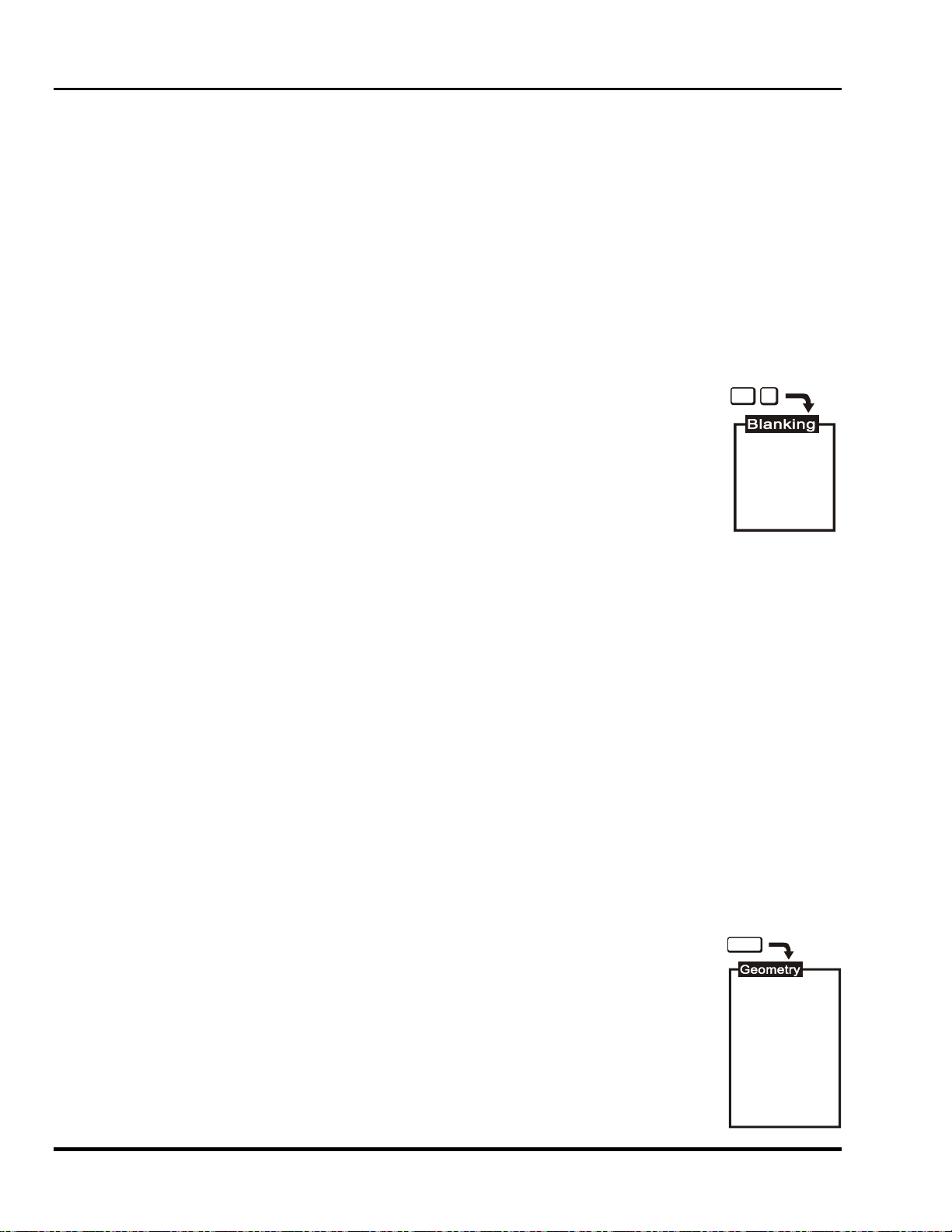
Marquee 8521 Ultra Green (HUD) User's Manual
3.4.2.3 Focus [PIC] [ 4 ]
The Focus function is used to adjust the electrical focus of the combined red, green, and blue color components.
To adjust focus, select Focus from the Picture menu then use [▲] and [▼] until the center of the display appears
the sharpest. If the displayed image cannot be adequately focused, a service adjustment to the electrical focus
may be required or an optical focus adjustment is necessary. Refer to the Section 2.5 for optical focus
instructions.
3.4.2.4 Sync (Fast/Slow) [PIC] [ 5 ]
The Sync function is used to minimize horizontal jittering, "flag waving" or tearing at the top of the display image.
This effect sometimes occurs when the source is a VCR or video signal. The function changes the
synchronization mode of the projector from fast to slow, or slow to fast.
To toggle between fast and slow sync, select item 5 from the Picture menu. Item 5 indicates the current
synchronization mode.
3.4.2.5 Blanking (Top/Bottom/Left/Right) [PIC] [ 6 ]
PIC
The Blanking selection item is used to hide or blank out unwanted information or noise at the
6
top, bottom, left, or right of the display image. Blanking adjustments may be required when the
source is a VCR or video signal.
To adjust blanking, select Blanking from the Picture menu. From the Blanking menu, select
item 1, 2, 3 or 4 to adjust the amount of blanking at the top, bottom, left, or right of the display
(respectively). A blanking slidebar is displayed for each adjustment. A 0% level on the slidebar
indicates no blanking. For top and bottom adjustments, use [▲] and [▼] to adjust the amount of
1. Top
2. Bottom
3. Left
4. Right
blanking. For left and right adjustments, use [◄] and [►] to adjust the amount of blanking.
After completing each adjustment, press [ENTER] to return to the Blanking menu, or press [EXIT] to return to the
picture.
3.4.2.6 Auto Clamp (On/Off) [PIC] [ 7 ]
The Auto Clamp function is used to turn automatic signal clamping on or off. For most input signals, auto clamp
should be on. However, if one or more of the red, green, or blue color components is abnormally bright, turn auto
clamp off. An abnormally bright color component can occur if the input signal contains more than one sync type
(e.g., both sync on green, and composite sync). If you are using a composite video source with ASR and are
connected to an RGB interface, turn the Auto Clamp off.
To toggle auto clamp on or off, select item 7 from the Picture menu. Item 7 indicates the current Auto Clamp
setting.
3.4.2.7 Retrace (Short/Long) [PIC] [ 8 ]
This function is used to set the projector's horizontal retrace time. Retrace time affects the width and display of
the picture. A short retrace time may be required if information is missing or "cut off" at the left or right sides of
the picture. A long retrace time may be desired if the picture is significantly smaller than the raster.
To toggle between short and long retrace, select item 8 from the Picture menu. Item 8 indicates the current
retrace setting.
Note: Check phase, left blanking, and right blanking from the Picture menu before changing retrace time.
Note: Long retrace is not available at all scan frequencies.
3.4.3 Geometry Functions [GEOM]
GEOM
Geometry functions are accessed through the Geometry menu. To display this menu, press
[GEOM].
Note: It is usually easier to adjust display geometry while a test pattern
([ # ]) is displayed.
1. Size
2. Keystone
3. Side Pin
4. Top Pin
5. Bottom Pin
6. Bow
7. C Linearity
8. S Linearity
9. Skew
3-14 Operation
Artisan Technology Group - Quality Instrumentation ... Guaranteed | (888) 88-SOURCE | www.artisantg.com

Section 3
3.4.3.1 Size [GEOM] [ 1 ]
The Size function is used to adjust the horizontal and vertical size of the display image. (This adjustment is also
available through the Picture menu).
To adjust size, select Size from the Geometry menu. Two slidebars are displayed: a Horizontal Size slidebar and
a Vertical Size slidebar. Press [▲]or [▼] to adjust vertical size, and [◄] or [►] to adjust horizontal size until the
objects within your picture have the proper shape. For example, if there is a circle in your picture, size should be
adjusted so that the circle is round, not oval.
Note: The Size function should not be used to compensate for aspect ratio mismatches between source
images and the projection screen. Not all sources use the same aspect ratio therefore it may not
always be possible to fill the entire screen. ("Aspect Ratio" is defined in Appendix A).
3.4.3.2 Keystone [GEOM] [ 2 ]
The Keystone function adjusts side keystone geometry distortion. Adjust keystone to change the width at the top
of the display in relation to the width at the bottom. The displays below
demonstrate keystone adjustment.
To adjust keystone, select Keystone from the Geometry menu then press [◄] or
[►] to adjust the top and bottom widths of the display as desired.
3.4.3.3 Side Pin [GEOM] [ 3 ]
The Side Pincushion function adjusts pincushion of the sides of the display image.
The two displays shown below demonstrate side pincushion adjustment.
To adjust side pincushion, select Side Pin from the Geometry menu then
press [◄] or [►] until the sides of the image are as curved or as straight as
desired.
3.4.3.4 Top [GEOM] [ 4 ]
The Top function adjusts the level (Top Key) and pincushion (Top Pin) of the top
half of the display image. The four displays shown here demonstrate Top
adjustments.
To stretch the upper left or right corner up or down, select Top from the Geometry
menu and press [◄] or [►]. To adjust top pincushion, press [▲] and [▼] until the
top half of the image is as curved or as straight as desired.
3.4.3.5 Bottom [GEOM] [ 5 ]
The Bottom function adjusts the level (Bottom Key) and pincushion (Bottom Pin)
of the bottom half of the display image. The four displays shown at right
demonstrate Bottom adjustments.
To stretch the lower left or right corner up or down, select Bottom from the
Geometry menu and press [◄] or [►]. To adjust bottom pincushion, press [▲]
and [▼] until the bottom half of the image is as curved or as straight as desired.
3.4.3.6 Bow [GEOM] [ 6 ]
The Bow function adjusts horizontal bowing (H Bow) across an image. It also
adjusts vertical curvature (V Bow) in the middle of the picture. The four displays
at right demonstrate H Bow and V Bow adjustments.
To adjust H bow, select Bow from the Geometry menu then press [◄] or [►]
until the image appears as desired. To adjust V Bow, press [▲] and [▼] until
the center of the picture is as curved or as straight as desired.
Display Systems
Artisan Technology Group - Quality Instrumentation ... Guaranteed | (888) 88-SOURCE | www.artisantg.com
3-15
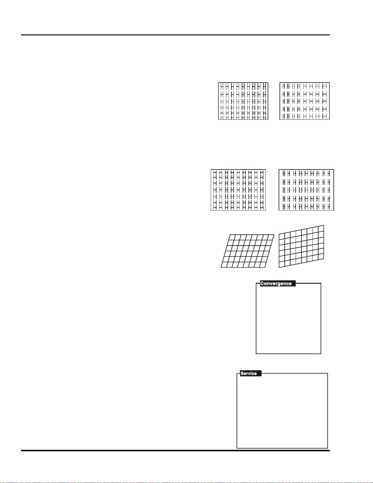
Marquee 8521 Ultra Green (HUD) User's Manual
3.4.3.7 C Linearity [GEOM] [ 7 ]
The C Linearity function corrects for gradual non-linearity between the top and bottom or left and right sides of the
display image. Examples are shown below. In the first example the top of the image increases in vertical size
while the bottom decreases in vertical size. In the second example the right side of the image increases in
horizontal size while the left side decreases in horizontal size.
Select C Linearity from the Geometry menu. It is best to have a screen
full of characters displayed. Or use one of the internal test patterns
available by pressing [ # ]. If there is a vertical non-linearity, press [▲]
and [▼] until the characters at the top, middle, and bottom of the
screen have the same vertical size. If there is a horizontal nonlinearity, press [◄] or [►] until the characters at the left, middle, and
right of the screen have the same horizontal size.
3.4.3.8 S Linearity [GEOM] [ 8 ]
The S Linearity function corrects for vertical and horizontal non-linearity’s which extend from the center of the
display to the top and bottom or left and right. Examples are shown below. Notice how the top and bottom or left
and right characters are much smaller in size than the center characters.
Select S Linearity from the Geometry menu. It is best to have a
screen full of characters displayed. Or use one of the internal test
patterns available by pressing [ # ]. If there is a vertical nonlinearity, press [▲] and [▼] until the characters at the top, middle,
and bottom of the screen have the same vertical size. If there is a
horizontal non-linearity, press [◄] or [►] until the characters at the
left, middle, and right of the screen have the same horizontal size.
3.4.3.9 Skew [GEOM] [ 9 ]
The Skew function adjusts the display image so that the sides of an
image appear to be leaning to one side and/or shifted up or down. The
two displays below demonstrate skew adjustment.
To adjust H Skew, select Skew from the Geometry menu then use [▲]
and [▼] until the image is slanted from side to side as desired.
For V Skew, press [▲] and [▼] to slant up or down.
3.5 Convergence Registration
With three-CRT systems normal convergence registration is the process of aligning
the red, green, and blue color components on the projection screen. The Marquee
8521 Ultra Green (HUD) projector is a single CRT/Lens system, as the name applies
and therefore requires only green geometry correction. Correction settings can also
be saved in Recall memories.
To Perform a Convergence:
Begin by selecting the input source to be converged. Convergence settings will be
saved in the current setup memory. Next, press [CONV] to display the Convergence
menu. Select one of the convergence options from the menu.
[ 5 ]: The Service selection is used to access the convergence service
utilities. These utilities are provided for qualified service personnel only.
(Password access is required).
1. Green Interpolated
2. Green Random Access
3. -
4. -
5. -
6. -
7.-
During adjustments
press <#> to cycle
to internal image.
1. -
2. -
3. -
4. -
5. Service
During adjustments
pres <#> to cycle
to external image.
3-16 Operation
Artisan Technology Group - Quality Instrumentation ... Guaranteed | (888) 88-SOURCE | www.artisantg.com

Section 3
3.5.1 Green Interpolated
The Green Interpolated adjustment allows you to quickly and easily adjust the geometry of the green raster at 45
zones in the image. Zones are accessed in a predetermined order, and like Interpolated Convergence,
adjustments affect more than one zone. To begin Green Interpolated adjustment, press [1] from the
Convergence Service menu. An internally generated green crosshatch is displayed for the alignment. If you
prefer to use the external input, press [#] repeatedly to cycle to the external image.
Initially, a rectangular box surrounds the center zone. When the box is at the center zone, adjustments are
"static" and move the entire raster. Use [▲], [▼], [◄] or [►] to adjust the
position of the image on the screen. Press [ENTER] to move the box to the
next zone and begin dynamic adjustments. After each adjustment press
[ENTER] to move to the next zone. If you need to go back to a previous
zone, press []. Also, the following reset functions are available:
• Press [0] to reset static and dynamic values.
• Press [1] to reset static values only.
• Press [2] to reset dynamic values only.
Once all 45 zones have been set up, or [EXIT] is pressed, an Exit dialog box is displayed. When first displayed,
the cursor is positioned on "Save". Press [ENTER] or [EXIT] to save the new settings; returns to the Service
menu and returns to presentation level. To continue, move the cursor to "Continue Adjust" then press [ENTER]
or [EXIT]. To discard your changes, move the cursor to "No Save" then
press [ENTER] or [EXIT].
3.5.2 Green Random Access
Exit Convergence
Save
Save
No
Continue
Adjust
The Green Random function lets you access and adjust the green geometry at any one of the 45
zones individually in any order. To begin Green Random Access adjustment, press [2] from the
Convergence Service menu. An internally generated green crosshatch is displayed for the
alignment. If you prefer to use the external input, press [#] repeatedly to cycle to the external image.
Initially, a rectangular box surrounds the center zone. When the box is at the center zone,
adjustments are "static" and move the entire raster. Above the
box, "CONV" indicates that the zone is ready for adjustment.
Use [▲], [▼], [◄] or [►] to adjust the position of the image on
the screen.
CONV
To move to another control point, press [ENTER]. The caption
above the box changes to "MOVE". Use the arrow keys to
move to another zone for convergence. Press [ENTER] again
to change the caption to "CONV" and adjust the raster within the
zone using the arrow keys. As with the Green Interpolated
function, the following reset functions are available:
• Press [0] to reset static and dynamic values.
• Press [1] to reset static values only.
• Press [2] to reset dynamic values only.
When adjustment is complete, press [EXIT] to display the Exit
MOVE
dialog box. Press [ENTER] or [EXIT] to save the new settings;
returns to the Service menu and returns to presentation level.
To continue adjustment from where you left off upon exit, move
the cursor to "Continue Adjust" then press [ENTER] or [EXIT].
To discard your changes, select "No Save".
Note: For large scale adjustments to the green raster,
use Green Interpolated first then use Green Random Access to fine tune if required.
Display Systems
Artisan Technology Group - Quality Instrumentation ... Guaranteed | (888) 88-SOURCE | www.artisantg.com
3-17
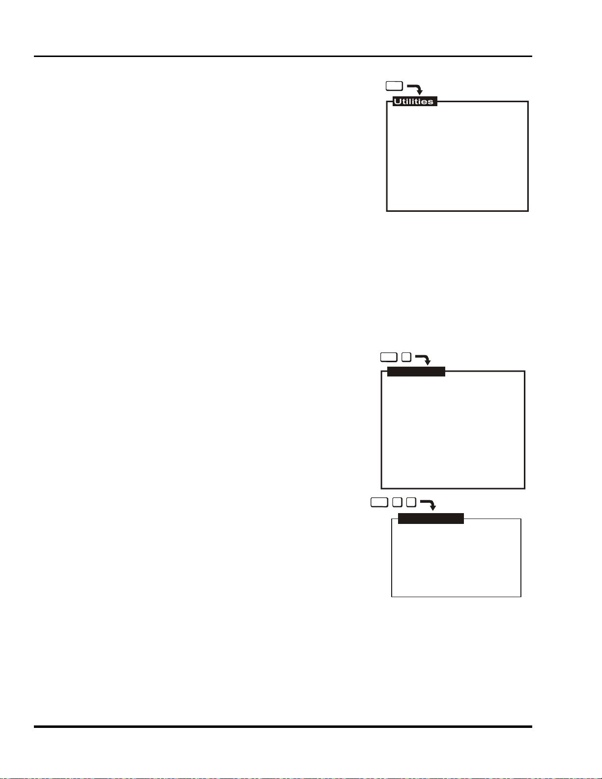
Marquee 8521 Ultra Green (HUD) User's Manual
3.6 Utility Features
The projector's utility features allow you to customize operation of the
projector to suit your application and preferences. To access these features,
press [UTIL]. The Utilities menu is displayed.
Item 1, Source Setup, provides utilities for setup memory
manipulation and selection of internal sources.
Item 2, Channel List, allows you to program the Channel List.
Item 3, Recall Memories, displays a listing of the Recall
memories stored in the projector.
Item 4, Input Memories, displays a listing of the Input memories
stored in the projector.
Item 5, Preferences, lets you set various operational settings which affect the behavior of the
projector, according to your preferences.
Item 6, Remote Control Options, allows you to modify the projector's communication settings for
communication with external control devices such as remote keypads.
Item 7, Clock/Events, allows you to set the projector's real-time clock/calendar and program up to
twelve individual projector control events to be automatically executed at specified times or intervals.
Item 8, N/A
Item 9, Service, provides service utilities for use by authorized service personnel. (Password access
is required.)
3.6.1 Source Setup [UTIL] [1]
Source Setup utilities are accessed by pressing [1] from the Utilities menu.
Six source related utilities are available.
3.6.1.1 Copy Setup [UTIL] [1] [1]
The Copy Setup utility is used to copy stored display settings from one setup
memory to another. When a copy is made, the originating memory remains
unchanged and the destination memory is overwritten with the settings of the
originating memory.
To copy a setup memory, press [1] from the Source Setup menu. A dialog
box is displayed. Enter the setup memory you want to copy from and the
setup memory you want to copy to. Input memories are entered by
pressing [SOURCE] followed by a switcher and slot number. Recall
memories are entered by pressing [RECALL] followed by a two digit Recall
memory number (01 to 99).
Once complete, press [ENTER] to proceed with the copy. A "Copy
Complete" message is briefly displayed to indicate a successful copy.
When you are finished copying setup memories, press [EXIT] to return to
presentation level.
3.6.1.2 ASI with Save [UTIL] [1] [2]
UTIL
1. Source Setup
2. Channel List
3. Recall Memories
4. Input Memories
5. Preferences
6. Remote Control Options
7. Clock / Events
8. -
9. Service
UTIL
1
Source Setup
1. Copy Setup
2. ASI with Save
3. Current Setup: Unlocked
4. ASR: Off
5. Clear Current Setup
6. Select Internal Frequency
Current Setup Memory:
Input:
12
Recall:
01
UTIL
1 1
Copy Setup
Fr om : S 12
To:
R 56
Press <ENTER> to copy
ASI (Automatic Source Interpolation) is a feature which automatically adjusts display settings based on the
settings of other setup memories stored in the projector. The "ASI with Save" utility performs an immediate ASI
on the current source and saves the resulting display settings in the current setup memory. The new settings are
created by either copying the settings from another setup memory which has matching scan frequencies or by
interpolating between "the two closest" setup memories. This feature is very useful when adding a new source to
the system and/or when much adjustment is required. By using the "ASI with Save" feature, the projector can do
most of the required adjustments for you.
3-18 Operation
Artisan Technology Group - Quality Instrumentation ... Guaranteed | (888) 88-SOURCE | www.artisantg.com

Section 3
To perform an "ASI with Save", press [2] from the Source Setup menu. A dialog
box is displayed. Press [◄] to move the cursor bar to "Do It" then press
[ENTER]. New display settings will immediately be calculated and saved in the
current setup memory. The only exception is when the current setup memory is
locked. If locked, display settings will not be modified. If "Cancel" is selected
from the dialog box, the operation is stopped. For more information about the
ASI logic process, refer to Appendix C, ASR/ASI Logic Diagrams.
ASI WITH SAVE
Warning! Current
setup wil be lost.
Do It
Notes about the ASI feature...
ASI works better when there are many setup memories in the system. For example, if you always use the same
input and you never use Recall memories (thus only one setup memory has ever been created), ASI will not be
effective. However, if many Input and Recall memories have been used and adjusted for a variety of sources, the
projector has more "knowledge" in its database for performing an ASI. As this "knowledge" increases, ASI
accuracy improves.
3.6.1.3 Current Setup (Locked/Unlocked) [UTIL] [1] [3]
This utility allows you to lock or unlock the current setup memory. Locking a setup memory prevents changes to
display settings from being saved in that memory. For example, if a locked Recall memory is selected and then
brightness is adjusted, the new brightness setting is only temporary. If the Recall memory is reselected, the
original brightness setting will be restored.
Note: When a locked setup memory is selected, a key icon (
) is displayed in the Source Message.
To lock or unlock the current setup memory, press [3] from the Source Setup menu. Item 3 in the menu indicates
the current setting.
3.6.1.3.1 ASR (On/Off) [UTIL] [1] [4]
The ASR (Automatic Source Recall) feature provides automatic Recall memory selection or ASI (Automatic
Source Interpolation) for inputs which have ASR set to On.
To turn ASR on or off for the current input, press [4] from the Source Setup menu. Item 4 in the menu indicates
the current setting.
When ASR is on, the projector monitors the current input for horizontal and vertical scan frequency changes.
When a frequency change occurs, the current Input memory and all Recall memories are scanned in search of a
memory with matching scan frequencies. If one exists, this memory becomes the current setup memory. If a
matching memory is not found, an ASI is performed. ASI automatically adjusts display settings based on the
settings of other setup memories stored in the projector. The new settings created by ASI are either a copy of the
settings from another setup memory which has matching scan frequencies or an interpolation between "the two
closest" setup memories.
ASR is also performed when:
a) You switch to an input which has ASR set to On.
b) You select a Recall memory and ASR is set to On for the current input.
c) A channel is selected which specifies an input which has ASR set to On.
d) The source frequencies are different than the frequencies in the setup being selected.
When ASR selects a setup memory, a source message is briefly displayed to indicate which memory was
selected. If the new memory settings (Input and Recall) match that of one of the channels in the Channel List, the
matching channel is used and displayed in the source message. Display adjustments, if made, are stored in the
new memory (unless it is locked).
Display Systems
Artisan Technology Group - Quality Instrumentation ... Guaranteed | (888) 88-SOURCE | www.artisantg.com
3-19

Marquee 8521 Ultra Green (HUD) User's Manual
If, on the other hand, an ASI is performed, a source message is briefly displayed which
includes an ASI message to indicate the action taken. If an Input memory with matching
scan frequencies was found by ASI, its settings are used and its identity is displayed. If an
interpolation was performed, the two setup memories selected for the interpolation are
displayed and the resulting settings are used. If adjustments are made to settings created
Input
Recall
by the ASI feature, the new settings will NOT be saved in the current setup memory; a
message is displayed to indicate this. To perform an ASI and have the adjustments saved
in the current setup memory; press [UTIL] [1] [2] to select the ASI with Save utility.
Note: To avoid selection/use of the current Input memory settings when it is desired
Selected
Memory
that Recall memories be ASR selected when a source change occurs, clear the
current Input memory ([UTIL] [1] [2] ) to reset its scan frequency settings to null
values, then immediately lock the memory ( [UTIL] [1] [2] ) so that its settings
cannot be modified.
Input
When to use the ASR feature...
ASI
S05-S06
The ASR feature is intended for use when many different sources must share the same
input (via a third party switcher, for example) or when a signal source can output several
different scan frequencies (e.g., a SVGA card).
Example
A system has six different sources. Source "A" is a video camera. Source "B" is a VCR.
Memories
Selected for
Interpolation
Sources "C" through "F" are various computers. All sources are connected to a 3rd party (non-Electrohome)
signal switcher. The switcher is connected to projector slot 1. For each source, a Recall memory is created to
store its display settings. No two sources have the same frequencies.
01
13
01
[UTIL] [1] [4] is pressed to turn on the ASR feature for the projector's slot 1 input. When ASR is on and a source
is selected by the switcher, the projector automatically adjusts its display settings for the new source by switching
to the Recall memory set up for that source.
3.6.1.3.2 Clear Channel Setup [UTIL] [1] [5]
Clear this
This utility is used to clear the current setup memory to the factory default display
settings.
To clear the current setup memory, press [5] from the Source Setup menu. A dialog box
is displayed. Move the cursor to "Do It" then press [ENTER] to clear the memory. If you
press [ENTER] with the edit cursor on "Cancel", the clear operation is not performed.
When the clear operation is complete, the Source Setup menu is returned.
Note: Note: Clearing a setup memory does not "delete" it from the system. If the projector's 80 memory
spaces are used up, and you need to delete unused memories to make room for new memories, call
your dealer for assistance.
3.6.1.3.3 Select Internal Frequency [UTIL] [1] [6]
UTIL
1
6
This utility allows you to use the projector's internal signal generator. The
internal signal generator is provided to assist users and technicians during
projector setup. By using the internal generator, a setup memory can be
adjusted for a particular set of horizontal and vertical scan frequencies
without requiring an external source. Six preset horizontal and vertical
frequencies are provided.
If one of the preset frequency sets closely match a source you will be using,
you can set up an Input or Recall memory for the source before it is
1.
2.
3.
4.
5.
6.
Horiz
15.73
31.47
47.71
62.50
89.30
126.84
available for connection to the projector. When the source becomes
available, few adjustments will be required. Another reason to use the internal generator is to improve the
accuracy of the ASI feature. By setting up various memories at different scan frequencies, ASI has more
information to choose from when making interpolations between setups.
setup to
defaults.
Do It
Cancel
Vert
59.94
59.94
71.90
66.67
70.00
60.00
To select an internal frequency, press [6], "Select Internal Frequency" from the Source Setup menu. The resulting
menu allows you to choose the scan frequencies of the internal generator. Select one of the displayed items.
3-20 Operation
Artisan Technology Group - Quality Instrumentation ... Guaranteed | (888) 88-SOURCE | www.artisantg.com

Section 3
A
To make a selection, enter an item number or use [▲] and [▼] to move the cursor bar to the item you want then
press [ENTER]. When a selection is made, a crosshatch test pattern is displayed. All subsequent adjustments
are saved in the current setup memory. To select one of the projector's other test patterns, press [#]. Each press
of [#]produces a different test pattern. To return to the current external source, press [EXIT] while only the test
pattern is displayed.
UTIL
3.6.1.3.4 Channel List [UTIL] [2]
The Channel List utility allows you to display and program the projector's
Channel List. The Channel List is a user-programmable list of sources and
projector setups. Sources added to the list can be quickly switched to and
displayed by entering their assigned two-digit channel number. Channels
may also be selected using the keypad's up and down arrow keys.
Channel selection is described in Section 3.2.
To display and/or program the Channel List, press [2] from the Utilities
menu. The initial display shows the first ten channels in the list. Up to 99
channels can be displayed. For each channel a name, input number
(switcher and slot number), Recall memory number, and up/down list may
2
NAME
CH
COMPUTER A
01
COMPUTER B
02
VCR
03
VGA
04
VGA MODE 2
05
06
07
08
09
10
<2 digit no.> or to select channel
to edit selected channel
INPUT
02
14
12
23
23
RECALL
04
01
U/D
be programmed.
Program a channel as follows:
When the Channel List is first displayed, the cursor is positioned in the channel number column. While in the
channel number column, press [▲] or [▼] to highlight the channel you want. Alternatively, you can highlight the
channel you want by entering the channel number on the keypad. Entering the channel number also allows you
to select/display/edit channels beyond the first ten.
Next, press [►] to move the cursor to the Name field. While in the Name column, [▲] and [▼]
change the character at the cursor position and [▲] and [▼] move the position of the cursor.
Once a source name has been entered, move the cursor to the Input field by pressing [ENTER] or
by using [►]. Edit the Input, Recall, and Up/Down (U/D) fields. See below for field definitions. To
.
.
C
B
exit the channel list, press [RECALL] or [EXIT].
space
Note: When the cursor is positioned on an edit field, the field may be cleared by pressing [].
If a channel is selected and ASR is on for the same input, and the incoming frequency does not
match the selected setup memories frequency, it may cause the following: ASR may be triggered,
the setup memory may change and the channel number may be changed to reflect the new
memory.
9
8
7
.
.
Example: If Channel 4 shows input (1,3) and no recall number and input (1,3) switcher 1 slot 3 is selected and
recall memory 55 is currently selected then the Source Message box will show that Channel 4 is selected unless
there is another channel with input (1,3) and recall 55.
The Name Field
The Name field stores the names of the sources in the list. Source names may be up to 11 characters in length.
It is recommended that source names be entered to make it easier to keep track of the sources. Source names
are briefly displayed when channels are selected.
Note: Digits may be entered using the number keys on the keypad or selected using the [▲] and [▼] keys.
Note: If [] is pressed during name editing, all characters in the field to the right of the cursor will be cleared.
The Input Field
The Input field contains the switcher and slot number of the input to be switched to when the channel is selected.
If the input is a direct projector input, the input number is a 0 followed by the projector slot number. If the input is
from a switcher, the input number is a number from 1 to 9 (switcher number) followed by the switcher slot number.
The Recall Memory Field
The Recall Memory field contains the number of the Recall memory to be used when the channel is selected. If
the field does not contain a number (a blank or dash is shown), no Recall memory will be used.
Display Systems
3-21
Artisan Technology Group - Quality Instrumentation ... Guaranteed | (888) 88-SOURCE | www.artisantg.com

Marquee 8521 Ultra Green (HUD) User's Manual
The Up/Down Field (U/D)
The Up/Down field specifies the channels which are accessible when using up/down channel selection (explained
in Section 0). If the field does not contain a check mark, the channel is ignored. To enter a check mark, press a
number key (0-9). To clear a check mark, press [].
Note: Channels should contain valid inputs. For example, do not specify switcher 1 if switcher 1 does not
exist in the system.
3.6.1.4 Recall Memories (Listing) [UTIL] [3]
The Recall Memories utility provides a list of the Recall memories
stored in the projector. (Recall memories are explained in Section
3.3.3). The list includes the scan frequencies of each Recall
memory. A check mark (
) is displayed in the ASR column next
to the memories which ASR may use. If two or more Recall
memories have identical scan frequencies, only the memory last
adjusted will have a check mark.
To list the Recall Memories, press [3] from the Utilities menu. If
more than 30 Recall memories exist, press [ENTER] to display the
remaining memories.
3.6.1.5 Input Memories (Listing) [UTIL] [4]
UTIL
3
Re
Horiz
01
31.50
02
50.80
03
110. 00
04
45.56
05
50.00
06
67.50
07
55.00
08
54.00
09
69.10
10
31.50
11
110. 00
12
94.00
13
96.50
14
54.00
15
28.75
- can be used by ASR.
UTIL
4
Vert
60.00
66.00
71.90
75.00
60.00
70.00
60.00
66.00
71.90
60.00
60.00
70.00
66.00
71.90
75.00
ASR
Re
Horiz
16
105.50
17
93.00
18
43.20
19
24.00
Vert
66.00
83.00
50.00
60.00
ASR
The Input Memories utility provides a list of the Input memories
stored in the projector. (Input memories are explained in Section
3.3). The list includes the scan frequencies of each Input
memory. The ASR column indicates if the ASR feature is on or
off for each memory. A check mark (
) is displayed in the ASR
column next to the memories which may be chosen for use by
In
ASR
02
On
11
Off
13
On
12
On
14
On
Horiz
35.50
110.00
60.00
35.50
38.50
60.00
70.00
66.00
60.00
80.00
Ver t
In
ASR
Horiz
Vert
ASI during an ASR. If two or more Input memories have identical
scan frequencies, only the memory last adjusted will have a
check mark. (ASR is explained in Section 3.6, Utility Features.)
To list the projector’s Input Memories, press [4] from the Utilities
menu. If more than 30 Input memories exist, press [ENTER] to
display the remaining memories.
- can be u sed by ASR/A SI
3.6.1.6 Preferences [UTIL] [5]
The Preferences utility allows you to set various preferences which affect
UTIL
5
the behavior of the projector.
Six preference items are displayed with their current settings. Select an
item to change its setting. (Defaults shown.)
3.6.1.6.1 Auto Power-up (On/Off) [UTIL] [5] [1]
If Auto Power-up is set to On, the projector automatically powers itself up
when line power is removed then re-applied. For example, if power is
1. Auto-Power-up: Off
2. Screen Messages: On
3. Blanking Time: Auto
4. Channel Select: 2 digits
5. Language: English
6. Programmable Events: On
temporarily interrupted due to a storm, the projector will automatically
power back up when power returns. If Auto Power-up were set to Off, the
projector would require a manual power-on.
Note: Upon automatic power-up, the most recent display adjustments may be lost if they were not yet saved
in the current setup memory.
3.6.1.6.2 Screen Messages (On/Off) [UTIL] [5] [2]
The Screen Messages preference allows you to choose whether screen messages will be displayed, such as
slidebars, error and warning messages, the [SOURCE]. [RECALL], [PROJ], and [MUTE] messages, and the
[PIC] and [GEOM] menus. For most applications, it is recommended that Screen Messages be left on. However,
if during a presentation you want to make subtle display adjustments without drawing attention to your actions,
Screen Messages should be set to Off.
3-22 Operation
Artisan Technology Group - Quality Instrumentation ... Guaranteed | (888) 88-SOURCE | www.artisantg.com
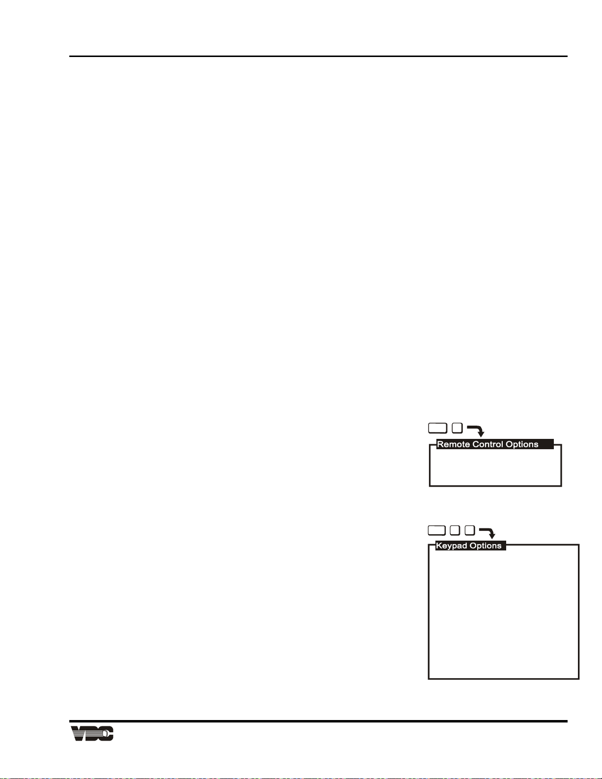
Section 3
Note: It is still possible to display a screen message, such as a slidebar, while Screen Messages is set to
Off. To do this, press [RECALL] just before selecting the function.
3.6.1.6.3 Blanking Time (Auto, 0.5s to 5.0s) [UTIL] [5] [3]
When a source is selected, the projector blanks the screen for a short period of time. You can set the blanking
time to Auto, which allows the projector to determine the best blanking time automatically, or program a particular
blanking time. Time periods from 0.5 second to 5.0 seconds are available. Select the Blanking Time item in the
menu to change its setting.
3.6.1.6.4 Channel Select (1 Digit Only, 2 Digits, 1 or 2 Digits) [UTIL] [5] [4]
There are three different ways the projector can respond to channel numbers entered during direct channel
selection: 1 Digit Only, 2 Digits, and 1 or 2 Digits. Select the Channel Select item in the menu to change its
setting.
"1 Digit Only" allows only one digit to be entered after which the projector switches immediately to the selected
channel. This method can select only channels 1 to 9. "2 Digits" requires two digits to be entered. Both digits
must be entered within 5 seconds. Channel 1 is entered as 01, etc.
"1 or 2 Digits" allows either one or two digits to be entered. If a second digit is not entered within 5 seconds of the
first, the first digit is accepted as the channel number.
3.6.1.6.5 Language (English, French, German, Spanish, Italian) [UTIL] [5] [5]
Menus and text can be displayed in English, French, German, Spanish or Italian. To change the language, select
the Language item in the menu until the desired language is shown.
3.6.1.6.6 Programmable Events (On/Off) [UTIL] [5] [6]
This item allows you to enable or disable the Programmable Events feature. If Programmable Events is set to
On, the events flagged as "ENABLED" in the Programmable Events feature box ([UTIL] [7] [2]) are automatically
executed at the dates and times specified. If Programmable Events is set to Off, programmable event execution
is disabled.
(For information about event programming, refer to the Clock/Events entry in this subsection.)
3.6.2 Remote Control Options [UTIL] [6]
UTIL
6
Remote Control Options allow you to modify the projector's communication
settings for operation with remote keypads and control devices.
To select the Remote Control Options menu, press [6] from the Utilities menu.
Two selection items are displayed: Keypad Options and Communication Setup.
1. Keypad Options
2. Communication Setup
3.6.2.1 Keypad Options [UTIL] [6] [1]
Press [1] from the Remote Control Options menu to display the Keypad Options menu. Use the menu to select
the keypad protocol type the projector will respond.
UTIL
16
3.6.2.1.1 IR Sensor
This setting determines how the projector responds to IR remote keypads
aimed at the projector's built-in IR sensor. Select the IR Sensor menu item to
1. IR Sensor: A or B
2. Remote Jack: A or B
change the current setting. Four settings are available: A or B, A, B, and Off. If
set to A, the projector will only respond if the keypad is set for protocol A
operation. If set to B, the projector will only respond if the keypad is set for
<ENTER> or <no.> cycles
through protocols or Off
protocol B operation. If set to "A or B", the projector will respond to both
protocol settings. If set to Off, the projector will not respond to IR keypad
commands.
The reason for having two protocols available is to allow two projectors in the
same room to be independently controlled by separate remote keypads. See
WARNING:
If both IR sensor and remote
jack are disabled, only the
built-in keypad can be used
to re-enable.
Figure 3-6.
Display Systems
Artisan Technology Group - Quality Instrumentation ... Guaranteed | (888) 88-SOURCE | www.artisantg.com
3-23

Marquee 8521 Ultra Green (HUD) User's Manual
g
.
g
.
Protocol A
IR Keypad
This projector has the
IR Sensor settin
Figure 3-6. Independent IR Keypad Control
CAUTION: The keypad you are using may become inoperative if its protocol does not match its setting in the menu.
!
3.6.2.1.2 Remote Jack
This setting determines how the projector responds to devices connected to the REMOTE jack on the projector's
rear panel. This jack can accept input from a wired keypad or remote IR sensor. Four settings are available:
A or B, A, B, and Off. If set to A, the projector will only respond if the keypad using the REMOTE jack is set for
protocol A operation. If set to B, the projector will only respond if the keypad using the REMOTE jack is set for
protocol B operation. If set to "A or B", the projector will respond to both protocol settings for keypads using the
REMOTE jack. If set to Off, the REMOTE jack is disabled.
3.6.2.2 Communication Setup [UTIL] [6] [2]
Press [2] from the Remote Control Options menu to set the projector identification
number and the RS-232 serial port baud rate.
Projector
This item contains the projector's identification number. The projector's
identification number allows IR remote control of a single projector in a multiprojector installation. To set the projector identification number, select item 1 then
enter a three digit number from 000 to 999. If there is only one projector in the installation, 000 is the
recommended projector number. For more information about multi-projector control, refer to Section 3.7, Multiprojector Functions.
set to "A"
Protocol B
IR Keypad
IR Sensor settin
This projector has the
set to "B"
UTIL
Projector:
Baud Rate:
<no.> to change
26
000
9600
Baud Rate
This item contains the projector's RS-232 serial port baud rate. The RS-232 serial port, located at the back of the
projector, provides a means to control the projector using a computer or another projector. The serial port baud
rate setting must match the operating baud rate of the controlling device. Baud rate may be set to 300, 600,
1200, 2400, 4800, or 9600. To set the baud rate, select item 2 from the menu until the desired baud rate is
displayed.
Note: If unsure of your computer's baud rate setting, refer to the system documentation provided with the
computer.
Note: For information about cable connections between devices, refer to Appendix D.
3.6.2.3 Clock/Events [UTIL] [7]
Clock/Events allows you to set the projector's real-time clock/calendar and program up to twelve individual projector control
events to be automatically executed at specified times or intervals.
To select the Clock/Events menu, press [7] from the Utilities menu. Two selection items are available: Set Clock
and Programmable Events. The current time and date setting is displayed at the bottom of the menu.
3-24 Operation
Artisan Technology Group - Quality Instrumentation ... Guaranteed | (888) 88-SOURCE | www.artisantg.com

Section 3
3.6.2.3.1 Set Clock [UTIL] [7] [1]
Press [1] from the Clock/Events menu to display the Set Clock menu. Use the menu to set the current time and
date and their format.
Time
To edit the time stored in the real time clock/calendar, press [1] from the Set Clock menu. This puts you in time
editing mode. A flashing cursor is positioned at the first digit of the time field. Use the number keys to enter the
current time (hours and minutes), using the format displayed in item 3. For 12 hour format, enter "01" to "12" for
the hours and use [▲] or [▼]to toggle between a.m. and p.m.. For 24 hour format, enter "00" to "23" for the
hours. Enter "00" to "59" for the minutes. When the proper time has been entered and is displayed, press
[ENTER] to accept the changes and leave time editing mode.
Note: On entry of the last digit of minutes, you automatically leave time editing mode
Note: Years from 1990 to 2089 are assumed and handled.
Date
To edit the date stored in the real time clock/calendar, press [2] from the Set Clock menu. This puts you in date
editing mode. A flashing cursor is positioned at the first digit of the date field. Use the number keys to enter the
current date per the format displayed in item 4 (month/day/year, day/month/ year or year/month/day). When the
proper date has been entered and is displayed, press [ENTER] to accept the changes and leave date editing
mode.
Note: On entry of the last digit, you automatically leave date editing mode.
Time Format
Press [3] from the Set Clock menu to change the time display format. The format may be 12 hours (12h) or 24
hours (24h). All references to time by the projector will use the format displayed (this includes the time displayed
in item 1.)
Date Format
Press [4] from the Set Clock menu to change the date display format. The format may be month/day/year
(MM/DD/YY), day/month/year (DD/MM/YY) or year/month/day (YY/MM/DD). All references to date by the
projector will use the format displayed (this includes the date displayed in item 2).
3.6.2.4 Programmable Events [UTIL] [7] [2]
Press [2] from the Clock/Events menu to display the Programmable Events feature box. The Programmable
Events feature box allows you to program a list of up to twelve events to occur at specified times and intervals.
For example, you can program the projector so that at the same time each day, standby mode is turned off and
Source 01 is displayed. See the example below.
Each line contains a type of event, a frequency of occurrence (interval), a start time and an enable/disable flag.
To program or modify an event, first use the arrow keys to move the cursor to the field you want to modify (for
example, the Type field). Next use [ENTER] and/or the number keys to modify that field. Details for field
modification are provided on the following pages. Modify each field in the row as necessary making sure all fields
for the event are valid and logical.
When all modifications have been made, press [EXIT] to display the Exit dialog box. When the Exit box is first
displayed the cursor bar is positioned on "Save". Press [ENTER] or [EXIT] to save the new changes. To return to
the Programmable Events feature box, move the cursor bar to "Continue Change" then press [ENTER]. To
discard your changes, move the cursor bar to "No Save" then press [ENTER] or [EXIT]. [ENTER] returns you to
the Clock/Events menu. [EXIT] returns you to presentation level.
The Type Field
The Type field shows the event to take place. With the cursor positioned on the Type field press [ENTER] to
cycle through the available events. Press [] to clear the entire event line. Events are described in Table 3-1
below.
Display Systems
Artisan Technology Group - Quality Instrumentation ... Guaranteed | (888) 88-SOURCE | www.artisantg.com
3-25

Marquee 8521 Ultra Green (HUD) User's Manual
Table 3-1. Type Field Events
EVENT DESCRIPTION NOTES
None No programmed event.
Standby On Turn Standby mode on.
Standby Off Turn Standby mode off.
Power Off Turn Power off.
channel selection
source selection
ACON (Full) Perform an ACON (full) auto-convergence. ACON option is required.
ACON (Touchup) Perform an ACON (touchup) auto-convergence. ACON option is required.
ACON (Center Only) Perform an ACON (center only) auto-convergence. ACON option is required.
Channels Up Switch to the next available channel from the Channel List. Cycles back to the first channel after last
Channels Down Switch to the prior available channel from the Channel List. Cycles to the last channel after the first
Warm up Perform a warm-up sequence:
Select a channel from the Channel List. * Use the number keys to enter the channel#.
Select an input. * Use the number keys to enter
1. Turn Standby mode off (if on).
2. Set Contrast to 20%, Brightness to 50%, HSize to 80%,
VSize to 80% and master static focus to 100%.
3. Display white field for 15 min.
4. Restore original display settings.
the switcher# & slot#.
channel is selected.
channel is selected.
Exit from warm-up occurs after 15 minutes or
when the EXIT key is pressed. Other keys
which stop warm-up are PROJ, *, UTIL, CONV
and RECALL. When warm-up stops, all
original display settings are restored.
* Only valid entries are accepted.
The Interval Field
The Interval field shows a date or interval at which the event is to take place. With the cursor positioned on the
Interval field press [ENTER] to cycle through the available options. See Table 3-2 below for details.
Table 3-2. Interval Field Options
EVENT
INTERVAL
specific date At a specific calendar date * Use number keys for date entry per the format defined
Daily Every day.
Mon-Fri Monday through Friday.
Sat-Sun Saturday and Sunday.
Mondays Monday.
Tuesdays Tuesday.
Wednesdays Wednesday.
Thursdays Thursday.
Fridays Friday.
Saturdays Saturday.
Sundays Sunday
min./sec. interval Repeatedly at a specified time interval, in minutes
and seconds, starting at the time set in the Start
field. (Applies to Channel Up/Down events only.)
ACTIVATES THE EVENT NOTES
by the Set Clock utility.
* Use the number keys to enter minutes and seconds.
The seconds interval must be an even number, e.g.,
02, 04, 06, etc.
* Only valid entries are accepted.
The Start Field
The Start field shows the start time of the event. With the cursor positioned on the Start field use the number
keys to enter the start time. Use the notation previously defined by the Set Clock utility (12 hour or 24 hour). If
using a 12 hour clock, press [ENTER] to toggle between a.m. and p.m.
Note: Only valid entries are accepted. For example, if "4" is entered as the first digit of the Start time it will
not be accepted. The first digit must be either "0" or "1" when using a 12 hour clock, and "0", "1" or "2"
when using a 24 hour clock.
The Enabled Field
The Enabled field allows you to enable or disable a programmable event. When enabled, the event is performed
as programmed. When disabled, the programmed event is ignored. A check mark indicates that the event is
enabled. With the cursor positioned on the Enabled field press [ENTER] to toggle display of the check mark.
3-26 Operation
Artisan Technology Group - Quality Instrumentation ... Guaranteed | (888) 88-SOURCE | www.artisantg.com

Section 3
General Notes about Programmable Events
• All events are ignored if Programmable Events is set to Off in the Preferences menu ([UTIL] [5]).
• The projector must be turned on for programmable events to take place.
• Be careful not to schedule two events so close to each other such that the second event is scheduled
to begin before the first event is complete; otherwise the second event may be ignored. For example,
do not schedule an event to take place one minute after a full ACON auto-convergence. A full ACON
convergence takes longer than one minute to complete.
• If the projector is not at presentation level when an event is scheduled to begin, that event will be
ignored unless presentation level is returned within the minute that that event is to take place.
• An error or "invalid" message is temporarily displayed at the bottom of the feature box when an entry is
invalid or does not make sense.
• "Error" in an Enabled field indicates an invalid entry for that event.
• Events scheduled at the same time are performed in the order listed in the Programmable Events
feature box. Events never occur simultaneously.
About Channel Up/Down Events...
Channel Up/Down events are handled differently than other events. A Channel Up or Channel Down event is
continuously repeated at the time interval set by the Interval field. The process begins at the start time set by the
Start field. This feature is provided for applications such as surveillance or status display systems where multiple
sources are sharing one projection display. For example, a bus terminal may use this feature to display a number
of different bus schedules, each displayed for ten seconds at a time.
To use this feature, a number of video sources must be fed to the projector or a connected switcher. Each source
is assigned to a channel in the Channel List. The U/D status of each of these channels must be enabled in the list
- see the Channel List entry in this section for details. Within the Programmable Events feature box, the event
type is set to Channel Up or Channel Down. The interval and start time is entered and the event is enabled by
setting a check mark in the Enabled field. When the event is enabled and the start time is reached, the projector
begins cycling through the enabled channels in the Channel List. Each channel-defined source is displayed for
the set interval period then the next lower or higher channel enabled in the Channel List is displayed. This
continues until the event is disabled or the projector is turned off.
Note: If during Channel Up/Down cycling you press a key to make an adjustment or change a projector
setting, the channel cycling process pauses until you return to presentation level. If you manually
select a different channel, channel cycling will resume from that channel.
3.7 Multi-projector Functions
In a multi-projector installation it is usually desired to have a single IR keypad control all the projectors in the
system. This section explains the special control functions available for such installations.
3.7.1 The Projector
The Projector function allows you to select which projector in a group will respond to IR keypad commands. To
use this function, each projector in the installation must first be assigned a unique projector number. Projector
numbers are assigned through the Communication Setup menu which is accessed by pressing [UTIL] [6] [2] on a
built-in keypad or a wired remote keypad. Once each projector has its own unique projector number, projectors in
the installation can be individually controlled using the same IR keypad.
To select a projector to solely respond to commands from an IR keypad, press [PROJ] followed by the projector's
identity number. The specified projector will be the only projector which will respond to the keypad.
To enable ALL projectors to listen to the IR keypad, press [PROJ] []
Display Systems
Artisan Technology Group - Quality Instrumentation ... Guaranteed | (888) 88-SOURCE | www.artisantg.com
3-27

Marquee 8521 Ultra Green (HUD) User's Manual
This Page Intentionally Left Blank
3-28 Operation
Artisan Technology Group - Quality Instrumentation ... Guaranteed | (888) 88-SOURCE | www.artisantg.com

Section 4 Maintenance
4.1 Warnings and Guidelines
The Marquee projection system is CSA approved and is designed for safe and reliable operation. However, safe
operation cannot simply be assured by design; installers, maintainers, and users must maintain a safe operating
environment for the system. This section covers warnings and guidelines which promote the safe usage of the
projector. Please read through and understand these warnings and guidelines.
4.1.1 Labels and Markings
Observe and follow all warnings and instructions marked on the projector.
The exclamation point within the equilateral triangle is intended to alert the user to the presence
of important operating and maintenance (servicing) instructions in the literature accompanying
the projector.
The lightning flash with arrowhead symbol, within the equilateral triangle is intended to alert the
user to the presence of uninsulated "dangerous voltage" within the projector's enclosure that may
be of sufficient magnitude to constitute a risk of electric shock to persons.
4.1.2 Projector Location
Operate the projector in an environment which meets the operating range specifications in the specifications. Do
not operate the projector close to water ─ for example, near a swimming pool.
Do not place the projector on an unstable cart, stand or table. If the projector is to be ceiling
mounted, only use an VDC Display Systems approved ceiling mount fixture.
The projector and cart combination should be used with care. Quick stops, excessive force,
and uneven surfaces may cause the projector and cart combination to overturn.
4.1.3 Power Cord and Attachments
Only use attachments or accessories recommended by VDC Display Systems. Use of others may result in the
risk of fire, shock or personal injury.
Do not allow anything to rest on the power cord. Locate the projector where the cord cannot be abused by
persons walking on it or objects rolling over it.
Operate the projector at the voltage indicated on the line voltage indicator. Do not overload power outlets and
extension cords as this can result in fire or shock hazards.
The projector is equipped with a three wire plug having a third (grounding) pin. This is a safety feature. If you are
unable to insert the plug into the outlet, contact an electrician to have the outlet replaced. Do not defeat the
safety purpose of the grounding-type plug.
4.1.4 Ventilation Slots
Slots and openings in the projector provide ventilation. To ensure reliable operation of the projector and to
prevent overheating, these openings must never be blocked or covered. The projector should never be placed
near or over a radiator or heat register. The projector should not be placed in an enclosure unless proper
ventilation is provided.
Do not push objects of any kind into the projector through the ventilation openings. They may touch dangerous
voltages or short-out parts resulting in a fire or shock hazard. Do not spill liquids of any kind into the projector.
Should an accidental spill occur, immediately unplug the projector and have it serviced by a qualified service
technician.
Display Systems
Artisan Technology Group - Quality Instrumentation ... Guaranteed | (888) 88-SOURCE | www.artisantg.com
4-1
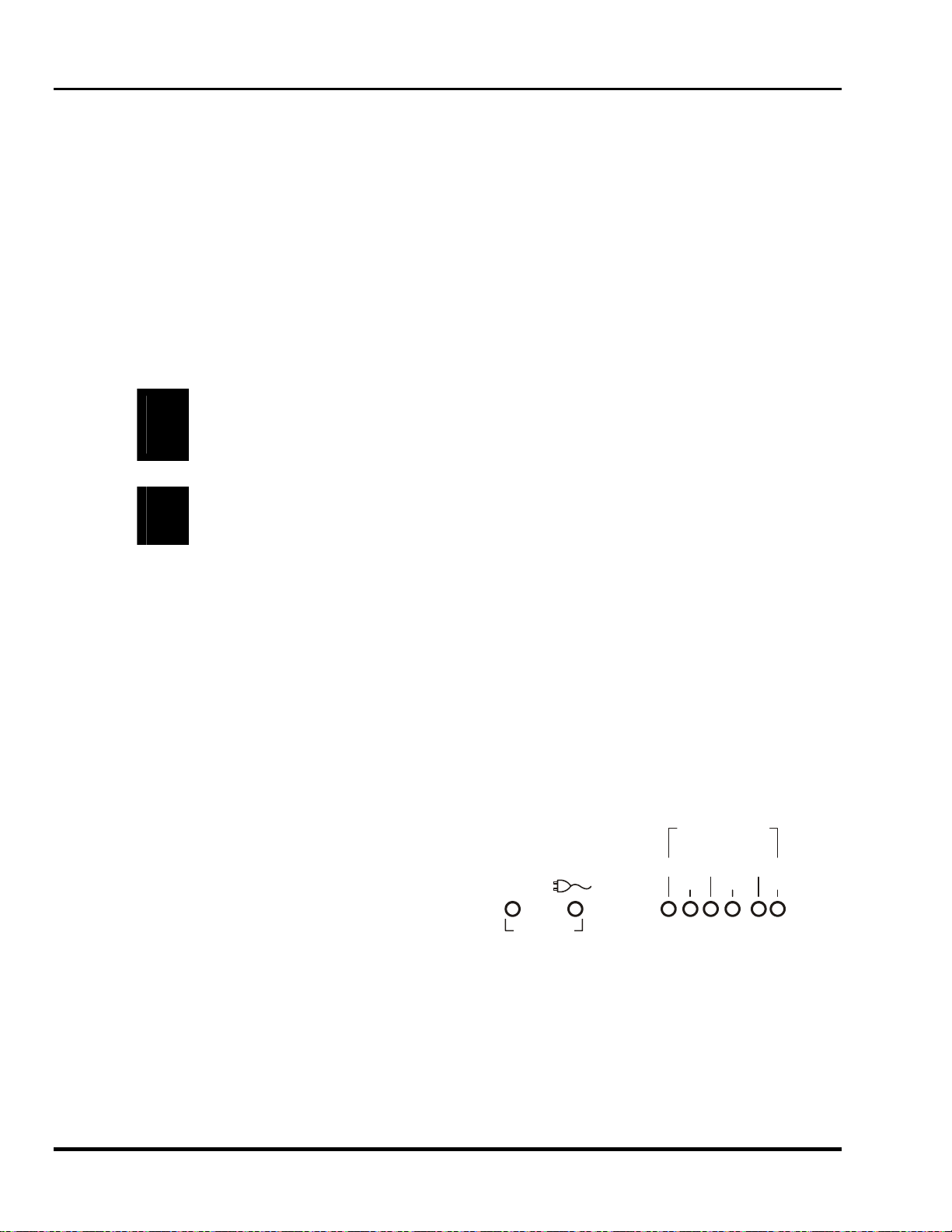
Marquee 8521 Ultra Green (HUD) User's Manual
4.1.5 Servicing
If any of the following conditions exist, unplug the projector from the power outlet and refer service to qualified
service personnel.
• The power cord has been damaged.
• Liquid has been spilled into the projector.
• The projector has been exposed to excessive moisture.
• The projector does not operate normally.
• The projector has been dropped or the case has been damaged.
• Projector performance has deteriorated.
Do not attempt to service the projector yourself. All servicing must be performed by a qualified VDC Display
Systems service technician. If replacement parts are required, it is important that only VDC Display Systems
approved parts are used. Other parts may result in fire, electric shock or risk of personal injury.
WARNING: THE PROJECTOR IS INTERNALLY SHIELDED TO PROTECT THE
USER FROM EXPOSURE TO SOFT X-RAY RADIATION. IMPROPER SERVICING
!
OR SHIELD REMOVAL MAY RESULT IN PERSONAL INJURY.
CAUTION: In rare instances, flashing lights can trigger an epileptic seizure. During
!
ACON usage persons with epilepsy should look away from the screen.
4.2 Cleaning
Clean the projector when required. Before cleaning, always unplug the projector from the power outlet.
4.2.1 Lens Cleaning
To avoid the risk of scratching the lenses, only clean the lenses if absolutely required. A small amount of dust on
the lenses will have very little effect on picture quality. If the lenses must be cleaned, use a DRY soft cotton cloth.
Rub gently in a circular motion.
4.2.2 Case Cleaning
Clean the case with a soft dampened cloth. Use a mild commercial cleaner. Do not use liquid or aerosol
cleaners.
4.3 Trouble-shooting
If the projector is not operating properly, note the
symptoms of the problem and use the following
guide to assist you. If you cannot resolve the
problem yourself, contact your dealer for assistance.
POWER
0
1
STANDBY
Figure 4-1. Rear Panel LEDs
DIAGNOSTICS
ERROR EHT
V.FAI L
H.FAIL
CLVPS
4-2 Maintenance
Artisan Technology Group - Quality Instrumentation ... Guaranteed | (888) 88-SOURCE | www.artisantg.com

Section 4
4.3.1 Projector Response Problems
Refer to the following if the projector is not responding to keypad commands.
Symptom:
The projector will not turn on when [POWER] is pressed. All back panel lights are off. See Figure
4-1.
Cause/Remedy:
1. The power cord may be disconnected. Check the power cord connection at the wall outlet
and the projector.
Symptom:
The projector will not turn on when [POWER] is pressed. Only the amber
panel is lit.
Cause/Remedy:
1. [POWER] may not have been held down long enough to initiate projector power-up. Hold
2. If using an IR keypad, ensure it is pointed at the screen or the front of the projector. If the
3. If using an IR keypad, the batteries may need replacement. Remove the batteries from the
4. The keypad may be damaged. If the back panel C LED does not flash when [POWER] is
5. If using a remote keypad (IR or wired), the keypad's protocol (A or B) might not match the
Symptom:
The projector will not turn on when [POWER] is pressed. One or more of the following red LEDs are
lit: ERROR, LVPS, EHT, H.FAIL, V.FAIL.
LED on the back
down [POWER] for at least one second to initiate power-up.
keypad is configured for built-in or wired usage, make sure it is properly connected to the
projector.
battery compartment on the back side of the keypad. Install new batteries as described in the
Section 0.
pressed, the projector is not responding to the keypad. Try using a different keypad.
projector's IR protocol setting. Refer to Section 0 for instructions on how to check and
change the keypad's protocol setting. However, if the projector's setting is "Off", the remote
keypad will not respond. You may have to configure the keypad for built-in operation to gain
control of the projector.
Cause/Remedy:
1. An internal failure has occurred. Projector servicing may be required. Contact your reseller
Symptom:
The projector's green POWER LED is lit and all other LEDs are off yet no picture is displayed.
Cause/Remedy:
1. Contrast or brightness may be set too low. Press []to activate the status screen. If there is
2. The room lighting may be too bright.
3. The projector may be too far from the screen. Move the projector closer to the screen. The
4. Were the lens covers accidentally left on? Remove the lens covers.
Display Systems
Artisan Technology Group - Quality Instrumentation ... Guaranteed | (888) 88-SOURCE | www.artisantg.com
or VDC Display Systems for assistance.
no display, press []then increase contrast ([CONT] ) and brightness ([BRITE]) until the
crosshatch is displayed. Adjust contrast and brightness to their proper settings.
maximum throw distance is 25 feet.
4-3

Marquee 8521 Ultra Green (HUD) User's Manual
Symptom:
While in use, the projector suddenly become non-responsive to keypad commands, even when using
a built-in keypad.
Cause/Remedy:
1. Although rare, it is possible that an internal software error occurred which has put the
software in a non-ending loop. This might occur if a power spike interfered with the
projector's internal processor system. To fix this problem, leave the projector plugged in and
using a small screw driver or ball point pen, press the recessed RESET button on the back
panel. This operation will reset the projector's processor without affecting memories or
display settings.
Symptom:
The projector does not respond to the [STBY] or [MUTE] keys.
Cause/Remedy:
1. You may not be holding down the key long enough to initiate the action. Like [POWER],
[STBY] and [MUTE] must be pressed down for at least one second.
Symptom:
The projector does not respond to an IR Remote keypad.
Cause/Remedy:
1. The projector's IR keypad listening status may be turned off. Press [PROJ] []to turn on the
2. The keypad's protocol (A or B) might not match the projector's IR protocol setting. Refer to
3. The IR keypad may be too far away from the projector or screen. Use the IR keypad closer
4. The viewing path between the IR keypad and the projector (or screen or switcher) may be
5. The sensor may be disabled per the Keypad Options menu ([UTIL] [6] [1]).
6. The batteries in the IR keypad may be weak. Replace the batteries in the keypad. See
7. There may be unusual lighting conditions in the room which effect IR keypad operation.
Symptom:
The display is jittery or unstable.
Cause/Remedy:
listening status of all projectors, or press [PROJ] followed by the projector's identity number
to turn on the listening status of the projector you want to respond.
Section Error! Reference source not found. for instructions on how to check and change
the keypad's protocol setting. However, if the projector's setting is "Off", the remote keypad
will not respond. You may have to configure the keypad for built-in operation to gain control
of the projector.
to the projector or screen. Also ensure the keypad is pointed directly at the screen or the
front of the projector.
restricted. Ensure there is a clear line-of-sight between the keypad and the projector (or
screen or switcher).
Section 1.1.1 for battery installation instructions.
Determine if such conditions exist and correct.
1. The horizontal or vertical scan frequency of the input signal may be out of range. Check the
specifications in Section 1 for scan frequency ranges.
2. Synchronization signals from the source may be inadequate. Correct the source problem.
3. The input signal type may not match the signal type required by the input module. Install the
correct input module/interface to match the signal type of the source.
4-4 Maintenance
Artisan Technology Group - Quality Instrumentation ... Guaranteed | (888) 88-SOURCE | www.artisantg.com

Section 4
Symptom:
The upper portion of the display is waving, tearing, or jittering.
Cause/Remedy:
1. This sometimes occurs when the source is a VCR or video signal. Change the sync mode by
selecting the fast/slow sync option from the Picture Adjust menu ([PIC] [5]).
Symptom:
The upper or lower portions of the display are cut off.
Cause/Remedy:
1. A top or bottom blanking adjustment may be required. Select the appropriate blanking
adjustment option from the Picture Adjust Menu ([PIC]) then adjust the amount of blanking.
Note: A 0% slidebar level indicates no blanking.
2. A phase adjustment may be required. Select Phase from the Picture Adjust menu ([PIC]).
Adjust phase so that the entire picture is visible and centered.
Symptom:
One side of the display is cut off.
Cause/Remedy:
1. A left or right blanking adjustment may be required. Select the appropriate blanking
adjustment option from the Picture Adjust menu ([PIC]) then adjust the amount of blanking. A
0% slidebar level indicates no blanking.
2. A phase adjustment may be required. Select Phase from the Picture Adjust menu ([PIC]).
Adjust phase so that the entire picture is visible and centered.
3. The retrace time of the projector may be longer than the horizontal blanking time of the
signal. Press [UTIL] [1] [8] to change projector retrace time to Short.
Symptom:
Transitions between colors are fuzzy.
Cause/Remedy:
1. Convergence may require adjustment. Perform a convergence on the selected source.
2. The projector may not be optically aligned for the installation. Has the throw distance
changed significantly since the last optical alignment? If so, have the projector re-aligned.
Refer to Section 2.5..
Symptom:
The display is very faint.
Cause/Remedy:
1. Contrast or brightness settings may be set too low.
2. The projection room may be too bright. Lower the intensity of projection room lighting. Reduce light
reflections as much as possible.
3. The projection room walls and ceilings may be too reflective. Reflective ceilings, walls, and floors
should be kept to a minimum. The best projection rooms are dark with matte finishing.
4. The projector may be too far from the screen.
5. The location of the audience with respect to the screen may not be adequate. Make sure the
audience is within the viewing angle set by the projector and screen position, and the screen type.
6. The phase setting may require adjustment. Select Phase from the Picture Adjust menu ([PIC]) then
determine if adjustment improves the display.
7. The source may be double terminated. Ensure the source is terminated (75Ω) only once.
Display Systems
Artisan Technology Group - Quality Instrumentation ... Guaranteed | (888) 88-SOURCE | www.artisantg.com
4-5

Marquee 8521 Ultra Green (HUD) User's Manual
Symptom:
The display appears to be folded.
Cause/Remedy:
1. The phase setting may require adjustment. Select Phase from the Picture Adjust menu
([PIC]) then determine if adjusting the phase improves the display.
Symptom:
The display is reversed or upside down.
Cause/Remedy:
1. The projector scan configuration is not set correctly for the installation type.
Symptom:
The display is not sharp or "clean".
Cause/Remedy:
1. Display adjustment may be required. Adjust the brightness, contrast, focus, and detail
settings.
2. Is a BNC T connector being used? Use a distribution amplifier to boost signal levels.
3. Is the input signal properly terminated?
4. The screen size may be too large. As screen size increases, magnification increases which
reduces brightness. This then reduces the contrast ratio which affects legibility. Sharp
defined edges become soft and fuzzy.
5. The source input signal may be of low quality.
Symptom:
Display quality seems to drift (from good to bad, bad to good, etc.).
Cause/Remedy:
1. The operating temperature of the projector may not be constant. Is the projector close to
2. The source input signal may be of low quality.
3. The horizontal or vertical frequency of the input may have changed at the source end. For
Symptom:
Colors on the display are not accurate (when using the Marquee Multi-standard Decoder).
Cause/Remedy:
1. Color and tint settings may require adjustment.
Symptom:
The display is not rectangular in shape.
Cause/Remedy:
heating and/or air conditioning vents? The ambient temperature after warm-up should be
kept constant below 35 EC (95 EF). Make sure none of the projector ventilation slots are
obstructed.
the selected source, set ASR to on. The projector will then try to use display parameter
settings which are best matched for the source.
1. The geometry settings may not be set correctly. Adjust the display geometry settings. (Press
[GEOM] for the Geometry menu).
4-6 Maintenance
Artisan Technology Group - Quality Instrumentation ... Guaranteed | (888) 88-SOURCE | www.artisantg.com

Section 4
Symptom:
The display is "noisy".
Cause/Remedy:
1. The input may not be terminated. Make sure the input is terminated (75Ω). If it is the last
connection in a loop-through chain, it should be terminated at the projector (only).
2. The signal cables carrying the input signal may be of poor quality. Use only good quality
signal cables. VDC Display Systems cables are recommended.
3. The distance between the input source device and the projector may be too great. If the
distance between the input source device and the projector is greater than 25 feet, signal
amplification/conditioning may be required.
4. There may be interference from other equipment. Keep the projector away from devices
which radiate electromagnetic energy such as motors and transformers. Common sources of
these are slide projectors, speakers, power amplifiers, elevators, etc. Keep 35 mm slide
projectors at least 2 feet away from the projector.
5. The input signal may be of poor quality.
6. If the source is a VCR or off-air broadcast, detail may be set too high
Symptom:
Modified display settings are not being saved in the active setup memory.
Cause/Remedy:
1. Is the active setup memory locked? Press [SOURCE] to display the Source Message. If a
2. ASR is set to On for the current input memory and an ASI was automatically performed due
Symptom:
The display is OK when displaying the crosshatch test pattern ([]) or status screen ([]) but when
trying to display a source, nothing is visible.
Cause/Remedy:
1. You may not be selecting the source correctly. Refer to Section 3.2, for source selection
2. The source may not be connected properly. Verify that the input source is active and check
is displayed, unlock the setup. (Press [UTIL] [1] [3])
to mismatched scan frequencies.
instructions.
the cables between the source and the projector.
Display Systems
Artisan Technology Group - Quality Instrumentation ... Guaranteed | (888) 88-SOURCE | www.artisantg.com
4-7

Marquee 8521 Ultra Green (HUD) User's Manual
This Page Intentionally Left Blank
4-8 Maintenance
Artisan Technology Group - Quality Instrumentation ... Guaranteed | (888) 88-SOURCE | www.artisantg.com
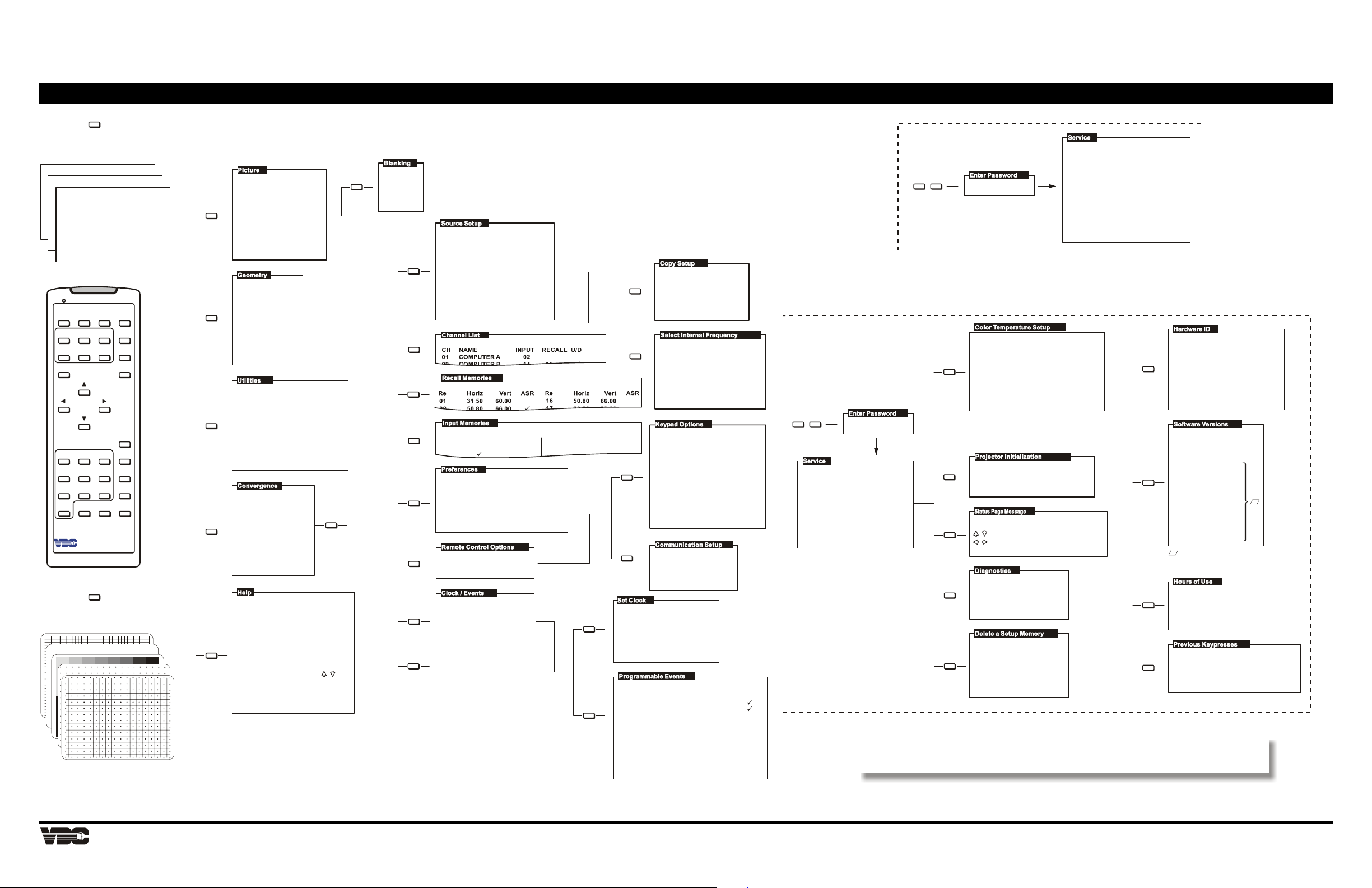
X
X
X
X
X
X
X
Status Pages
Current Display Settings
VDC Display Systems
Marquee XXXX
Projector No:
IR Sensor:
Remote Jack:
Auto Power-up:
Messages:
PROJ UTIL
COLOR
CONT
BRITE
ENTER
1 2 3 RECALL
4
7
0MUTESTBY
Display Systems
Test Patterns
*
Current Input Parameters
Serial No:
000
Software :
A
A
Off
Off
Horiz Scan:
Off
Vert Scan :
Off
Mute:
*
TINT
5
8
Switchers:
Options:
PIC
GEOM
DETAIL
CONV
VOL
EXIT
SOURCE
HELP
6
9
#
POWER
#
XXXXXXX
VX.X
Normal
Normal
1
Decoder
PIC
GEOM
UTIL
CONV
HELP
1. Phase
2. Size
3. -
4. Focus
5. Sync: Slow
6. Blanking
7. Auto Clamp: Off
8. Retrace: Long
9. -
1. Size
2. Keystone
3. Side Pin
4. Top
5. Bottom
6. Bow
7. C Linearity
8. S Linearity
9. Skew
1. Source Setup
2. Channel List
3. Recall Memories
4. Input Memories
5. Preferences
6. Rem ote Contro l Options
7. Clock / Events
8. -
9. Service
1. -
2. -
3. -
4. -
5. Service
During adjustments
pres <#> to cycle
to external image.
1. Guided Source Setup
2. Guided Mechanical Setup
3. Source Selection Guide
4. Keypad Guide
5. -
6. Using Help
For all menus:
Press a number or us e
then <ENTER> to select item.
<HELP> for assistance
<RECALL> to go back one level
<EXIT> to return to picture
see Convergence
Service
Appendix A Menu Tree
Convergence Service
1. Green Interpolated
2. Green Random Access
3. -
1. Top
6
2. Bottom
3. Left
4. Right
1. Copy Setup
2. ASI with Save
3. Current Setup: Unlocked
4. ASR: Off
1
5. Clear Current Setup
6. Select Internal Frequency
Current Setup Memory:
Input : 00
Recall: 00
From:
1
1
To:
Press <ENTER> to copy
S 1 2
R 5 6
CONV 5
XXXX
Utilities Service
2
3
4
In
ASR
0
On
1
Off
1. Auto Power-up: Off
2. Screen Messages: On
5
3. Blanking Time: Auto
4. Channel Select: 2 digits
5
5. Language: English
6. Programmable Events: On
6
1. Keypad Options
2. Communication Setup
1. Set Clock
7
2. Programmable Events
Time: 12 :34 p.m.
Date: 09/29/95
9
see Utilities Service
35.50
31.50
Ver t
60.00
60.00
InHoriz
ASR
Horiz
1
6
Ver t
1
2
1. Time: 12:34 p.m.
2. Date: 09/29/95
3. Time Format: 12h
4. Date Format: MM/DD/YY
TYPE
Standby Off
2
S 01
Channel 69
S 12
None
None
None
None
None
Horiz.
15.73
1.
31.47
2.
47.71
3.
62.50
4.
—
5.
—
6.
1. IR Sensor: A or B
2. Remote Jack: A or B
<ENTER> or <no.> cycles
through protocols or Off
WARNING:
If both IR sensor and remote
jack are disabled, only the
built-in keypad can be used
to re-enable.
Projector: 000
Baud Rate: 9600
INTERVAL START ENABLED
Mon-Fri
Mon-Fri
Daily
09/29/95
Vert .
59.94
59.94
71.90
66.67
—
—
07:30a.m.
07:31a.m.
08:00a.m.
07:40p.m.
UTIL 9
1. Color Temperature Setup
2. Green Focus Adjustment
3. -
4. Projector Initialization
5. Status Page Message
6. Diagnostics
7. Stigmator Adjustment
8. Delete a Setup Memory
9. -
XXXX
D
MARQUEE 8521 Ultra Green (HUD) PROJECTOR MENU TREE
<ENTER> to change event type
1. -
2. -
3. -
4. -
1
5. Contrast Modulation
6. Adjust G-2
During adjustments, press <#>
to cycle to external image.
4
1. Remove All Recall Memories
2. Remove All Memories
3. Reset Everything
Marquee Dealer XYZ
5
to change character at cursor
to move cursor
<ENTER> to save
1. Hardware ID
6
2. Software Versions
3. Hours of Use
4. Previous Keypresses
Enter memory to be
deleted:
8
R 0 4
Press <ENTER> to delet e
Software Version 1.0
4. -
5. -
6. -
7.-
During adjustments
press <#> to cycle
to internal image.
CLM
XXXXXXXXXXXXXX
XXXXXXXXXXXXXX
DPB
HDM
1
Decoder
CLM (U35)
CLM (U16)
DPB (U7)
Switcher 1
Switcher 2
2
Switcher 3
Switcher 4
Switcher 5
Switcher 6
Switcher 7
Switcher 8
Switcher 9
ACON (U8)
F
- "N/A" if switcher not
connected. "N/A" if
ACON not installed.
3
4
# Key Count # Key Count
XXXXXXXXXXXXXX
SWB
XXXXXXXXXXXXXX
CMM
XXXXXXXXXXXXXX
XXXXXXXXXXXXXX
ACON
XXXXXXXXXXXXXX
With CRTs On:
In Standby:
VX.X
IX.X
DX.X
SX.X
SX.X
SX.X
SX.X
SX.X
SX.X
SX.X
SX.X
SX.X
AX.X
Tota l:
XXXXX
XXXXX
XXXXX
F
_____
Display Systems
A-1
Artisan Technology Group - Quality Instrumentation ... Guaranteed | (888) 88-SOURCE | www.artisantg.com

Marquee 8521 Ultra Green (HUD) User's Manual
This Page Intentionally Left Blank
A-2 Menu Tree
Artisan Technology Group - Quality Instrumentation ... Guaranteed | (888) 88-SOURCE | www.artisantg.com
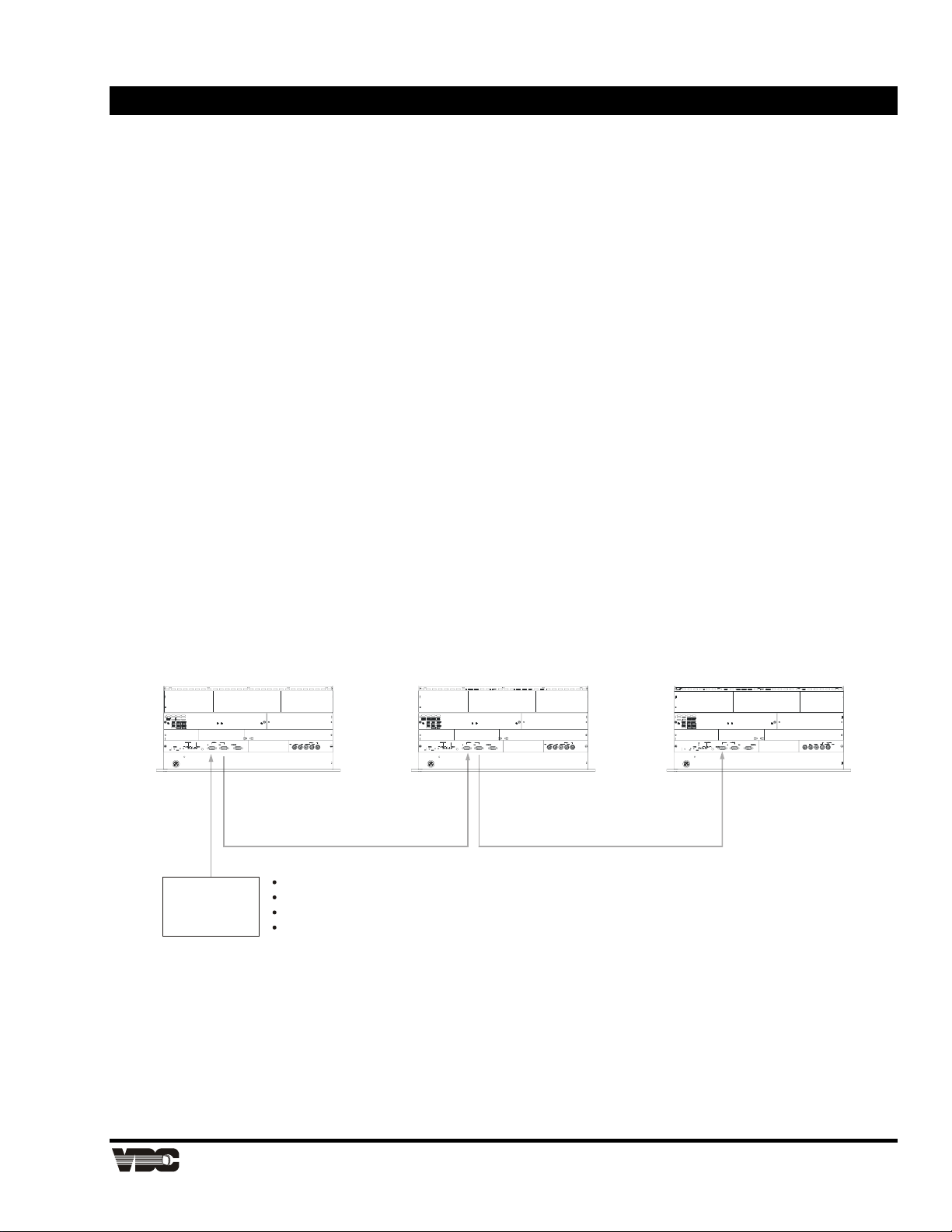
(
)
Appendix B Marquee Projectors RS-232 Control
B.1 Brief History of Marquee RS-232 Communications
Connecting an third party external controller to the RS-232 port on a Marquee projector enables
automated control of individual or multiple projectors according to custom requirements. The original
RS-232 commands enable the controller to be programmed to emulate a projector keypad. The
protocol (message structure) used for issuing these commands remains valid and usable for any
Marquee projector with software version 2.0 or higher. In addition, with software version 4.0 and
higher, you can use a simpler RS-232 protocol to issue these original commands as well as several
other new commands.
Note: This Section is intended for technicians familiar with controller applications and programming. For
highly specialized applications beyond simple projector control, please contact VDC Display Systems
for additional technical assistance.
B.2 System Requirements and Setup
The RS-232 commands in main software V4.0 can be used with any Marquee projector that has the
Control Board #02-2x0336-0xP installed. The software is backwards compatible with existing
Marquee projectors. As shown below, connect the controller only to the “IN” port of the Marquee
projector, never directly to a switcher. Use a quality cable of up to 100 feet in length.
In a typical application, a controller output is connected to the RS-232 “IN” port, and any additional
projectors are networked by connecting the RS-232 “OUT” from one projector to the RS-232 “IN” of
the next as shown below. The controller can then broadcast to all projectors or each individual
projector as desired.
Electronic Chassis
RS-232
RS-232
8 bits
Controller
Figure B-1. Typical RS-232 Control Application
no parity
1 stop bit
9600 baud
default
Electronic Chassis Electronic Chassis
RS-232
Display Systems
Artisan Technology Group - Quality Instrumentation ... Guaranteed | (888) 88-SOURCE | www.artisantg.com
B-1

Marquee 8521 Ultra Green (HUD) User's Manual
S
S
Shield
B.3 RS-232 Communication Cables
B.3.1 RS-232, 9-Pin Male to 9-Pin Female
Step 1. For connection between the projector and a seitcher
Step 2. For connection between projectors
Step 3. For connection to a computer with a 9-pin “AT” type RS-232 port.
(Male - for projector end)
Shielded Multi-conductor Cable
9 Pin D Connector
(Male - for projector end)
9 Pin D Connector
2
Rx
Tx
3
5
hield
Figure B-2. Cable Wiring, RS-232, 9-Pin Male to 9-Pin Female
B.3.2 RS-232, 9-Pin Male to 25 Pin Female
Step 1. Use this cable if the computer's RS-232 serial port uses a 25 pin male D type connector.
Shielded
Multi-conductor Cable
9 Pin D Connector
(Male - for projector end)
22
33
55
Shield
25 Pin D Connector
(Female)
Tx
Rx
hield
2
3
5
2
3
7
Figure B-1. Cable Wiring, RS-232, 9-Pin Male to 25-Pin Female
B-2 Marquee Projectors RS-232 Control
Artisan Technology Group - Quality Instrumentation ... Guaranteed | (888) 88-SOURCE | www.artisantg.com
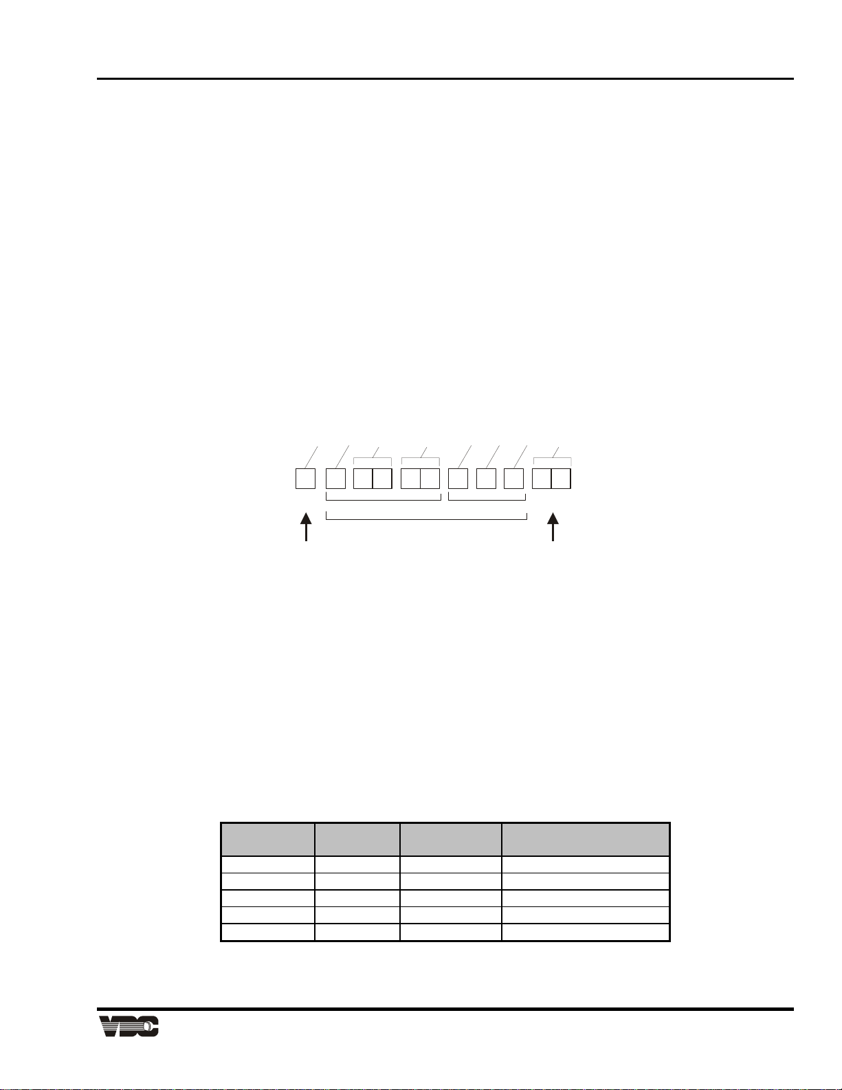
Appendix B
)
)
(
y)
(
y)
B.4 Data Transmission Structure
A basic understanding of RS-232 data transmission structure enables you to begin programming
automated controls for the Marquee projector. Once you have become familiar with this structure,
refer to the two tables later in this document. These tables list the specific binary codes required for
all available commands and provide examples of commands most commonly used in typical
applications. Use these tables to quickly begin programming the controller without having to
determine each complete data stream yourself.
Every Marquee serial communication consists of two parts: the transport layer and the message. In
general, information in the transport layer determines how information is passed to and from the
projector and the message contains the specific information being passed. Both parts are shown in
Figure B-2 and are further described below.
Note: Throughout this document a number preceded by a "$" is a hexadecimal value.
e
)
)
s
e
t
y
h
t
b
g
e
g
a
s
s
e
e
g
M
a
s
t
r
s
a
e
t
S
M
2
n
(
e
n
L
o
i
t
a
n
i
t
s
e
D
e
c
r
u
o
S
s
e
t
y
b
2
(
d
l
e
i
F
n
a
m
m
o
C
t
y
b
1
(
e
1
(
d
o
1
#
C
r
d
e
t
e
e
m
m
a
a
r
r
a
a
P
P
)
)
e
e
t
y
b
1
(
2
#
r
e
t
k
c
e
h
n
C
E
l
t
y
a
b
n
o
i
t
e
p
g
o
(
a
s
s
m
e
u
s
M
f
o
d
X
01234 5 6 7 XX
(01)
TRANSPORT
LAYER BYTE
binar
Figure B-2. A Complete RS-232 Data Transmission
HEADER BODY
MESSAGE BYTE
B.5 Transport Layer
Every message must include a transport layer in order to be recognized as a complete RS-232 data
transmission. As shown in Figure B-2, transport code appears at the beginning and end of every RS-
232 communication. A transport layer has three main functions
3. To mark the start and finish of each message.
4. To prevent data overflow.
5. To separate transport layer codes from message data.
Special control codes reserved only for the transport layer are shown in Table B-1.
Table B-1. Transport Layer Special Control Codes
Binary
(Hex) Value
$01 SOH start of header start of message
$0E SO shift out end of message
$13 XOFF transmit off stop transmission
$11 XON transmit on resume transmission
$1B ESC escape next byte has been shifted
Mnemonic Description Function
(00)(0E)
TRANSPORT
LAYER BYTES
binar
:
Display Systems
Artisan Technology Group - Quality Instrumentation ... Guaranteed | (888) 88-SOURCE | www.artisantg.com
B-3

Marquee 8521 Ultra Green (HUD) User's Manual
B.5.1 $01 AND $0E (MESSAGE START AND END)
Use the $01 control code to preface each and every transmission. This byte indicates to a network
receiver that the next byte is the first byte of a new message. Any message which (for some reason)
is partially received prior to the $01 will be discarded.
The $0E control code signifies the end of each and every transmitted message. It signals to the
receiving network software that the message has been completely transmitted.
B.5.2 $13 AND $11 (STOP AND RESUME)
Normally messages can be sent to the projector before processing of earlier messages has been
completed — the projector will just store messages in a buffer until ready to process. However, if a
series of messages is sent it is possible that the projector will not be able to process them as fast as
they are being transmitted and the buffer will become full. If this happens, the projector will
immediately send the $13 (XOFF) code to halt further transmission. This instructs the controller (and
any devices preparing to transmit) to cease transmission within three characters transmission time.
At 9600 baud (the default baud rate), this gives the controller about three milliseconds to respond.
The projector is able to accommodate the receipt of at least three more bytes after it sends $13
(XOFF) — additional bytes may be lost. When the buffer is once again available, the projector will
send a $11 (XON) command to resume transmission.
Note: XON and XOFF controls apply to both directions of communication.
B.5.3 $1B (ESCAPE)
Occasionally a byte within a message may have the same value as one of the special control codes
reserved for the transport layer. If this occurs, $1B must be used to "escape" the byte so that it is not
mistaken for a transport layer control code. “Escape” a byte by inserting an ESC character ( $1B)
into the data stream just ahead of the message byte in question and then adding 128 ( $80) to the
value of the message byte. This effectively sets the MSB (most significant bit) high, moving the value
of the byte out of the range of values reserved for transport control codes.
On the receiving end, the transport layer software recognizes the escape sequence and strips the
$1B (ESC) from the stream. The next data byte will have its MSB reset which restores it back to its
original value.
B.6 Message Format
The other portion of an RS-232 communication is the message itself (see Figure B-2 again). A
message portion is a sequence of up to 64 bytes — always a five-byte header followed by a variable
length body. The header supplies the information needed for routing the messages within the
projector network, and the body contains the specific projector control data. These two message
components are further described below.
B.6.1 HEADER (NETWORK/PROJECTOR ADDRESSING)
The message header consists of three main parts:
1. Message Length: This byte contains a value which declares the length of the message as a
specific number of bytes. Note that message length does not include bytes from the transport
layer.
2. Destination and Return Address (Source) Fields: These fields contain two sixteen-bit
addresses — one for the message destination and one for the source. A breakdown of each
address field is shown in Figure B-3. Note that Near and Far Port Address bits are now
ignored — while it is strongly recommended that these bits be set to “0” to ensure
compatibility with future releases of software, it is not yet mandatory to do so. Bit #14,
however, must be set to 0.
B-4 Marquee Projectors RS-232 Control
Artisan Technology Group - Quality Instrumentation ... Guaranteed | (888) 88-SOURCE | www.artisantg.com

Appendix B
)
1st Byte 2nd Byte
Bit# 15 14 13 12 11 10 9 8 7 6 5 4 3 2 1 0
Network Address
(ignored if broadcast bit is set to “1”)
Set Far Local Port to “0” (ignored
Set Near Local Port to “0” (ignored)
Always set to “0” (reserved)
Set Broadcast bit “1” to broadcast
Figure B-3. Format of Address Field
Set the Broadcast flag to "0" if a specific projector
is to respond, set to "1" if all projectors are to
respond. Always set Bit 14 to "0" and, if at all
possible, set Bits 10, 11, 12 and 13 to “0” as well.
Bits 0 through 9 contain the Network Address.
Possible Network Addresses are shown in Table
B-2 (decimal values shown). For the Destination
Address field, you should use a projector number.
For the Source field, use the network controller
address (note that the value for a projector
number may require an ESC — see Transport
Layer codes, above).
B.6.2 BODY
The body of a message can consist of one or more bytes, depending on the number of details
required to complete the specific command at hand.
The first byte of the message body represents the type of message being issued. There are three
types of messages: a Set message, a Request message, or a Reply message. For example, the
first byte may be “Set Power” (turn the projector on or off) or “Request Channel” (find out what the
channel is) or “Reply with Signal Status” (relay the current channel number). The binary message
codes for each possible command are listed in Table B-3.
Table B-2. Network Address Assignments
Start Finish Device Type
0 999 projector
1000 1009 switcher
1010 1019 ACON
1020 1022 not assigned
1023 1023 network controller
The next byte(s) is the actual hex value for the parameter in question. For example, to set the
volume to “0” this second byte must be “00”. To set it to 64, this byte must be “$40”. Each parameter
(there may be more than one, depending on the command) requires at least one byte in the
message. Refer to Table B-3 for a list of message codes and parameter codes. Examples of entire
specific commands using these codes appear in Table B-4.
Note: Most “Request” messages have no parameter data.
Note: Do not broadcast a Request to more than one projector.
Note: “Set” and “Reply” messages usually have the same data in the same format.
Display Systems
Artisan Technology Group - Quality Instrumentation ... Guaranteed | (888) 88-SOURCE | www.artisantg.com
B-5

Marquee 8521 Ultra Green (HUD) User's Manual
B.6.3 Optional Checksum
It is no longer necessary to calculate and include an eight-bit additive sum as the next-to-last byte in
every data transmission. Note that you must still include the checksum field in each message
stream, but if the value assigned is “$00” the checksum will be ignored. If you still wish to use an
accurate checksum for maximum message security, calculate the checksum value as follows:
1. Take the message before the transport layer bytes have been added.
2. Add the bytes together.
3. Divide the sum by 256 and take the remainder. The remainder value is the checksum.
The receiving projector software collects all of the message bytes as defined in the first byte of the
message, then creates its own checksum value for comparison with the received checksum. If the
values match, the message is considered to have been correctly received—otherwise the message
is discarded.
Note: NOTE: Transport layer bytes including ESC (and the resultant top bit set) are NOT
included in the checksum. See Transport Layer.
B.6.4 Command Codes
Table B-3 4 lists all 1-byte hex command codes now available on the Marquee. The first column
identifies each projector control, with the applicable set/request/reply command codes listed in the
next two columns — one of these codes appears as the first byte after the header in any message.
The fourth column lists any parameters that may apply to the function at hand, with P1 representing
the first parameter of the data sent (such as switcher number), P2 representing the second
parameter of the data sent (such as slot number) and P3 representing the third parameter (such as
vertical frequency). These bytes follow the command code byte. The last column briefly describes
what each “set” command does.
Note: Each parameter allows a limited range of values — these values are shown in Table B-3 in
decimal format.
Note: The projector will convert any out-of-range value to the nearest maximum value allowed.
For example, “set color to 100” will set the color to its maximum value of 63.
Note: Values are treated as unsigned. So -1 in a byte is treated as 255.
B-6 Marquee Projectors RS-232 Control
Artisan Technology Group - Quality Instrumentation ... Guaranteed | (888) 88-SOURCE | www.artisantg.com
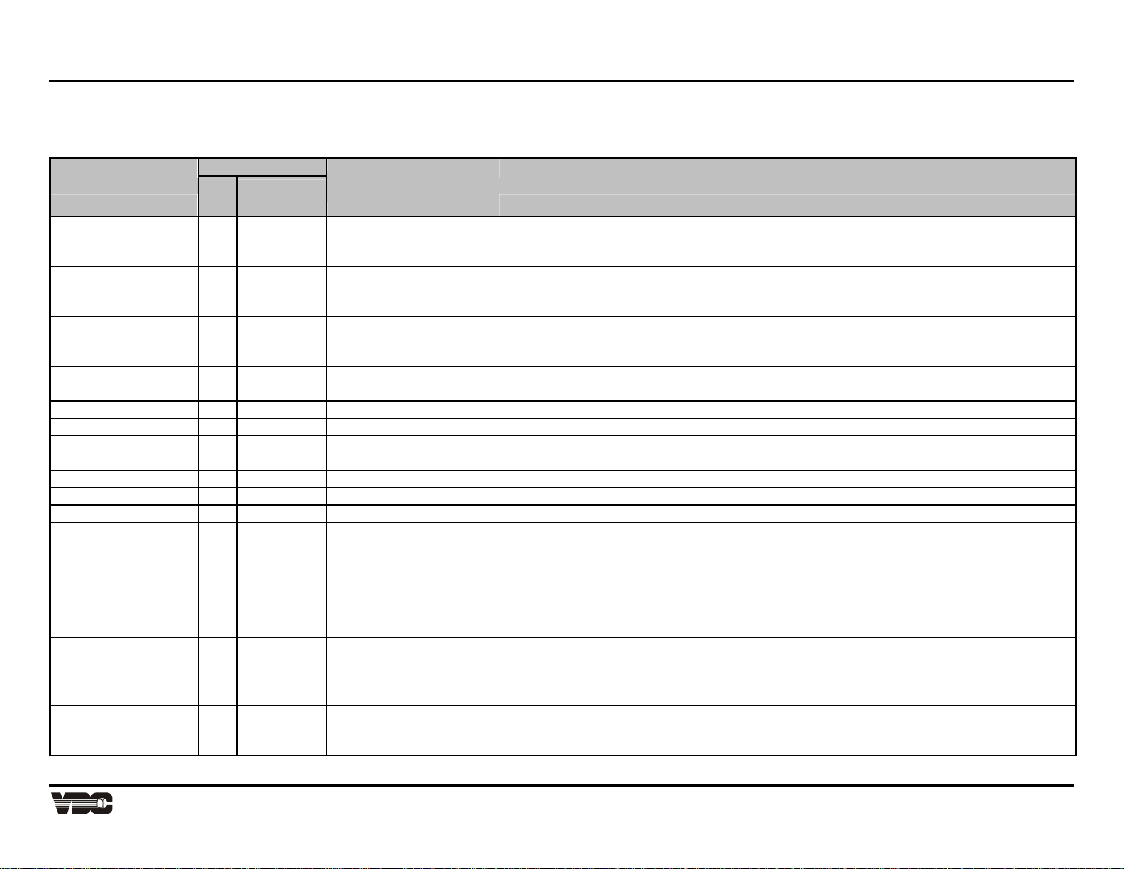
Appendix B
Table B-3. Command Codes and Descriptions
Note: Parameter values are shown in decimal format
Command Code
Function
Set
Request or
Reply
Power ON/OFF $08 $88 P1: 0 = Off
Standby ON/OFF $3D $BD P1: 0 = Off
Parameter(s)
“Set” and “Reply” msg.”
1 = On
2 = Between
1 = On
Description (”set” function)
Turn projector off or on.
NOTE: If “2”, the projector is currently in the process of powering up. In this state, any
RS-232 commands (other than “Power Off” ) will be ignored and discarded.
“On” blanks the picture and mutes the audio (and is same as sending separate commands
to blank picture and mute audio). The projector remains operational while in standby. “Off”
turns picture and audio back on. See page 15.
Picture Mute ON/OFF $0E $8E P1: 0 = Off
1 = On
“On” blanks the picture only — the rest of the projector remains operational. You can go
into this mode, then switch sources or change a setting, and then leave (“Off) to regain the
picture. See page 15.
Audio Mute ON/OFF $0D $8D P1: 0 = Off
Turn the audio off or on. The rest of the projector remains operational.
1 = On
Volume Level $34 $B4 P1: 0-127 Set the volume level of the current slot.
Contrast Level $56 $D6 P1: 0-127 Set the contrast level of the current slot.
Brightness Level $55 $D5 P1: 0-255 Set the brightness level of the current slot.
Color Level $57 $D7 P1: 0-63 Set the color level of the current slot.
Tint Level $58 $D8 P1: 0-63 Set the tint level of the current slot.
Detail Level $59 $D9 P1: 0-63 Set the detail level of the current slot.
Channel ## $0B $8B P1: 1-99 Select channel ##. 0 = no channel
Input (Switcher, Slot) $09 $89 P1 (switcher#): 0-9
P2 (slot#): 1-9
Select input. If P1 = 0 (projector) then:
Slot 1 = standard RGB, VIM
Slot 2 = optional interface card, into VIM
Slot 3 = Composite (on decoder)
Slot 4 = Composite (on decoder)
Slot 5 = S-Video (on decoder)
Slot 6 = S-Video (on decoder)
Recall Memory $0C $8C P1: 0-99 Select recall memory. 0 = none
Internal Frequency $35 $B5 P1: 0-6 Select internal frequency. 0 = current external signal.
1-6 = one of the internal frequencies from the Marquee “Select Internal Frequency” menu.
Key Code $63 n/a P1 = Code Emulate the function of a key on the keypad. Any additional parameters sent are ignored.
See Technical Bulletin TB96-05 (June 1996).
Display Systems
B-7
Artisan Technology Group - Quality Instrumentation ... Guaranteed | (888) 88-SOURCE | www.artisantg.com

Marquee 8521 Ultra Green (HUD) User's Manual
Command Code
Function
Set
Request or
Reply
Parameter(s)
“Set” and “Reply” msg.”
Description (”set” function)
Projector Address $02 $82 P1: 0-999 Set projector to a new address. NOTE: The next message sent must either contain the
new address or it must be a broadcast message.
Signal Status n/a $91 P1: 3 options:
0 = frequency
P2: Horizontal
P3: Vertical
1 = state
P2 = 0: Good
P2 = 1: Changing
P2 = 2: Error
2 = sync
P2 = see right
➡
Request frequency, state, or sync of current input signal.
Reply with frequency of current input signal.
Reply with state of current input signal.
Good = locked signal
Changing = signal is currently changing, as in a source switch
Error = signal is unstable or missing
NOTE: sync errors cannot be detected if a signal has one of the following vertical
frequencies (all ± 2.00 Hz) as well as one of the following horizontal frequencies (±
.120 kHz):
vertical: horizontal:
50.0 Hz 15.62*2 kHz
59.95 Hz 15.73*2 kHz
100 Hz
119.9 Hz
Reply with sync type of current input signal.
P2: 0 = no sync
1 = sync-on-green
2 = composite sync
3 = separate H sync
6 = sync from decoder
7 = sync on internal
Ping n/a $81 P1 = 2 (Marquee 68k)
P2 = 0-99
P3 = 0-99
P4 = a-z
P5 = 0-999
P6 = 0
Request/read general projector information (type and software version)
Software version, major
Software version, minor
Software version, maintenance
Software version, beta number
Software version, type (always 0 for now). See page 18 for additional information.
B-8 Marquee Projectors RS-232 Control
Artisan Technology Group - Quality Instrumentation ... Guaranteed | (888) 88-SOURCE | www.artisantg.com

Appendix B
Function
Diagnostic:
Internal Test Pattern
Command Code
Parameter(s)
“Set” and “Reply” msg.”
Set
Request or
Reply
$7F $FF P1: 7 (test ptn.)
P2: Various:
0 = external video
7 = black
19 = dots in xhatch
20 = dots only
21 = gray scale
17 = white field
22 = dbl. xhatch
23 = xhatch
Description (”set” function)
Run a diagnostic, such as “Test Pattern”.
P1 = $07 (runs the “Test Pattern” diagnostic).
In Replies to “set” command:
7 0 = OK
7 1 = pattern not available
Display Systems
B-9
Artisan Technology Group - Quality Instrumentation ... Guaranteed | (888) 88-SOURCE | www.artisantg.com

Marquee 8521 Ultra Green (HUD) User's Manual
X
X
)
l
B.7 Creating Simple Messages
Figure B-4 below illustrates a complete RS-232 data transmission using the hex command codes
from Table B-4. In this example, the projector is “0” and the message is coming from the controller
(always 1023). Note that in this example contrast level is the only parameter involved.
e
g
a
s
s
e
M
t
r
a
e
t
S
M
X01234 5 6 7
(01)
HEADER BODY
e
)
)
s
e
t
y
h
t
b
g
2
n
(
e
n
L
o
i
e
t
g
a
a
n
i
s
t
s
s
e
D
e
c
r
u
o
S
s
e
t
y
b
2
(
d
l
e
i
F
d
n
a
m
m
o
C
P
t
)
y
b
1
(
b
e
1
(
d
o
1
#
C
r
e
t
t
e
e
m
m
a
a
r
r
a
a
P
)
e
e
)
t
y
1
(
2
#
r
e
s
k
c
e
h
n
C
E
l
t
y
a
b
n
o
i
t
e
p
g
o
(
a
s
s
m
e
u
M
f
o
d
(00)(0E)
01 07 00 00 03 FF 56 40 00 0E
Message length
is 7 bytes
To Proj. “0”
From controller
= transport layer byte
Figure B-4. The “set contrast to 64” command
The above data transmission is one of the sample messages in Table B-4. A comparison with code
in the other three “contrast” commands reveals how identically structured transmissions differ in
content and function. For example, note that the request message has no data (P1), thus it is only 6
bytes in length. In the resulting reply message from the projector, the controller (03 FF) is now the
destination and the projector (00 00) is the source, thus the codes for these two fields are likewise
reversed. The “D6” byte signifying request or reply is drawn from the list of codes in Table B-3.
Note that several of the sample messages in Table 5 include escape ($1B) codes to prevent
message bytes from being interpreted as transport layer bytes. For example, in the first four controls
shown (power, standby, picture mute and audio mute), the normal “on” code of $01 must be escaped
with the insertion of $1B and the addition of $80 to $01. Thus “$01” is replaced with “$1B $81”.
HEADER
BODY
Contrast leve
(P1)
Set contrast
Commands that are more complex (standby, picture mute, projector address, signal status, ping, and
the test pattern diagnostic) are described in detail on the pages following Table 5.
B-10 Marquee Projectors RS-232 Control
Artisan Technology Group - Quality Instrumentation ... Guaranteed | (888) 88-SOURCE | www.artisantg.com
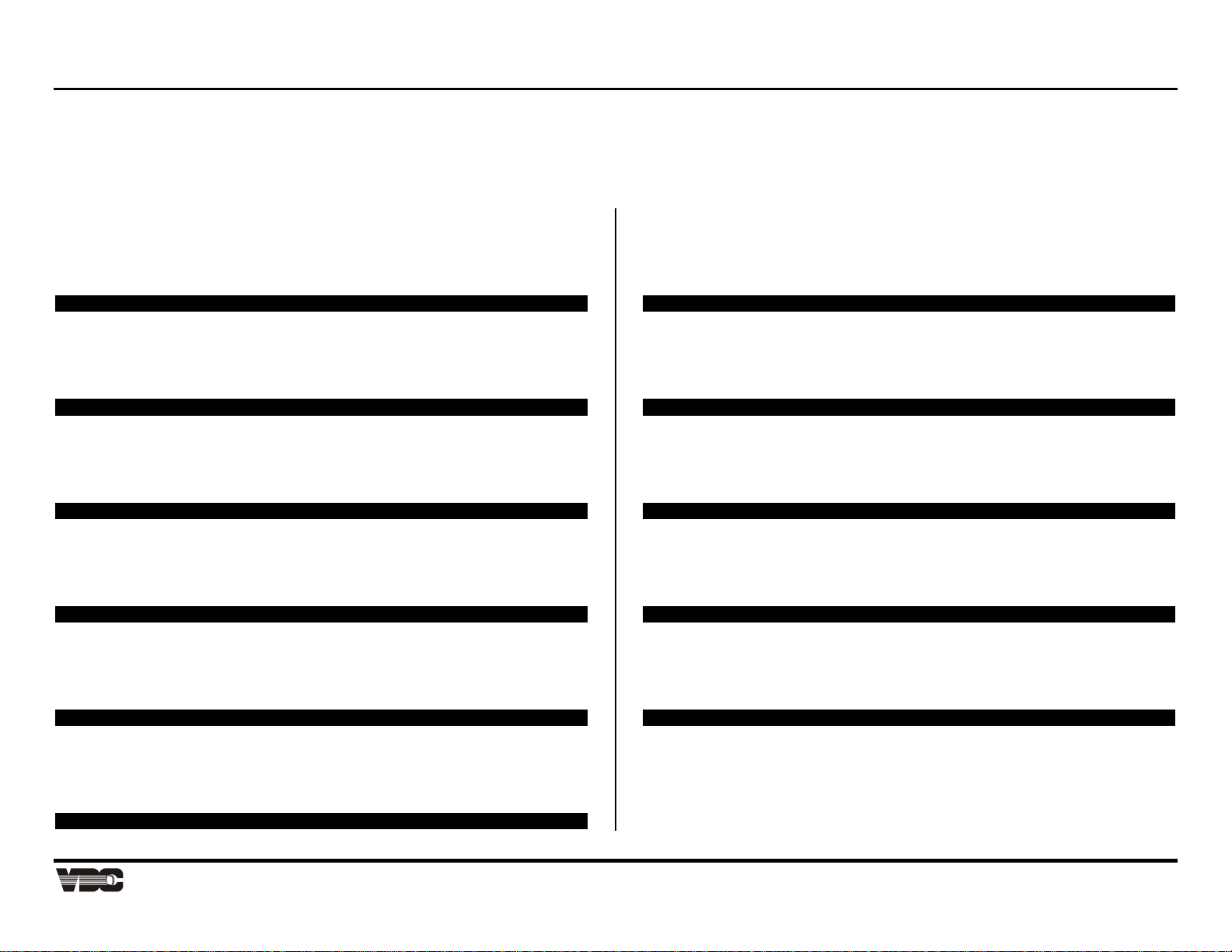
Appendix B
B.7.1 Sample Data Transmissions
Table B-4 shows complete examples of common binary commands for projector control. All are for projector “0”.
Table B-4. RS-232 Commands in v.4.0
Set Power Off 01 07 00 00 03 FF 08 00 00 0E
Set Power On 01 07 00 00 03 FF 08 1B 81 00 0E
Request Power Status 01 06 00 00 03 FF 88 00 0E
Reply with Power Status 01 07 03 FF 00 00 88 1B 81 00 0E (On)
Set Standby Off 01 07 00 00 03 FF 3D 00 00 0E
Set Standby On 01 07 00 00 03 FF 3D 1B 81 00 0E
Request Standby Status 01 06 00 00 03 FF BD 00 0E
Reply with Standby Status 01 07 03 FF 00 00 BD 1B 81 00 0E (On)
Set Pic Mute Off 01 07 00 00 03 FF 1B 8E 00 00 0E
Set Pic Mute On 01 07 00 00 03 FF 1B 8E 1B 81 00 0E
Request Pic Mute Status 01 06 00 00 03 FF 8E 00 0E
Reply with Pic Mute Status 01 07 03 FF 00 00 8E 1B 81 00 0E (On)
Set Audio Mute Off 01 07 00 00 03 FF 0D 00 00 0E
Set Audio Mute On 01 07 00 00 03 FF 0D 1B 81 00 0E
Request Audio Mute Status 01 06 00 00 03 FF 8D 00 0E
Reply with Audio Mute Status 01 07 03 FF 00 00 8D 1B 81 00 0E (On)
Set Contrast to 0 01 07 00 00 03 FF 56 00 00 0E
Set Contrast to 64 01 07 00 00 03 FF 56 40 00 0E
Request Contrast Value 01 06 00 00 03 FF D6 00 0E
Reply with Contrast Value 01 07 03 FF 00 00 D6 40 00 0E (64, 50%)
Set Volume to 0 01 07 00 00 03 FF 34 00 00 0E
Set Volume to 64 01 07 00 00 03 FF 34 40 00 0E
Request Volume Value 01 06 00 00 03 FF B4 00 0E
Reply Volume Value 01 07 03 FF 00 00 B4 40 00 0E
Set Brightness to 0 01 07 00 00 03 FF 55 00 00 0E
Set Brightness to 128 01 07 00 00 03 FF 55 80 00 0E
Request Brightness Value 01 06 00 00 03 FF D5 00 0E
Reply with Brightness Value 01 07 03 FF 00 00 D5 80 00 0E (128, 50%)
Set Color to 0 01 07 00 00 03 FF 57 00 00 0E
Set Color to 32 01 07 00 00 03 FF 57 20 00 0E
Request Color Value 01 06 00 00 03 FF D7 00 0E
Reply with Color Value 01 07 03 FF 00 00 D7 20 00 0E (32, 50%)
Set Tint to 0 01 07 00 00 03 FF 58 00 00 0E
Set Tint to 32 01 07 00 00 03 FF 58 20 00 0E
Request Tint Value 01 06 00 00 03 FF D8 00 0E
Reply with Tint Value 01 07 03 FF 00 00 D8 20 00 0E (32, 50%)
Set Detail to 0 01 07 00 00 03 FF 59 00 00 0E
Set Detail to 32 01 07 00 00 03 FF 59 20 00 0E
Request Detail Value 01 06 00 00 03 FF D9 00 0E
Reply with Detail Value 01 07 03 FF 00 00 D9 20 00 0E (32, 50%)
Select Channel 1 01 07 00 00 03 FF 0B 1B 81 00 0E
Select Channel 3 01 07 00 00 03 FF 0B 03 00 0E
Request Current Channel 01 06 00 00 03 FF 8B 00 0E
Reply with Channel 01 07 03 FF 00 00 8B 03 00 0E (channel 3)
Select Input (0,1) 01 08 00 00 03 FF 09 00 1B 81 00 0E
Select Input (1,5) 01 08 00 00 03 FF 09 1B 81 05 00 0E
Request Current Input 01 06 00 00 03 FF 89 00 0E
Reply with Input 01 08 03 FF 00 00 89 1B 81 05 00 0E
(switcher 1, slot 5)
Display Systems
B-11
Artisan Technology Group - Quality Instrumentation ... Guaranteed | (888) 88-SOURCE | www.artisantg.com
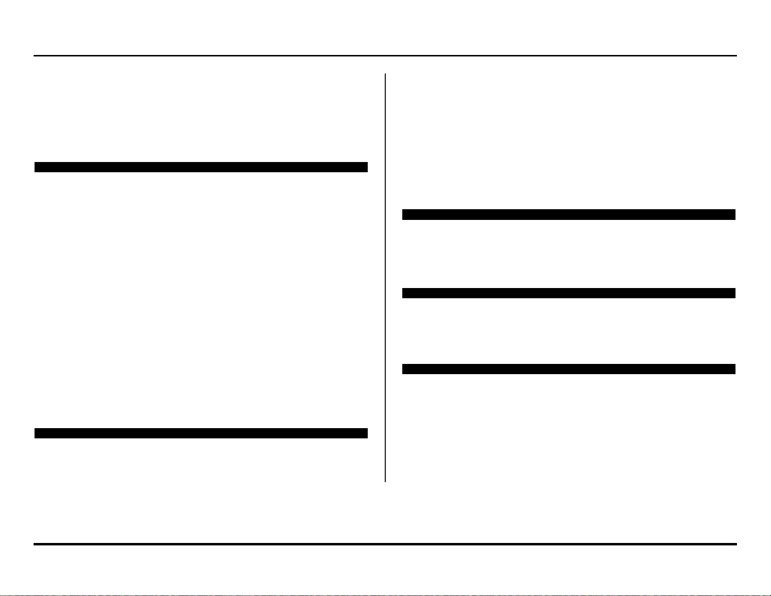
Marquee 8521 Ultra Green (HUD) User's Manual
Select Recall (00) 01 07 00 00 03 FF 0C 00 00 0E
Select Recall (15) 01 07 00 00 03 FF 0C 0F 00 0E
Request Current Recall 01 06 00 00 03 FF 8C 00 0E
Reply with Recall 01 07 03 FF 00 00 8C 0F 00 0E
(recall 15)
Reply with Recall 01 07 03 FF 00 00 8C 00 00 0E
(recall 0, i.e. using input memory)
Request Signal Status, Freq 01 07 00 00 03 FF 91 00 00 0E
Reply w/ Sig.Status,Freq 01 0B 03 FF 00 00 91 00 0C 4E 17 70 00 0E
(31.5Khz,60.0Hz)
Request Sig. Status, State 01 07 00 00 03 FF 91 1B 81 00 0E
Reply w/ Sig. Status, State 01 08 03 FF 00 00 91 1B 81 00 00 0E
(Good,SignalLocked)
Reply with Signal Status, State 01 08 03 FF 00 00 91 1B 81 1B 81 00 0E
(Changing src)
Reply with Signal Status, State 01 08 03 FF 00 00 91 1B 81 02 00 0E
(Error,sync err)
Request Signal Status, Sync On? 01 07 00 00 03 FF 91 02 00 0E
Reply with Signal Status, Sync 01 08 03 FF 00 00 91 02 00 00 0E
(No sync)
Reply with Signal Status, Sync 01 08 03 FF 00 00 91 02 1B 81 00 0E
(Sync On Green)
Reply with Signal Status, Sync 01 08 03 FF 00 00 91 02 02 00 0E
(Composite Sync)
Reply with Signal Status, Sync 01 08 03 FF 00 00 91 02 03 00 0E
(Sep.HSync on H.)
Reply with Signal Status, Sync 01 08 03 FF 00 00 91 02 06 00 0E
(SyncfromDecoder)
Request Ping 01 06 00 00 03 FF 81 00 0E
Reply w/ Data 01 0D 03 FF 00 00 81 02 03 04 61 00 48 00
00 0E
See page 18 for additional information
Select Internal Test Pattern 01 08 00 00 03 FF 7F 07 17 00 0E
(crosshatch)
Select Internal Test Pattern (ext.) 01 08 00 00 03 FF 7F 07 00 00 0E
Request Current Test Pattern 01 07 00 00 03 FF FF 07 00 0E
Reply with Current Test Pattern 01 08 03 FF 00 00 FF 07 1B 93 00 0E
(dots in crosshatch)
Reply with Current Test Pattern 01 08 03 FF 00 00 FF 07 00 00 0E
(ext.)
Select Internal Frequency (1) 01 07 00 00 03 FF 35 1B 81 00 0E
Select External Freq (signal) 01 07 00 00 03 FF 35 00 00 0E
Request Current Internal Freq 01 06 00 00 03 FF B5 00 0E
Reply with Internal Freq
01 07 03 FF 00 00 B5 1B 81 00 0E
(Int Freq 1, menu)
Set Proj Address to 0 01 08 00 00 03 FF 02 00 00 00 0E
Set Proj Address to 14 01 08 00 00 03 FF 02 00 1B 8E 00 0E
Request Proj Address (broadcast) 01 06 80 00 03 FF 82 00 0E
Reply with Proj Address 01 08 03 FF 80 00 82 00 1B 8E 00 0E
(proj address 14)
If broadcasting: Same as above examples, except use “80 00” for destination
Example:
Set Tint to 0 01 07 80 00 03 FF 58 00 00 0E
Set Tint to 32 01 07 80 00 03 FF 58 20 00 0E
Request Tint Value (max. 1 proj.)* 01 06 80 00 03 FF D8 00 0E
Reply w/ Tint Value (max. 1 proj.)* 01 07 03 FF 80 00 D8 20 00 0E (32, 50%)
* Do not broadcast a request to more than one projector, as it may generate multiple
attempts at replies that could collide on the network.
B-12 Marquee Projectors RS-232 Control
Artisan Technology Group - Quality Instrumentation ... Guaranteed | (888) 88-SOURCE | www.artisantg.com

Appendix B
This section includes additional notes about some of the more complex RS-232 messages.
B.7.2 “Standby” Command
During standby entered via normal keypad-projector operation, the picture is blanked, the audio is
muted and you can perform no operation from the keypad except to “get out of standby”. This type of
standby occurs when you use the Standby key on either the keypad or Marquee switcher (available
only from Presentation level), when you use the Picture Mute key on the Extron switcher, or when
you send RS-232 standby keycodes from a controller.
The RS-232 “set standby” command triggers a significantly different type of standby. This standby
command blanks the picture and mutes the audio as usual, but you can still execute most other
projector commands as well — you are not locked out. In addition, note that it is not necessary to be
in presentation mode in order to enter standby via the RS-232 command.
WHILE IN STANDBY…
• the picture and audio are both off.
• you can issue other projector commands as desired.
• a request of Contrast, Brightness or Audio Mute reports the value that will be
• restored after coming out of standby.
• any Picture Mute command is ignored.
• switcher slot buttons do not function.
• commands causing an unblanked picture take effect only after leaving standby
• mode (exit via a keypress or RS-232 methods).
• the amber LED status light is lit on the projector and connected switcher.
LEAVING STANDBY…
Exit standby via a keypress or RS-232 method. The amber LED status light will
B.7.3 “Picture Mute” Command
The RS-232 “set pic mute” command blanks only the picture — the audio is not affected. Otherwise,
this command is similar to the RS-232 “set standby” command. You can use most other projector
commands while in “pic mute” mode. Note that it is not necessary to be in presentation mode in
order to enter Picture Mute via the RS-232 command. Note also that a Picture Mute command is
ignored if you are already in any form of standby.
WHILE IN PICTURE MUTE…
• the picture is off but the audio is on
• you can issue other projector commands as desired.
• commands causing an unblanked picture take effect only after leaving picture
• mute mode (exit via a keypress or RS-232 methods).
• a request of Contrast or Brightness reports the value that will be restored after
• coming out of Picture Mute.
• the amber LED status light is lit on the projector and connected switcher.
LEAVING PICTURE MUTE …
Exit Picture Mute via a keypress or RS-232 method.
Note: You have no way of knowing that a projector has only the picture muted rather than being
in standby except if you hear audio from the current source. If you mistake Picture Mute for
Standby and try to leave by pressing the standby key, you will enter standby rather than
leave it. Press the standby key once again to leave standby and restore the picture.
go out.
Display Systems
Artisan Technology Group - Quality Instrumentation ... Guaranteed | (888) 88-SOURCE | www.artisantg.com
B-13

Marquee 8521 Ultra Green (HUD) User's Manual
E
E
B.7.4 “Projector Address” Command
Make sure that if you change a projector’s address, either change the address in all future messages
as well or issue a command that is broadcast (set broadcast bit to “1”).
B.7.5 “Signal Status” Command
The signal status command enables you to request and obtain specific information about the current
signal, namely its frequency, state or type of sync. Note that one (only) of these descriptors must
be included as P1 in every signal status request message. Resulting signal status replies will then
include one or two additional parameters as necessary to fully describe the status of P1. Frequency,
state and sync signal status messages are further described below.
Note: There is no “set” command for signal status information — you can issue requests and receive replies
only.
P1 = FREQUENCY ($00)
If you want to determine the horizontal and vertical frequencies of the current signal, you can send a
“request signal status/frequency” to the projector. Note that this message must include both the
signal status code ($91) as well as the P1 frequency code ($00) as shown in the example from Table
B-4.
FREQUENCY REPLIES:
A reply to the “request signal status/frequency” message supplies the horizontal and vertical
frequencies of the current signal. In the example from Table B-4, P2 is the horizontal frequency and
P3 is the vertical frequency as shown in the following illustration. Convert to decimal format and
assume two decimal places.
P1 = STATE ($01)
If you want to determine the state of the current signal, you can send a “request signal status/state”
to the projector. Note that this message must include both the signal status code ($91) as well as the
P1 state code ($01) as shown in the example from Table B-4. Note also the “escaped” $01 byte.
STATE REPLIES:
A reply to the “request signal status/state” message includes another parameter (P2) whose value
describes the state of the current signal as a good locked signal ($00), a changing signal ($01), or an
error characterized by an unstable or missing signal ($02). See Table B-4 for an example of each.
Note: Errors are not detected or reported for NTSC and PAL frequencies or certain computer-
generated sources having these frequencies. See Table B-4.
P1 = SYNC ON? ($02)
If you want to determine the sync of the current signal, you can send a “request signal status/sync”
to the projector. Note that this message must include both the signal status code ($91) as well as the
P1 sync code ($02) as shown in the example from Table B-4.
01 07 00 00 03 FF 00 0
01 07 00 00 03 FF 00 0E
91 00
91 00 81
01 07 00 00 03 FF 00 0
B-14 Marquee Projectors RS-232 Control
Artisan Technology Group - Quality Instrumentation ... Guaranteed | (888) 88-SOURCE | www.artisantg.com
91 02

Appendix B
01 06 00 00 03
00 0E
81
n
SYNC REPLIES:
A reply to the “request signal
status/sync” message includes a
second parameter (P2) to describe
the sync. Possible values are
defined in Table B-5.
B.7.6 “Ping” Command
Use ping to request and obtain basic projector information, such as projector type and current
software version. Like most RS-232 requests, a ping request contains no data (parameters):
Note: There is no “set” command for ping — you can issue requests and receive replies only.
PING REPLIES
The Ping reply contains data for the six parameters necessary to fully answer the ping request,
as shown in the example from Table B-4:
P4 = Maintenance Version
P2 = Major Version
Table B-5. Sync Replies
0 None, no sync present
1 Sync-on-green
2 Composite sync
3 Separate H sync on H
6 Sync from decoder
7 Sync on internal
FF
P6 = Type Versio
01 0D 03 FF 00 00 81 00 0E02 03 04 61 00 48 00
P1 = Model
(Marquee, 68k)
P3 = Minor Version
Figure B-5. Ping Reply Contents
This reply represents V3.4.a.072 Beta of the main (68K) software.
B.7.7 “Test Pattern” Diagnostic Command
The “Diagnostic:Test Pattern” command enables you to select, request or obtain the number of
a specific test pattern. Note that such commands must include both the “diagnostic” command
code as well as the “test pattern” parameter (P1). This parameter represents the diagnostic to
be run and ensures that the proper diagnostic is run (in this case “test pattern”). Shown below
is the “request” example from Table B-4.
01 07 00 00 03 FF 00 0E
DIAGNOSTIC/TEST PATTERN REPLIES
Resulting replies will then include an additional parameter (P2) representing the number
(name) of the test pattern. The example below shows that a “dots in crosshatch” pattern is
present.
01 08 03 FF 00 00 00 0E
EXITING FROM A TEST PATTERN
P5 = Beta Version
FF 07
FF 07 1B 93
Exit a test pattern by pressing the Exit key or by selecting test pattern “0”.
Display Systems
Artisan Technology Group - Quality Instrumentation ... Guaranteed | (888) 88-SOURCE | www.artisantg.com
B-15

Marquee 8521 Ultra Green (HUD) User's Manual
B.7.8 Color Modulation (CNM) Command
Use this message to set or get the current contrast modulation values. There are 3 colors in each of 8 on-screen zones.
Table B-6. Color Modulation (CNM) Command
Message = Adjust Zonal Contrast
Parameter Name Description
P1 Which adjustment P1 is made of three characters. The first specifies zone or command, and the second red, green or blue.
(2 bytes)
byte 1: 0 = Left,
1 = Right,
2 = Top,
3 = Bottom,
4 = Top Left,
5 = Top Right,
6 = Bottom Left,
7 = Bottom Right,
8 = Save to Eeprom
9 = Restore from
EEprom
byte 2: 0 = red,
1 = green,
2 = blue
Example:
0,2 specifies an adjustment of blue left zone.
P2
(1 byte)
Message = Read Zonal Contrast
P1 Which adjustment Specifies which color and zone of zonal contrast adjustment to return.
Reply to Read Zonal Contrast Message
P1
(2 bytes)
P2
(1 byte)
value 0 - 255 (8 bits)
Which adjustment Specifies which color and zone of zonal contrast adjustment to return.
value The value of the specified adjustment
Example – Contrast modulation message
01 09 00 00 03 ff 2e 1b 81 00 41 00 0e = set right red zone to 65.
Saving and Discarding Contrast Modulation Values
Writing to hardware will change values & save values in shadow EEPROM memory structure but will not save permanently to EEPROM for next
power up. You must use the Save command to do this. When you use byte 1 of P1 for the save or restore operation, the rest of the message is
unused.
Color Temperature (SCT) Command
Use this message to set or get the current color temperature, selecting from a list of color temperatures. Note that white balance must be selected in
order to provide a color temperature between 3200°K and 9300°K.
B-16 Marquee Projectors RS-232 Control
Artisan Technology Group - Quality Instrumentation ... Guaranteed | (888) 88-SOURCE | www.artisantg.com

Appendix B
B.7.9 Color Temperature Modify Command (CTM)
Use this message to set (alter) or get the red, green and blue levels present for a defined color temperature. This command does not select a color
temperature.
Table B-7. Color Temperature Command (CTM)
• Value Range: 0 = 3200K, 2 = 6500K, 3 = 9300K, 5 = source custom, 6 = white balance
Message = Adjust Color Temperature
Parameter Name Description
P1
(3 bytes)
Which adjustment
byte 1: 0 = G2,
1 = drive,
2 = white balance
8 = Save to Eeprom
9 = Restore from
EEprom
byte 2: 0 = red,
1 = green,
2 = blue
byte 3: 0 = 3200K,
1 = 5400K(Future),
2 = 6500K,
3 = 9300K,
5 = source custom
P1 is made of three characters. The first specifies G2, drive or white balance, the second red, green or blue, and the third
what to set.
Example:
0,2,3 specifies an adjustment of blue G2 for the 9300K temperature setting.
2 specifies an adjustment to the white balance setting Bytes 2 & 3 are not relevant (but must be used anyway) when
adjusting white balance
P2
(2 bytes)
Message = Read Color Temperature
P1 Which adjustment Specifies which color temperature adjustment to return.
Reply to Read Color Temperature Message
P1 Which adjustment Specifies which color temperature adjustment to return.
P2 value The value of the specified adjustment
value 0-4095, G2 (12 bits) (MSB,LSB) (most significant digit, least significant digit)
0 - 255, drive (8 bits) (0,LSB)
0 - 255, white balance (8 bits) (0,LSB)
Example - Color Temperature Modify:
010b 00 00 03 ff 52 00 00 02 08 00 00 0e = set 6500K red G2 to 2048.
Saving and Discarding Modified Color Temperature Values
Writing to hardware will change values & save values in shadow EEPROM memory structure but will not save permanently to EEPROM for next
power up. You must use the Save command to do this — this save applies only to the currently selected temperature, not all temperatures When
byte 1 of P1 is used for the save or restore operation, the rest of the message is unused.
If the requested data is unrecognized, no message is returned. If the requested adjustment is invalid (out of range), no adjustment is made.
If you query a parameter for a color temperature other than what is currently selected, a switch to the queried temperature may occur.
Display Systems
B-17
Artisan Technology Group - Quality Instrumentation ... Guaranteed | (888) 88-SOURCE | www.artisantg.com

Marquee 8521 Ultra Green (HUD) User's Manual
This page intentionally left blank
B-18 Marquee Projectors RS-232 Control
Artisan Technology Group - Quality Instrumentation ... Guaranteed | (888) 88-SOURCE | www.artisantg.com

Appendix C Glossary
This appendix defines many of the terms used in this manual as they apply to the Marquee projection system.
ACON (Automatic Convergence)
ACON is an optional automatic convergence
feature available for Marquee series projectors.
With ACON installed, convergence of the red,
green and blue images is performed accurately
and automatically with minimal user intervention.
ASI (Automatic Source Interpolation)
A process whereby a display setup for a given
source is approximated from other setups already
in memory. For more information about ASI, refer
to the ASR entry in section 3.7, Utility Features.
ASR (Automatic Source Recall)
A process whereby a display setup for a given
source is chosen from memory according to its
signal parameters (horizontal and vertical
frequencies). For more information about ASR,
refer to the ASR entry in section 3.7, Utility
Features.
Active Line Time
The time, inside one horizontal scan line, during
which video is generated.
Ambient Light Rejection
The ability of a screen to reflect ambient light in a
direction away from the "line of best viewing".
Curved screens usually have good ambient light
rejection. Flat screens usually have less ambient
light rejection.
Analog Video
The video output of most computers and video
tape machines. Analog video can generate a
large number of colors.
Blanking Time
The time inside one scan line during which video
is not generated. The blanking time of the input
signal must be equal to or greater than the
retrace time of the projector.
Bow
A horizontal curve in the center of the image,
and/or a vertical curve across an image.
Brightness
Brightness in projection usually describes the
amount of light emitted from a surface such as a
screen. Brightness is measured in lumens, footlamberts, foot-candles, or lux.
Candela or Candle
The intensity of light is measured in candelas.
Channel
A 2-digit number with user-assigned source input
information. This information includes a physical
input (switcher, slot), a setup memory (input or
recall), and a name or description. Assignments
are made through the Channel List.
Channel List
A list of up to 99 channels (explained above)
which may be created, edited, or deleted by the
user. The Channel List feature provides an
alternative, and sometimes easier, way to select
sources and their setups.
Color Shift
The change in the tint of a white field across an
image.
Aspect Ratio
The ratio of the width of an image to its height.
Automatic Convergence
The automatic alignment of the projected red,
green and blue images on the projection screen.
Autolock
The ability of the projector to automatically
synchronize to the horizontal and vertical scan
frequencies of an input signal.
Bandwidth
The frequency range of the projector's video amplifier.
Display Systems
Artisan Technology Group - Quality Instrumentation ... Guaranteed | (888) 88-SOURCE | www.artisantg.com
C-1
Color Temperature
This term refers to the coloration (reddish, white,
bluish, etc.) of a white image. (It does not refer to
the brightness of a white image.) The Kelvin (K)
temperature scale is used to measure color
temperature.
Color Temperature Uniformity
The accuracy of color temperature at any
location.
Composite Video
This term refers to the output of video tape
players and some computers. Synchronization,
luminance, and color signals are combined on
one output cable.

Marquee 8521 Ultra Green (HUD) User's Manual
Contrast (ratio)
Gain or Screen Gain
The ratio of brightness of the brightest possible
area to the darkest possible area of an image.
Convergence
The alignment of the projected red, green and
blue images on the projection screen.
Current Setup Memory
The setup memory which is currently being used
to display a given source's image.
Curved Screen
A projection screen which is curved to improve
screen gain. Curved screens usually have screen
gains which are greater than 1 but viewing angles
much less than 180E.
Decoder
A device that converts NTSC, PAL, PAL M, PAL
N, PAL 60, SECAM or NTSC 4.43 video to RGB
video (Marquee Multi-standard Decoder).
Diffused Screen
A type of rear-projection screen which spreads
the light striking it. Screen gain is less than 1 but
audience viewing angles are increased.
Display Setting
The level of a display adjustment. Some display
adjustments are: Contrast, Brightness, Blanking,
Bow, Size, Keystone, Pincushion, Focus and
Convergence.
Flicker
A rapid variation in brightness created when the
frame rate is too slow. (See also Interlace.)
Frame Rate
The frequency at which complete images are
generated. For non-interlaced signals, the frame
rate is identical to the vertical frequency. For
interlaced signals, the frame rate is one half of
vertical frequency.
Foot-candle
The intensity of visible light per square foot.
1 foot-candle = 1 lumen/square foot = 10.76 lux
Foot-lambert
The luminance (brightness) which results from
one foot-candle of illumination falling on a
perfectly diffuse surface.
The ability of a screen to direct incident light to an
audience. A flat matte white wall has a gain of
approximately 1. Screens with gain less than 1
attenuate incident light; screens with gain more
than 1 direct more incident light to the audience
but have a narrow viewing angle. For example:
An image reflecting off a 10 gain screen appears
10 times brighter than it would if reflected off a
matte white wall. Curved screens usually have
larger gain than flat screens.
Gamma Correction
A feature provided on Marquee Ultra Series,
9500DM and 8500SM models which boosts the
blue color output when required to provide
improved picture intensity and color uniformity.
Geometry
The reproduction of a straight and rectangular
image.
Help Page
A display of help information on the projection
screen.
Horizontal Frequency
Also called horizontal scan rate or line rate, this is
the frequency at which scan lines are generated.
Horizontal frequencies vary amongst sources.
Hot Spot
A circular area of a screen where the image
appears brighter than elsewhere on the screen.
The hot spot always appears located along the
line of sight and "moves" with the line of sight.
High gain screens and rear screens designed for
slide or movie projection usually have a hot spot.
Input
A physical connection route for a source signal
defined by two numbers; a switcher number and a
slot number. If the switcher number is 0, the input
is a projector input.
Image Shifter Module
An optional interface module which can lengthen
CRT life while maintaining a bright picture by
slowly shifting the image about the CRT
faceplate. Image shifting occurs both horizontally
and vertically. Shift range is totally controllable by
the user. NOTE: Standard on the 9500LC.
Input Memory
A setup memory which is associated with a
particular projector or switcher input.
C-2 Glossary
Artisan Technology Group - Quality Instrumentation ... Guaranteed | (888) 88-SOURCE | www.artisantg.com

Appendix C
Interface
Loopthrough (Loopthru)
A device that accepts an input signal for display
by the projector.
Interlace
A method used by video tape players and some
computers to double the vertical resolution
without increasing the horizontal line rate. If the
resulting frame rate is too low, the image may
flicker depending on the image content.
Keypad
A device which allows the user to control
projector settings and operation. There are four
different keypad types which may be used with
the projector: built-in, IR remote, wired remote,
and presenter's. For more information about
these keypads, refer to the keypads entry in
section 3.2, Projector Basics.
Keystone
A distortion of the image which occurs when the
top and bottom borders of the image are not
equal in length. Side borders slant in or out,
producing a keystone shaped image.
Learn Screen
An ACON function which stores screen position
data in memory for future reference. Learn
Screen is usually performed only once per
projector installation. If the ACON Locator
Assembly or screen is moved (i.e., the projector
installation changes to ceiling mount), the Learn
Screen function must be repeated.
Linearity
The reproduction of the horizontal and vertical
size of characters and/or shapes over the entire
screen.
Line of Best Viewing
When light from a projector is incident on a
screen, the light reflects from the screen such that
the angle of reflection equals the angle of
incidence. The Line of Best Viewing is along the
line of reflection.
Locator Assembly
The Locator Assembly, situated on the front of
projectors which include the ACON automatic
convergence feature, is the "eye" of the ACON
system. It includes a photosensor/lens
component which mechanically scans the
projected display at each convergence point while
sensing relative positions of each projected color.
The method of feeding a series of high
impedance inputs from a single video source with
a coaxial transmission line in such a manner that
the line is terminated with its characteristic
impedance at the last input on the line.
Lumen
The amount of visible light emitted by a light
source is measured in lumens.
Lux
The amount of visible light per square meter
incident on a surface.
1 lux = 1 lumen/square meter = 0.093 footcandles
Menu
A list of options which are displayed on the
screen for selection by the user.
NTSC Video
A video output format of some video tape and
disk players. There are two types of NTSC
(National Television Standards Committee) video:
NTSC 3.58 and NTSC 4.43. NTSC 3.58 is used
primarily in North America and Japan. NTSC
4.43 is less commonly used.
Optical Screen
A type of rear-projection screen which re-directs
light through the screen to increase image
brightness in front of the screen. Screen gain is
usually greater than 1 but audience viewing
angles are reduced.
PAL Video
A video output format of some video tape and
disk players (used primarily in Europe, China and
some South American and African countries). All
PAL (Phase Alternating Line) video is a 50 Hz
standard with 768 x 576 resolutions.
Pincushion
A distortion of the image which occurs when the
borders are concave or convex.
Pixel (Picture Element)
The smallest discernable element of a computer
generated image.
Display Systems
Artisan Technology Group - Quality Instrumentation ... Guaranteed | (888) 88-SOURCE | www.artisantg.com
C-3

Marquee 8521 Ultra Green (HUD) User's Manual
Presentation Level
RGB Video
The projector is at presentation level when an
image is (or may be) displayed and no control,
dialog, error, or help messages are displayed.
For example, if a help page is displayed, the
projector is not at presentation level.
Projector-to-Screen Distance
Also called "Throw Distance", the distance
between the front of the projector's green lens
and the screen.
Protocol
The type of code format utilized by IR keypad(s).
The standard code is Protocol A. By using two
different protocols, two projectors may be used
side by side while being controlled independently
by their remote IR keypads.
Rear Screen
A translucent panel for screen projection.
Incident light travels through the incident surface
of a rear screen and forms an image on the other
surface.
Recall Memory
A setup memory which is not associated with any
particular input.
Resolution - CRT
The maximum number of lines that can be
distinguished on the face of a CRT.
Resolution -Lens
The maximum number of alternate white and
black horizontal lines that can be distinguished on
a screen when a photographic target is placed
between the lens and a light source, and
illuminated by that light source.
Resolution - Projector
The smaller of CRT and Lens resolutions.
The video output of most computers. It can be
analog or digital. Analog RGB video has 3, 4, or
5 wires; one for red, one for green, one for blue,
and none, one or two for sync. For three wire
RGB, the green wire usually provides sync. (See
also TTL Video).
Scan Frequency
The horizontal or vertical frequency at which
images are generated.
Scan Line
One scan line is one horizontal line on the
display.
SECAM
A video output format of some video tape and
disk players (used primarily in France). SECAM
(Sequential Couleur á Mémoire) signals are
similar in resolution and frequency to PAL signals.
The primary difference between the two
standards is in the way color information is
encoded.
Setup Memory
A projector memory which stores user-adjustable
display settings. There are two types of setup
memories: Input and Recall. Both memory types
store the same parameters. The only difference
is that Input memories store display settings for a
particular physical input (i.e., switcher 0, slot 1)
and Recall memories can be used with any input.
Slidebar
A slidebar is a graphical display of an adjustment
setting. The setting is displayed on a percentage
scale.
Source
A device, such as a computer or VCR, which may
be connected to the projector for display.
Retrace Time (Horizontal)
The minimum time required for the projector to
move the position of the scanning spot from the
Spot Size
The diameter of the smallest dot that can be
generated on the face of a CRT.
right edge to the left edge of a CRT.
Rise Time
The time required by the video amplifier of the
projector to increase its output from 10% to 90%
of the maximum value.
C-4 Glossary
Artisan Technology Group - Quality Instrumentation ... Guaranteed | (888) 88-SOURCE | www.artisantg.com

Appendix C
Sync
This term refers to the part of the video signal that
is used to stabilize the picture. Sync can take
three forms:
1)"Composite sync" when the horizontal and
vertical components are together on one cable.
2)"Sync on green" when the sync is part of the
green video.
Maximum brightness is seen when you are
positioned within the viewing cone. The
horizontal and vertical viewing angles are the
horizontal and vertical angles of the cone.
White Balance
White Balance refers to the color temperature of
white used by the projector.
White Field
3)"Separate sync" or "H.SYNC and V.SYNC"
when the horizontal and vertical components of
the sync are on two separate cables.
Sync Width
The duration of each sync pulse generated by a
computer. The sync width is part of the blanking
time.
TTL Video
A type of RGB video with digital characteristics.
Terminated
A wire connecting a single video source to a
display device, such as a projector, must be
terminated by a resistance (usually 75Ω for
video).
Throw Distance
Also called "Projector-to-Screen Distance", the
distance between the front of the projector's
green lens and the screen.
Variable Scan
The ability of a projector to synchronize to inputs
with frequencies within a specified range.
A white field is the area of an image that is white
only. For example, a full white field is an image
that is white everywhere. A 10% white field is a
white area (usually rectangular) that occupies
10% of the image; the remaining 90% is black.
Vertical Frequency
The frequency at which images are generated.
Vertical frequencies vary amongst sources. This
term is also called vertical scan rate.
Video
The signal that is used by display devices (such
as projectors) to generate a picture. This term
also refers to the output of video tape/disk players
and computers.
Video Decoder
A device that converts NTSC, PAL, SECAM or
NTSC 4.43 video to RGB video (Marquee Multistandard Decoder).
Viewing Angle
Screens do not reflect equally in all directions.
Most light is reflected in a conical volume which is
centered around the "line of best viewing".
Display Systems
C-5
Artisan Technology Group - Quality Instrumentation ... Guaranteed | (888) 88-SOURCE | www.artisantg.com

Marquee 8521 Ultra Green (HUD) User's Manual
This Page Intentionally Left Blank
C-6 Glossary
Artisan Technology Group - Quality Instrumentation ... Guaranteed | (888) 88-SOURCE | www.artisantg.com

Artisan Technology Group is your source for quality
new and certied-used/pre-owned equipment
• FAST SHIPPING AND
DELIVERY
• TENS OF THOUSANDS OF
IN-STOCK ITEMS
• EQUIPMENT DEMOS
• HUNDREDS OF
MANUFACTURERS
SUPPORTED
• LEASING/MONTHLY
RENTALS
• ITAR CERTIFIED
SECURE ASSET SOLUTIONS
SERVICE CENTER REPAIRS
Experienced engineers and technicians on staff
at our full-service, in-house repair center
Instra
Remotely inspect equipment before purchasing with
our interactive website at www.instraview.com
Contact us: (888) 88-SOURCE | sales@artisantg.com | www.artisantg.com
SM
REMOTE INSPECTION
View
WE BUY USED EQUIPMENT
Sell your excess, underutilized, and idle used equipment
We also offer credit for buy-backs and trade-ins
www.artisantg.com/WeBuyEquipment
LOOKING FOR MORE INFORMATION?
Visit us on the web at www.artisantg.com for more
information on price quotations, drivers, technical
specications, manuals, and documentation
 Loading...