

Page 1
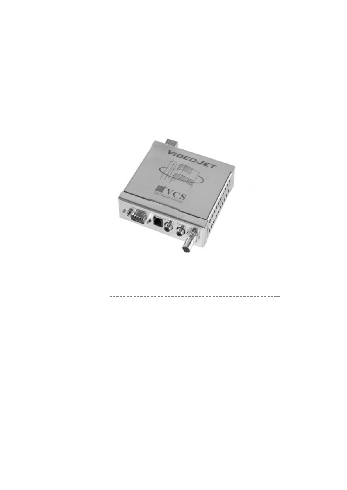
X.21
G.703
VideoJetVideoJet
Manual
Page 2

Copyright This manual is copyrighted by VCS with all rights reserved. Under
the copyright laws, this manual cannot be reproduced in any form
without the prior written permission of VCS. No patent liability is
assumed, however, with respect to the use of the information contained herein.
Edition: February 2000
© Copyright 2000 VCS Video Communication Systems GmbH
Disclaimer This manual has been validated and reviewed for accuracy. The
included sets of descriptions were accurate at the time of this manual’s production. However, succeeding products and manuals are
subject to change without notification. Therefore, VCS assumes no
liability for damages incurred directly or indirectly from errors, omissions or discrepancies between the equipment and this manual.
Trademarks All names for hardware and software used in this manual are
almost certainly registered trademarks and should be treated
accordingly.
4
VideoJet X.21/G.703 Manual
Page 3

Contents
Chapter 1 Preface .......................................................................................13
Chapter 2 Introduction ................................................................................17
Chapter 3 Quick Installation Guide .............................................................29
Purpose of this Manual ........................................................13
Audience .............................................................................13
Conventions ........................................................................14
Special Message Formats.............................................14
Other Conventions ..............................................................15
X.21/G.703 Transmission Concept .....................................18
Typical Applications ......................................................20
Benefits ...............................................................................21
Package Contents ...............................................................23
Front Panel Connectors ......................................................24
Rear Panel Connectors .......................................................26
Step 1: Connecting a Camera or Monitor ............................30
Step 2: Connecting to the X.21 Transmission Line .............31
Step 2: Connecting to the G.703 Transmission Line ...........32
Step 3: Connecting Power ...................................................33
Chapter 4 Hardware Installation .................................................................35
Connecting Video Sources or Displays ...............................35
Connecting Audio Equipment ..............................................36
Connecting Data Terminals .................................................37
Terminal Port ................................................................37
Transparent Data Port ..................................................38
Connecting External Sensors and Controlling
Peripheral Devices ..............................................................39
Connection to the X.21 Leased Line ...................................40
Assignment of the Port to X.21/V.11 ............................42
VideoJet X.21/G.703 Manual
5
Page 4

Contents
Connection to the G.703 Leased Line .................................43
Assignment of the Port to G.703 ...................................44
Chapter 5 Configuration with the NCTerminal Software .............................45
Installation of the NCTerminal Program ...............................46
Starting the Terminal Program ............................................46
Configuration Options in the Main Window
of NCTerminal ......................................................................48
Establishing a Connection.............................................49
Status Displays of NCTerminal .....................................49
Configuring the VideoJet X.21/G.703-
Devices with NCTerminal ..............................................50
Audio and Video Settings ....................................................51
Audio Settings ................................................................52
Video Settings ................................................................54
Alarm Configuration .............................................................55
Alarm Stamping .............................................................55
Alarm Input Activation....................................................56
Motion Detection............................................................57
Checklist for Activating Motion
Detection .......................................................................58
Output Action.................................................................59
Configuration of the Switching Output..................................60
Camera Configuration .........................................................62
Name/Time Stamping....................................................63
Allocation of Camera Name...........................................63
Video Standards ...........................................................63
Interface Configuration ........................................................64
Common Configuration ........................................................66
Realtime clock ...............................................................67
Allocating a Device Name..............................................67
Device Number (ID) ......................................................67
Version Display ..............................................................67
Chapter 6 Advanced Features ....................................................................69
Automatic Connection Feature ............................................69
Video Motion Detection Feature ..........................................70
Firmware Upload .................................................................71
6
VideoJet X.21/G.703 Manual
Page 5

Contents
Chapter 7 Technical Specification ..............................................................73
Network Protocol and Standards .........................................73
Interfaces at the Videojet .....................................................73
Power Adapter .....................................................................74
Physical Specification ..........................................................74
Environmental Specification ................................................74
Electromagnetic Emmissions and Safety ............................75
Chapter 8 Troubleshooting .........................................................................77
General Service Remarks ...................................................77
Basic Functioning ................................................................78
Power LED ...................................................................78
Terminal Program ......................................................... 79
Troubleshooting Connection Problems ...............................79
Troubleshooting the Video Connection ...............................80
Testing the Audio Connection .............................................81
Chapter 9 Glossary .....................................................................................83
Chapter 10 Index ..........................................................................................85
VideoJet X.21/G.703 Manual
7
Page 6

Contents
8
VideoJet X.21/G.703 Manual
Page 7

Figures
Fig. 2-1 VideoJet X.21/G.703 Concept .................... 18
Fig. 2-2 VideoJet X.21 System Concept and
Interfaces............................................................. 22
Fig. 2-3 VideoJet G.703 System Concept and
Interfaces............................................................. 22
Fig. 2-4 VideoJet X.21/G.703 Front Panel
Connectors.......................................................... 24
Fig. 2-5 VideoJet X.21 Rear Panel Connectors.......... 26
Fig. 2-6 VideoJet G.703 Rear Panel Connectors....... 27
Fig. 3-1 Connecting a Camera or Monitor........................ 30
Fig. 3-2 Connecting to the X.21 transmission line............ 31
Fig. 3-3 Connecting to the G.703 Transmission Line....... 32
Fig. 3-4 Connecting Power to the X.21 Interface.............. 33
Fig. 3-5 Connecting Power to the G.703 Interface........... 33
Fig. 4-1 Pin Assignment................................................... 36
Fig. 4-2 Pin Assignment of the I/O Connector .................. 39
Fig. 4-3 Connection Scheme for the X.21 Leased Line.... 41
Fig. 4-4 Pin Assignment of the X.21 Socket on
VideoJet X.21 ................................................ 42
Fig. 4-5 Connection Scheme for the G.703 Leased Line.. 43
Fig. 4-6 Pin Assignment at the G.703 Socket at
VideoJet G.703 ............................................. 44
Fig. 5-1 Configuration of the COM Port............................ 47
Fig. 5-2 Status Display of NCTerminal ............................. 48
Fig. 5-3 Audio and Video Settings.................................... 51
Fig. 5-4 Setting Local Audio Levels .................................. 53
Fig. 5-5 Configuration of the Alarm Inputs ........................ 55
Fig. 5-6 Configuration of the Output Action...................... 58
Fig. 5-7 Configuration of the Switching Output................. 61
VideoJet X.21/G.703 Manual
9
Page 8

Figures
Fig. 5-8 Camera Configuration .......................................... 62
Fig. 5-9 Interface Configuration........................................ 64
Fig. 5-10 Common Configuration........................................ 66
10
VideoJet X.21/G.703 Manual
Page 9

Tables
Tab. 5-1 Connection Status Display ................................. 49
Tab. 5-2 Status Display for Signal Input and Relay
Output ................................................................. 50
Tab. 5-3 Audio Coding Method ......................................... 52
Tab. 5-4 Activation Display ............................................... 56
VideoJet X.21/G.703 Manual
11
Page 10

Tables
12
VideoJet X.21/G.703 Manual
Page 11

Preface
1
Congratulations on your purchase of the VCS VideoJet X.21/
G.703 multimedia LAN adapter for X.21/G.703 leased lines.
The VideoJet X.21/G.703 multimedia LAN adapters provide
connectivity for video, audio and data sources by transmission over
a X.21/G.703 leased line. The units are available as encoder units
VideoJet
sources as cameras for example, or as decoder units Video-
XE/GE
Jet
itor.
VideoJet X.21/G.703 allows for transport of video, accompa-
nying audio (optional) and data over a standardized and leased
X.21/G.703 transmission line.
Purpose of this Manual
This manual describes the features of the VideoJet X.21/
G.703 unit and provides installation and configuration instruc-
tions. When discussing features, functions, or specifications that
apply to both encoder and decoder models, the manual refers to the
VideoJet X.21/G.703 unit without addition.
XS/GS
, featuring a video input for connection of video
, providing a video output for direct connection of a mon-
Audience
To configure and install the VideoJet X.21/G.703 units, you
should have the following background and experience:
l Basicknowledge of network management concepts and termi-
nology.
l Working knowledge of tools and procedures for installing and
operating sensitive electronic equipment.
VideoJet X.21/G.703 Manual
13
Page 12
Preface
Conventions
Special Message
Formats
This manual uses the following symbols and notation in order to
highlight special messages:
Tips and Notes
This symbol marks hints and tips which will make the usage of your
VideoJet X.21/G.703 as simple and comfortable as possible.
Information required
Wherever this symbol appears certain information is required for
correct configuration and operation. Eventually you need to talk to
users, manufacturers of connected equipment or a system administrator of the X.21/G.703 leased line in order to gather the required
information.
Warning
All instructions which are accompanied by the shown symbol
should be carefully followed in order to avoid potential damage to
your VideoJet X.21/G.703 or connected equipment and
ensure your personal safety.
14
VideoJet X.21/G.703 Manual
Page 13

Preface
Other Conventions
This manual uses the following typographical conventions:
italics Command and directory names.
courier font Screen text, user-typed command-line entries.
„courier font“ User typed string, enter without double quotes.
Initial Caps Menu titles and window and button names.
[Enter] Named keys in text are shown enclosed in
[Ctrl]+C Two or more keys that must be pressed simul-
ALL CAPS DOS file and directory names.
square brackets. The notation [Enter] is used
for the Enter key and the Return key.
taneously are shown in text linked with a plus
(+) sign.
<courier font> Screen output, dependent on keyboard entry.
VideoJet X.21/G.703 Manual
15
Page 14

Preface
16
VideoJet X.21/G.703 Manual
Page 15

Introduction
2
For the first time, VideoJet X.21/G.703 implements live video
transmission on an existing X.21/G.703 leased line. Efficient compression, according to the ITU-T standard H.261, enables video
communication on any X.21/G.703 leased line.
VideoJet X.21 only has to be connected to the DCE terminating
adapter (DCE = data circuit-terminating equipment) of the X.21
port. The transmission speed is automatically adapted to the data
transmission rate of the line and ranges from 64 Kbit/s to 2.048
Mbit/s. The device is ready for operation on delivery. A terminal program is supplied for additional configuring.
VideoJet G.703 only has to be connected to the DCE terminating adapter (DCE = data circuit-terminating equipment) of the
G.703 interface. The transmission speed is automatically adapted
to the data transmission rate of the line (2.048 Mbit/s). The device
is ready for operation on delivery. A terminal program is supplied for
additional configuring.
This chapter will familiarize you with the underlying concept of the
VideoJet X.21/G.703 multimedia gateway. It will provide an
overview of the features and will give examples of typical applications. After an introduction to the front and back panel connectors,
you are in a good position to follow the installation and configuration
details given in the subsequent chapters.
VideoJet X.21/G.703 Manual
17
Page 16
Introduction
X.21/G.703 Transmission Concept
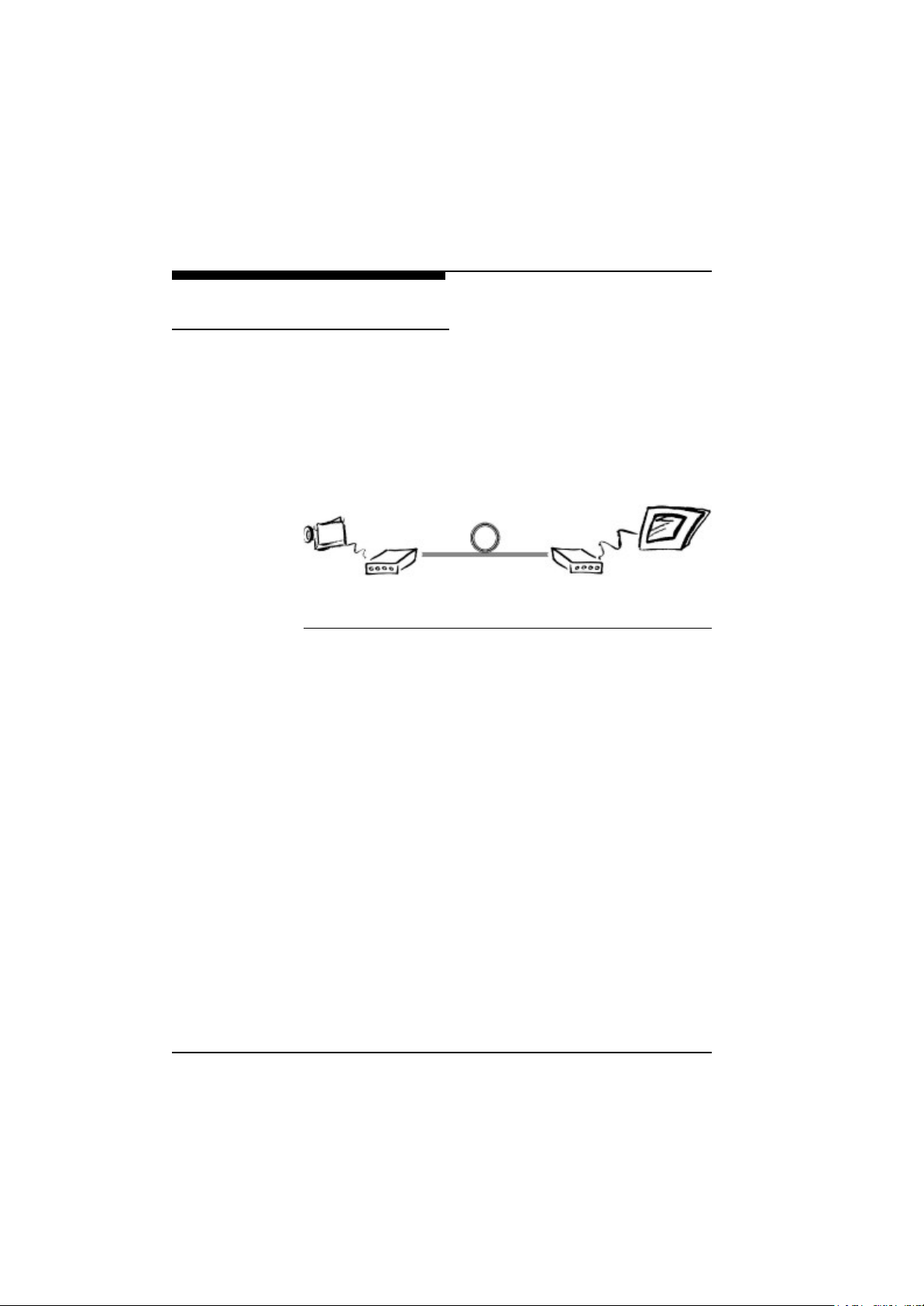
Until now, video and audio signals have been transmitted along
dedicated lines, e.g. coaxial cable. To make use of existing digital
networks and the simpler installation that entails, devices are
required to convert broadband analog video and audio signals for
existing transmission lines. The main advantage clearly lies in the
virtually unlimited loss-free transmission distance between sender
and receiver. The digitized video live image is transmitted across an
X.21/G.703 transmission line with the VideoJet X.21/G.703.
XE
Monitor
Receiver
DTE
XS
DCE
X.21/G.703
Transmission Line
VideoJet
Sender
Transmitter
Fig. 2-1 VideoJet X.21/G.703 Concept
VideoJet
DTE
DCE
The VideoJet X.21/G.703 transmission system was designed,
to enable multimedia data streams over an existing X.21/G.703
leased line. It combines state-of-the art compression technology
with ease-of-use, enabling you to transmit full colour live video with
accompanying full-duplex audio and data over a X.21/G.703 leased
line.
The VideoJet X.21/G.703 functions as a DTE (data terminal
equipment). An adapter used as the line termination for the X.21/
G.703 leased line must therefore be used as the DCE (data circuit
terminating equipment).
The X.21 port of the VideoJet X.21 is directly connected to this
termination. The transmission rate matches the clock output by the
DCE (data circuit-terminating equipment). It can be anything from
64 Kbit/s to 2.048 Mbit/s (x times 64 Kbit/s, where x must not be
greater than 32).
18
VideoJet X.21/G.703 Manual
Page 17

Introduction
The G.703 port of the VideoJet G.703 is directly connected to
this termination. The transmission rate is always 2.048 Mbit/s.
Also X.21/G.703 dial-up networks exist, when the connection is
established by dialling. However, the VideoJet X.21/G.703
operates on the basis of a X.21/G.703 leased line for which the
function for establishing the connection via a dial-up connection is
not supported.
VideoJet X.21/G.703 is available in two versions, as a
VideoJet
XS/GS
sender or as a VideoJet
XE/GE
receiver. The
sender links every PAL or NTSC video source at that side, which is
being monitored to the X.21/G.703 transmission port. The receiver
displays the video image on any standard PAL or NTSC monitor on
the receiving end of the X.21/G.703 leased connection. Remote
control of peripheral components like pan/tilt/zoom cameras is facilitated by the bidirectional serial interface.
With the audio option, bidirectional transmission of audio signals
across the X.21/G.703 leased line is also possible. An additional “A”
in the name indicates that the audio option is included. For example, VideoJet
ignation VideoJet
audio are called VideoJet
XS/GS
senders with the audio option have the des-
XSA/GSA
. VideoJet
XEA/GEA
XE/GE
receivers with
. Two additional cinch sockets
for audio input and output and an RJ11 socket for a telephone
handset are led out of the housing for the audio option only.
Subsequent reconfiguration of a VideoJet
XE/GE
eoJet
receiver is not possible. A complete system always
XS/GS
sender to a Vid-
comprises an encoder (sender) and a decoder (receiver).
Subsequent upgrading to include the audio option is not possible
either.
VideoJet X.21/G.703 Manual
19
Page 18

Introduction
Typical
Applications
VideoJet X.21/G.703 provides a set of advanced features for
remote video surveillance and security: The integrated motion
video sensor will set up a connection autonomously when motion in
the scene is detected. Pre-alarm history is stored in a video ring
buffer for alarm verification:
l Video surveillance of rooms and buildings
l Remote maintenance of machinery
l Facility management and facility security
20
VideoJet X.21/G.703 Manual
Page 19

Introduction
Benefits
VideoJet X.21/G.703 is a flexible, high-performance, easy-touse device that provides a cost-effective solution for transmission
of live video and audio across X.21/G.703 leased lines. With a minimum of setup, you can install and use VideoJet X.21/G.703
within minutes to realize a great variety of applications. The versatility and performance of VideoJet X.21/G.703 is highlighted
by the following list of features:
l Live video, audio, and data transmission over X.21/G.703
leased line
l Supports all usual X.21/G.703 leased lines
l Automatic and dynamic adaptation to the transmission speed
of the X.21 port between 64 Kbit/s to 2,048 Mbit/s
l Constant transmission speed of the G.703 port of 2,048 Mbit/s
(E1)
l Compact autonomous system, no PC required
l High quality, full-motion, full-colour live-video, ITU-T H.261
standard compatible
l High video resolution up to 352 x 288 pixels at 25 frames/s
(max.)
l Sender and receiver units available
l Transparent full-duplex data channel (RS232), e.g. for pan/tilt/
zoom camera control
l Full-duplex audio transmission (optional)
l Control input for external sensors, e.g. switch or contact
l Relay output for switching of external devices, e.g. door entry
l Integrated video motion sensor for security applications
l Autonomous connection setup
l Flash memory for firmware upgrade
VideoJet X.21/G.703 Manual
21
Page 20
Introduction
Camera
X.21 leased line (DTE)
G.703 leased (DTE)
VideoJet X.21
alternative
Monitor
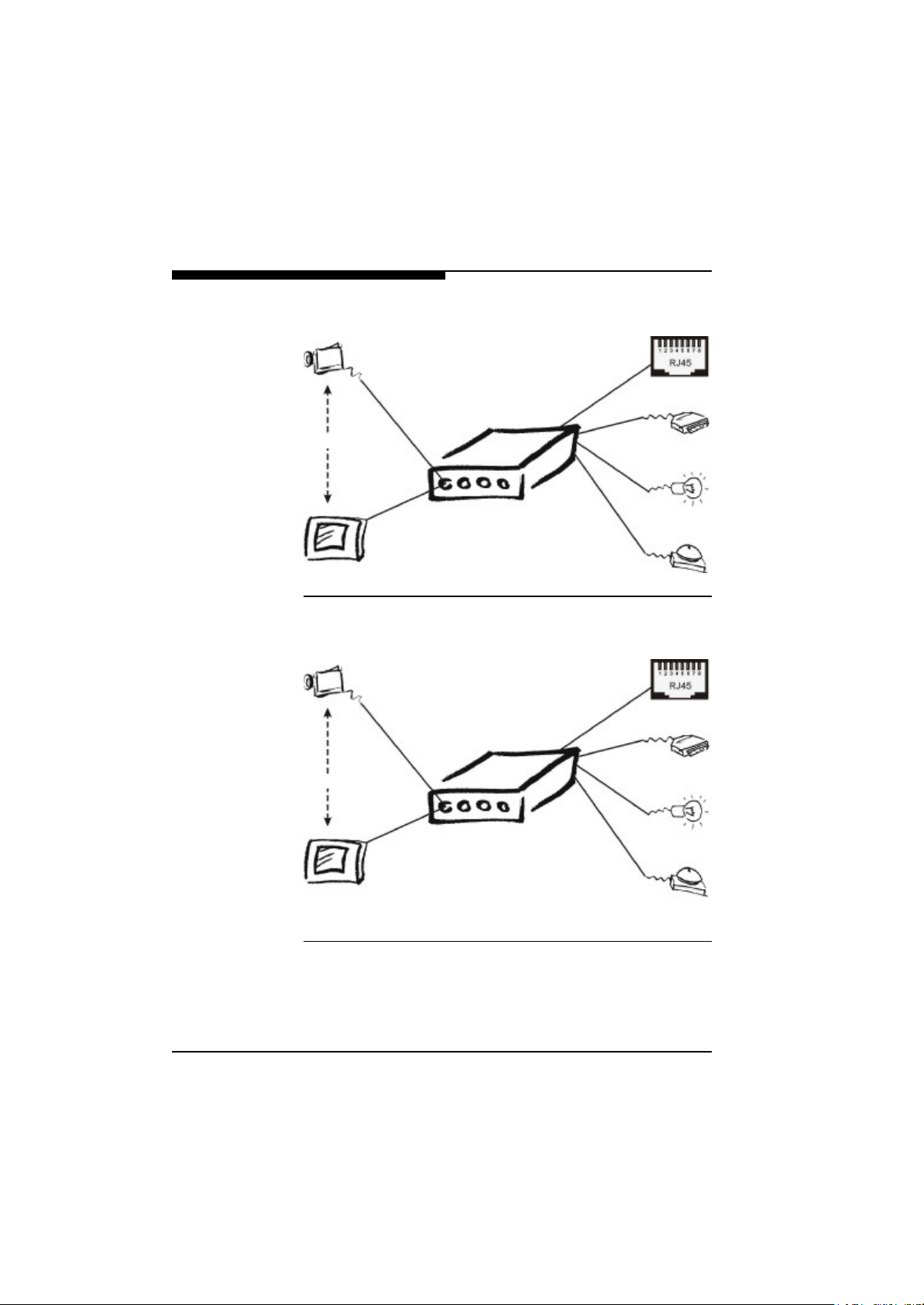
Fig. 2-2 VideoJet X.21 System Concept and Interfaces
Camera
VideoJet G.703
alternative
Serial Interface
Control Output
Control Input
Serial Interface
Control Output
22
Control Input
Monitor
Fig. 2-3 VideoJet G.703 System Concept and Interfaces
VideoJet X.21/G.703 Manual
Page 21

Introduction
To summarize, VideoJet X.21/G.703 enables you to use a
standardized X.21/G.703 leased line for transmission of live video
and audio.
Package Contents
The product package should contain the following items:
l VideoJet
l AC plug power adapter, 5V DC output
l 2 m long 15-pole connecting cable for the X.21 interface
l RJ45 ISDN cable for connection to the G.703 interface
l 3 m configuration cable for connection to a PC
l A diskette with a terminal program
l This manual
F Call your distributor or the dealer if there are any wrong, missing, or
damaged parts.
GSA
or VideoJet
XS/GS
or VideoJet
XEA/GEA
unit with audio option
XE/GE
unit, or VideoJet
XSA/
F Keep the carton, including the original packaging material, to
repack the equipment if there is a need to return it for repair.
VideoJet X.21/G.703 Manual
23
Page 22
Introduction
Front Panel Connectors
One of the VideoJet X.21/G.703 benefits is compact design,
enabling you to install the unit in the most confined environments,
e.g. installation ducts or camera housing. Compact design was
made possible in part by placing connectors at the front and the
rear panel. The front panel connectors are dedicated to the media
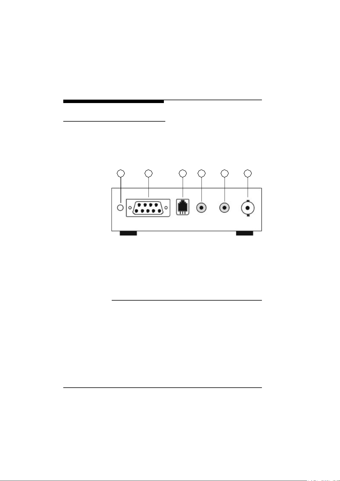
interfaces, i.e. video, audio and data, and are depicted in Fig. 2-4:
1 2 3 4 5 6
Fig. 2-4 VideoJet X.21/G.703 Front Panel Connectors
(1) Green Power LED, blinking when connected to another Vid-
eoJet X.21/G.703 unit
(2) RS-232 transparent data port for connecting to peripheral
equipment
(3) Handset port (only with audio option)
(4) Audio line output (only with audio option)
(5) Audio line input (only with audio option)
(6) Video input (for VideoJet
VideoJet
XE/GE
)
XS/GS
) or video output (for
24
VideoJet X.21/G.703 Manual
Page 23
Introduction
Note that the audio connectors, (3), (4) and (5), are only functional
for units equipped with the optional audio interface. The model
name is appended by the letter “A” for audio in this case: Video-
XSA/GSA
Jet
whereas VideoJet
unit. Otherwise there is no difference in features, therefore all information given for the basic units VideoJet
XE/GE
Jet
denotes a sending unit with installed audio option,
XEA/GEA
denotes the corresponding receiver
XS/GS
and Video-
does also apply to the models with integrated audio
functionality.
The green power LED will be lit as soon as power is supplied to the
unit and the unit is ready for service. During an active connection to
a VideoJet X.21/G.703 unit, the LED will blink to indicate the
connection status.
The serial interface for transparent data transmission does only
provide serial send (pin 3) and receive (pin 2) signals and ground
(pin 5). No hardware flow control signals are provided.
The handset interface facilitates direct connection of a telephone
handset.
Note that either the handset or the line interface is active at any
given time. Selection of the interface is described in Chapter 5.
VideoJet X.21/G.703 Manual
25
Page 24
Introduction
Rear Panel Connectors
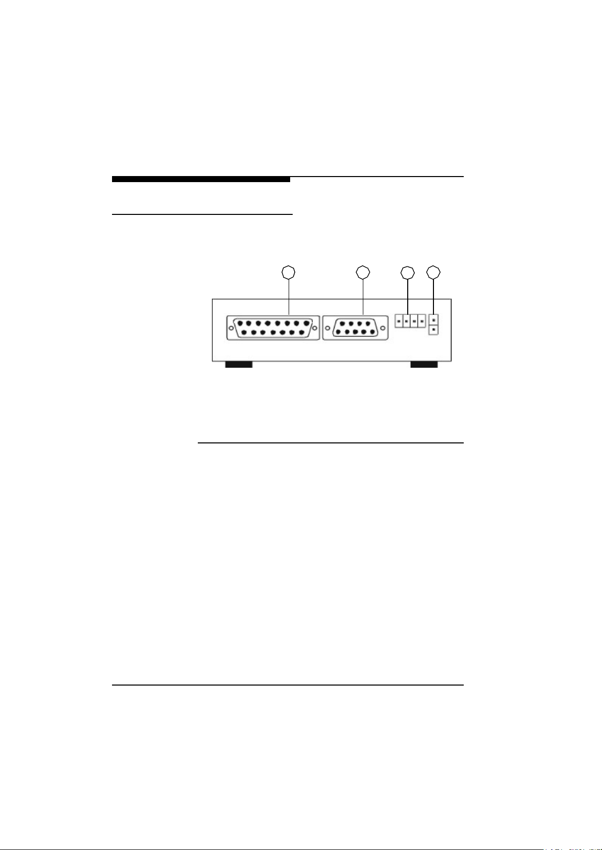
On the rear panel of the unit you will find the X.21/G.703 network
interface, a terminal port for configuration and management with
the NCTerminal program, an I/O-port and the power connector:
1 2 4
(1) X.21 interface (DTE, 15-way SUB-D) for connection with
X.21 DCE
(2) Serial interface for configuration (NCTerminal, RS-232)
(3) Signalling input and relay output
(4) Power connector for connecting the AC plug power adapter
Fig. 2-5 VideoJet X.21 Rear Panel Connectors
3
The power LED on the VideoJet X.21 is the only display that
supplies information about the connection status. But it can be
monitored with the terminal program included in the scope of supply. More detailed information is given in Chapter 5. Most of the
DCEs (data circuit-terminating equipment) of an X.21 leased line
are also equipped with a display that indicates whether data are
being transmitted through the X.21 port.
26
VideoJet X.21/G.703 Manual
Page 25
Introduction
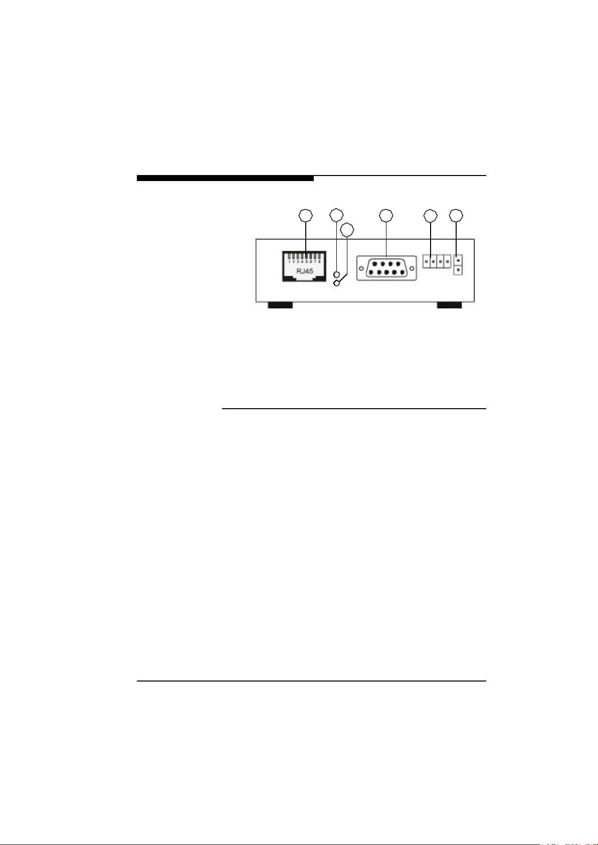
1 4 65
(1) G.703 interface (DTE, RJ45) for connection with G.703 DCE
(2) Yellow TX LED for monitoring packet sending over the ISDN
port
(3) Green LINK LED for link test of ISDN connection
(4) Serial interface for configuration (NCTerminal, RS-232)
(5) Signalling input and relay output
(6) Power connector for connecting the AC plug power adapter
Fig. 2-6 VideoJet G.703 Rear Panel Connectors
2
3
The green LINK LED will provide ISDN status information: If the
LED is on, the ISDN port is properly connected to the ISDN network.
The yellow TX (Transmit) LED will blink for each packet being transmitted. Note that packet reception is not signalled.
The RS-232 interface allows for connection to the serial port of a
PC for simple configuration or for the control of the VideoJet
X.21/G.703 unit. The interface features the full suite of RS-232
flow control signals.
The switching I/O-port allows for direct connection of external signalling devices, for example buttons or contacts. Also, the relay output facilitates switching of peripheral devices, for example lights or
electric door openers.
VideoJet X.21/G.703 Manual
27
Page 26
Introduction
Note: Use only the supplied AC plug power adapter. If the adapter,
the cable or the connector show any sign of damage, do not use the
power adapter and send it in for repair or replacement. Never
attempt to interface any other power adapter other than the supplied one.
Refer to Chapter 4 for a comprehensive discussion of interfacing
peripheral devices to the VideoJet X.21/G.703 unit.
28
VideoJet X.21/G.703 Manual
Page 27

Quick Installation Guide
3
For the fastest route to get your product up and running, just follow
the next 4 steps below:
VideoJet X.21/G.703 Manual
29
Page 28
Quick Installation Guide
Step 1: Connecting a Camera or
Monitor
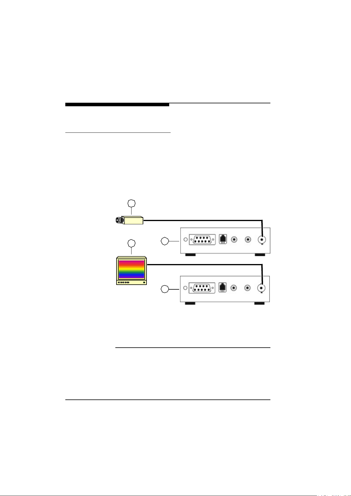
F To connect a camera to the VideoJet
XS/GS
transmitter use a
standard coaxial cable and plug it into the BNC connector at the
front side of the unit. Any video source with a composite PAL or
NTSC output may be used.
F In order to connect a monitor to the VideoJet
XE/GE
receiver use
a standard coaxial cable and plug it into the BNC connector at the
front side of the unit. Any PAL or NTSC video monitor can be used.
1
2
(1) Camera or other video source with composite PAL or NTSC
output
(2) Video Monitor with composite PAL or NTSC input
(3) VideoJet
(4) VideoJet
Fig. 3-1 Connecting a Camera or Monitor
3
4
XS/GS
XE/GE
transmitter
receiver
30
For more information regarding video sources and monitors refer to
the next chapter.
VideoJet X.21/G.703 Manual
Page 29
Quick Installation Guide
Step 2: Connecting to the
X.21 Transmission line
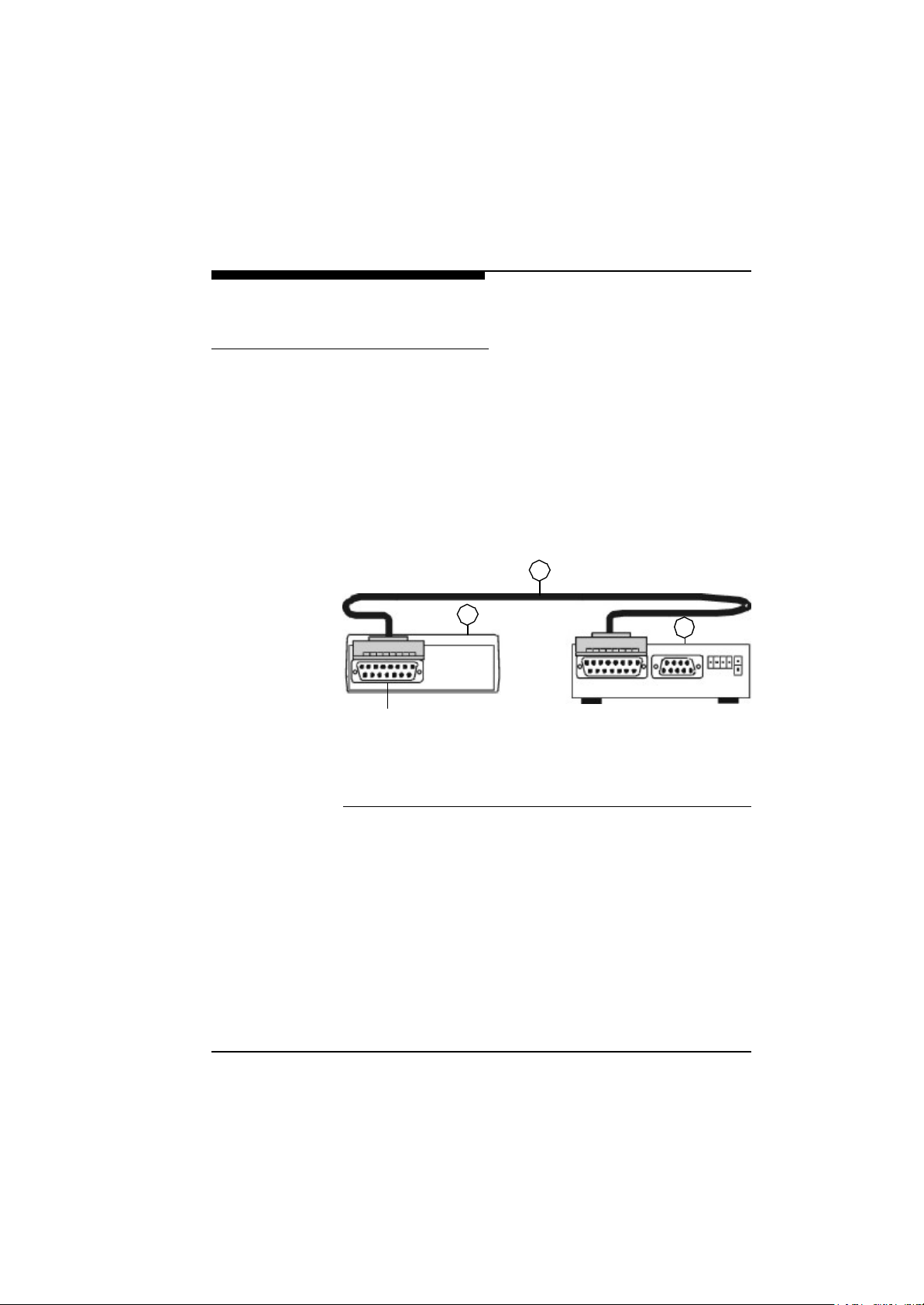
To connect the VideoJet X.21 as a DTE (data terminal equipment) to a DCE (data circuit-terminating equipment) use the delivered 15-pole SUB-D connection cable.
F Plug this cable into the socket labelled “X.21“at the rear side of the
unit.
F Connect the other end of the cable directly with the DCE (data ter-
minal equipment).
A correct connection is shown in Fig. 3-2 below:
2
X.21 Interface
(1) X.21DCE Adapter (data circuit-terminating equipment)
(2) 15-pole SUB-D connection cable for X.21 interface
(3) VideoJetxs transmitter or VideoJetxe receiver
Fig. 3-2 Connecting to the X.21 transmission line
VideoJet X.21/G.703 Manual
1
3
31
Page 30
Quick Installation Guide
Step 2: Connecting to the
G.703 Transmission line
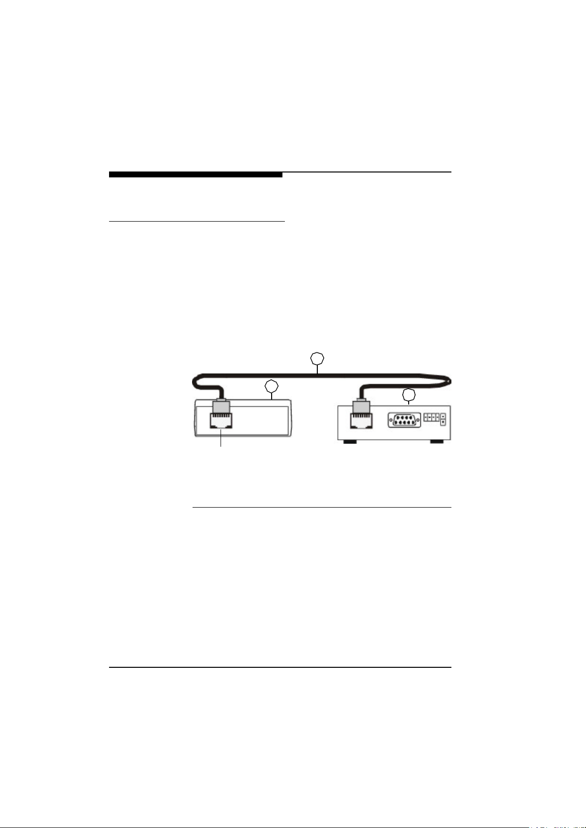
To connect the VideoJet G.703 as a DTE (data terminal equipment) to a DCE (data circuit-terminating equipment) use the delivered RJ45 connection cable.
F Plug this cable into the socket labelled “G.703” at the rear side of
the unit.
F Connect the other end of the cable directly with the DCE (data ter-
minal equipment).
A correct connection is shown in Fig. 3-3 below:
2
1
G.703 Interface
(1) G.703 DCE adapter (data circuit-terminating equipment)
(2) RJ45 connection cable for G.703 interface
(3) VideoJetGS transmitter or VideoJetGE receiver
Fig. 3-3 Connecting to the G.703 Transmission Line
3
32
VideoJet X.21/G.703 Manual
Page 31
Quick Installation Guide
Step 3: Connecting Power
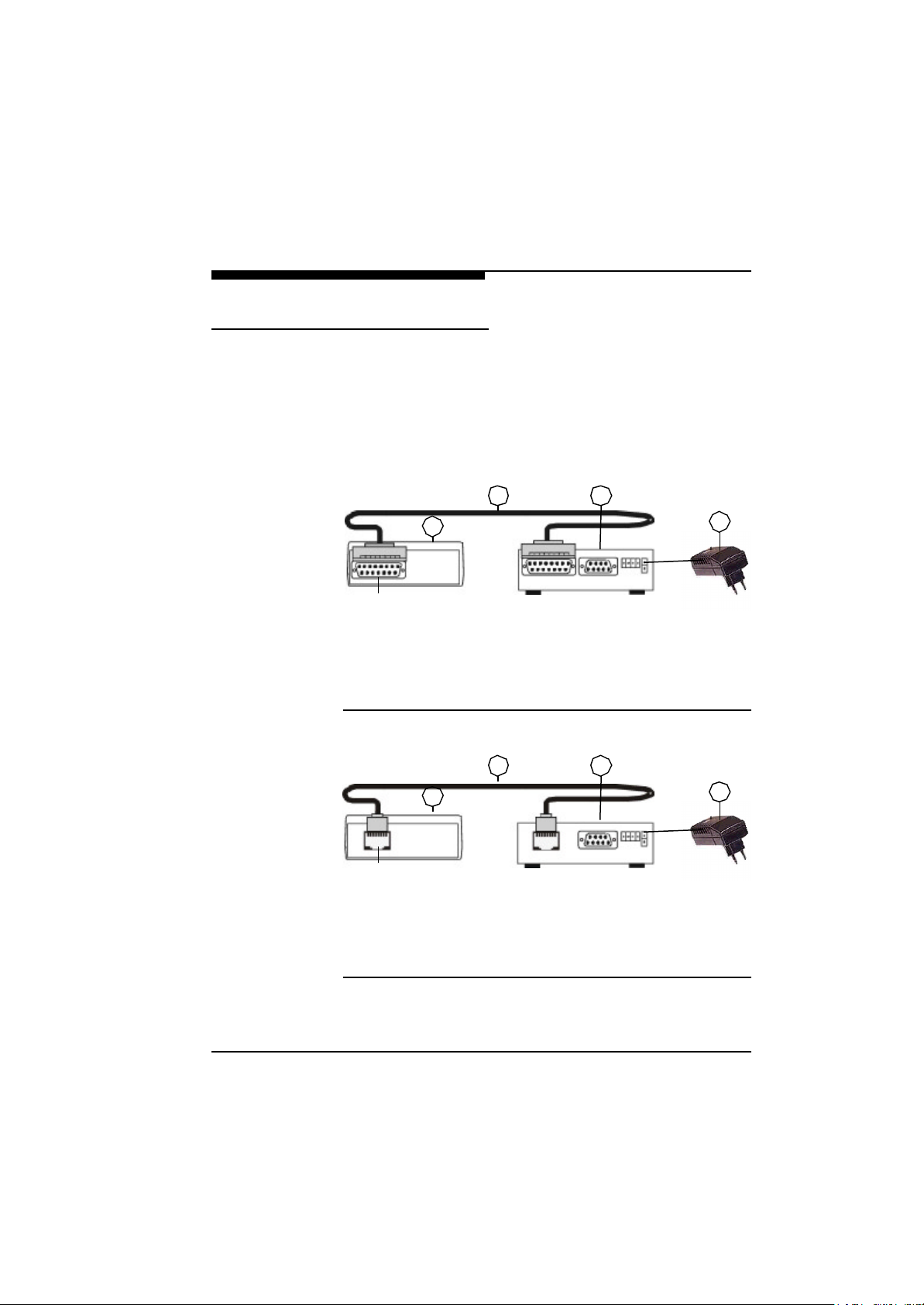
After connecting the video source or the monitor and the X.21/
G.703 cable to the unit, the power adapter has to be attached to the
VideoJet X.21/G.703.
When the power adapter is connected correctly to the VideoJet
X.21/G.703, the green power LED at the front side is lit constantly. If a connection has been established to the remote end, the
power LED blinks. Live video images are transmitted immediately.
X.21 Interface
(1) X.21 DCE adapter (data circuit-terminating equipment)
(2) 15-pole SUB-D connection cable for X.21 interface
(3) VideoJetxs transmitter or VideoJetxe receiver
(4) AC plug power adapter
Fig. 3-4 Connecting Power to the X.21 Interface
32
1
4
G.703 Interface
(1) G.703 DCE adapter (data circuit-terminating equipment)
(2) RJ45 connection cable for G.703 interface
(3) VideoJetGS transmitter or VideoJetGE receiver
(4) AC plug power adapter
Fig. 3-5 Connecting Power to the G.703 Interface
VideoJet X.21/G.703 Manual
32
1
4
33
Page 32
Quick Installation Guide
Connection and therefore transmission of live video images is only
possible if a DCE (data circuit-terminating equipment) is installed at
both ends of the X.21/G.703 leased line. The X.21/G.703 leased
line and the transmission line must be set up and “switched
through”. On most terminal adapters where DCEs are used as the
termination of the X.21/G.703 leased line, it is possible to activate
a loop function. The line can be checked with this function. Please
contact your X.21/G.703 network operator or consult the technical
documentation to check the line.
34
VideoJet X.21/G.703 Manual
Page 33

Hardware Installation
4
The following chapter describes in detail how to connect external
devices to your VideoJet X.21/G.703 system.
Connecting Video Sources or
Displays
F For connecting a camera to the VideoJet
standard coaxial cable and plug it into the BNC connector at the
front panel of the VideoJetes.
Any camera or other video source, e.g. a VCR with a composite
PAL or NTSC output can be connected. VideoJet
colour or B&W sources and automatically detects the standard
(PAL or NTSC). When using VCRs as input source the video quality
can be improved by setting the Input Source in the Video Configu-
ration Page (see Chapter 5) to VCR. The video input is equipped
with an internal termination with 75 Ohms.
F To connect a monitor to a VideoJet
coaxial cable and plug it into the BNC connector at the front panel
of the VideoJet
Any PAL or NTSC video monitor with a composite PAL or NTSC
input can be connected. Moreover a VCR can be connected to
store the received video on a VCR tape.
The default output format is composite PAL.
XE/GE
.
XS/GS
sender, use a
XS/GS
XE/GE
receiver use a standard
accepts
F To switch the video standard at the output to NTSC, change the
video output on the camera configuration page (see Chapter 5) with
NCTerminal.
VideoJet X.21/G.703 Manual
35
Page 34
Hardware Installation
Connecting Audio Equipment
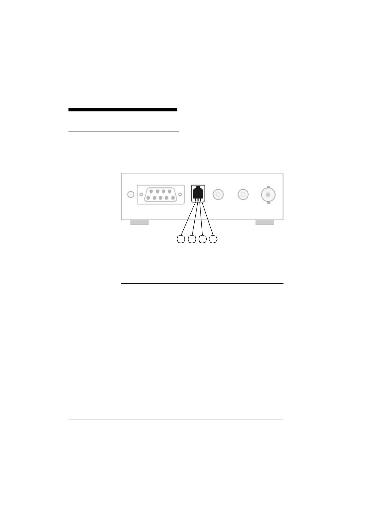
If the VideoJet X.21/G.703 is equipped with the audio option,
basically two audio channels are available, called handset and
audio in/out. Only one of these two audio interfaces can be active
at one time.
(1) Handset Microphone, positive terminal
(2) Handset Speaker, positive terminal
(3) Handset Speaker, negative terminal
(4) Handset Microphone, ground terminal
Fig. 4-1 Pin Assignment
1 2 3 4
36
F A handset can be connected to the RJ11 receptacle labelled Hand-
set at the front panel of the VideoJet X.21/G.703. In order to
select this audio interface check the radio button labelled Handset
in the Audio Configuration Page.
F To select this audio port, check the setting for audio channel 1 or
audio channel 2 on the audio/video configuration page with NCTerminal. Audio channel 2 must be active for the handset.
In this configuration menu you can also select an input and output
level of between 0...255. You can also set the audio coding method
at the sender end under menu item Audio/Video with NCTerminal.
You can select different modes or switch off audio completely. The
audio transmission method can be set on the local device or for the
remote device with the NCTerminal software.
VideoJet X.21/G.703 Manual
Page 35

Hardware Installation
The second audio channel is available at the two cinch receptacles
labelled Audio In and Audio Out at the front panel of the VideoJet
X.21/G.703. To choose this channel the Audio Channel 1 on the
Audio Configuration Page Audio/Video has to be selected. The
level and coding mode settings apply to this channel in the same
manner.
Connecting Data Terminals
VideoJet X.21/G.703 features two serial interfaces, at the
front and the back panel respectively. They serve different purposes and cannot be used interchangeably. The functions of the
terminal port and the transparent data port can be interchanged.
Terminal Port For local control and configuration of the VideoJet X.21/G.703
unit a data terminal (e.g. a PC running a standard terminal program)
can be connected to the serial interface labelled Control Terminal
on the rear panel.
F Use the cable supplied to make the connection.
F Install the program NCTerminal on the PC (see Chapter 5).
F Start the NCTerminal program on the PC.
The 9-pole SUB-D connection provides a standard RS232 assignment that can be connected to the COM port of any PC.
The following interface parameters have default settings and must
be configured accordingly in the terminal program:
l 19200 baud
l 8 data bits
l 1 stop bit
l No parity
VideoJet X.21/G.703 Manual
37
Page 36
Hardware Installation
All the functions and configuration options possible with NCTermi-
nal are described under each of the menus in Chapter 5.
Transparent Data
Port
The second serial interface on the front panel of the VideoJet
X.21/G.703 offers a transparent serial data channel between the
receiver (e.g. COM port of a PC) and the VideoJet
XS/GS
sender.
Typical applications for the transparent data channel are remote
control of peripheral equipment, e.g. pan/tilt/zoom facilities of
selected cameras. In addition this channel can be used for remote
control of any external device with a serial interface. The serial data
is transferred in parallel to the video and audio data.
The following interface parameters are preconfigured and can be
changed with the NCTerminal program:
l 9,600 baud
l 8 data bits
l 1 stop bit
l No parity
Note that transmission of transparent data is enabled only after a
video connection has been established.
Also note that the RS-232 interface for the transparent data port
does not support hardware flow control. If those signals are
required, we recommend replacing the transparent data port with
the NCTerminal port. This special function is described more fully in
Chapter 5 under Interface Configuration.
38
VideoJet X.21/G.703 Manual
Page 37
Hardware Installation
Connecting External Sensors and
Controlling Peripheral Devices
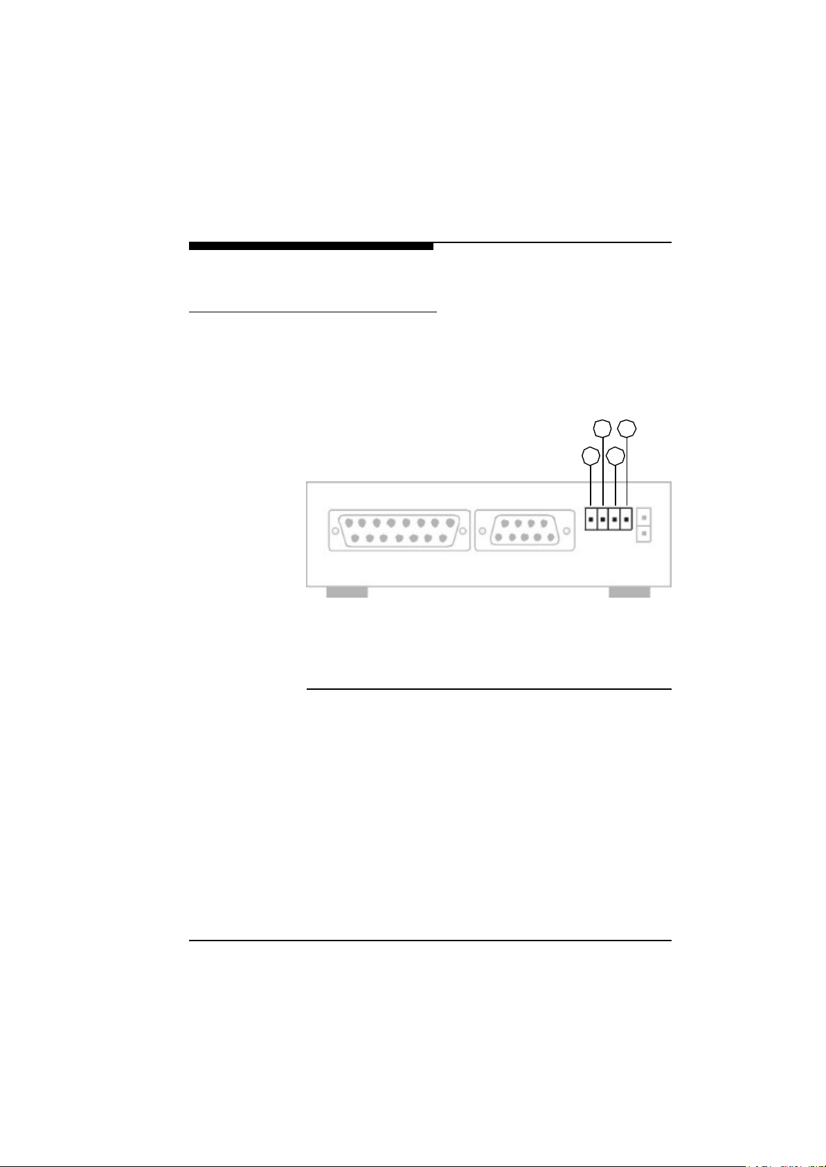
VideoJet X.21/G.703 is equipped with an alarm input to be
used for external signalling devices, like door contacts or motion
detectors. Switches or contacts can be connected directly without a
separate power supply. The signalling input is located on the two
left pins of the detachable screw terminal.
(1) Alarm Input, positive terminal
(2) Alarm Input, ground terminal
(3) Control Output, Relay
(4) Control Output, Relay
Fig. 4-2 Pin Assignment of the I/O Connector
2
1 3
4
The input is activated by connecting pin1 to pin 2. Triggering of an
alarm may be configured to occur upon closing (=active high) or
opening (=active low) the contact between pin 1 and pin 2. If an
alarm occurs, the output relay (for output actions in NCTerminal see
Chapter 5), for example, on the receiving end can be switched or a
text inserted in the picture. For more information about these
options see Chapter 5.
The relay output may be operated interactively, during an active
connection, or automatically to coincide with certain events. The
options available for the relay switching functions can be set on the
configuration page (output actions) of the NCTerminal program. For
example, you can configure a local alarm input in such a way that
VideoJet X.21/G.703 Manual
39
Page 38

Hardware Installation
the output relay at the remote end is activated when the input is triggered.
Typical applications of the relay output are the activation of electric
door openers or the switching of lights and other electrical devices.
Do not exceed the maximum rating of 24 V / 0.5 A.
Connection to the X.21 Leased
Line
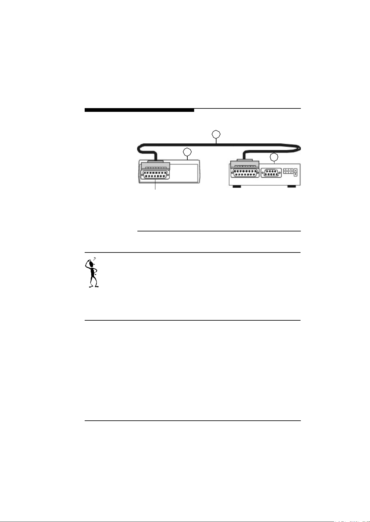
When connecting VideoJet X.21 to a DCE X.21-TA (data circuit-
terminating equipment) for leased lines, the supplied 15-pole SUBD cable (15-pole connector <-> 15-pole connector) must be used.
F To do this, connect the 15-pole connector of interface X.21 to the-
VideoJet X.21.
F Connect the other end of the connecting cable to port of the DCE
X.21-TA (data circuit-terminating equipment).
Once the VideoJet X.21 has been connected to the transmis-
sion line it can be powered from the power supply unit. Only use the
power supply unit included in the scope of supply for the power supply.
The external bit clock required by theVideoJet X.21 is supplied
by the DCE X.21(data circuit-terminating equipment). The X.21 port
of the VideoJet X.21 handles differential signals which are
transmitted according to ITU-T recommendation X.27. The Video-
Jet X.21 synchronizes itself with the external clock and starts to
transmit and receive data through the X.21 port. The X.21 transmission line must operate in full duplex mode.
40
VideoJet X.21/G.703 Manual
Page 39
Hardware Installation
2
1
X.21 Interface
(1) X.21 DCE adapter (data circuit-terminating equipment)
(2) 15-pole SUB-D connection cable for X.21 Interface
(3) VideoJetxs sender or VideoJetxe receiver
Fig. 4-3 Connection Scheme for the X.21 Leased Line
3
Connection and therefore transmission of live video images is only
possible if a DCE (data circuit-terminating equipment) is installed at
both ends of the X.21/G.703 leased line. The X.21/G.703 leased
line and the transmission line must be set up and “switched
through”. On most terminal adapters where DCEs are used as the
termination of the X.21/G.703 leased line, it is possible to activate
a loop function. The line can be checked with this function. Please
contact your X.21/G.703 network operator or consult the technical
documentation to check the line.
VideoJet X.21/G.703 Manual
41
Page 40
Hardware Installation
1234567
8
Assignment of
the Port to X.21/
V.11
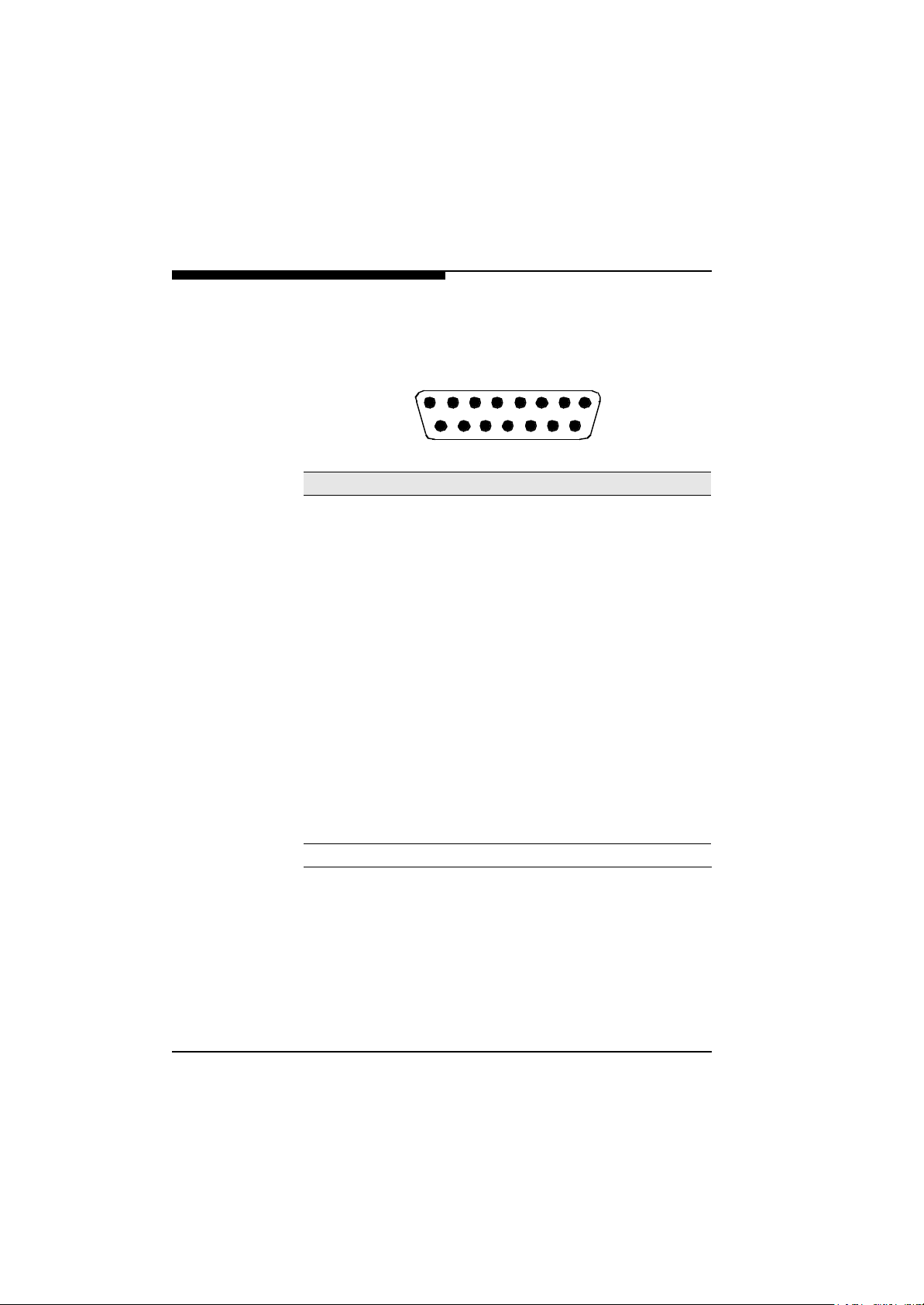
The PIN assignment for sockets and connectors on the X.21 ports
are standardized to ensure compatibility of the devices. The connector assignment for the X.21 port is shown below.
15 14 12 11 1013 9
Pin Function to X.27 Designation to X.24
1 - Shielding
2 T(a)- Transmit
3 C(a)- Control
4 R(a)- Receive
5 I(a)- Signal
6 S(a)- Clock
7 B(a)- Ext. clock (byte clock)
8 G Signal ground
9 T(b)+ Transmit
10 C(b)+ Control
11 R(b)+ Receive
12 I(b)+ Signal
13 S(b)+ Clock
14 B(b)+ Ext. clock (byte clock)
15 - -
Fig. 4-4 Pin Assignment of the X.21 Socket on VideoJet X.21
Some of these signals are optional. However, the following are
mandatory:
l Transmit: T(a) and T(b)
l Receive: R(a) and R(b)
l Clock: S(a) and S(b).
42
VideoJet X.21/G.703 Manual
Page 41
Hardware Installation
Connection to the G.703 Leased
Line
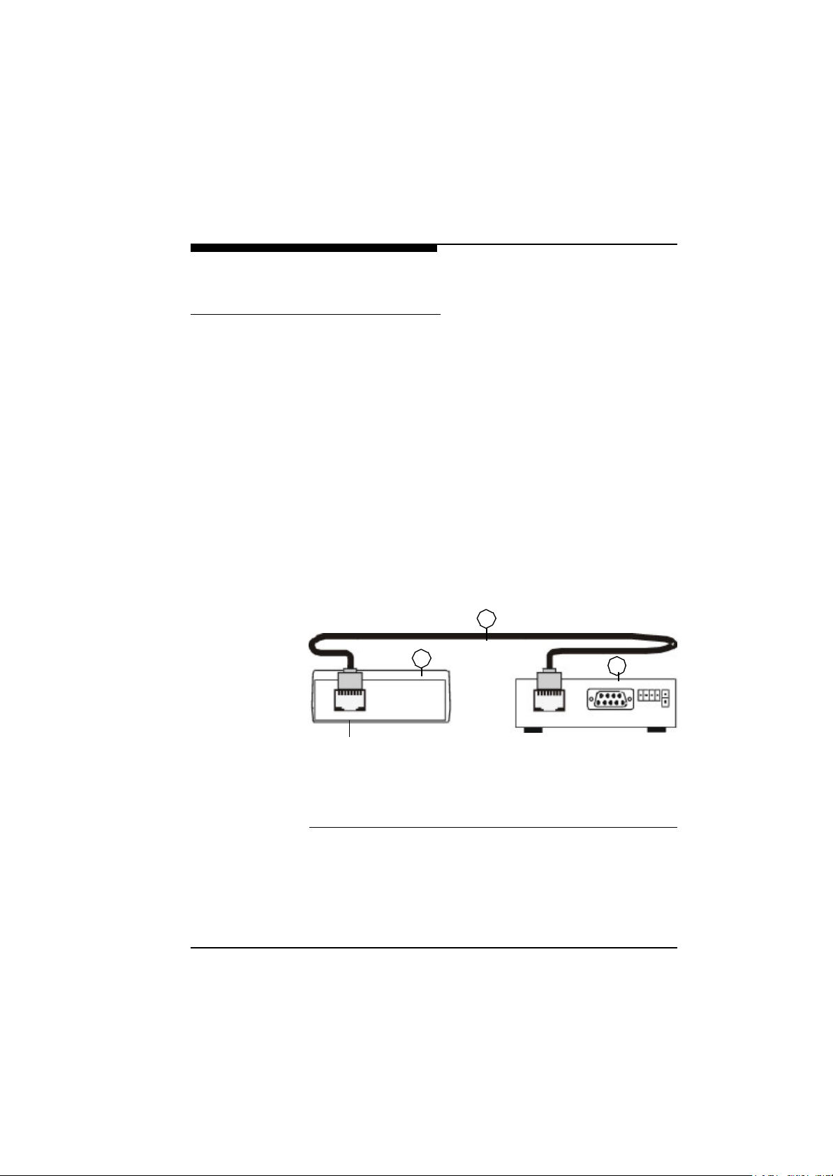
The supplied RJ45 ISDN cable must be used for connecting the
VideoJet G.703 to a DCE G.703-TA (data circuit-terminating
equipment) for leased lines.
F To do that, connect the RJ45 connector of the G.703 port to the Vid-
eoJet G.703.
F Connect the other end of the connecting cable to port G.703 on the
DCE G.703-TA (data circuit-terminating equipment).
Once the VideoJet G.703 has been connected to the transmis-
sion line, it can be connected to the power supply unit. Only use the
power supply unit included in the scope of supply.
The G.703 port of the VideoJet G.703 supplies differential signals that are transmitted according to the ITU-T recommendation
G.703. The VideoJet G.703 synchronizes itself with the external clock and starts to transmit and receive data through the G.703
port. The G.703 transmission line must operate in full duplex mode.
2
G.703 Interface
(1) G.703 DCE adapter (data circuit-terminating equipment)
(2) RJ45 connection cable for G.703 interface
(3) VideoJetGS sender or VideoJetGE receiver
Fig. 4-5 Connection Scheme for the G.703 Leased Line
VideoJet X.21/G.703 Manual
1
3
43
Page 42
Hardware Installation
Connection and therefore transmission of live video images is only
possible if a DCE (data circuit-terminating equipment) is installed at
both ends of the G.703 leased line. The G.703 leased line and the
transmission line must be set up and “switched through”. On most
terminal adapters where DCEs are used as the termination of the
G.703 leased line it is possible to activate a loop function. The line
can be checked with this function. Please contact your G.703 network operator or consult the technical documentation to check the
line.
Assignment of
the Port to G.703
The PIN assignment for the sockets and connectors on the G.703
ports is standardized to ensure compatibility of the devices. Connector assignment of the G.703 port is shown below.
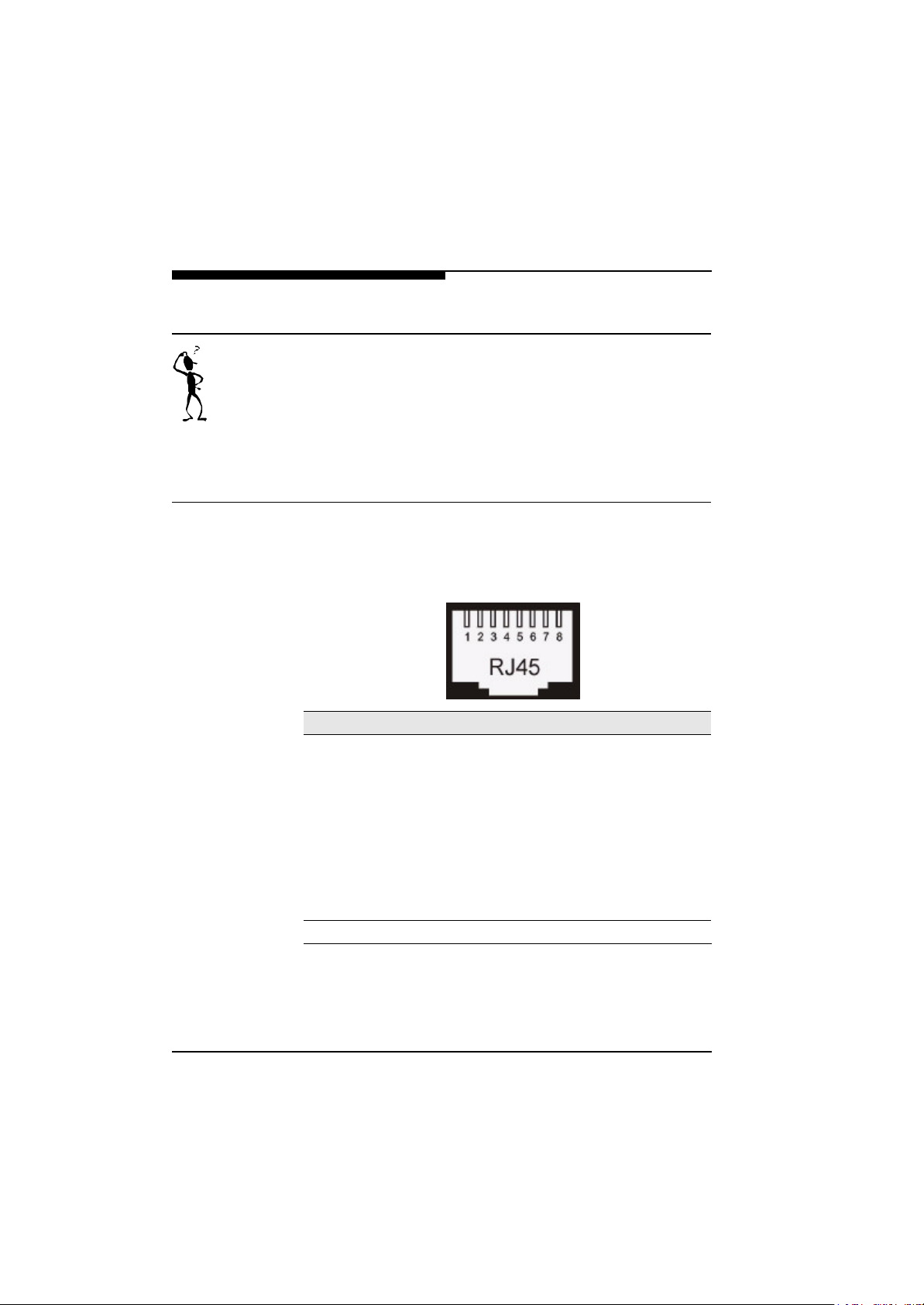
Pin Designation to G.703
1 Receive (RING)
2 Receive (TIP)
3 4 Transmit (RING)
5 Transmit (TIP)
6 7 8 Shielding
Fig. 4-6 Pin Assignment at the G.703 Socket at VideoJet G.703
44
VideoJet X.21/G.703 Manual
Page 43

Configuration with the
5
NCTerminal Software
The configuration and setting options of the VideoJet X.21/
G.703-unit with the supplied software NCTerminal are described
in this chapter. There are two possible ways of configuring the VideoJet X.21/G.703:
l Remote configuration while connected to a remote VideoJet
X.21/G.703
or
l Local configuration without connection, using the NCTerminal
terminal program contained in the scope of supply of the Vid-
eoJet X.21/G.703.
The NCTerminal software allows configuration and control of the
VideoJet X.21/G.703 unit even if no connection to the remote
partner exists. This software is very useful, for instance, if a control
centre with receiving monitors etc. already exists and is to remain
in operation. A VideoJet X.21/G.703 can then be used as a
receiver with video output. The local and remote end can be configured from a single location if connected via the X.21/G.703 line. In
this case, a PC for video playback is not required.
VideoJet X.21/G.703 Manual
45
Page 44
Configuration with the NCTerminal Software
Installation of the NCTerminal
Program
To install the VideoJet X.21/G.703 terminal program under
Windows98, place the installation diskette in the disk drive, start
“Software” in the control panel and select “Install”. The program
then guides you through the installation procedure.
The setup program installs the VideoJet X.21/G.703 Terminal
program in the selected directory and creates an icon.
Starting the Terminal Program
One of the serial ports of the VideoJet X.21/G.703 device is
connected directly to one of the COM ports of the PC using the configuration cable included in the scope of supply. The VideoJet
X.21/G.703 device must not be connected to the power supply
until it has been connected to the PC.
To start the terminal program, click twice on the new icon or start
the program from the file manager or the Windows Explorer. When
the software is started up, the field “Local device” changes to yellow
as soon as a VideoJet X.21/G.703 device has been found and
responds. If the field remains grey, the connection between the Vid-
eoJet X.21/G.703 and the PC, and the PC port setting must be
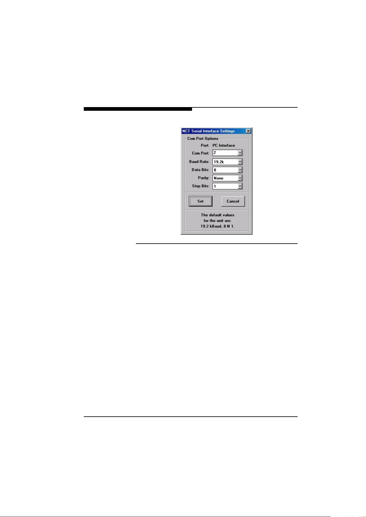
checked. The port parameters can be configured in the system
menu (click with the mouse on the symbol in the top left-hand corner) of the software under “Interface”. It is important to select the
correct COM port.
46
VideoJet X.21/G.703 Manual
Page 45
Configuration with the NCTerminal Software
Fig. 5-1 Configuration of the COM Port
VideoJet X.21/G.703 Manual
47
Page 46
Configuration with the NCTerminal Software
Configuration Options in the Main
Window of NCTerminal
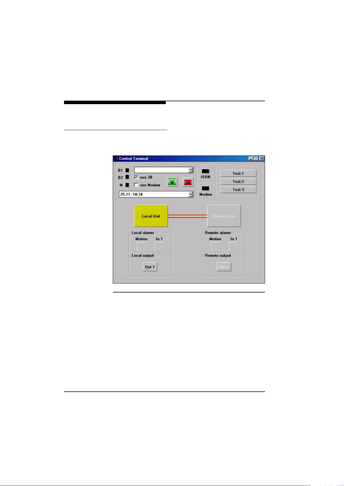
The main window of NCTerminal while a connection with the local
VideoJet X.21/G.703 is active is shown below:
48
Fig. 5-2 Status Display of NCTerminal
The main window of NCTerminal is subdivided into three sections.
The top section displays the connection status. In the central section you can access the configuration pages of the local VideoJet
X.21/G.703. If a connection to the remote partner exists via the
X.21/G.703 leased line, the remote VideoJet X.21/G.703 can
be configured. In the lower section you can see the status of the
alarm inputs and outputs.
VideoJet X.21/G.703 Manual
Page 47

Configuration with the NCTerminal Software
Establishing a
Connection
The connection is established automatically with the VideoJet
X.21/G.703, i.e. there are no alarm call numbers and the func-
tion that only establishes a connection on an alarm does not exist.
As soon as a transmitting and a receiving device are connected to
an existing X.21/G.703 leased line, both devices establish a logic
connection to each other. Video data and all other data are then
sent along this connection.
Once the connection has been established, the system automatically checks whether a VideoJet X.21/G.703 is also con-
nected to the partner. If this is the case, the field “Remote Unit” is
displayed red and you can click on it to check and configure the
remote VideoJet X.21/G.703.
The display next to field ‘M’ shows the status of the X.21/G.703 connection:
Black: No connection
Yellow: Connection being established or disconnected
Green: Connection up
Tab. 5-1 Connection Status Display
If you click on the yellow field “Local Unit” or the red field “Remote
Unit” is already connected you can check and configure the settings
of the connected or linked VideoJet X.21/G.703 system.
These actions are described in more detail below.
Status Displays
of NCTerminal
The user interface of NCTerminal shows the status of the alarm
input and output. It is also possible activate the output by clicking
on the display. This is especially helpful for testing the connected
peripherals. The colour coding of the status display is listed in the
following table:
VideoJet X.21/G.703 Manual
49
Page 48

Configuration with the NCTerminal Software
Yellow: Input or output in idle state
Green: Input or output in active state
Red: Input in alarm state
Tab. 5-2 Status Display for Signal Input and Relay Output
Configuring the
VideoJet X.21/
G.703 Devices
with NCTerminal
By clicking on the icons of the devices, you can configure and operate the local and remote units both locally and remotely. The settings are made on various setting pages that are described in detail
in the following chapter.
50
VideoJet X.21/G.703 Manual
Page 49
Configuration with the NCTerminal Software
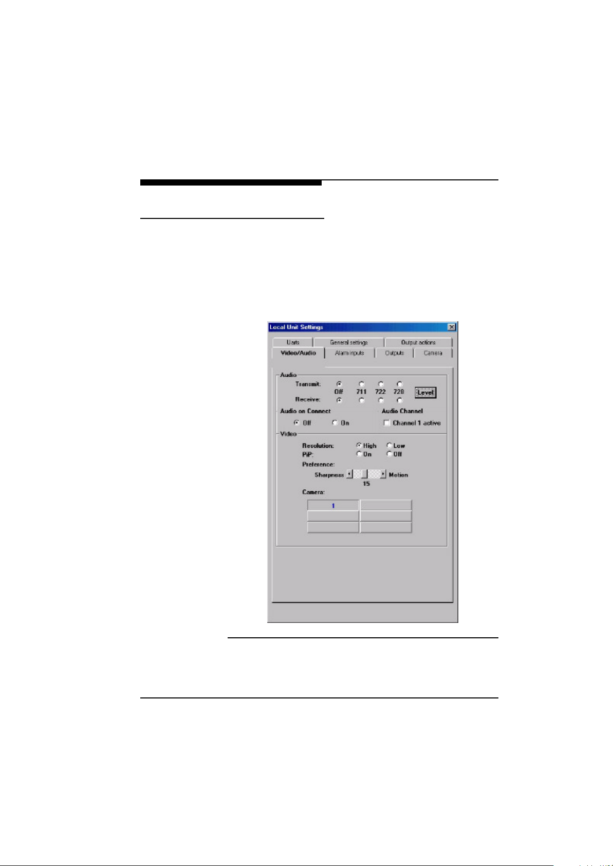
Audio and Video Settings
Unlike the configurations described in later sections which affect
values stored in the device, the video/audio page is mainly used to
control the connected VideoJet X.21/G.703 device. With the
exception of the audio setting for connection and selection of the
audio source these settings are not permanently stored.
The page is subdivided under two headings (audio and video)
which are described in detail below:
Fig. 5-3 Audio and Video Settings
VideoJet X.21/G.703 Manual
51
Page 50

Configuration with the NCTerminal Software
Audio Settings Bidirectional audio transmission is possible with the VideoJet
X.21/G.703 system. This is useful for security applications such
as acoustic surveillance and announcements through to the object
of surveillance. Audio transmission can also be used for other applications, such as door intercom systems.
Because audio data and video data are transmitted in parallel along
the same line, both data flows share the available line capacity.
When audio transmission is activated, the data rate for moving
images is reduced to that of the audio data rate which can result in
reduced video quality (lower frame rate and/or reduced image resolution). VideoJet X.21/G.703 offers several configuration
options to provide the optimum solution for each application, which
are described below.
Various coding methods are available for audio transmission which
differ in terms of audio quality, complexity and the required data
rate. A comparison of the various methods is given in the table
below:
Standard Method Bandwidth Data rate
G.711 PCM 3.1 kHz 56 Kbit/s
G.728 LD-CELP 3.1 kHz 16 Kbit/s
Tab. 5-3 Audio Coding Method
52
The overview above shows that the G.728 standard offers the same
audio bandwidth as G.711 in spite of a reduced data rate. The audio
quality will, however, be somewhat reduced, which may be noticeable in the transmission of music.
In order to achieve a good audio transmission quality, adaptation of
the audio level to the external components used is necessary:
VideoJet X.21/G.703 Manual
Page 51
Configuration with the NCTerminal Software
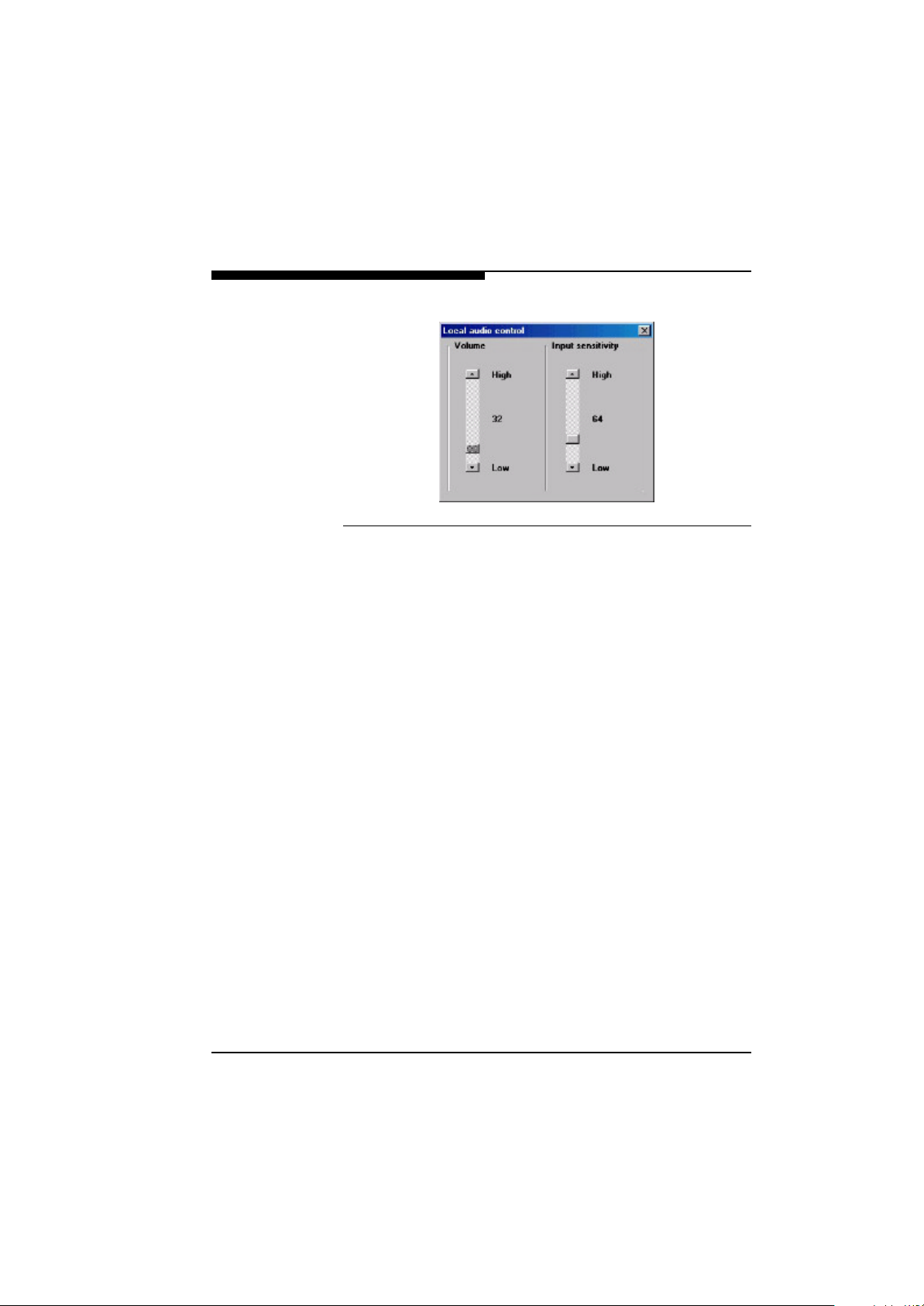
Fig. 5-4 Setting Local Audio Levels
F Click on the button “Level” to call up the dialog displayed above in
which you can configure the audio level. You must adapt the volume
of the received audio signal to the input sensitivity of the connected
power amplifier. In the same way, you must match the sensitivity of
the audio input to the microphone used or generally to the audio
source. The settings you make are stored in the non-volatile memory of the device.
Audio transmission can be switched on and off for both transmission directions independently. You can also configure whether the
VideoJet X.21/G.703 device automatically switches on audio
in the direction transmission as soon as a connection has been
established. Otherwise audio can be switched on later when
required. The bandwidth required for audio transmission is allocated dynamically, so that as soon as audio transmission is
switched off, the data rate previously used for the audio signal is
again occupied by the video. This improves the image quality, especially for low data rates.
VideoJet X.21/G.703 Manual
53
Page 52

Configuration with the NCTerminal Software
Video Settings With the video settings you can alter various image quality param-
eters while a connection exists. First, you can choose between two
resolution levels:
l A high-resolution mode, the “Common Intermediate Format
(CIF)” which provides a local resolution of 288 rows x 352 pixels. This is the default resolution used by VideoJet X.21/
G.703.
l A low-resolution mode, called “Quarter CIF (QCIF)”, with 144
rows x 176 pixels.
Selection of the lower resolution might be suitable when the data
rate is limited and/or, in certain circumstances, a higher image
refresh rate takes priority over a high local resolution. You can
switch from one mode to the other by clicking on the relevant button.
You can use the slider “Preference” to adapt the quality of the video
signal to be transmitted to the requirements of a particular application within broad limits. Moving the slider towards “Sharpness”
improves the resolution of the video. The transmitted frame rate is
reduced but the attention to detail is increased. If more importance
is placed on smooth movements, the slider can be moved towards
‘Motion’. The values displayed below the slider are a reference for
precise retrieval of a particular setting.
54
VideoJet X.21/G.703 Manual
Page 53
Configuration with the NCTerminal Software
Alarm Configuration
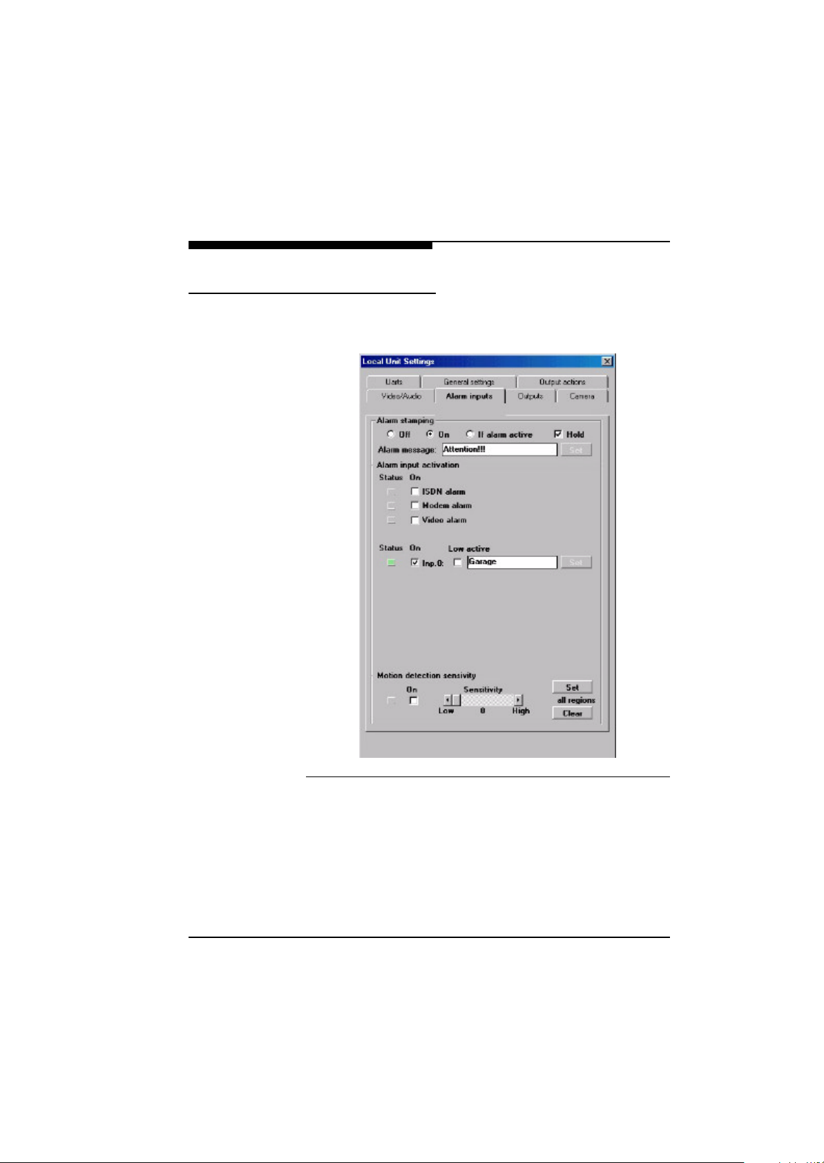
You can control the alarm response of a VideoJet X.21/G.703
unit on the “Alarm inputs” page:
Fig. 5-5 Configuration of the Alarm Inputs
Alarm Stamping In addition to the date, time and name stamping on the video image
described in later sections, it is also possible to display the current
alarm status and a user-configurable text (“Attention!!!” in the example) in the video image of the VideoJet X.21/G.703.
VideoJet X.21/G.703 Manual
55
Page 54

Configuration with the NCTerminal Software
This can be displayed either permanently or only if an alarm occurs.
The option “Hold” allows alarms triggered to remain stored as active
in the display. So even if the original alarm status disappears, the
cause of the alarm is still visible in the video display. Otherwise, the
display reverts to passive as soon as the alarm status disappears.
Alarm Input
Activation
The available alarm sources are listed below the alarm display
described above. Each individual alarm source can be activated by
selecting the “On” field:
Video alarm monitors the input signal of the active camera using
synchronous pulses. If the camera fails an alarm is triggered.
Input contact is used for connecting external detectors. For the
alarm contact you can set whether an alarm is to be triggered in a
closed (High active) or closed (Low active) state. You can assign
any name to the input which describes the external detector, contact or sensor connected, making assignment considerably easier.
The names are stored in the non-volatile memory of the VideoJet
X.21/G.703 device.
Motion detection is an integral part of all VideoJet X.21/
G.703 devices. Its method of functioning and configuration is
described below.
The status display in column “Status” shows the current state of the
alarm and corresponds to the display in the main dialog box of
NCTerminal. The colours signify the following:
Grey: No alarm is activated, alarm triggering is not possible
Green: The alarm is activated and in idle state
Red: The alarm is activated and in alarm status
Tab. 5-4 Activation Display
56
VideoJet X.21/G.703 Manual
Page 55

Configuration with the NCTerminal Software
Motion Detection All VideoJet X.21/G.703 systems can independently monitor
the contents of a video input image and trigger an alarm if a defined
threshold is crossed. Motion detection is activated and deactivated
as described for other alarm sources by clicking on the field “On”.
The sensitivity of motion detection can be adapted to the requirements of the application in question within broad limits. The value
range lies between 1 and 15, where a higher value results in a
higher sensitivity. The value currently set is shown in the display
under the slider with which previous settings can be found again
precisely. The optimum setting for the “Sensitivity” slider can be
found by experimenting. It is important to remember that a higher
sensitivity is also results in unwanted triggering by disturbances in
the picture and thus increases the false alarm rate.
When configuring with NCTerminal, you can only completely set or
completely delete all regions with the “Set” and “Clear” buttons.
Checklist for
Activating Motion
Detection
l You must enter at least one output action and assign it to the
motion detection.
l You must set at least one region.
l You must set the sensitivity correctly.
l You must activate the alarm by selecting the field ‘On’.
l If you are using the master alarm setting, the master alarm
must be active in order to enable the other alarms.
VideoJet X.21/G.703 Manual
57
Page 56
Configuration with the NCTerminal Software
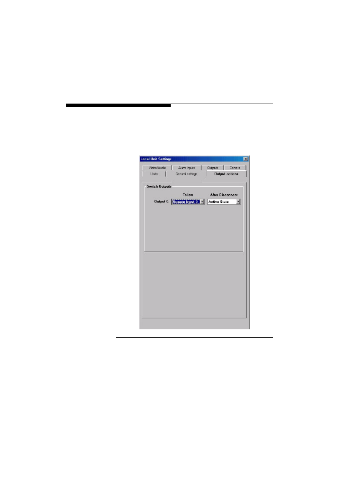
Output Action Depending on your requirements, the response of the available
switch outputs can be adapted to the application. In addition to
manual operation of the relay of the local and/or remote station, the
VideoJet X.21/G.703 systems also feature the powerful option
of automatic switching:
58
Fig. 5-6 Configuration of the Output Action
Events have been defined that automatically trigger switching operations which can then be assigned to a switch output automatically.
The following events are available:
Connection: The output follows the status of the ISDN or modem
connection. Example: Display of an active connection by a lamp.
VideoJet X.21/G.703 Manual
Page 57

Configuration with the NCTerminal Software
Camera 1: The output is activated when a camera is connected.
Example: Switching on the power supply of a connected camera.
Local or remote alarm input: The status of the input is looped
through to an output.
Example: Connection of a buzzer that follows an external sensor.
This means that inputs and outputs of a VideoJet X.21/G.703
<-> VideoJet X.21/G.703 connection can also be crossed so
that the relay follows the input of the remote end.
Alarm sources: In addition to the alarm input mentioned above,
internal alarm sources (video alarm, motion detection) are available
for switching the outputs.
Example: Connection of external signalling for motion detection.
In the second column, the response of each input on disconnection
can be configured. States defined here have priority over all other
existing states once the connection has been terminated. If, for
example, an activated output is operated in monostable mode (see
section below), termination of a connection ends activation of the
output before the time constant has elapsed. The definition of idle
state and active state is given in the next section.
VideoJet X.21/G.703 Manual
59
Page 58

Configuration with the NCTerminal Software
Configuration of the Switching
Output
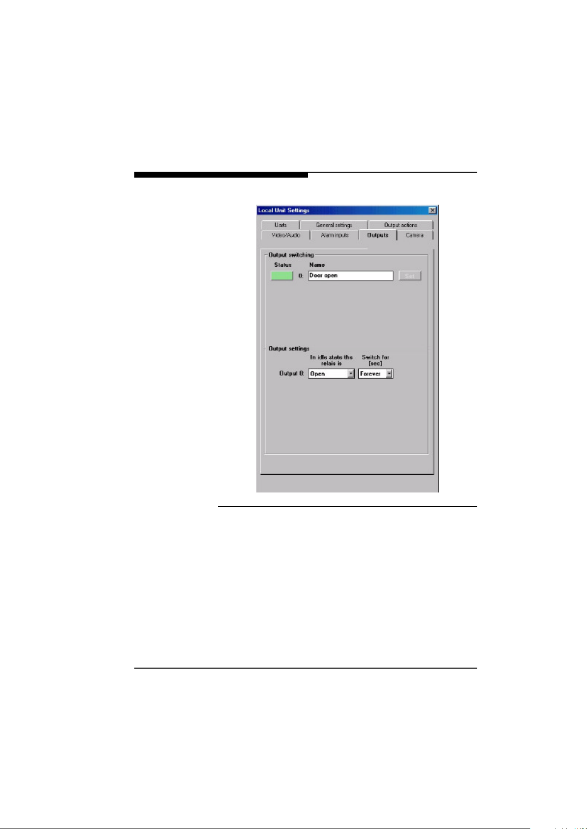
In addition to manual operation of the outputs, configuring of the
switching output on this dialog page also includes the assignment
of individual names and the switching response. The configuration
is stored in the non-volatile memory.
The button on the left-hand side shows the current state of the output. This is displayed in parallel with the information given in the
main window of NCTerminal. The name to the right of the button is
user configurable and can be entered directly in the window.
The outputs can be switched by clicking on the buttons. It is important to remember that the status of the outputs is not stored. When
the device is switched on all outputs are in the idle state.
Individual switching responses are configured in the lower half of
the configuration dialog box. In addition to the idle state definition relay contacts open or closed - it is also possible to set a bistable or
monostable switching response.
Bistable means that the output has two stable states, open and
closed, i.e. remains switched “forever”, unless the status changes
because of a new switching operation.
In monostable operation, idle state is resumed after a settable.
time. The operator does not therefore have to remember to switch
off. Examples of the advantages of monostable output are switching on lighting (automatic staircase lighting, e.g. 2 minutes) or operation of a door opener (e.g. 3 seconds).
60
VideoJet X.21/G.703 Manual
Page 59
Configuration with the NCTerminal Software
Fig. 5-7 Configuration of the Switching Output
Even if the output is configured as shown in the previous dialog, i.e.
to follow the input of the remote end, a monostable switching
response can be used to increase short input impulses. This option
can be used for sensors, for example, that only generate short
impulses (motion detectors, glass breakage sensors). If a sensor of
this type is to be used not only to establish an alarm connection but
also to generate an acoustic signal, a monostable switching
response with a suitably long hold time can also be selected.
VideoJet X.21/G.703 Manual
61
Page 60
Configuration with the NCTerminal Software
Camera Configuration
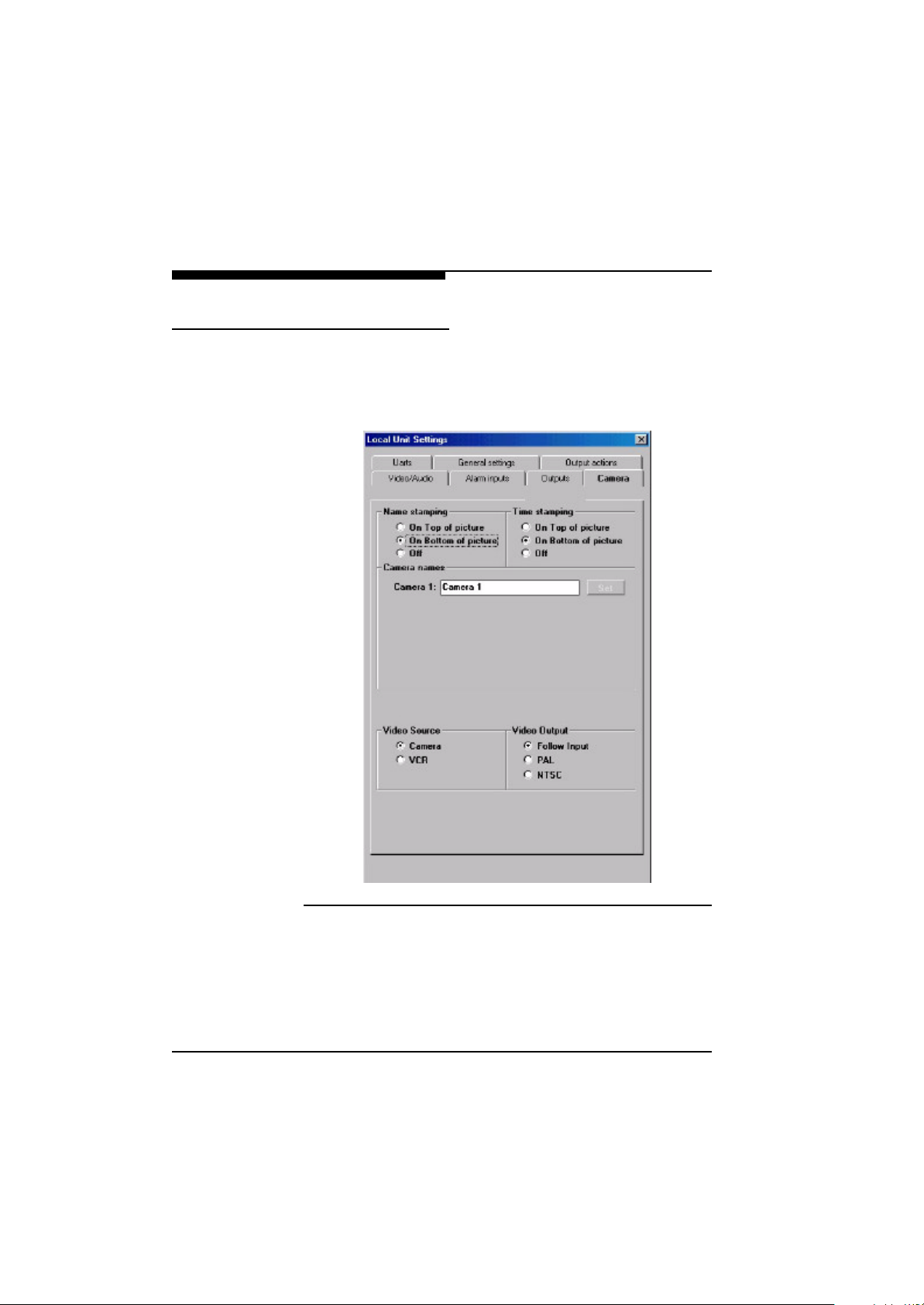
On the “Camera” page of the configuration dialog you can set the
display of the name and date/time as well as the assignment of a
name to the camera channel. This is also where you select the
video standard.
62
Fig. 5-8 Camera Configuration
VideoJet X.21/G.703 Manual
Page 61

Configuration with the NCTerminal Software
Name/Time
Stamping
For quick identification, freely selectable names for the selected
device and the camera currently connected can be displayed in the
video display. The name of the device is separated from the camera
name by a colon. The device name is configured on the page “General settings”.
The name is displayed in the left half of the picture, either at the top
or bottom edge. The date and time supplied by the battery-backed
realtime clock can be displayed at the top or bottom right-hand
edge of the picture.
All insertions are made by the VideoJet X.21/G.703 before
image coding and are therefore an integral part of the transferred
video information. Subsequent manipulation is thus prevented.
Allocation of
Camera Name
The camera name is entered, as already described for alarm inputs
and outputs, by direct entry into a field. Again, the name is stored in
the non-volatile memory and is also used for the camera buttons on
dialog page “Video/Audio”.
Video Standards The reception range of the input switching has been optimized for
operation with video cameras. The picture quality has been
improved by reducing the jitter of the lines to a minimum. Video
recorders usually give greater tolerance in video synchronization.
By selecting the setting “Video recorder” the reception range of the
input switching can be increased and also safely synchronizes
these signals. The video standards “PAL” or “NTSC” are automatically recognized at the input.
It is also possible to explicitly set the video standard of the output
so that simpler monitors that only support one video standard can
be operated. This will be necessary on a receiver if the default setting “PAL” is to be altered. The output setting has no effect on a
sender.
VideoJet X.21/G.703 Manual
63
Page 62
Configuration with the NCTerminal Software
Interface Configuration
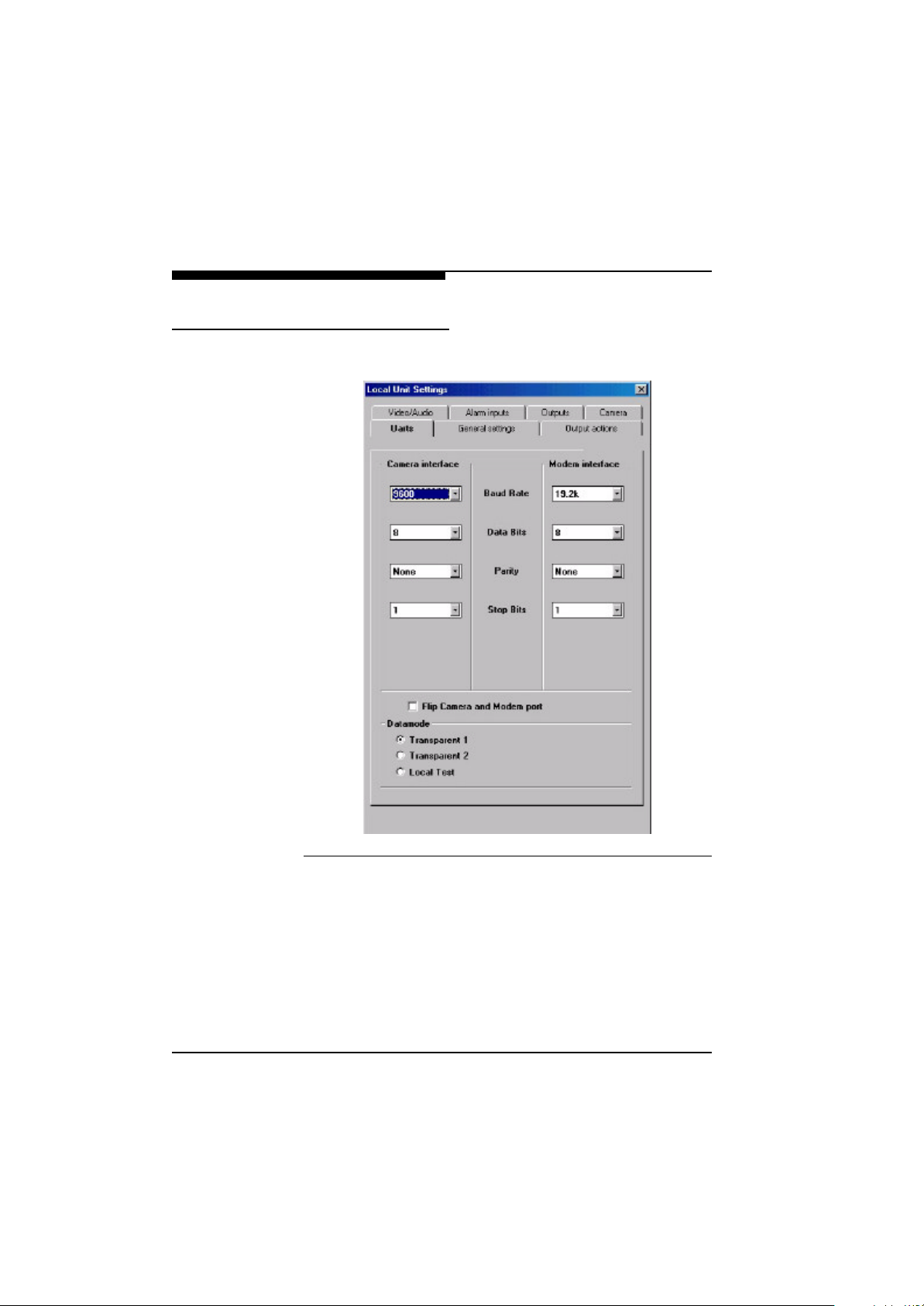
The window below shows the dialog for configuring the interfaces:
64
Fig. 5-9 Interface Configuration
The parameter baud rate, parity and number of data and stop bits
must be set to suit the requirements of the application in question.
If you click on the button “Flip Camera and Modem Port” you can
exchange the functions of both the serial ports. This makes it possible to implement transparent data transmission with flow control
via the terminal port. All signals that are normally output at the camera port are then mirrored at the terminal port and vice versa.
VideoJet X.21/G.703 Manual
Page 63

Configuration with the NCTerminal Software
The settings in the “Data mode” group box define the data transmission between two VideoJet X.21/G.703 devices, i.e. Video-
XS/GS
Jet
sender connected to a VideoJet
transparent data transmission between each of the “camera” ports,
mode “Transparent 1” must be selected.
Unlike transparent mode 1, with “Transparent 2” the binary data of
the remote unit are transmitted with the control commands to a local
NCP device. This option only makes sense if selected in combination with operating devices that support the control protocol NCP.
XE/GE
receiver. For
VideoJet X.21/G.703 Manual
65
Page 64
Configuration with the NCTerminal Software
Common Configuration
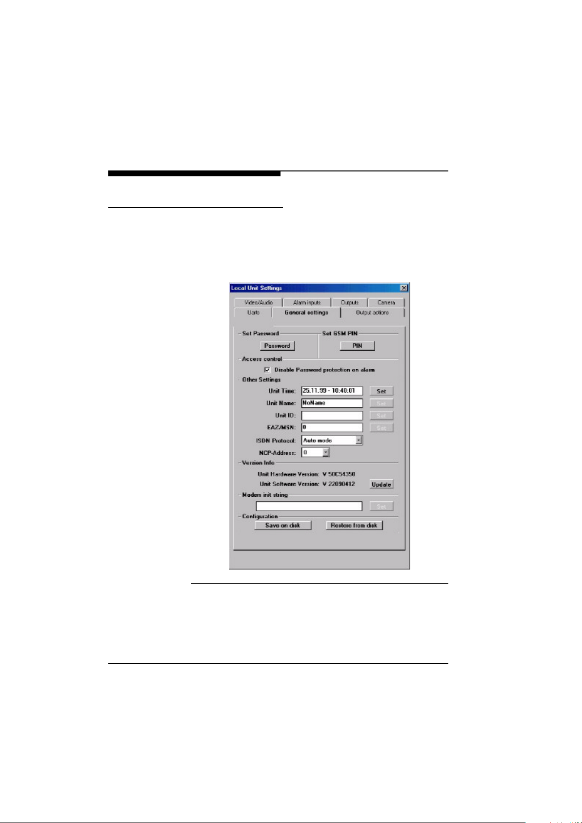
The dialog page “General settings” contains the settings of some of
the basic elements of the VideoJet X.21/G.703 unit. These
include password protection, setting the internal VideoJet X.21/
G.703 clock, and naming of the VideoJet X.21/G.703
device.
66
Fig. 5-10 Common Configuration
VideoJet X.21/G.703 Manual
Page 65

Configuration with the NCTerminal Software
Realtime Clock The VideoJet X.21/G.703 devices have a battery-backed real-
time clock that is set to MEZ at the factory. Readjustment may be
necessary, e.g. if the device is to be operated in a different time
zone or if you want more precise adjustment to your PC clock.
This last action can be performed by clicking on the “Set” button
that transfers the date and time of your PC to the connected Vide-
oJet X.21/G.703 device.
Allocating a
Device Name
In addition to allocating a name to the camera, a name can also be
given to the device. The name could describe the location of the
device or the type of application of the device, to give two possible
examples.
If insertion of the camera name in the video picture has been activated on the dialog page “Camera”, the device name allocated here
is displayed together with the name of the camera, separated by a
colon, in the live picture.
Device Number
(ID)
A number can be allocated for automatic identification of linked
VideoJet X.21/G.703 devices which is read out and checked
as soon as a connection has been established, for example. With
this ID, automatic assignment of incoming alarm calls to the receiving end is possible. This is an advantage, for example, when
devices are operated at different locations.
The device number must only contain numbers and must be no
more than 12 digits long. The configured ID is stored in the non-volatile memory of the device. The ID can be read out during connection without logging on, even if password protection is activated.
Version Display Here, the current version numbers of the hardware and software
are displayed. The hardware number comprises an ID for the
device type, a unique hardware serial number and a revision
number. The firmware number displays the firmware version in the
lower part of the picture. These numbers must be quoted whenever
information about the device is sought.
VideoJet X.21/G.703 Manual
67
Page 66

Configuration with the NCTerminal Software
68
VideoJet X.21/G.703 Manual
Page 67

Advanced Features
6
Apart from the superb video quality and the ease-of-use VideoJet
X.21/G.703 does also sport some advanced features described
in the following.
Automatic Connection Feature
The advantage of conventional dedicated cabling lies in performance guarantee and availability. Automatic connection buildup has
been implemented to allow a connection to be established in the
same way as is possible on analog video cables, simply by plugging
into the X.21/G.703 leased line.
As X.21/G.703 leased lines provide a permanent and steady
stream of data they are extremely suitable for digital video transmission. If the network link is interrupted, an automatic mechanism
ensures that the remote partner is searched for continuously. The
connection is then automatically and autonomously re-established
by the VideoJet X.21/G.703 when the network link is up again.
Once a video transmission has been established by the VideoJet
X.21/G.703, the data flow is only stopped if it is disrupted or the
network link is disconnected.
VideoJet X.21/G.703 Manual
69
Page 68
Advanced Features
Video Motion Detection Feature
The VideoJetes transmitter has the ability to autonomously
check the video input for significant motion in the scene and to trigger an alarm in case the detected motion exceeds a preset threshold. Motion detection is activated with NCTerminal in the dialog
“Alarm inputs” under “Motion detection sensitivity” with the selection button “On” and then confirmed with the “Set” button.
The sensitivity of the motion detector can be selected in the same
menu. This parameter needs to be adapted to the requirements of
the particular application. The best setting should be determined
experimentally.
Note that higher sensitivity will result in a lower robustness against
noise and spurious motion in the scene. This may lead to unwanted
erroneous detections and consequently increase the rate of false
alarms.
The motion detector can be switched on and off and its sensitivity
altered with NCTerminal.
If motion is detected in a picture and an alarm is triggered, it is possible, for example, to switch a relay at the receiving end in order to
trigger an alarm in a surveillance centre.
70
VideoJet X.21/G.703 Manual
Page 69
Advanced Features
Firmware Upload
F Obtain the latest version of the VideoJet X.21/G.703 firmware
F Select the function “General settings“ of the NCTerminal program
F Click on the button “Update“ on this page. Select the appropriate file
The VideoJet units are equipped with Flash EPROMs for
firmware upgradability while the units are in the field. Firmware
upload is accomplished directly on the NCTerminal program within
„General settings“.
Firmware upload using the Web browser is accomplished as follows:
from the Internet (http://www.vcs.com).
Data can only be uploaded when the device is disconnected. Disconnect an existing connection via the X.21/G.703 link.
with the latest firmware using the search button.
F Activate the button “Upload“.
F After about 30 ... 60 seconds you should get a feedback message
from the connected VideoJet unit, that the upload is finished.
Now activate the button “Program”.
F When receiving “ OK” confirms correct upload of the new firmware,
which is now being installed. Installation is indicated by flashing of
the green LED.
.
Under no circumstances should the unit be disconnected from
power while firmware is being installed. Disruption of the reprogramming cycle will damage the Flash EPROM. The unit then has
to be sent in for repair.
VideoJet X.21/G.703 Manual
71
Page 70

Advanced Features
Once reprogramming is complete, the green LED will stop blinking.
F Any attempt to upload an invalid firmware file will result in receiving
the message <upload failed>.
F Once firmware has been successfully uploaded, revisiting the page
“General settings“ yields the version number of the new firmware
appears.
72
VideoJet X.21/G.703 Manual
Page 71

Technical Specification
7
Network Protocol and Standards
Interface X.21,
Configuration NCTerminal
Video coding H.261
Video format CIF (352 x 288), QCIF (176 x 144)
Video frame rate up to 30 frames/second
Audio coding G.711, G.728
Data communication and remote
control
Interfaces at the Videojet
G.703/E1 leased line
H.224
X.21 Interface
G.703 Interface
Video input
(VideoJet
Video output
(VideoJet
Audio input (optional) Cinch, -32 dBm0, adjustable
Audio output (optional) Cinch, -10 to 0 dBm0, 600 Ohms
Handset interface (optional) RJ-11
X.21 Data rate
G.703 Data rate
Data interface RS-232, DB9M
VideoJet X.21/G.703 Manual
XS/GS
XE/GE
15-pole SUB-D socket
RJ45 socket (120 Ohms)
BNC, PAL/NTSC, 75 Ohms, 1 Vss
only)
BNC, PAL/NTSC, 75 Ohms, 1 Vss
only)
64 kbit/s up to 2.048 Mbit/s
2,048 MBit/s
73
Page 72
Technical Specification
Control input Detachable Screw Terminal, for
Relay output Detachable Screw Terminal,
Power Adapter
Type Plug power adapter
Input voltage 100-240 V, 47/63 Hz
Output voltage 5 V , 2,4 A
County specific adapters Europe (default), UK, US, AUS
The physical adapter for the wall outlet is interchangeable for adaptation to different countries. The adapter simply snaps into the plug
power supply. Contact your distributor if you need an adapter for a
different country. For your own safety resist the temptation to open
the power supply and never use a do-it-yourself adapter.
Physical Specification
direct connection of contacts
24 V, 0.5 A
Dimensions 103 x 103 x 33 mm
Weight 0.4 kg (without power supply)
Environmental Specification
Operating temperature 5° to 40° C
Operating humidity 90% maximum relative humidity,
74
noncondensing
VideoJet X.21/G.703 Manual
Page 73

Technical Specification
Electromagnetic Emmissions and
Safety
Meets requirements of EN 55103-1, EN 55103-2,
EN 60950
VideoJet X.21/G.703 Manual
75
Page 74

Technical Specification
76
VideoJet X.21/G.703 Manual
Page 75
Troubleshooting
8
The following instructions will facilitate troubleshooting of frequent
problems. Please contact your dealer or distributor, if the problem
persists after reference to the instructions given here. In this case it
is necessary to mention the serial number noted on the bottom of
the unit and the firmware version.
General Service Remarks
The user should resist the temptation to personally perform repairs
of a VideoJet X.21/G.703 unit. Opening a unit will immediately
void any warranty. Leave all maintenance and repairs exclusively to
qualified technical personnel. Exchange a defective unit with a
replacement unit and send it in for repair.
VideoJet X.21/G.703 Manual
77
Page 76

Troubleshooting
Basic Functioning
The VideoJet X.21/G.703 unit is equipped with one LED which
indicates the operating condition of the unit. The following section
describe in detail malfunctioning indicated by the LED.
Power LED If the green power LED on the front panel of the VideoJet X.21/
G.703 is off and you believe it should be on, check the following
conditions:
l Is the VideoJet X.21/G.703 connected correctly with the
enclosed power supply to the power plug socket?
l Make sure the power supply is properly connected to a func-
tioning power outlet.
l Check the voltage rate of 5 Volt from the power supply. If it is
correctly connected and the green power LED still does not
light you have to exchange the power supply by a new one from
your dealer.
l Check the power cord, if there are any apparent damages.
78
Green Power LED is blinking slowly:
l This does not indicate a malfunction but indicates that a con-
nection is established between another VideoJet X.21/
G.703 unit.
The Power LED stays off after firmware upload and reprogramming:
l If the Power LED does not come back on after a firmware
upload there may have been a problem during upload. Return
the system to your dealer. Closely follow the instruction for the
firmware upload. Especially make sure not to disconnect the
power supply during firmware upload and reprogramming.
VideoJet X.21/G.703 Manual
Page 77

Troubleshooting
Terminal Program In case the terminal program NCTerminal fails to connect to the
VideoJet X.21/G.703 Terminal Port, check:
l Is the right COM-port interface of the PC selected for the termi-
nal program and are the settings correct?
l Is the cable connected to the terminal and not the data port of
the VideoJet X.21/G.703.
l The default settings of 19.200 kbit/s, 8 data bits, no parity, 1
stop bit (8N1) should be programmed for the terminal program
NCTerminal.
l If the data exchange between the terminal program NCTermi-
nal and the VideoJet X.21/G.703 still does not work,
check the serial cable.
Troubleshooting Connection
Problems
If you fail to connect to a VideoJet
receiver VideoJet
pinpoint the problem:
l Be sure not to connect two units of the same type, e.g. receiver
to receiver.
l Check all cable connections.
l Check whether there is a bit clock and that it is within permissi-
ble values.
l Ensure that the X.21/G.703 leased line connection is switched
through.
VideoJet X.21/G.703 Manual
XS/GS
XE/GE
, check the following points in order to
sender from a hardware
79
Page 78

Troubleshooting
Troubleshooting the Video
Connection
If no video or a distorted video image is displayed at the Video-
XE/GE
Jet
VideoJet
l Make sure to use the right VideoJet X.21/G.703 unit for
l Make sure the camera is switched on and the coaxial cable is
l Check the camera cable and connect a video monitor to the
l If a video recorder is connected to the VideoJet
l Check whether the video monitor on the VideoJet
l Check the coaxial cable to the monitor for short circuits or open
l If the monitor only supports one video standard check whether
receiver during a connection to a
XS/GS
your application: a camera can only be connected to a Video-
XS/GS
Jet
connected to the VideoJet
camera in order to check that the latter is functioning correctly.
sender, set the video input source on configuration page “Camera” to VCR.
receiver is switched on and the coaxial cable is connected correctly.
circuits and that the correct input channel is selected on the
monitor.
the correct video standard PAL or NTSC has been set for the
video output on the configuration page Video of the
VideoJet
sender:
sender, never to a VideoJet
XS/GS
sender.
XE/GE
receiver.
XE/GE
receiver!
XS/GS
XE/GE
80
VideoJet X.21/G.703 Manual
Page 79

Troubleshooting
Testing the Audio Connection
This test procedure does only apply to VideoJet
XSA/GEA
eoJet
Test between a VideoJet
GEA
receiver:
l Connect a microphone (via a pre-amplifier) to the Line-In cinch
units with the audio option!
XSA/GEA
sender and a VideoJet
XEA/GEA
or Vid-
XEA/
plug and a loudspeaker to the Line-Out cinch connectors,
respectively, or a handset to the RJ11 plug on both units.
l Make sure that the correct menu items are set in the Audio
Configuration pages of both systems, i.e. select the appropriate interface (line I/O or handset).
l Switch the coding mode to G.711 or G.728.
l Select a non zero volume.
l After establishing the X.21/G.703 leased line connection audio
should be transmitted in both ways.
l Be sure to set the level not too low and to have the right inter-
face selected.
l In case no audio is audible check the microphone and loud-
speaker together with other audio equipment and make sure
the microphone is switched on if it is equipped with a power
switch.
l Check that the correct audio input and handset have been
selected for both devices on the configuration page.
VideoJet X.21/G.703 Manual
81
Page 80

Troubleshooting
82
VideoJet X.21/G.703 Manual
Page 81

Glossary
9
bit/s Bit per second, the actual data rate
CIF Common Intermediate Format, video format with
352x288 pixels
DCE Data Circuit-Terminating Equipment
DTE Data Terminal Equipment
Leased line Unlike a dial-up line, no dialling procedure is necess-
sary for a leased line, because the connection is per-
manent.
Full duplex Simultaneous data transmission in both directions
G.711, G.728 Standard audio coding algorithms defined by ITU-T
H.224 Standardized protocol for data communication and
remote control
H.261 Standard motion video coding algorithm defined by
ITU-T
ID Identification: machine readable number or name
IEEE Institute of Electrical and Electronics Engineers
Parameter Values used for the configuration of the VideoJet
X.21/G.703 system
Picture A video picture that has been digitized at a given
resolution
QCIF Quarter CIF, Video format with 176x144 pixels
V.24, RS-232 A list of definitions for the transmission between DTE
and DCE
X.21 Standardized interface between DTE and DCE for
synchronous data networks
G.703 ISDN interface between DTE and DCE for worldwide
traffic networks
VideoJet X.21/G.703 Manual
83
Page 82

Glossary
84
VideoJet X.21/G.703 Manual
Page 83

Index
10
Numerics
120 Ohm 73
75 Ohm 35, 73
A
AC plug power adapter 28
Adaptation, dynamic 21
Alarm contact 56
Alarm input 59
Alarm text display 56
Audio coding 73
Audio input 73
Audio level 52
Audio option 19, 36
Audio output 73
Audio transmission 52
Automatic connection 69
B
Bistable 60
Bit clock 40, 79
BNC 73
BNC connector 35
C
Camera name 63
Configuration cable 23, 46
Configuration of the switching output 60
Configuring the interfaces 64
VideoJet X.21/G.703 Manual
85
Page 84

Index
Connectors 24
Control input 74
County specific adapters 74
D
Data circuit-terminating equipment 40, 43
Data interface 73
Data rate 52, 53
Device name 63, 67
E
Establishing a connection 69
F
Firmware upgrade 71
Flash EPROM 71
G
86
G.703 data rate 17, 73
G.703 port 17, 19, 21, 23, 43, 44, 73
H
Handset interface 25, 73
Handset interface, pin assignment 36
Hardware flow control 25
I
ID 67
Idle state of the switching output 60
Image quality 54
Installation 46
Interface 25
Interface parameters, preconfigured 37, 38
Interfaces 24
VideoJet X.21/G.703 Manual
Page 85

Index
Intranet 13
L
Leased line 17, 19, 79
Local device 36, 46, 48, 65
Local station 58
Local unit 49, 50
Loop function 34, 41
M
Monostable 60
Motion detection 57
Motion detector 70
N
NTSC 35, 63
O
Output actions 39
P
PAL 35, 63
Pan/tilt/zoom cameras 19
Port 26, 36
Purpose of this Manual 13
R
Realtime clock 63, 66, 67
Refresh rate 54
Relay output 39, 74
Remote configuration 45
Remote device 36
Remote station 58
Remote unit 49, 65
VideoJet X.21/G.703 Manual
87
Page 86

Index
Remote video surveillance 20
Resolution (CIF) 54
RS-232 interface 37, 38
S
Sensitivity, motion detector 70
Serial interface RS-232 27
Serial interface, RS-232 37
Serial interface, terminal port 37
Serial interface, transparent data interface 38
Signalling devices 27
Switch output 58
Switching response 60, 61
T
Terminal program 17, 26, 46
Text display 62, 63
Text insertion 55
Transmission speed 17
Transparent data transmission 65
Transparent data, transmission of 25, 38
Troubleshooting 77
88
V
Version number 67
Video coding 73
Video format 73
Video frame rate 73
Video input 73
Video monitor 80
Video motion detector 70
Video output 73
Video recorder 63
Video ring buffer 20
Video settings 54
Video standard 35, 62, 63, 80
VideoJet X.21/G.703 Manual
Page 87

Index
X
X.21 data rate 17, 73
X.21 port 17, 18, 21, 23, 40, 42, 73
VideoJet X.21/G.703 Manual
89
Page 88

Index
90
VideoJet X.21/G.703 Manual
Page 89

VideoJet X.21/G.703 Manual
91
Page 90
VCS Video Communication Systems GmbH
Forchheimer Straße 4 , 90425 Nürnberg Germany
Phone: +49 911 93456 0 Fax: +49 911 93456 66
http://www.vcs.com
ID-Nr.: 7096/1299/0/1
 Loading...