

VCS VideoJet 100, C 100, 100 Series, VideoJet 400 19"", VideoJet 400 User Manual

VCS
100series
Manual for
C 100
VideoJet 100
VideoJet 400
VideoJet 400 19’’

Copyright
This manual is the intellectual property of VCS and is protected by
copyright. All rights are reserved. No part of this document may be
reproduced or transmitted for any purpose, by whatever means, be
they electronic or mechanical, without the express written permission of VCS.
Edition: December 2002 (Version 6.0)
© Copyright 2002 VCS Video Communication Systems AG
Note
Trade m arks
This manual was compiled with the greatest of care and all information double checked. At the time of printing the description was
complete and correct. Because of the further development of products, the content of the manual might change without prior notice.
VCS will not be liable for damage which is directly or indirectly due
to errors, incompleteness, or discrepancies between the manual
and the product described.
All names used in this manual for hardware and software are very
probably registered trade marks and must be treated as such.

Content
Content . . . . . . . . . . . . . . . . . . . . . . . . . . . . . . . . . . . . . . . . . . . . 1
Chapter 1 Preface . . . . . . . . . . . . . . . . . . . . . . . . . . . . . . . . . . . . . . . . . . . . 5
Conventions . . . . . . . . . . . . . . . . . . . . . . . . . . . . . . . . . . . . . . . . 5
Intended use . . . . . . . . . . . . . . . . . . . . . . . . . . . . . . . . . . . . . . . . 7
EU Guidelines . . . . . . . . . . . . . . . . . . . . . . . . . . . . . . . . . . . . . . . 7
Rating plate . . . . . . . . . . . . . . . . . . . . . . . . . . . . . . . . . . . . . . . . . 7
Chapter 2 Safety information . . . . . . . . . . . . . . . . . . . . . . . . . . . . . . . . . . . 9
Electrical shock hazard . . . . . . . . . . . . . . . . . . . . . . . . . . . . . . . . 9
Installation and operation . . . . . . . . . . . . . . . . . . . . . . . . . . . . . 10
Repairs and maintenance . . . . . . . . . . . . . . . . . . . . . . . . . . . . . 10
Chapter 3 Product description . . . . . . . . . . . . . . . . . . . . . . . . . . . . . . . . 11
Scope of delivery . . . . . . . . . . . . . . . . . . . . . . . . . . . . . . . . . . . . 11
Preconditions for commissioning . . . . . . . . . . . . . . . . . . . . . . . 12
Preconditions for configuration . . . . . . . . . . . . . . . . . . . . . . . . . 12
Preconditions for operation . . . . . . . . . . . . . . . . . . . . . . . . . . . . 12
Overview of functions . . . . . . . . . . . . . . . . . . . . . . . . . . . . . . . . 13
Connectors, controls and LEDs . . . . . . . . . . . . . . . . . . . . . . . . 20
Chapter 4 Installation . . . . . . . . . . . . . . . . . . . . . . . . . . . . . . . . . . . . . . . . 29
Installing the
Lens . . . . . . . . . . . . . . . . . . . . . . . . . . . . . . . . . . . . . . . . . . . . . 30
Further connections . . . . . . . . . . . . . . . . . . . . . . . . . . . . . . . . . 32
Installing the
C 100
. . . . . . . . . . . . . . . . . . . . . . . . . . . . . . . . . . 29
VideoJet 100
. . . . . . . . . . . . . . . . . . . . . . . . . . . . 34
VCS 100series
1

Content
Connections . . . . . . . . . . . . . . . . . . . . . . . . . . . . . . . . . . . . . . . 35
Installing
VideoJet 400
. . . . . . . . . . . . . . . . . . . . . . . . . . . . . . . 39
Cabinet installation . . . . . . . . . . . . . . . . . . . . . . . . . . . . . . . . . . 40
Connections . . . . . . . . . . . . . . . . . . . . . . . . . . . . . . . . . . . . . . . 41
Switching on / Switching off . . . . . . . . . . . . . . . . . . . . . . . . . . . . 45
Commissioning
with terminal program . . . . . . . . . . . . . . . . . . . . . . . . . . . . . . . . 46
Chapter 5 Configuration with
web browser . . . . . . . . . . . . . . . . . . . . . . . . . . . . . . . . . . . . . . 49
Making the connection . . . . . . . . . . . . . . . . . . . . . . . . . . . . . . . 49
Selecting the configuration mode . . . . . . . . . . . . . . . . . . . . . . . 50
Installation wizard . . . . . . . . . . . . . . . . . . . . . . . . . . . . . . . . . . . 51
Expert Mode . . . . . . . . . . . . . . . . . . . . . . . . . . . . . . . . . . . . . . . 55
Function test . . . . . . . . . . . . . . . . . . . . . . . . . . . . . . . . . . . . . . . 95
Chapter 6 Operation . . . . . . . . . . . . . . . . . . . . . . . . . . . . . . . . . . . . . . . . . 97
Operation with
MS Internet Explorer . . . . . . . . . . . . . . . . . . . . . . . . . . . . . . . . . 97
Making and storing snapshots . . . . . . . . . . . . . . . . . . . . . . . . . 100
Storing MPEG sequences . . . . . . . . . . . . . . . . . . . . . . . . . . . . 101
Replay of DRAM recordings . . . . . . . . . . . . . . . . . . . . . . . . . . 101
Backup . . . . . . . . . . . . . . . . . . . . . . . . . . . . . . . . . . . . . . . . . . 104
Hardware connections
between VCS Units . . . . . . . . . . . . . . . . . . . . . . . . . . . . . . . . . 105
Operation with Software-Decoder . . . . . . . . . . . . . . . . . . . . . . 106
Chapter 7 Care and Service . . . . . . . . . . . . . . . . . . . . . . . . . . . . . . . . . . 107
Checking the network . . . . . . . . . . . . . . . . . . . . . . . . . . . . . . . 107
Maintenance . . . . . . . . . . . . . . . . . . . . . . . . . . . . . . . . . . . . . . 107
Further sale, disposal . . . . . . . . . . . . . . . . . . . . . . . . . . . . . . . 108
2
VCS 100er Serie

Content
Chapter 8 Annex . . . . . . . . . . . . . . . . . . . . . . . . . . . . . . . . . . . . . . . . . . . 109
Faults – possible causes and remedy . . . . . . . . . . . . . . . . . . . 109
C 100
LEDs
LEDs
LEDs
. . . . . . . . . . . . . . . . . . . . . . . . . . . . . . . . . . . . . . . 111
VideoJet 100
VideoJet 400
. . . . . . . . . . . . . . . . . . . . . . . . . . . . . . . . 112
. . . . . . . . . . . . . . . . . . . . . . . . . . . . . . . . 113
Glossary . . . . . . . . . . . . . . . . . . . . . . . . . . . . . . . . . . . . . . . . . 114
Specifications . . . . . . . . . . . . . . . . . . . . . . . . . . . . . . . . . . . . . 117
Chapter 9 Index . . . . . . . . . . . . . . . . . . . . . . . . . . . . . . . . . . . . . . . . . . . . 125
VCS 100series
3

Content
4
VCS 100er Serie
Preface
1
Conventions
These Installation and Operating Instructions are intended for persons authorised to install and operate a
This series consists of the IP camera
Servers
natives. International, national and any relevant regional regulations relating to electronics must be observed at all times. The
Operating Instructions explain the installation and operation of all
VCS 100series
In this manual, the following symbols and notations are used to
draw attention to special situations:
Hazard! or Attention!
This symbol indicates that failure to follow the safety instructions
given may directly endanger people, cause damage to the system
or to other equipment. The symbol represents a direct threat of danger.
VideoJet 100
devices.
VideoJet 400
and
VCS 100series
C 100
and the Network Video
including all device alter-
device.
VCS 100series
Note
This symbol indicates tips and notes that make using the device
easier and more convenient.
5

Preface
Note
This symbol indicates that you might have to find out special information to be able to make the settings or start up the system correctly.
The following typographic conventions are used in this manual:
Configuration
Menu names and window and key names and
parameters
[Enter], [C] Key names
[Ctrl] + [C] Two or more keys that are pressed simul-
taneously.
ping Command line input and output
The description is based on the
VideoJet 100
resp.
C 100
VideoJet 400
. Only where
differ regarding basic functions these
particularities are specified.
6
VCS 100series

Intended use
Preface
EU Guidelines
The IP camera
via data networks (Ethernet LAN).
The Network Video Servers
to transmit video, audio and control signals via data networks (Ethernet LAN).
All devices are designed for use in CCTV systems. The connection
of an external alarm generator allows various functions to be triggered automatically. Other applications are not permitted.
In the event of questions concerning the use of the device which are
not answered in this manual, please contact:
VCS Video Communication Systems AG
Forchheimer Straße 4
90425 Nürnberg, Germany
Phone +49 (0) 911 93 45 6-0
Fax +49 (0) 911 93 45 6-66
info@vcs.com
The IP camera
VideoJet 400
and
Guidelines 89/336 (Electromagnetic Compatibility) and 73/23,
amended by 93/68 (Low-Voltage Guideline).
C 100
serves to transmit video and control signals
VideoJet 100
C 100
and the Network Video Servers
comply with the specifications of European
VideoJet 400
and
VideoJet 100
serve
Rating plate
VCS 100series
For exact identification, you will find the model designation and
serial number on the rating plate on the bottom of the housing.
Please note this information here before installation in order to have
it on hand in the event of queries or spare parts orders.
7

Preface
8
VCS 100series

Safety information
2
Electrical shock hazard
!
Never attempt to connect the unit or the mains power supply to
any power network other than the one for which it was intended.
!
Use only appropriate and approved power supply units for the
C 100
plied with the
!
Do not open the housing of the power supply unit.
!
Disconnect the power supply unit from the mains power supply
and from all other devices if a fault occurs.
!
Install the power supply unit and the unit only in a dry place
protected against the elements.
!
If you are uncertain about the safe operation of the unit, shut it
down immediately and secure it to prevent any unauthorised
start-up. Safe operation is no longer possible, for example,
– if damage is visible to the unit or the cables,
– if the unit no longer operates correctly,
– if the unit has been exposed to rain or moisture,
– if objects have penetrated inside the unit,
– after long storage under improper conditions or
– after heavy demands during transport.
Have the system checked by VCS in such cases.
(see technical specifications) resp. the mains lead sup-
VideoJet 100
and the
VideoJet 400
.
VCS 100series
9
Safety information
Installation and operation
!
All applicable electrical codes and regulations must be observed
and followed at all times during the installation.
!
Before installing or operating the system, ensure that you have
read and understood the documentation for other equipment
connected to the unit, e.g. monitors or pan-and-tilt heads. These
contain important safety notices and information concerning permissible applications.
!
Perform only the installation and operating work described in this
manual. All other work beyond this may lead to injuries to persons and damage to the system or other equipment.
!
Ensure a secure footing whenever working in elevated positions
(e.g. under the ceiling, on masts, etc.). Use only safety ladders.
If necessary, use a safety harness or railings.
Attention!
Close to high frequency electromagnetic fields the audio output
signal of the
VideoJet
units may be distorted.
Repairs and maintenance
!
Never open the housing of the unit. The unit contains no parts
which you can repair or replace.
!
Never open the housing of the power supply unit. The power
supply unit contains no parts which you can repair or replace.
!
Ensure that only qualified, specialist personnel (electrical technicians) are permitted to carry out maintenance or repair work.
10
VCS 100series

Product description
3
Scope of delivery
C 100
VideoJet 100
VideoJet 400
!
IP camera
!
4-pin plug kit
!
CD with VCS software and manual german/english
!
Brief description ’Quick Set-up Guide’ german/english
VideoJet 100
!
!
CD with VCS software and manual german/english
!
Brief description ’Quick Set-up Guide’ german/english
VideoJet 400
!
or
VideoJet 400
!
with integral power supply, incl. power cord
!
CD with VCS software and manual german/english
!
Brief description ’Quick Set-up Guide’ german/english
C 100
desktop device, incl. plug-in power pack
desktop device, incl. plug-in power pack
cabinet version
VCS 100series
11

Product description
Preconditions for commissioning
!
Computer with operating system Windows 98/2000/XP and a
gateway to the network
!
Microsoft Internet Explorer web browser (from Version 5) or free
serial interface and terminal program
Preconditions for configuration
!
Computer with operating system Windows 98/2000/XP and a
gateway to the network
!
Microsoft Internet Explorer web browser (from Version 5) or
Receiver software e.g.
Preconditions for operation
!
Computer with operating system Windows 98/2000/XP and a
gateway to the network
!
Microsoft Internet Explorer web browser (from Version 5) or
Receiver software e.g.
or
!
Receiver
VideoJet 100
VIDOS
from VCS
VIDOS
from VCS
VideoJet 400
or
and video monitor
12
VCS 100series

Overview of functions
Product description
Color camera C 100
The IP camera
C 100
is a high-resolution color camera for professional use in CCTV systems. It has an integral video server for
encoding of the video and control signals for the transfer via an
C 100
Ethernet LAN. By using existing networks, the
permits the
simple installation and configuration of CCTV systems.
The camera's 1/3“ CCD offers a horizontal resolution of 470 (PAL)
resp. 480 (NTSC) lines. The camera is characterised by its exceptional dynamic range of more than 46 dB and its highly sophisticated backlight compensation. Interference with strong backlight
which causes under-exposure and extensive loss of detail with normal cameras is thus effectively eliminated.
The digital signal processor in conjunction with an intermediate
image memory allows the light sensitivity to be increased by up to
32 times, hence significantly extending its range of potential applications compared with standard cameras. The camera is therefore
extremely well-suited for use in environments with poor lighting
conditions or in extreme light situations (e.g. strong backlight from
floodlights or reflected sunlight).
All the camera parameters are conveniently set via the HTML
pages using an internet browser.
The maximum camera performance is obtained by using lenses
with DC-controlled iris which guarantee an optimum light-source
efficiency.
The main functions of the camera include:
!
DC iris control
!
Wide dynamic range
!
Automatic white balance
!
Electronic shutter
!
Backlight compensation
!
Automatic gain control (AGC)
!
Setting of the color saturation
VCS 100series
13
Product description
!
Video signal enhancer
!
Increased light sensitivity
Note
The maximum camera performance can only be obtained in
conjunction with the corresponding periphery. For optimum use of
the functions of the digital signal processor, the lens must have a
DC-controlled iris.
Network video server VideoJet 100 and VideoJet 400
Stand-alone system
Receiver
VideoJet 100
The
and the
VideoJet 400
are network video
servers. They serve primarily for encoding and decoding video,
audio and control data for transfer via an Ethernet LAN. By using
existing networks, the devices permit the simple installation and
configuration of CCTV systems.
VideoJet 100
The
is available in two versions, as transmitter and
as receiver.
VideoJet 400
The
is available in two versions, as a desktop device
with separate plug-in power pack and in a control cabinet version
with integral power pack. Whereas the desktop device is available
as a data server only for transmission of data, transmitting and
receiving of data are possible with the control cabinet version.
VCS 100series
Two
transmitter and a
devices, e.g. a
VideoJet 100
C 100
VideoJet 400
or a
as
receiver, can form a stand-alone
system for data transfer without PC. The system can be extended
to include further transmitters and receivers so that video
sequences from several transmitters can be received by several
receivers.
The corresponding
VideoJet 100
devices or the
VideoJet 400
(control cabinet version) or computers with installed decoding software, for example
VIDOS
from VCS, or with installed Microsoft
Internet Explorer can always be used as receivers.
14
VCS 100series

Product description
Multicast function
Integral multiplexer in the VideoJet 400
Remote control
Configuration
All devices of the
VCS 100series
support the standard MPEG-4.
Thanks to efficient encoding, the data transmission rate remains
low, even with maximum image quality and 30 images/s; furthermore, it can be adapted over a wide range to meet the local requirements.
In appropriately configured networks, the multicast function permits
the simultaneous video transmission in real time to several receivers. A precondition for this is the implementation of the UDP and
IGMP protocols in the network.
VideoJet 400
The
is designed for the connection of four freely
selectable video sources (4× PAL or 4× NTSC). With the appropriate software on the receiver side, e.g.
VIDOS
from VCS or the
Microsoft Internet Explorer, four camera images can be viewed
simultaneously in this way.
For remote control of external equipment, e.g. pan-and-tilt heads or
motorised zoom lenses, the control data is transmitted via the bidirectional serial interfaces of the units. These interfaces can also be
used for the transmission of transparent data.
VCS 100series
The
units can be configured with a browser via the
local network (Intranet) or via the Internet. Firmware updates and
the quick uploading of device configurations are possible in the
same way.
Recording, playback
VCS 100series
You can save live pictures recorded by the unit as files on the hard
disk of your computer. The video pictures are stored in MPEG
format and can, for example, be replayed with the VCS MPEG
Player included in delivery.
The RAM memory integrated in the unit serves as pre-alarm
memory. On this ring buffer video pictures are recorded as long as
there is no active connection to a receiver unit.
15

Product description
Snapshot
Backup
You can save an individual video picture (snapshot) on your computer’s hard disk, or call one up from the camera in JPEG format and
display it in a separate browser window.
You can transfer recordings made on the unit’s RAM to your computer and save them there as a backup. The video pictures are
stored in MPEG format and can, for example, be replayed with the
VCS MPEG Player included in delivery.
16
VCS 100series

Product description
Summary C 100
C 100
The IP camera
!
Video and data transmission via data networks
!
Digitally optimized video data
!
Automatic iris control
!
Multicast function for simultaneous image transmission to
offers the following main functions:
several receivers
!
Transmission of the video images (PAL or NTSC compatible) as
high-resolution individual frames or sequences
!
Local video output PAL or NTSC (depending on version)
!
High color image resolution with 704 × 288 pixels
!
Refresh rate of up to 30 images/s
!
Video transmission compatible with international standards
MPEG-4 and M-JPEG
!
Integral Ethernet interface (10 Base-T)
!
Transparent bidirectional data channel via serial interface
RS232/RS422/RS485
!
Remote control of all internal functions via TCP
!
Three-step password protection to prevent unauthorised access
!
Switching input for external sensor (e.g. door contact)
!
Switching output for switching an external device (e.g. light
or siren)
!
Event-controlled automatic connection setup (e.g. when
switching on and at alarms)
!
Integral video sensor for motion alarms
!
Video signal monitoring
!
Automatic transmission of alarm e-mails with attached image
!
Internal RAM ring memory for recording of pre-alarm history
!
Quick and convenient configuration via web browser
!
Firmware update via flash memory
VCS 100series
17

Product description
Summary VideoJet 100
VideoJet 100
The
!
Video, audio and data transmission via data networks
!
Multicast function for simultaneous image transmission to
offers the following main functions:
several receivers
!
1 video channel (PAL and NTSC compatible), transmission of
the video images as high-resolution individual frames or image
sequences
!
High color image resolution with 704 × 288 pixels
!
Refresh rate of up to 30 images/s
!
One audio input, one audio output
!
Video transmission compatible with international standards
MPEG-4 and M-JPEG
!
Integral Ethernet interface (10/100 Base-T)
!
2 transparent bidirectional data channels via serial interfaces
RS232/RS422/RS485 and RS232
!
Remote control of all internal functions via TCP
!
Three-step password protection to prevent unauthorised access
!
Switching inputs for external sensors (e.g. door contacts)
!
Switching outputs for switching external devices (e.g. lights or
sirens)
!
Event-controlled automatic connection setup (e.g. when
switching on and at alarms)
!
Integral video sensor for motion alarms
!
Video signal monitoring
!
Automatic transmission of alarm e-mails with attached image
!
Video ring memory for recording of pre-alarm histories
!
Quick and convenient configuration via web browser
!
Software update via flash memory
18
VCS 100series

Product description
Summary VideoJet 400
VideoJet 400
The
!
Video, audio and data transmission via data networks.
!
Multicast function for simultaneous image transmission to
offers the following main functions:
several receivers
!
4 video channels (PAL and NTSC compatible), transmission of
the video images as high-resolution individual frames, image
sequences or with quad split
!
High color image resolution with 704 × 288 pixels
!
Refresh rate of up to 30 images/s
!
One audio input, one audio output
!
Video transmission compatible with international standards
MPEG-4 and M-JPEG
!
Integral Ethernet interface (10/100 Base-T)
!
Transparent bidirectional data channel via serial interface
RS232/RS422/RS485
!
Remote control of all internal functions via TCP
!
Three-step password protection to prevent unauthorised access
!
Switching inputs for external sensors (e.g. door contacts)
!
Switching outputs for switching external devices (e.g. lights or
sirens)
!
Event-controlled automatic connection setup (e.g. when
switching on and at alarms)
!
Integral video sensor for motion alarms
!
Video signal monitoring
!
Automatic transmission of alarm e-mails with attached image
!
Video ring memory for recording of alarm pre-histories
!
Quick and convenient configuration via web browser
!
Firmware update via flash memory
VCS 100series
19
Product description
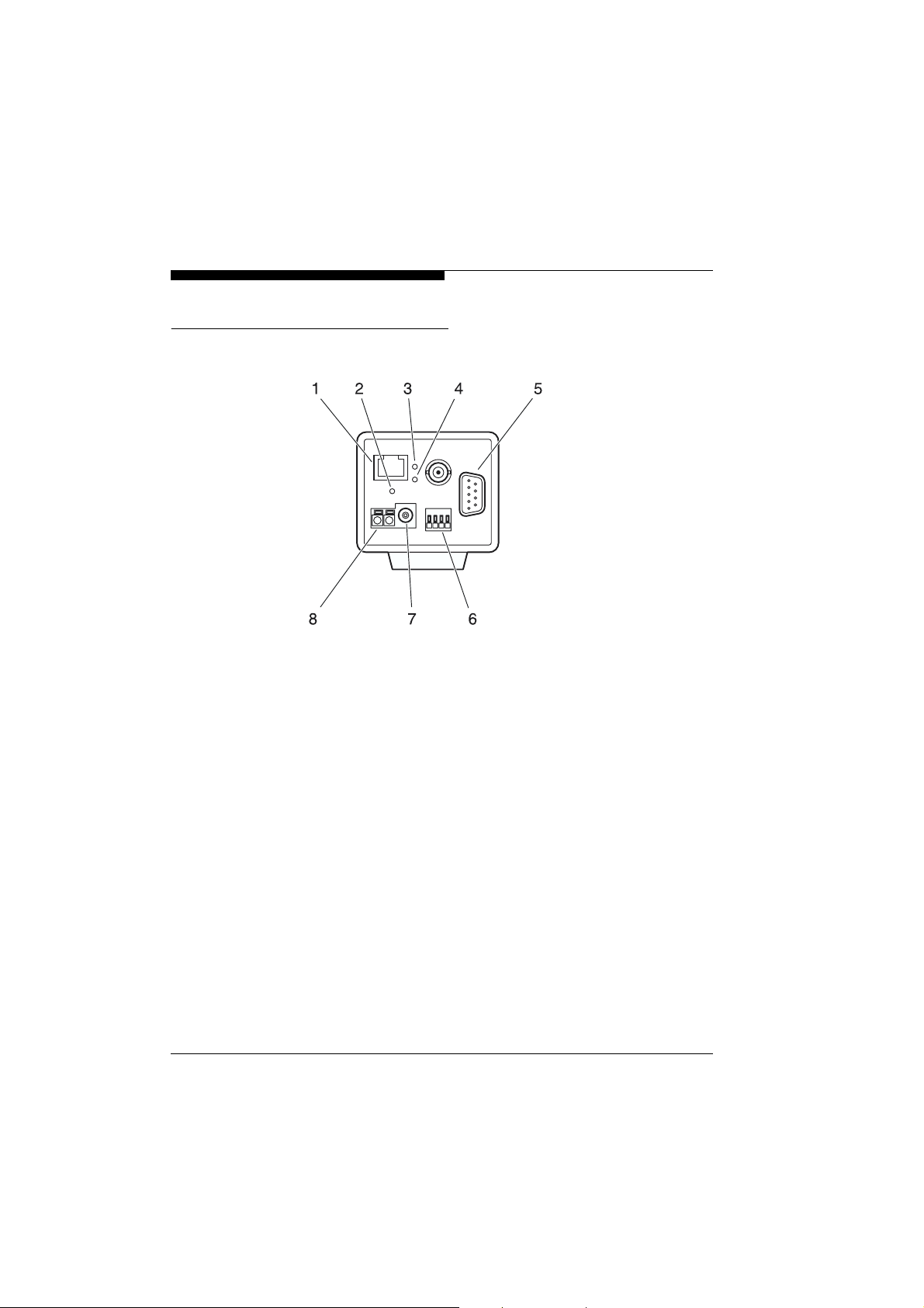
Connectors, controls and LEDs
Rear C 100
20
1
RJ45 jack
for connection with the network
2
LED
lights up green when ready
3
LED
flashes yellow when data packages are transmitted
4
LED
lights up green when the unit is connected to the network
5
Serial interface
9-pin sub-D connector (m) for transmission of control data and
for configuration with the terminal program
6
Plug-in terminals
alarm sensor input and relay output for switching of external
devices (e.g. lamps)
7
Jack
for connection of a power supply unit (instead of 8)
8
Plug-in terminals
for connection of a power supply unit (instead of 7)
10BASE-T
POWER
ACT
LINK
DC12V
COM RS232/422/485
ALARM
DC12V
VCS 100series
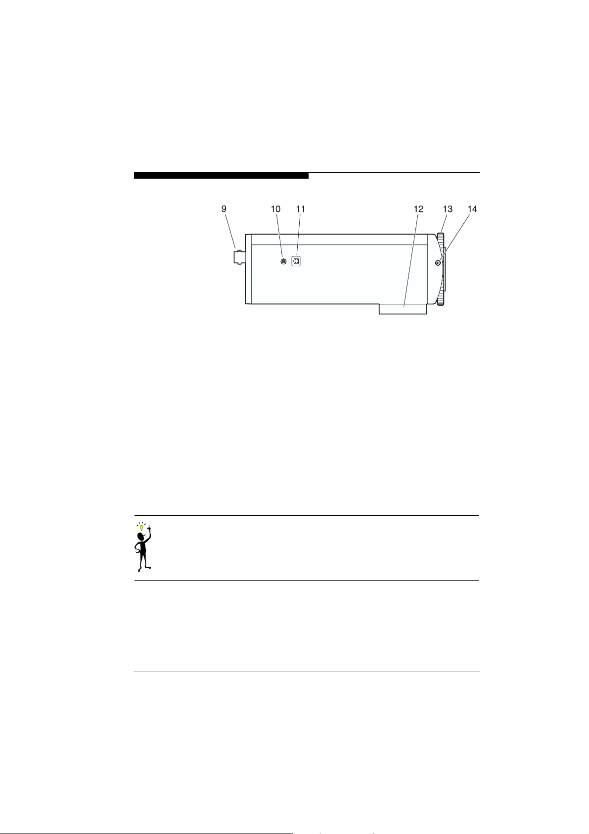
Side view C 100
Product description
9
BNC connector
MONITOR OUT
for connection of a monitor with coax cable
10
Potentiometer
for adjusting the voltage level of the iris control
11
4-pin standard jack
DC Iris
for connection of auto-iris lenses
12
Socket
for mounting the camera
13
Focus ring
for adjusting the back-focus
14
Securing screw
for locking the back-focus adjustment
Note
You will find further information on the LEDs on page 111.
VCS 100series
21
Product description
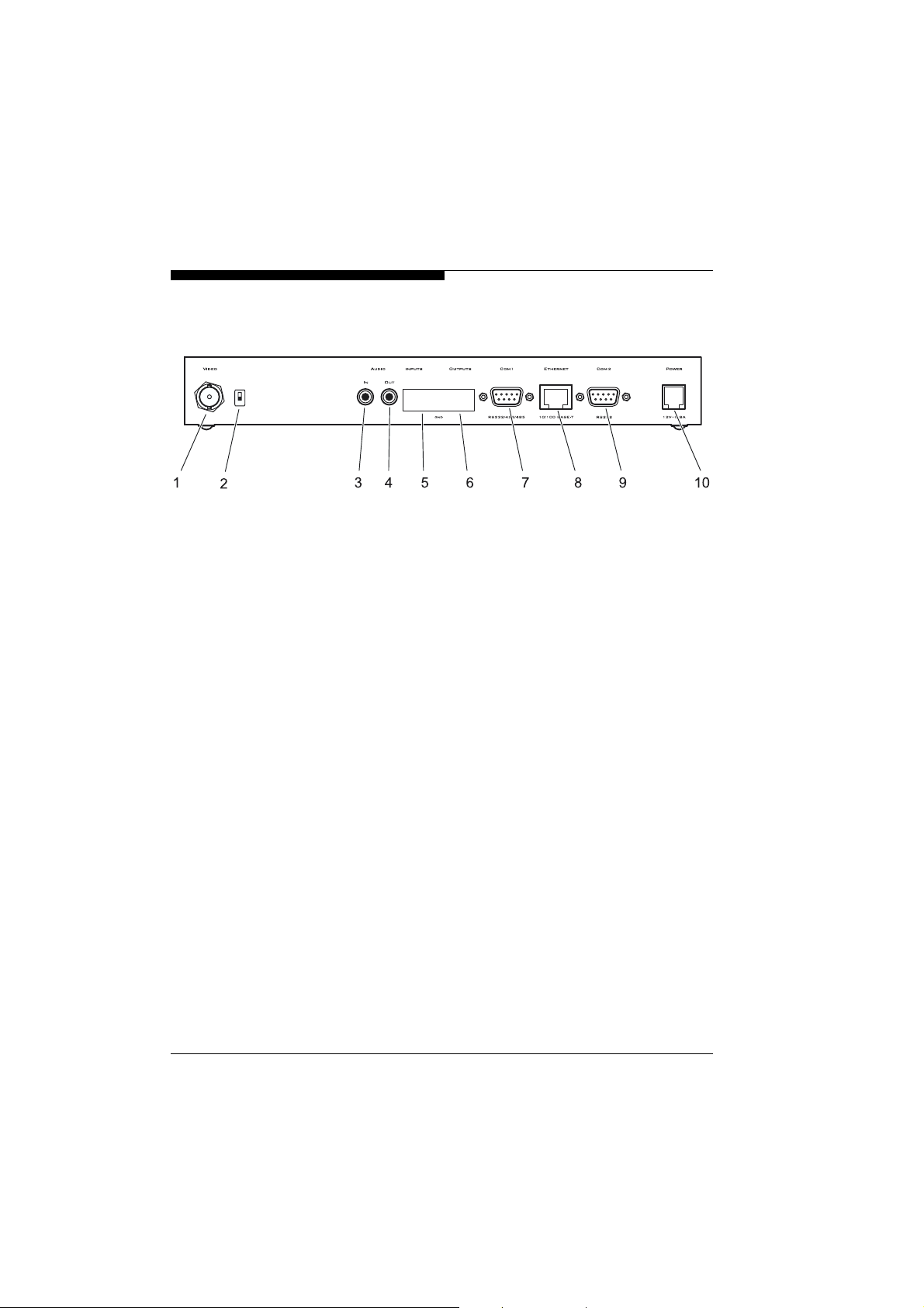
Rear VideoJet 100
T
1
Video input (transmitter)/Video output (receiver)
VIDEO
BNC connector for connection of the video source resp.
the monitor
2
DIP switch
T
for termination of the video input if the video signal is not
looped through
3
Audio input
AUDIO IN
3.5 mm mono jack bush for connection of the audio source
4
Audio output
AUDIO OUT
3.5 mm mono jack bush for connection of a loudspeaker
5
Screw clamp
INPUTS
for connection of alarm sensors or switches
6
Screw clamp
OUTPUTS
relay outputs for switching of external devices (e.g. lamps)
7
Serial interface
COM1
9-pin sub-D connector (m) for transmission of control data and
for configuration with the terminal program (RS232/422/485)
8
RJ45 jack
ETHERNET
for connection with the network
9
Serial interface
COM2
9-pin sub-D connector (m) for transmission of control data and
for configuration with the terminal program (RS232)
10
Jack
POWER
for connection of the plug-in power supply unit
22
VCS 100series
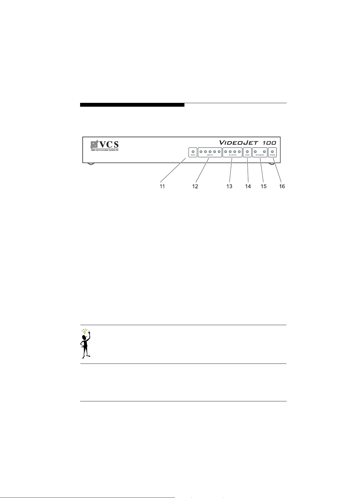
Front VideoJet 100
Product description
11
LED
VIDEO
lights up green when the input is active
12
LEDs
INPUTS
light up red with active alarm, light up green when ready
13
LEDs
OUTPUTS
light up green when the corresponding relay is switched
14
LED
COM
lights up yellow when data is transmitted over the serial
interfaces
15
LEDs
ETHERNET
green LED lights up when the unit is connected to the network
yellow LED flashes when data packages are transmitted
16
LED
POWER
lights up green when ready
Note
You will find further information on the LEDs on page 112.
VCS 100series
23
Product description
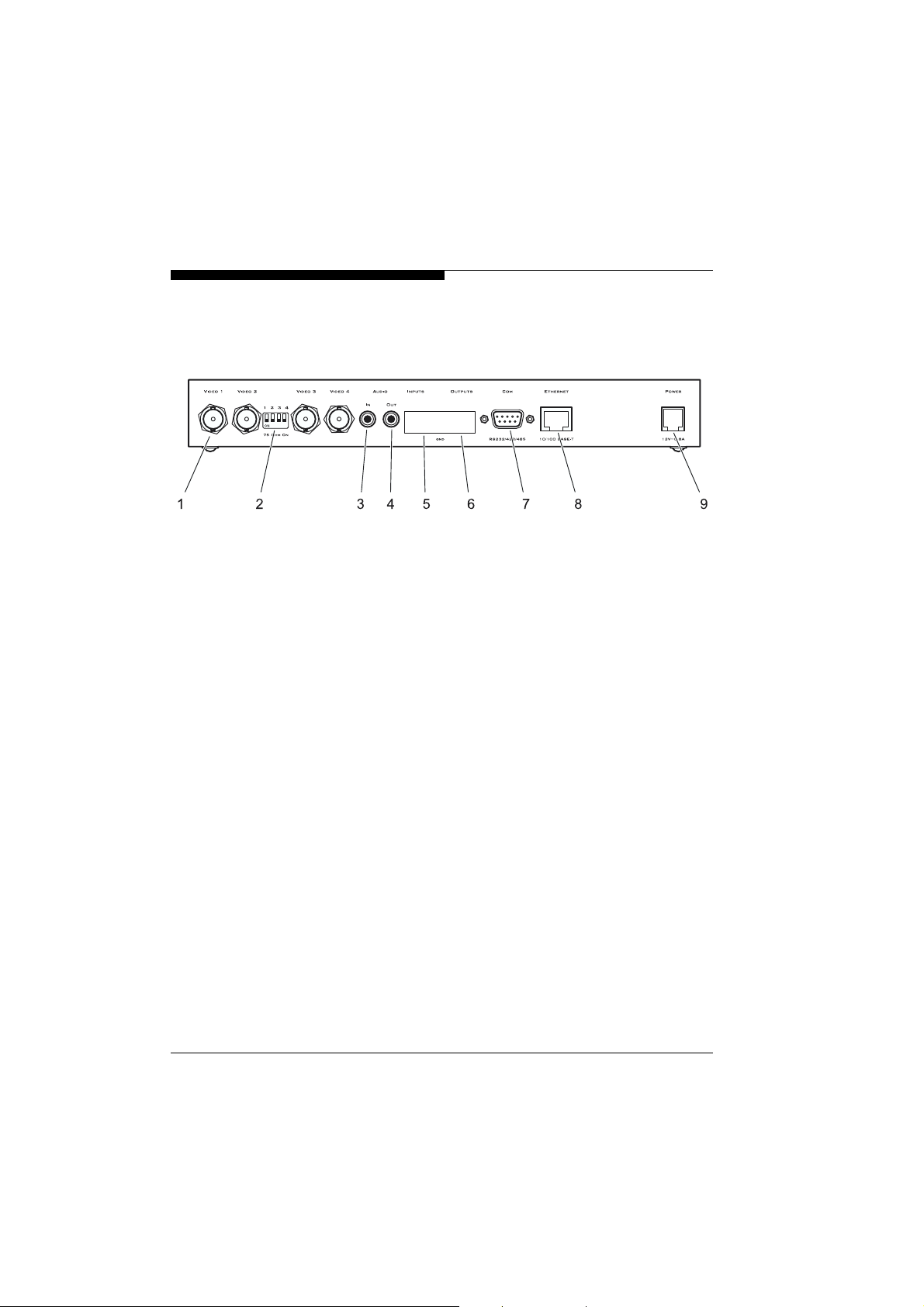
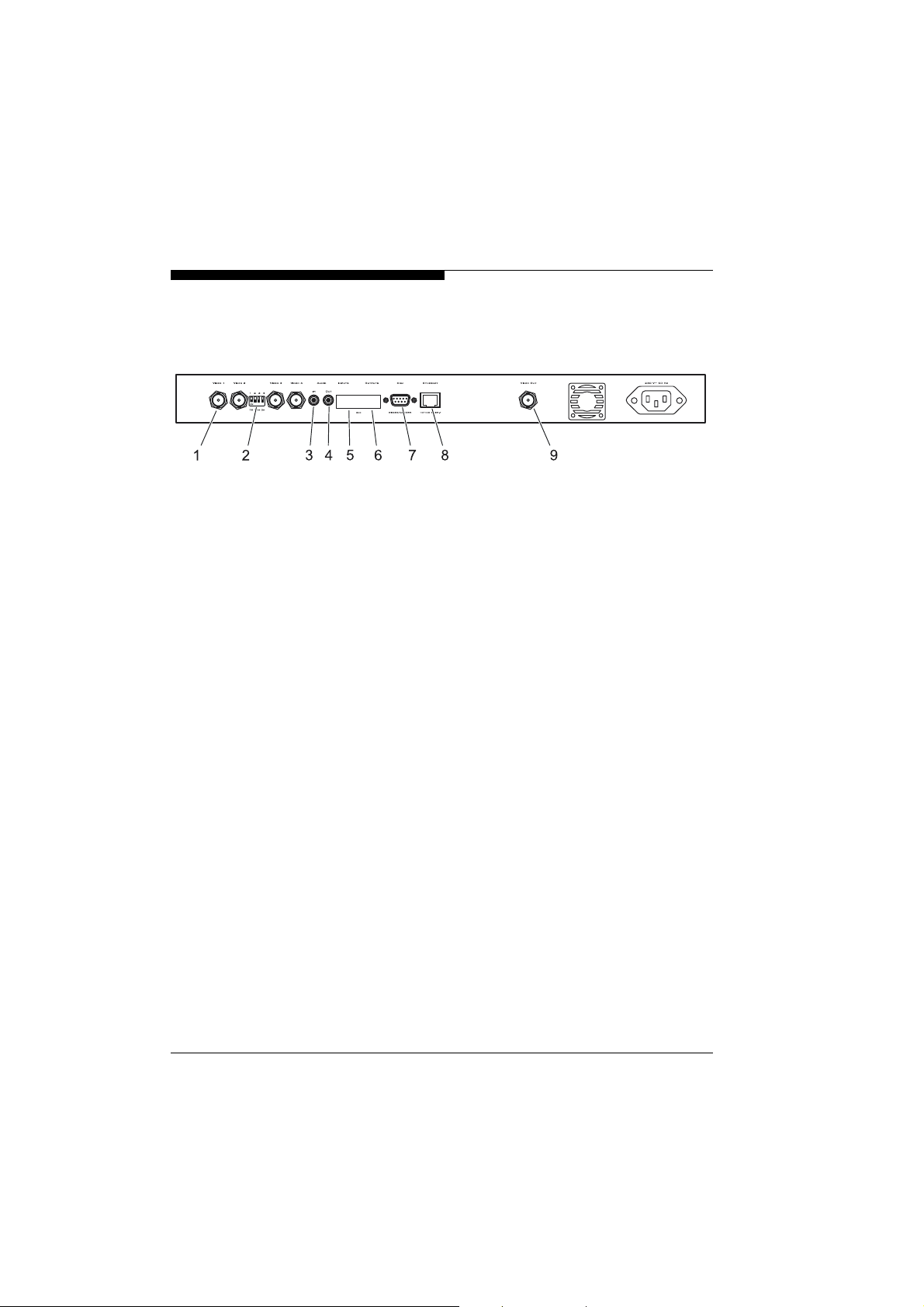
Rear VideoJet 400 (Desktop version)
1
Video inputs
BNC connectors for connection of the video sources
2
DIP switch
for termination of the corresponding video input if the video
signal is not looped through
3
Audio input
3.5 mm mono jack bush for connection of the audio source
4
Audio output
3.5 mm mono jack bush for connection of a loudspeaker
5
Screw clamp
for connection of alarm sensors or switches
6
Screw clamp
relay outputs for switching of external devices (e.g. lamps)
7
Serial interface
9-pin sub-D connector (m) for transmission of control data and
for configuration with the terminal program
8
RJ45 jack
for connection with the network
9
POWER
Jack
for connection of the plug-in power supply unit
VIDEO 1
75 OHM ON
AUDIO IN
AUDIO OUT
INPUTS
OUTPUTS
COM
ETHERNET
to
VIDEO 4
24
VCS 100series
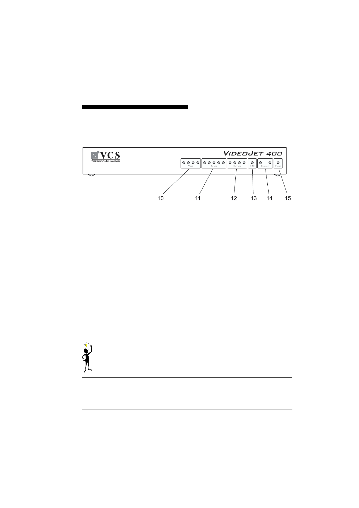
Front VideoJet 400 (Desktop version)
Product description
10
LEDs
VIDEO
light up green, when the corresponding input is active
11
LEDs
INPUTS
light up red with active alarm, light up green when ready
12
LEDs
OUTPUTS
light up green when the corresponding relay is switched
13
LED
COM
lights up yellow when data is transmitted over the serial
interface
14
LEDs
ETHERNET
green LED lights up when the unit is connected to the network
yellow LED flashes when data packages are transmitted
15
LED
POWER
lights up green when ready
Note
You will find further information on the LEDs on page 113.
VCS 100series
25
Product description
Rear VideoJet 400 (Cabinet version)
1
Video inputs
BNC connectors for connection of the video sources
2
DIP switch
for termination of the corresponding video input if the video
signal is not looped through
3
Audio input
3.5 mm mono jack bush for connection of the audio source
4
Audio output
3.5 mm mono jack bush for connection of a loudspeaker
5
Screw clamp
for connection of alarm sensors or switches
6
Screw clamp
relay outputs for switching of external devices (e.g. lamps)
7
Serial interface
9-pin sub-D connector (m) for transmission of control data and
for configuration with the terminal program
8
RJ45 jack
for connection with the network
9
Video output
BNC connector for connection of a monitor
VIDEO 1
75 OHM ON
AUDIO IN
AUDIO OUT
INPUTS
OUTPUTS
COM
ETHERNET
VIDEO OUT
to
VIDEO 4
26
VCS 100series
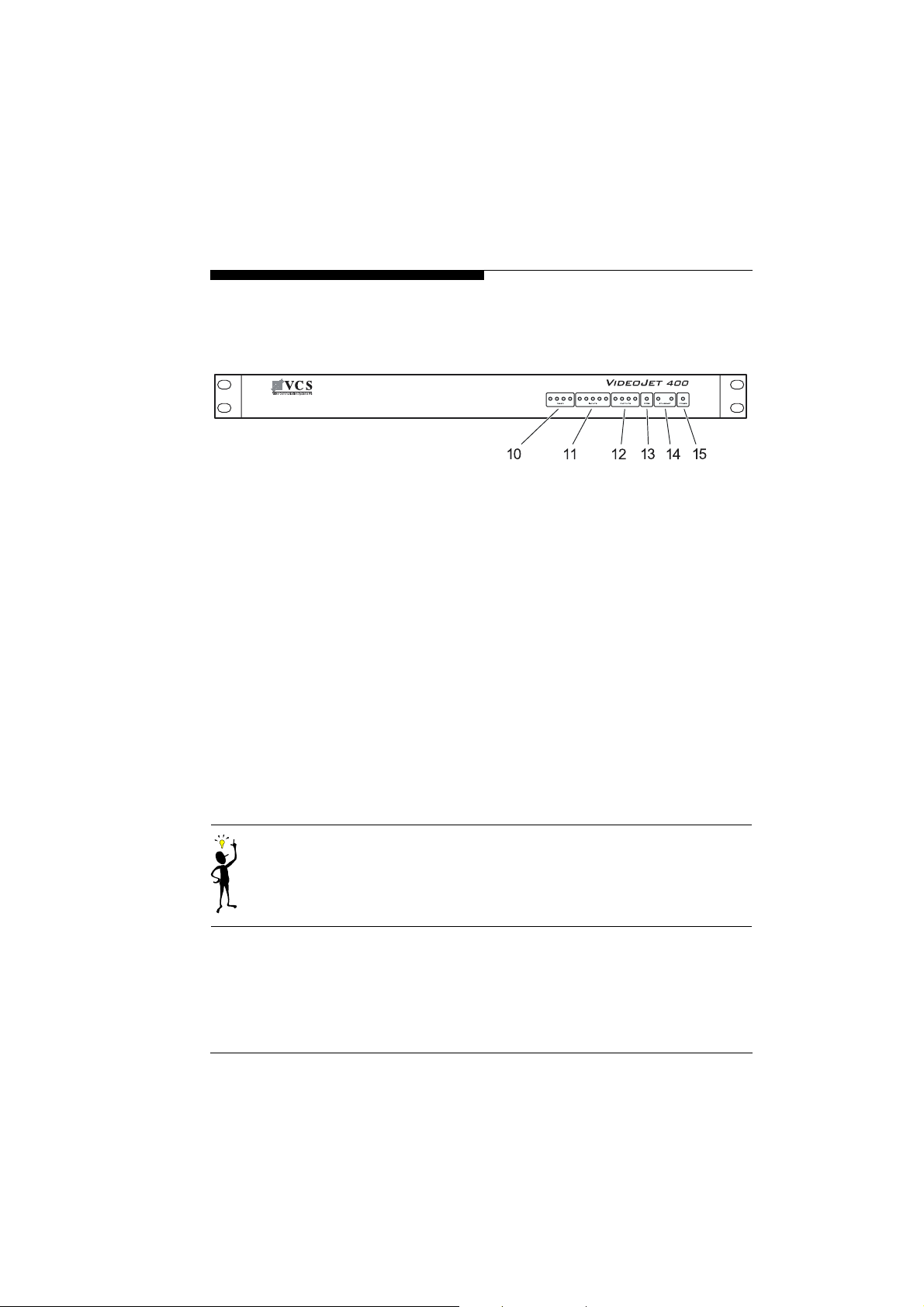
Front VideoJet 400 (Cabinet version)
Product description
10
LEDs
VIDEO
light up green, when the corresponding input is active
11
LEDs
INPUTS
light up red with active alarm, light up green when ready
12
LEDs
OUTPUTS
light up green when the corresponding relay is switched
13
LED
COM
lights up yellow when data is transmitted over the serial
interface
14
LEDs
ETHERNET
green LED lights up when the unit is connected to the network
yellow LED flashes when data packages are transmitted
15
LED
POWER
lights up green when ready
Note
You will find further information on the LEDs on page 113.
VCS 100series
27

Product description
28
VCS 100series
 Loading...