

VCS Videojet, Videojet ES, Videojet ESA, Videojet EE, Videojet EEA Series Manual

ideoJet
ideoJet
ideoJet
ideoJet
Manual

Copyright This manual is the intellectual property of VCS and is protected by
copyright. All rights are reserved. No part of this document may be
reproduced or transmitted for any purpose, by whatever means, be
they electronic or mechanical, without the express written permission of VCS.
Edition: November 2001
© Copyright 2001 VCS Video Communication Systems AG
Note This manual was compiled with the greatest of care and all informa-
tion double checked. At the time of printing the description was
complete and correct. Because of the further development of products, the content of the manual might change without prior notice.
VCS will not be liable for damage which is directly or indirectly due
to errors, incompleteness, or discrepancies between the manual
and the product described.
Trade marks All names used in this manual for hardware and software are very
probably registered trade marks and must be treated as such.

Contents
Chapter 1 Preface . . . . . . . . . . . . . . . . . . . . . . . . . . . . . . . . . . . . . . . . . . . . 7
Chapter 2 Safety information . . . . . . . . . . . . . . . . . . . . . . . . . . . . . . . . . . 11
Chapter 3 Product description . . . . . . . . . . . . . . . . . . . . . . . . . . . . . . . . 13
Conventions . . . . . . . . . . . . . . . . . . . . . . . . . . . . . . . . . . . . . . . . 7
Intended use . . . . . . . . . . . . . . . . . . . . . . . . . . . . . . . . . . . . . . . . 9
EU Guidelines . . . . . . . . . . . . . . . . . . . . . . . . . . . . . . . . . . . . . . . 9
Rating plate . . . . . . . . . . . . . . . . . . . . . . . . . . . . . . . . . . . . . . . . . 9
Electrical shock hazard . . . . . . . . . . . . . . . . . . . . . . . . . . . . . . . 11
Installation and operation . . . . . . . . . . . . . . . . . . . . . . . . . . . . . 11
Repairs and maintenance . . . . . . . . . . . . . . . . . . . . . . . . . . . . . 12
Scope of delivery . . . . . . . . . . . . . . . . . . . . . . . . . . . . . . . . . . . . 13
Preconditions for commissioning . . . . . . . . . . . . . . . . . . . . . . . 13
Preconditions for configuration . . . . . . . . . . . . . . . . . . . . . . . . . 13
Preconditions for operation . . . . . . . . . . . . . . . . . . . . . . . . . . . . 14
Overview of functions . . . . . . . . . . . . . . . . . . . . . . . . . . . . . . . . 14
Connections . . . . . . . . . . . . . . . . . . . . . . . . . . . . . . . . . . . . . . . 17
Chapter 4 Installation . . . . . . . . . . . . . . . . . . . . . . . . . . . . . . . . . . . . . . . . 19
VideoJet
Connections . . . . . . . . . . . . . . . . . . . . . . . . . . . . . . . . . . . . . . . 20
Switching on / Switching off . . . . . . . . . . . . . . . . . . . . . . . . . . . 23
Commissioning with terminal program . . . . . . . . . . . . . . . . . . . 24
1

Contents
Chapter 5 Configuration with web browser . . . . . . . . . . . . . . . . . . . . . . 27
Making the connection . . . . . . . . . . . . . . . . . . . . . . . . . . . . . . . 27
Navigation . . . . . . . . . . . . . . . . . . . . . . . . . . . . . . . . . . . . . . . . . 28
General procedure for configuration . . . . . . . . . . . . . . . . . . . . . 30
Identification . . . . . . . . . . . . . . . . . . . . . . . . . . . . . . . . . . . . . . . 31
Display settings . . . . . . . . . . . . . . . . . . . . . . . . . . . . . . . . . . . . . 33
Video settings . . . . . . . . . . . . . . . . . . . . . . . . . . . . . . . . . . . . . . 35
Audio settings . . . . . . . . . . . . . . . . . . . . . . . . . . . . . . . . . . . . . . 39
Alarm settings . . . . . . . . . . . . . . . . . . . . . . . . . . . . . . . . . . . . . . 41
Relay configuration . . . . . . . . . . . . . . . . . . . . . . . . . . . . . . . . . . 44
Interface settings . . . . . . . . . . . . . . . . . . . . . . . . . . . . . . . . . . . . 46
Service settings . . . . . . . . . . . . . . . . . . . . . . . . . . . . . . . . . . . . . 48
Function test . . . . . . . . . . . . . . . . . . . . . . . . . . . . . . . . . . . . . . . 53
Chapter 6 Operation . . . . . . . . . . . . . . . . . . . . . . . . . . . . . . . . . . . . . . . . . 55
Operation with the Microsoft Internet Explorer . . . . . . . . . . . . . 55
Hardware connection between
VideoJet
devices . . . . . . . . . 59
Operation with software decoder . . . . . . . . . . . . . . . . . . . . . . . . 60
Chapter 7 Care and Service . . . . . . . . . . . . . . . . . . . . . . . . . . . . . . . . . . . 61
Checking the network . . . . . . . . . . . . . . . . . . . . . . . . . . . . . . . . 61
Maintenance . . . . . . . . . . . . . . . . . . . . . . . . . . . . . . . . . . . . . . . 61
Further sale, disposal . . . . . . . . . . . . . . . . . . . . . . . . . . . . . . . . 62
Chapter 8 Annex . . . . . . . . . . . . . . . . . . . . . . . . . . . . . . . . . . . . . . . . . . . . 63
Faults – possible causes and remedy . . . . . . . . . . . . . . . . . . . . 63
LEDs . . . . . . . . . . . . . . . . . . . . . . . . . . . . . . . . . . . . . . . . . . . . . 65
Glossary . . . . . . . . . . . . . . . . . . . . . . . . . . . . . . . . . . . . . . . . . . 66
Application examples . . . . . . . . . . . . . . . . . . . . . . . . . . . . . . . . 69
Specifications . . . . . . . . . . . . . . . . . . . . . . . . . . . . . . . . . . . . . . 71
Index . . . . . . . . . . . . . . . . . . . . . . . . . . . . . . . . . . . . . . . . . . . . . 73
2
VideoJet
Preface
Conventions
1
These Installation and Operating Instructions are intended for persons authorised to install and operate the
national and any relevant regional regulations relating to electronics must be observed at all times. The Operating Instructions
explain the installation and operation of the
In this manual, the following symbols and notations are used to
draw attention to special situations:
Hazard! or Attention!
This symbol indicates that failure to follow the safety instructions
given may directly endanger people, cause damage to the system
or to other equipment. The symbol represents a direct threat of danger.
VideoJet
VideoJet
. International,
.
VideoJet
Note
This symbol indicates tips and notes that make using the device
easier and more convenient.
Note
This symbol indicates that you might have to find out special information to be able to make the settings or start up the system correctly.
7

Preface
The following typographic conventions are used in this manual::
Configuration Menu names and window and key names and
parameters
[Enter], [C] Key names
[Ctrl] + [C] Two or more keys that are pressed simul-
taneously.
ping Command line input and output
8
VideoJet

Intended use
Preface
EU Guidelines
Rating plate
The Network Video Server
audio and control signals via data networks (Ethernet LAN). It is
designed for use in CCTV systems. The connection of an external
alarm generator allows various functions to be triggered automatically. Other applications are not permitted.
In the event of questions concerning the use of the server which are
not answered in this manual, please contact:
VCS Video Communication Systems AG
Forchheimer Straße 4
D – 90425 Nürnberg
Phone +49 (0) 911 93 45 6-0
Fax +49 (0) 911 93 45 6-66
Support@vcs.com
The Network Video Server
tions of European Guidelines 89/336 (Electromagnetic Compatibility) and 73/23, amended by 93/68 (Low-Voltage Guideline).
VideoJet
VideoJet
serves to transmit video,
complies with the specifica-
VideoJet
For exact identification, you will find the model designation and
serial number on the rating plate on the bottom of the housing.
Please note this information here before installation in order to have
it to hand in the event of queries or spare parts orders.
9

Preface
10
VideoJet

Safety information
Electrical shock hazard
z Never attempt to connect the unit to any power network other
than the one for which it was intended.
z Use only the mains lead supplied.
z Do not open the housing of the power supply unit.
z Disconnect the power supply unit from the mains power supply
and from all other devices if a fault occurs.
z Install the power supply unit and server only in a dry place pro-
tected against the elements.
z If you are uncertain about the safe operation of the unit, shut it
down immediately and secure it to prevent any unauthorised
start-up. Safe operation is no longer possible, for example,
– if damage is visible to the server of the cables,
– if the server no longer operates correctly,
– if the server has been exposed to rain or moisture,
– if objects have penetrated inside the server,
– after long storage under improper conditions or
– after heavy demands during transport.
Have the system checked by VCS in such cases.
2
Installation and operation
z All applicable electrical codes and regulations must be observed
and followed at all times during the installation.
VideoJet
11

Safety information
z Before installing or operating the system, ensure that you have
read and understood the documentation for other equipment
connected to the unit, e.g. cameras. These contain important
safety notices and information concerning permissible applications.
z Perform only the installation and operating work described in this
manual. All other work beyond this may lead to injuries to persons and damage to the system or other equipment.
Repairs and maintenance
z Never open the housing of the
VideoJet
. The unit contains no
parts which you can repair or replace.
z Never open the housing of the power supply unit. The power
supply unit contains no parts which you can repair or replace.
z Ensure that only qualified, specialist personnel (electrical techni-
cians) are permitted to carry out maintenance or repair work.
12
VideoJet

Product description
Scope of delivery
3
z
VideoJet
VideoJet
VideoJet
VideoJet
each incl. plug-in power pack
z Manual german/english
z Software
es
transmitter, or
esa
transmitter with audio option, or
ee
receiver, or
eea
receiver with audio option
PROVILite
Preconditions for commissioning
z Computer with operating system Windows 95/98/NT and a gate-
way to the network
z Microsoft Internet Explorer web browser (from Version 5) or free
serial interface and terminal program
Preconditions for configuration
z Computer with operating system Windows 95/98/NT and a gate-
way to the network
z Microsoft Internet Explorer web browser (from Version 5) or VCS
software decoder e.g.
from VCS
PROVILite
VideoJet
13

Product description
Preconditions for operation
z Computer with operating system Windows 95/98/NT and a gate-
way to the network
z Microsoft Internet Explorer web browser (from Version 5) or VCS
software decoder e.g.
or
z Receiver
VideoJet
Overview of functions
PROVILook
ee
or
VideoJet
eea
and video monitor
Network video
server
The
VideoJet
is a network video server. It serves primarily for
encoding and decoding video, audio and control data for transfer
via an Ethernet LAN. By using existing networks, the
permits the simple installation and configuration of CCTV systems.
VideoJet
Two
receiver
devices, the transmitter
VideoJet
transfer without PC. The system can be extended to include further
receivers so that video sequences from one transmitter can be
received by several receivers simultaneously.
Receiver The corresponding
decoding software, for example
installed Microsoft Internet Explorer can always be used as receivers.
Multicast function The
VideoJet
supports the standard H.323 and is thus compatible with many video-conferencing systems. Thanks to efficient
encoding, the data transmission rate remains low, even with maximum image quality and 30 images/s; furthermore, it can be adapted
over a wide range to meet the local requirements.
VideoJet
ee
, can form a stand-alone System for data
VideoJet
devices or computers with installed
PROVIDo
VideoJet
from VCS, or with
es
and the
14
VideoJet

Product description
In appropriately configured networks, the multicast function permits
the simultaneous video transmission in real time to several receivers. A precondition for multicast mode is a multicast-compatible
network using the UDP protocol and the IGMP protocol. Other
group management protocols are not supported.
Remote control For remote control of external equipment, e.g. pan-and-tilt heads
for cameras or motorised zoom lenses, the control data are transmitted via the bidirectional serial interface of the
VideoJet
. This
interface can also be used for the transmission of transparent data.
Configuration The
VideoJet
can be configured with a browser via the local net-
work (intranet) or via the internet.
Firmware updates and the quick uploading of device configurations
are possible in the same way.
Audio option In addition to the basic units,
devices
VideoJet
esa
and
these servers it is possible to also transmit audio data (e.g. from an
intercom system) in addition to video transmission. The server
transmits audio data bidirectionally and parallel to the video data.
VideoJet
VideoJet
es
and
eea
VideoJet
are also available. With
ee
, the
VideoJet
15

Product description
Summary The
z Video, audio and data transmission via data networks.
z Multicast function for simultaneous image transmission to
z Colour image resolution (704 × 576 pixels) with up to
z Video transmission compatible with international standards
z Integral Ethernet interface (10 Base-T)
z Transparent bidirectional data channel
z Remote control of all internal functions via UDP/IP
z Password protection to prevent unauthorised access
z Switching input for external sensors (e.g. door contacts)
z Switching output for switching external devices (e.g. lights or
z Event-controlled automatic connection setup (e.g. when
z Integral video sensor for motion alarms
z Video signal monitoring
z Automatic transmission of alarm e-mails with attached image
z Video ring memory for recording of alarm pre-histories
z Quick and convenient configuration via web browser
z Firmware update via flash memory
VideoJet
offers the following main functions:
several receivers
30 images/s
H.323, H.261 and M-JPEG
sirens)
switching on and at alarms)
16
VideoJet
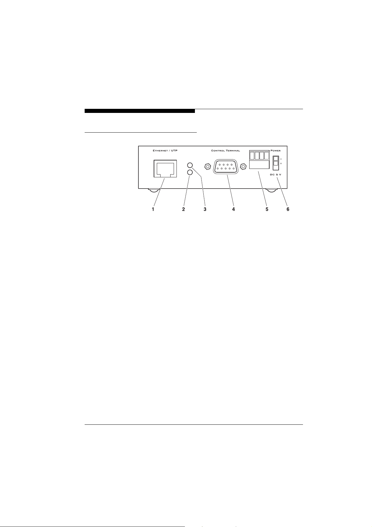
Connections
Product description
1 RJ45 jack ETHERNET/UTP
for connection with the network
2 LED
lights up green when the unit is connected to the network
3 LED
flashes yellow when data packages are transmitted
4 Serial interface CONTROL TERMINAL
9-pin sub-D connector (m) for the configuration with a terminal
program
5 Screw clamp ALARM I/O
signal input and relay output
6 Jack POWER
for connection of the plug-in power supply unit
VideoJet
17
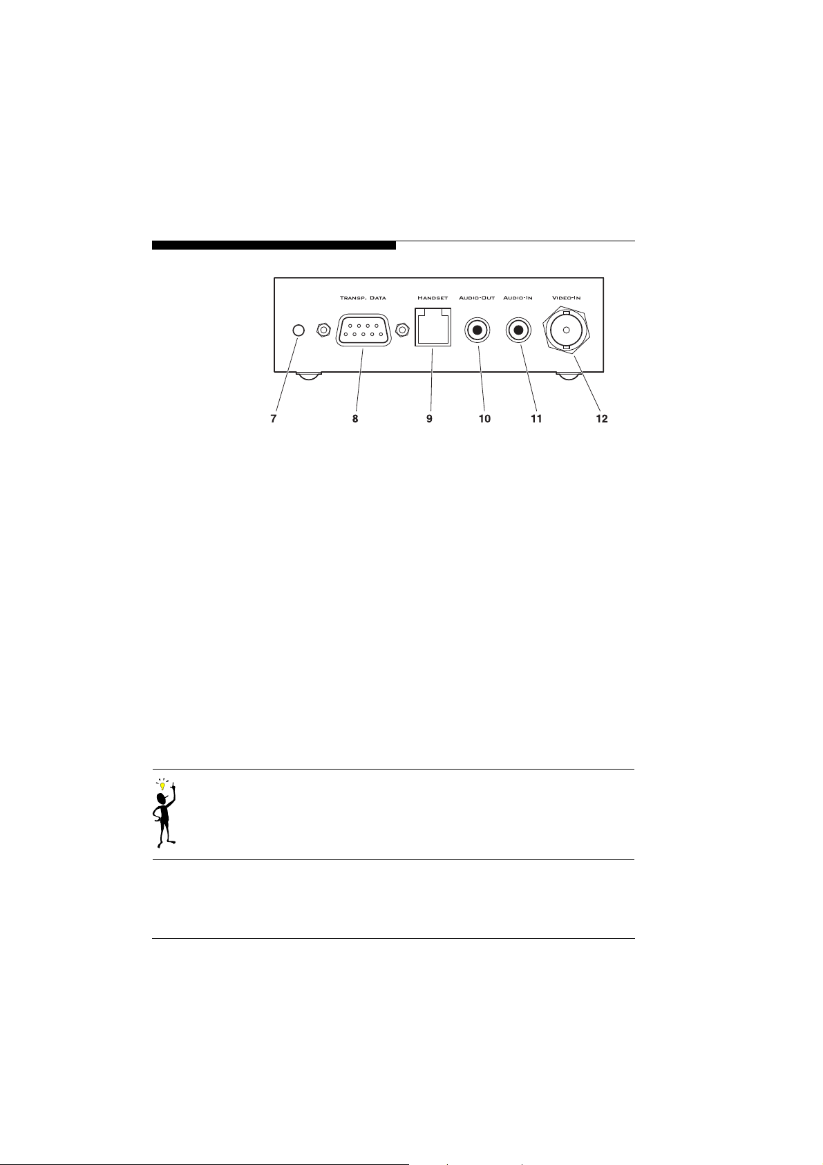
Product description
7 LED
lights up green when ready
8 Serial interface TRANSP. DATA
9-pin sub-D connector (m) for transmission of control data
9 RJ11 jack HANDSET
for connection of a telephone handset
(only
VideoJet
esa
and
VideoJet
eea
)
10 Cinch jack AUDIO OUT
for connection of a loudspeaker
(only
VideoJet
esa
and
VideoJet
eea
)
11 Cinch jack AUDIO IN
for connection of a microphone
(only
VideoJet
12 BNC connector VIDEO-IN or VIDEO-OUT
Camera interface (
or monitor interface (
esa
and
VideoJet
VideoJet
VideoJet
es
)
ee
eea
)
)
18
Note
You will find further informations on the LEDs on page 65.
VideoJet
Installation
4
Thanks to its compact design, the
installation in very confined spaces, such as in cable trenches or
camera housings.
Attention!
The unit is designed for operation indoors. Choose a site for installation which ensures that the server is exposed to neither extreme
temperatures nor extreme moisture or humidity. The ambient temperature must lie between +5 and +40 °C, the relative humidity
must not exceed 80%.
During operation, the server generates a great deal of heat. Therefore ensure sufficient ventilation and an adequate distance to heatsensitive equipment or objects.
Please observe the following installation conditions:
z Do not install the
tors or other sources of heat. Avoid installing the
where it is exposed to direct sunlight.
z Ensure sufficient space for laying the cables.
z Ensure adequate ventilation of the
z For all cable connections, use only the supplied or suitable
cables which also prevent any electrical interference, where
necessary.
z Lay and install all cables in such a way that they cannot be
damaged and ensure sufficient strain relief.
VideoJet
VideoJet
in the immediate vicinity of radia-
VideoJet
is ideally suited for
VideoJet
.
VideoJet
19

Installation
Connections
Camera/monitor Depending on the device model used, you can connect a
VideoJet
ee
and
has a relay output for switching external devices,
Network
connection
Alarm inputs,
peripheral
equipment
video source (
(
VideoJet
video sources generating a standard PAL or NTSC signal and all
monitors suitable for standard PAL or NTSC video signals can be
used for this purpose.
Connect a camera or other video source to the BNC jack VIDEO-IN
)
of the transmitter using a video cable (75 Ohm, BNC connector),
or
Connect a monitor to the BNC jack VIDEO-OUT of the receiver
)
using a video cable (75 Ohm, BNC connector).
You can connect the
10/100 BASE-T network. Use a standard cable UTP Category 5
with RJ45 connectors for this connection.
Connect the network cable to the ETHERNET/UTP jack.
)
The alarm input of the
generators, e.g. door contacts or sensors. With appropriate configuration, an alarm generator can, for example, trigger the automatic
connection set-up between the
You can connect switches or NO contacts directly without a separate power supply.
The
VideoJet
e.g. lights or alarm sirens. This control output can be used interactively during an active connection with the
with appropriate configuration, the control output can activate, for
example, an alarm siren in response to an alarm signal.
Pull terminal block from its plug-in base.
)
es
and
VideoJet
VideoJet
VideoJet
VideoJet
eea
) to the IPCom. All cameras and
either directly or via a hub to a
serves to connect external alarm
VideoJet
esa
) or a monitor
and the remote station.
VideoJet
. Furthermore
20
VideoJet
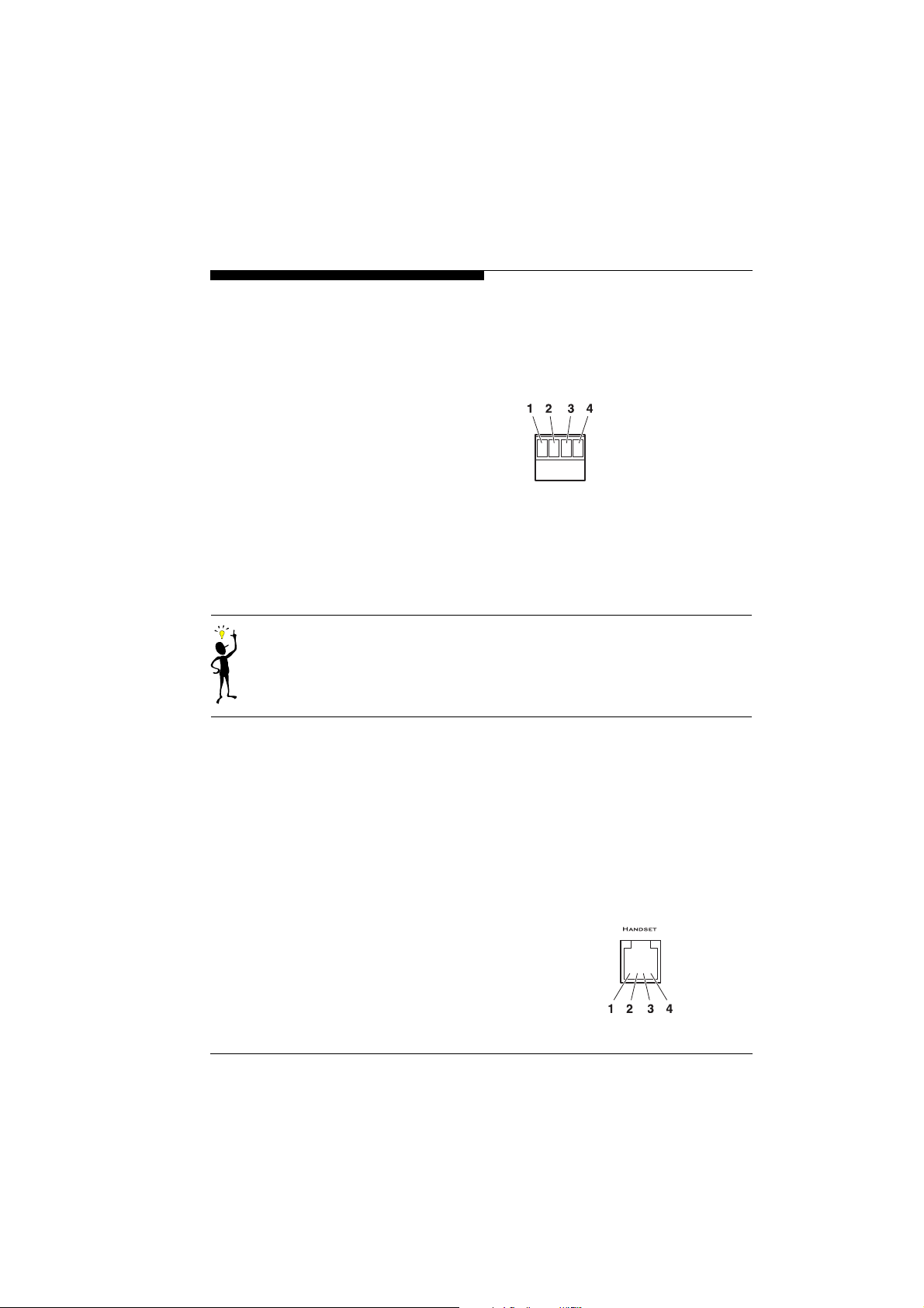
Lay the conductors to the terminals and then check that all screws
)
are securely tightened.
Push the terminal block onto the plug-in base again.
)
1 Alarm input +
2 Alarm input ground
3 Control output
4 Control output
Installation
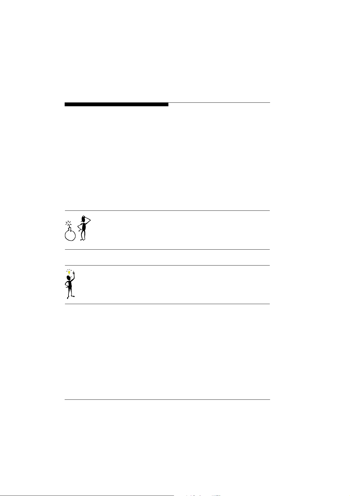
Audio connection The
HANDSET and AUDIO-IN or AUDIO-OUT. You can use the corresponding interfaces only alternatively, not simultaneously.
Note
The audio function is only available on the devices
and
The audio signals are transmitted bidirectionally and simultaneously with the video signals. This allows, for example, a loudspeaker or door intercom system at the surveillance location to be
controlled.
Connect the telephone handset to the RJ11 jack HANDSET,
)
or
Connect the microphone and loudspeaker to the cinch jacks
)
AUDIO-IN and AUDIO-OUT.
1 Handset microphone +
2 Handset speaker +
3 Handset speaker –
4 Handset microphone ground
VideoJet
VideoJet
provides two audio channels with the designations
eea
. It cannot be retrofitted on the other models.
VideoJet
esa
VideoJet
21
Installation
Data terminal You can connect a data terminal to the
ing and local control. The data terminal consists of a computer with
a terminal program. Use a standard serial cable for the connection.
Connect the RS232 interface CONTROL TERMINAL to a free serial
)
interface of the computer.
Camera and
device control
The connection TRANSP. DATA serves to control a device connected to the
The range of devices with can be controlled with
dome camera systems) is being constantly expanded. Information
on installation and device control can be obtained from the supplier
of the controlled device.
Attention!
When installing and operating the device to be controlled, observe
the corresponding documentation. It contains important safety
notes and information on permissible applications.
Note
The transmission of transparent data is only possible when a video
connection has been made.
VideoJet
, e.g. camera, multiplexer or VCR.
VideoJet
for commission-
VideoJet
(e.g.
22
VideoJet
Switching on / Switching off
Installation
Mains connection The scope of supply of the
pack.
Attention!
Use only the plug-in power supply unit supplied for operation of the
VideoJet
equipment to prevent surge voltages, interference voltage peaks or
power failures in the mains supply from reaching the server.
Connect the
the other connections have been made.
The
nected the plug-in power supply unit to the
the plug of the plug-in power supply unit into a plug socket, the
server is ready for operation.
Push the plug of the power supply unit cable into the jack POWER
)
until it latches.
Plug the plug-in power supply unit into a fused mains power plug
)
socket. The green LED on the front of the
the server is ready for operation.
When the network connection has been correctly made, the green
LED on the rear side also lights up. The flashing yellow LED signals
the transport of data packages via the network.
. Take appropriate measures or install the appropriate
VideoJet
VideoJet
has no mains power switch. When you have con-
to the mains power supply only when all
VideoJet
includes a plug-in power
VideoJet
VideoJet
and inserted
lights up and
VideoJet
23
Installation
Commissioning
with terminal program
Data terminal You can connect a data terminal to the
unit into operation and for the local control. The data terminal consists of a computer with a terminal program. For the connection use
a serial standard cable.
You can use e.g. the Windows application HyperTerminal as terminal program.
Note
Information on the installation and use of HyperTerminal can be
found in the documentation or in the online Help for Windows.
)
)
Configuring the
terminal program
First, disconnect the
Connect the sub-D jack CONTROL TERMINAL of the
to a free serial port of the computer.
The transmission parameters have to match for communication
between terminal program and
for the terminal program:
z 19,200 bits/s
z 8 data bits
z No parity check
z 1 stop bit
z Protocol Xon/Xoff
VideoJet
from the network.
VideoJet
VideoJet
for putting the
VideoJet
. Set the following values
24
VideoJet
Installation
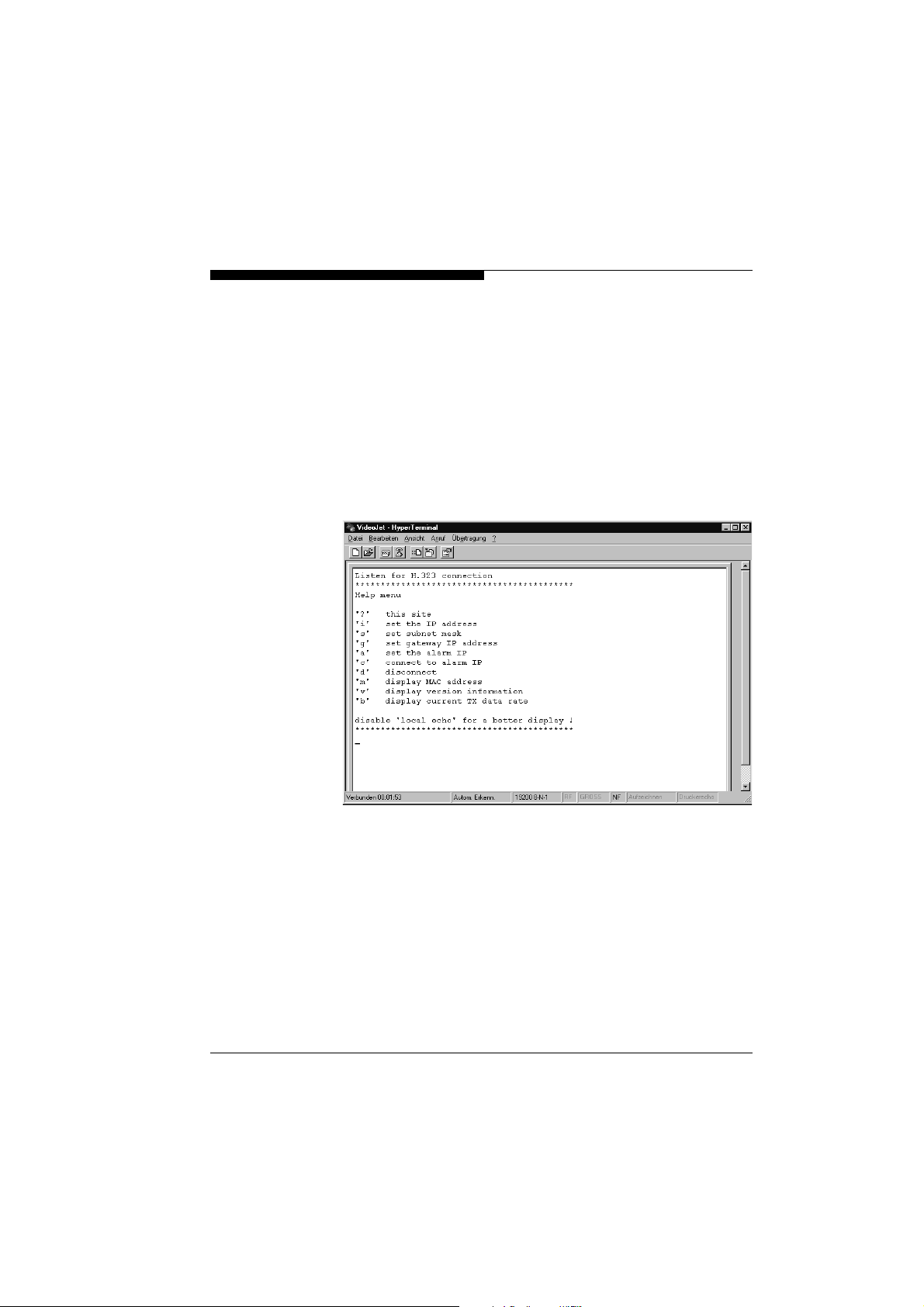
Command inputs After the connection has been made, the
transmits the Help page.
z If necessary, switch off the local echo so that input values are not
repeated.
z Enter only one command at a time and do not terminate this
input by pressing the [ENTER] key.
z After entering a value (e.g. an IP address), check the entered
characters again and only then press the [ENTER] key to transmit the values to the
VideoJet
.
VideoJet
automatically
VideoJet
25

Installation
Assigning the
IP address
Further
parameters
In order for the
be assigned a valid IP address for your network.
The following addresses have been preset at the factory:
VideoJet
VideoJet
Start a terminal program, e.g. HyperTerminal.
)
Enter i. The existing IP address is displayed and you are prompted
)
to enter a new IP address.
Enter the new IP address and press the [ENTER] key. The new IP
)
address is displayed and is immediately valid.
Using the terminal program, you can check and, if necessary,
change further fundamental parameters.
For this, you can use the following commands:
Displays the 'Help' page
?
Displays the current IP address and prompts the user to enter a
i
new IP address
Displays the current subnet mask address and prompts the user
s
to enter a new address
Displays the current gateway address and prompts the user to
g
enter a new address
Displays the current alarm IP address and prompts the user to
a
enter a new address
Sets up a connection to the alarm IP address
c
Terminates the current connection
d
Displays the MAC address of the
m
Displays the hardware and software version of the
v
Displays the current data rate
b
VideoJet
es
and
ee
and
to be operated in your network, it has to
VideoJet
VideoJet
esa
: 192.168.0.1
eea
: 192.168.0.2
VideoJet
VideoJet
26
VideoJet
 Loading...