

Page 1

[在此处键入]
User Manual
EIS-6500A00 Embedded Server
Page 2

Shenzhen Vcode Data Equipment Co., Ltd.
Shenzhen Vcode Data Equipment Co., Ltd.
Content
i
We Vcode provide full support to customers, contact us freely if any questions.
Shenzhen Vcode Data Equipment Co., Ltd.
Address
Room 601,Block A,Unis Infor habor,Langshan Rd.,Hi-Tech Industrial Park(North),Nanshan
District,Shenzhen,PRC
Website
http://www.szvcode.com
Technical Support
+86-0755-33379860
Fax number
+86-0755-33379861
Postalcode
518057
Copyright © Shenzhen Vcode Data Equipment Co., Ltd. 2012. All rights reserved.
All information in this user manual is protected by copyright law. Whereby, no organization or individual shall copy
or reproduce the whole or part of this user manual by any means without written authorization from Shenzhen
Vcode Data Equipment Co., Ltd..
Trademarks and Permissions
are the trademarks and logos of Shenzhen Vcode Data Equipment Co., Ltd.. Other trademarks and
logos mentioned in this manual belong to other organizations related. Shenzhen Vcode Data Equipment Co., Ltd.
does not own the rights of other trademarks and logos.
Caution
Due to product updates or functional upgrading, we may renew the content of this file, and this file only for
reference. All statement, information, suggestion etc. in this file do not compose any form of guarantee and
Vcode reserves the right of final explanation.
Page 3
Shenzhen Vcode Data Equipment Co., Ltd.
ii
(2012-09-14)
Purpose
Model
Version
EIS6500
A00
Chapter
Description
1
Features of EIS6500 Embedded Server and target market.
2
SW & HW structure of EIS6500 Embedded Server.
3
How to installation of EIS6500 Embedded Server.
4
Prepare to configure EIS6500 Embedded Server.
5
How to configure EIS6500 Embedded Server.
6
Typical application of EIS6500 Embedded Server.
7
Frequently asked questions.
About This Document
EIS6500 Embedded Server is designed and manufactured by Shenzhen VCODE Data
Equipment Co., Ltd., it based on Low power consumption computer technology, industrial
class quality. With its embedded LAN and Wi-Fi module, it widely used in multiple case like
local wired connection, local wireless security connection, etc. This document introduced
how to use EIS6500 and its function features.
Related Versions
The following table lists the product versions related to this document.
Organization
Page 4
Shenzhen Vcode Data Equipment Co., Ltd.
Shenzhen Vcode Data Equipment Co., Ltd.
Content
iii
Conventions
Symbol
Description
Indicates a potentially hazardous situation, which if not avoided,
could result in equipment damage, data loss, performance
degradation, or unexpected results.
Indicates a tip that may help you address a problem or save your
time.
Provides additional information to emphasize or supplement
important points of the main text.
Convention
Description
Boldface
The keywords of a command line are in boldface.
Italic
Command arguments are in italics.
[ ]
Items (keywords or arguments) in brackets [ ] are optional.
{ x | y | ... }
Optional items are grouped in braces and separated by vertical ars.
One item is selected.
[ x | y | ... ]
Optional items are grouped in brackets and separated by vertical
bars. One item is selected or no item is selected.
{ x | y | ... } *
Optional items are grouped in braces and separated by vertical ars.
A minimum of one item or a maximum of all items can be selected.
[ x | y | ... ] *
Optional items are grouped in brackets and separated by vertical
ars. Several items or no item can be selected.
&<1-n>
The parameter before the & sign can be repeated 1 to n times.
#
A line starting with the # sign is comments.
Symbol Conventions
The symbols that may be found in this document are defined as follows.
Command Conventions
Page 5

Shenzhen Vcode Data Equipment Co., Ltd.
iv
(2012-09-14)
GUI Conventions
Convention
Description
Boldface
Buttons, menus, parameters, tabs, window, and dialog titles are
in boldface. For example, click OK.
>
Multi-level menus are in boldface and separated by the ">" signs.
For example, choose File > Create > Folder.
Format
Description
Key
Press the key. For example, press Enter and press Tab.
Key 1+Key 2
Press the keys concurrently. For example, pressing Ctrl+Alt+A means
the three keys should be pressed concurrently.
Key 1, Key 2
Press the keys in turn. For example, pressing Alt, A means the two
keys should be pressed in turn.
Action
Description
Click
Select and release the primary mouse button without moving the
pointer.
Double-click
Press the primary mouse button twice continuously and quickly
without moving the pointer.
Drag
Press and hold the primary mouse button and move the pointer to a
certain position.
Keyboard Operations
Mouse Operation
Page 6

Shenzhen Vcode Data Equipment Co., Ltd.
Shenzhen Vcode Data Equipment Co., Ltd.
Content
v
Content
1 Product Introduce ............................................................................................................................. 1
1.1 Overview .......................................................................................................................................................... 1
1.2 Product positioning .......................................................................................................................................... 1
1.3 Function & Features ......................................................................................................................................... 2
1.4 Specification ................................................................................................ ..................................................... 2
1.5 FCC Statement .................................................................................................................................................. 3
2 Product structure .............................................................................................................................. 4
2.1 Hardware .......................................................................................................................................................... 4
2.1.1 Appearance & Size .................................................................................................................................. 4
2.1.2 Accessories .............................................................................................................................................. 7
2.2 Structure ................................................................................................................................ ........................... 8
3 Installation of EIS6500 Embedded Server ........................................................................................ 9
3.1 Unpacking ......................................................................................................................................................... 9
3.2 How to install .................................................................................................................................................... 9
3.2.1 Ethernet cable connection ...................................................................................................................... 9
3.2.2 Serial port connection. .......................................................................................................................... 10
3.3 Power supply .................................................................................................................................................. 10
3.4 Review ............................................................................................................................................................ 10
4 Before configure ............................................................................................................................... 1
4.1 LED Status ......................................................................................................................................................... 1
4.2 Local configure ................................................................................................................................................. 2
5 FAQ .................................................................................................................................................... 3
5.1 Hardware Failure .............................................................................................................................................. 3
5.1.1 All LED dark ............................................................................................................................................. 3
5.1.2 Ethernet Connection ................................................................................................ ............................... 3
5.1.3 Antenna Connection ............................................................................................................................... 4
5.1.4 No Signal ................................................................................................................................................. 4
Page 7

H8922 4G Router
vi
(2012-09-14)
Table Content
Table 2-1 EIS6500 Embedded Server accessories .................................................................................................. 7
Table 4-1 LED instruction ....................................................................................................................................... 1
Page 8

H8922 4G Router
(2012-09-14)
vii
Figure Content
Figure 2-1 EIS6500 Embedded Server .................................................................................................................... 4
Figure 2-2 EIS6500 Embedded Server .................................................................................................................... 5
Figure 2-3 EIS6500 Embedded Server Figure ......................................................................................................... 6
Figure 2-4 EIS6500 Embedded Server bottom view ............................................................................................... 7
Figure 2-5 Front panel ............................................................................................................................................ 8
Figure 2-6 Back panel ............................................................................................................................................. 8
Page 9

Page 10

H8922 4G Router
1 Product Introduce
(2012-09-14)
1 -1
About this chapter
Chapter
Content
1.1 Overview
Simple introduction of EIS6500 Embedded Server.
1.2 Product Positioning
Product Positioning of EIS6500 Embedded Server
1.3 Function & features
Unique function & features
1.4 Specification
Detail specification of this Server
1.5 FCC statement
FCC Statement
1 Product Introduce
1.1 Overview
EIS6500 Embedded Server based on Freescale IMX.6 lower power consumption technology,
it provide up to 100M/1000Mbps local bandwidth and up to 150Mbps Wi-Fi bandwidth. Plus,
EIS6500 support three RS232 to connect other devices, and provide four USB2.0 interface to
user. This feature makes EIS6500 could maximum the network availability; reduce the
possibility of network failure, to avoid the loss caused by network error.
1.2 Product positioning
EIS6500 Embedded Server widely used in Telecom, economic, advertisement, traffic, and
environment protection business area.
For example, in economic area, EIS6500 Embedded Server connect device by Local area
network, or Wireless network, RS232, USB2.0 to ensure data transmission.
Page 11

1 Product Introduce
H8922 4G Router
1 -2
(2012-09-14)
1.3 Function & Features
Function
LAN/Wi-Fi multiple network mode backup
Freescale Cortex™-A9 i.MX 6 quad 1GHz
1G DDR RAM
8G EMMC Storage
64G SSD Storage
Supports LED status indication
1.4 Specification
Interface
2×100/1000Mb LAN interface
1×10/100Mb WAN interface
3× RS-232 port(DB9)
1× RS-232 console port(internal 4pin)
4× USB2.0
1× Micro USB port(OTG)
1× RSMA-K antenna interface Wi-Fi
1× Standard DC power interface
Power supply
Others
Voltage: +12VDC
Dimension: 145mmX103.3mmX29mm (not including antenna)
Weight: 540g
Operation temperature: -30~+70℃
Store temperature: -40~+85℃
Related humidity: <95% (non-condensing)
Guarantee: one year
Page 12

H8922 4G Router
1 Product Introduce
(2012-09-14)
1 -3
1.5 FCC Statement
1. This device complies with Part 15 of the FCC Rules. Operation is subject to the following two conditions:
(1) This device may not cause harmful interference.
(2) This device must accept any interference received, including interference that may cause undesired
operation.
2. Changes or modifications not expressly approved by the party responsible for compliance could void the user's
authority to operate the equipment.
NOTE: This equipment has been tested and found to comply with the limits for a Class B digital device, pursuant
to Part 15 of the FCC Rules. These limits are designed to provide reasonable protection against harmful
interference in a residential installation. This equipment generates uses and can radiate radio frequency energy
and, if not installed and used in accordance with the instructions, may cause harmful interference to radio
communications. However, there is no guarantee that interference will not occur in a particular installation. If
this equipment does cause harmful interference to radio or television reception, which can be determined by
turning the equipment off and on, the user is encouraged to try to correct the interference by one or more of the
following measures:
Reorient or relocate the receiving antenna.
Increase the separation between the equipment and receiver.
Connect the equipment into an outlet on a circuit different from that to which the receiver is connected.
Consult the dealer or an experienced radio/TV technician for help.
RF Exposure Statement
To maintain compliance with FCC’s RF Exposure guidelines, this equipment should be installed and operated with
minimum distance between 20cm the radiator your body: Use only the supplied antenna.
Page 13
2 Product structure
H8922 4G Router
2 -4
(2012-09-14)
About this chapter
Chapter
Content
2.1 Hardware
EIS6500 Embedded Server hardware.
2.2 Structure
Structure of EIS6500 Embedded Server
2.1 Hardware
2.1.1 Appearance & Size
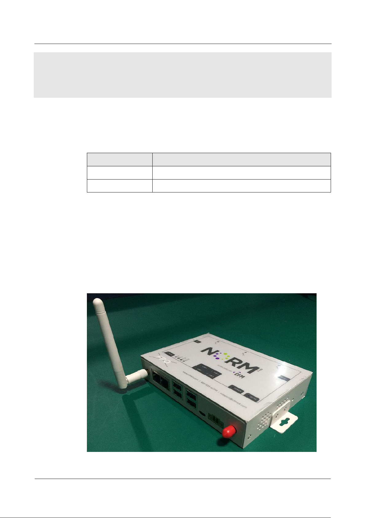
Appearance
2 Product structure
Figure 2-1 EIS6500 Embedded Server
Page 14

H8922 4G Router
2 Product structure
(2012-09-14)
2 -5
Size
Model
Dimension (mm)
Interface
EIS6500
Embedded
Server
145mX103.3X29
2×100/1000Mb LAN interface
1×10/100Mb WAN interface
2× RS-232 port(DB9)
1× RS-232 console port(DB9)
4× USB2.0
1× Micro USB port(OTG)
1× RSMA-K antenna interface Wi-Fi
1× Standard DC power interface
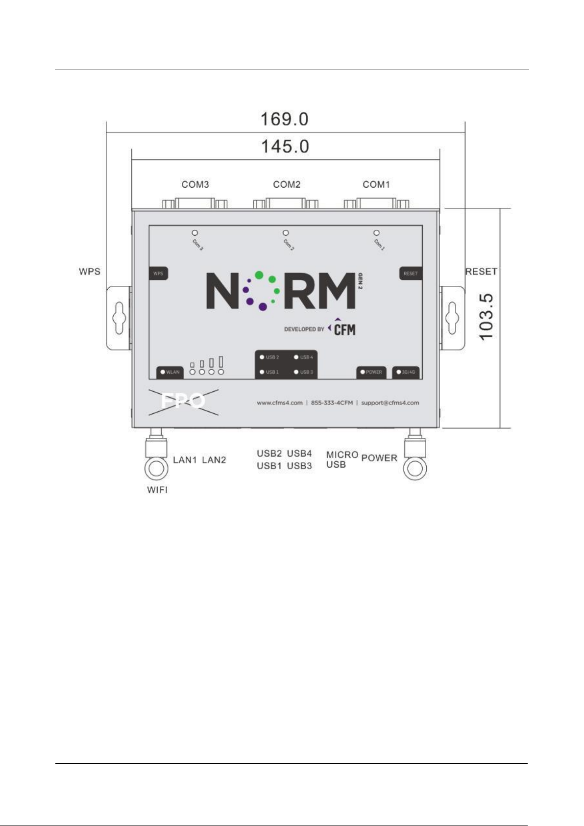
Figure 2-2 EIS6500 Embedded Server
EIS6500 Embedded Server appearance as Figure 2-3
Page 15
2 Product structure
H8922 4G Router
2 -6
(2012-09-14)
Figure 2-3 EIS6500 Embedded Server Figure
Page 16
H8922 4G Router
2 Product structure
(2012-09-14)
2 -7
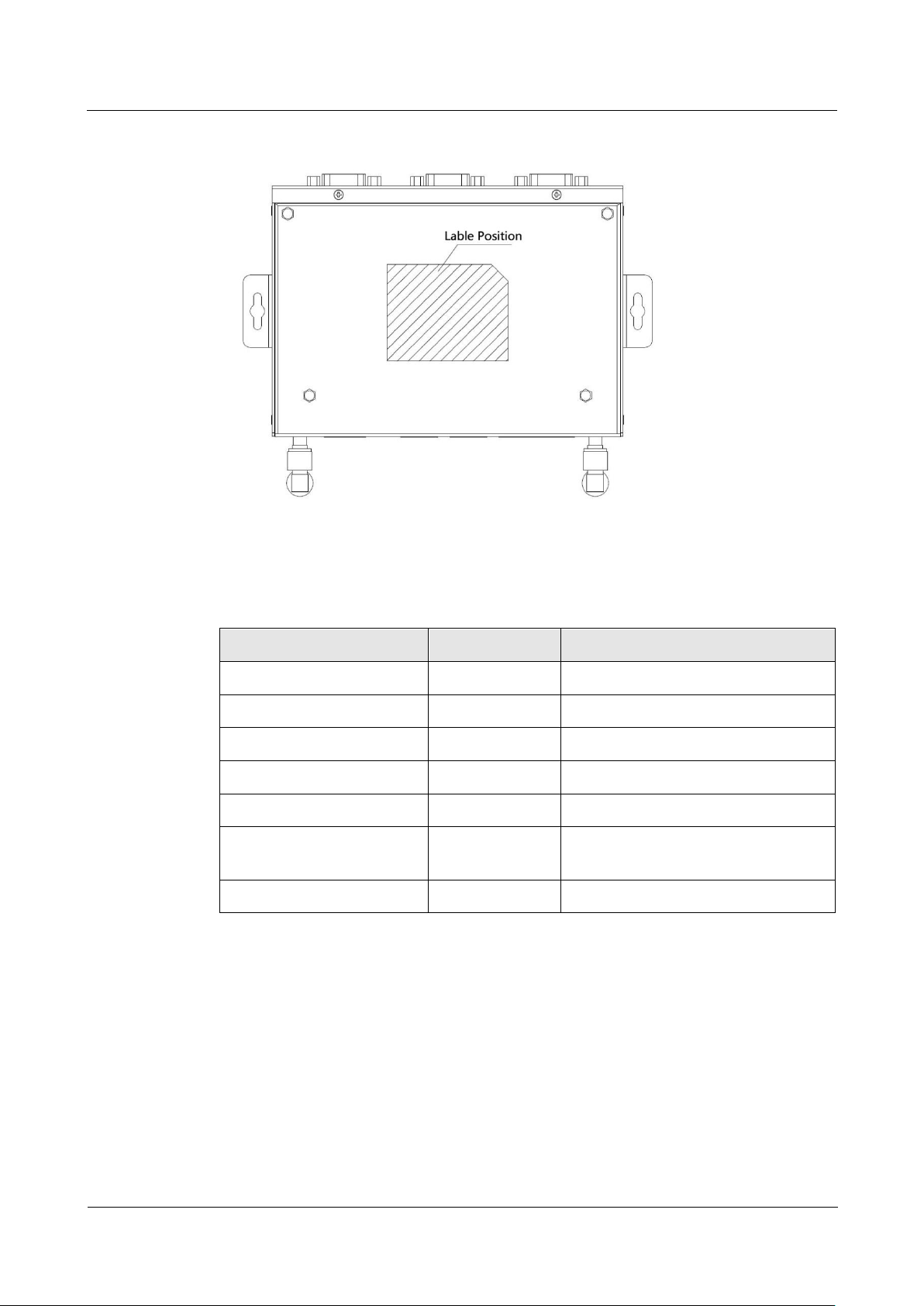
Figure 2-4 EIS6500 Embedded Server bottom view
Accessories name
Number
Note
EIS6500 Embedded Server
1 pcs
CD-ROM
1 pcs
Optional
Wi-Fi antenna
1 pcs
2.4G
RJ45 cable
1 pcs
Mounting
1 pair
Certificate and warranty
card
1 pcs
+12V power adapter
1 pcs
2.1.2 Accessories
Table 2-1 EIS6500 Embedded Server accessories
Page 17
2 Product structure
H8922 4G Router
2 -8
(2012-09-14)
2.2 Structure
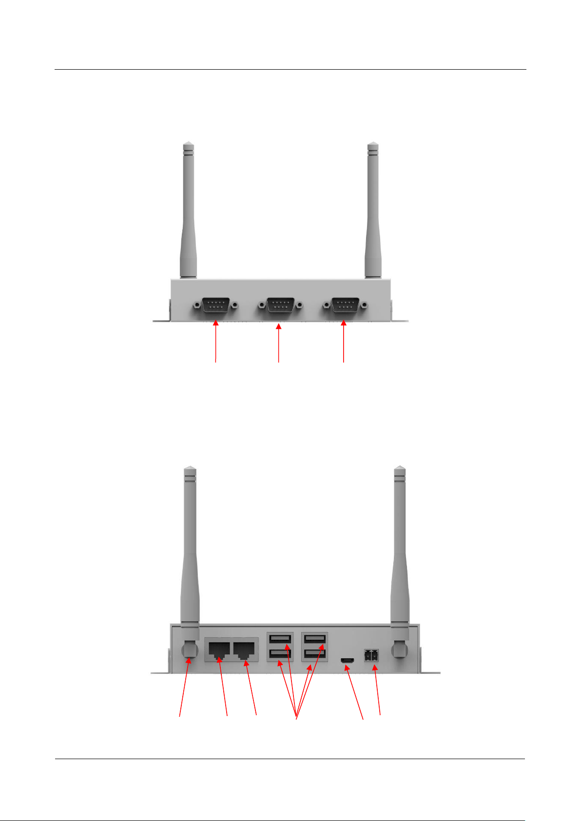
Figure 2-5 Front panel
com1 com2 com3
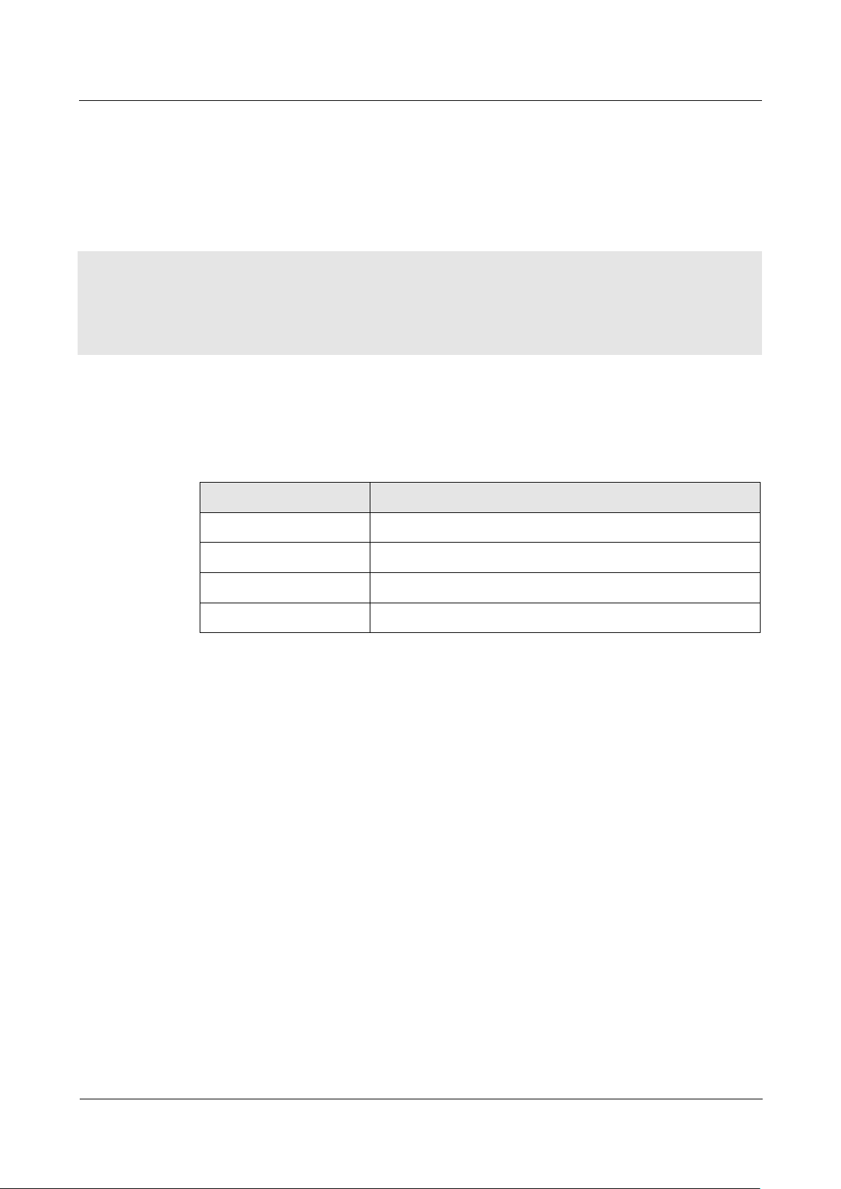
Figure 2-6 Back panel
Wi-Fi ANT LAN1 LAN2 USB OTG Power
Page 18
H8922 4G Router
3 Installation of EIS6500 Embedded Server
(2012-09-14)
3 -9
3 Installation of EIS6500 Embedded Server
Chapter
Content
3.1 Unpacking
Unpack EIS6500 Embedded Server box and the packing list.
3.2 How to install
How to install EIS6500 Embedded Server Ethernet cable .etc.
3.3 Power supply
Power supply needs of EIS6500 Embedded Server.
3.4 Review
Review
About this chapter
3.1 Unpacking
After received the box of EIS6500, please unpack it and check if all accessories complete.
Please check as reference.
3.2 How to install
3.2.1 Ethernet cable connection
Use Ethernet port directly connect EIS6500 Embedded Server and computer, or transferred
by a switch.
Page 19

3 Installation of EIS6500 Embedded Server
H8922 4G Router
3 -10
(2012-09-14)
3.2.2 Serial port connection.
When you connect EIS6500 Embedded Server to serial port on laptop or other device. To do
this you need a serial port cable, this cable is optional. One end connect to computer serial
port, other end connect the console port on EIS6500
This port for other application, not for Console.
3.3 Power supply
EIS6500 Embedded Server adapt voltage input: +12VDC, support hot plug and complex
application environment.
3.4 Review
After connect Ethernet cable, necessary antenna, then connect power cable.
Notice
Please connect antenna before connect power cable, otherwise because of Impedance
mismatching, signal maybe poor.
Step 1 Check antenna connection.
Step 2 Power on EIS6500 Embedded Server, take it as a example:
After connect power, Power LED solid light, means server system start.
After connect usb1/2/3/4, USB1/2/3/4 LED solid light, means USB found the device.
After connect com1/2/3, com1/2/3 LED blinking quickly means data transmission start.
After connect Access Point, WLAN LED solid light, and Signal led shows the signal
level.
Page 20

H8922 4G Router
4 Before configure
Version (2012-09-14)
4 -1
About this chapter
Chapter
Content
4.1 LED Status
The meaning of LED status.
4.2 Local configure
How to local configure EIS6500 Embedded Server.
LED name
Status
Power
GREEN - Power on
Green flashes - System running well.
OFF - no power supplied
RED- some wrong happened
WLAN
AMBER flashes - RX/TX packets on the WLAN
OFF - WLAN interface is inactive
RED- some wrong happened
WLAN signal
4 Green light - >= -65 dBm
3 Green light - -70 ~ -65 dBm
2 Green light - -75 ~ -70 dBm.
1 Green light - -80 ~ -75dBm.
All Off - <= -80 dBm.
USB1~4
GREEN - light when a USB device is connected.
GREEN FLASH – DATA RX/TX THROUGH THE USB device.
OFF - no USB device connected.
4.1 LED Status
There are LED on front panel of EIS6500 Embedded Server, they show how EIS6500
Embedded Server works.
Table 4-1 LED instruction
4 Before configure
Page 21

4 Before configure
H8922 4G Router
4 -2
(2012-09-14)
LED name
Status
COM1~3
GREEN flashes - RX data
AMBER - TX data
OFF - no TX/RX data Blinking quickly(2s): dialing
Dark:No module or no auto-dial
4.2 Local configure
Precondition
Already power on EIS6500 Embedded Server
Ethernet cable connect to EIS6500 Embedded Server
You could specify a static IP or DHCP get IP for your computer.
Console port
For network server, this device do not supply VGA/HDMI/DVI etc. display port. But this
server supply console port using com1.
Connect com1 using RS232 cable to computer, and run terminal application, power EIS6500,
you can login as normal user or root. For example:
Login: linaro
Password: linaro
$sudo root
#
Page 22

H8922 4G Router
5 FAQ
Version (2012-09-14)
5 -3
About this chapter
Chapter
Content
5.1 Hardware failure
Possible hardware failure during using EIS6500 Server and
how to handle them.
5.1 Hardware Failure
5.1.1 All LED dark
Phenomenon
5 FAQ
Server LED all dark.
Possible Reason
Power supply does not match, it should be 12VDC
No power supply
Solution
Make sure the power supply is 12VDC
Check the power adapter and cable connection.
5.1.2 Ethernet Connection
Phenomenon
LAN LED dark
Possible Reason
Ethernet cable connection problem
Ethernet cable damage
PC end network card abnormal
Page 23

5 FAQ
H8922 4G Router
5 -4
(2012-09-14)
Solution
Re-connect Ethernet cable
Change a Ethernet cable
Check network card setting on PC end
5.1.3 Antenna Connection
Phenomenon
Cannot connect antenna
Possible Reason
Antenna type do not match
Wrong connection
Solution
Please check antenna interface, should be R-SMA
Please check antenna type, there are WI-FI, do not mix them.
5.1.4 No Signal
Phenomenon
Possible Reason
Solution
EIS6500 WLAN signal led status show no signal.
Antenna connect wrong
Connect suitable antenna
Check if connect to Access Point with correct account and password
When Server is power on, press and hold RESET button around 1s, server will reboot and
kept all setting.
Page 24

 Loading...