

Page 1
®
Vision
Components
®
The Smart Camera People
VC4XXX Operating Ma nual
Hardware Specifications and special Software Functions of
VC40XX and VC44XX Smart Cameras
Revision 3.3 – 23 Jul 2014
Document name: VC4XXX_HW.pdf
Vision Components GmbH Ettlingen, Germany
Page 2
VC4XXX_HW.pdf – Hardware Documentation VC4XXX Smart Cameras
1996-2014 Vision Components GmbH Ettlingen, Germany
2
Foreword and Disclaimer
This documentation has been prepared with most possible care. However Vision Components GmbH
does not take any liability for possible errors. In the interest of progress, Vision Components GmbH
reserves the right to perform technical changes without further notice.
Please notify support@vision-components.com if you become aware of any errors in this manual or
if a certain topic requires more detailed documentation.
This manual is intended for information of Vision Component’s customers only. Any publication of this
document or parts thereof requires written permission by Vision Components GmbH.
Trademarks
Code Composer Studio and TMS320C6000, Windows XP, Total Commander, Tera Term, Motorola
are registered Trademarks. All trademarks are the property of their respective owners.
References
Since the VC4XXX smart camera family employs a TI processor, the programming environment and
functions for the VC20XX cameras can be used for this camera.
Further References under “Support + Download ” on www.vision-components.com:
„Support News“ – for up to date information on VC Software and Documentation.
„Knowledge Base / FAQ“ - searchable Database with latest software developments, frequently asked
questions and demo programs.
“Download Areas” for all documentation and Software downloads – refer to the following table:
Description Title on Website Download Center
Introduction to VC Smart Camera
programming
Programming Tutorial for
VC20XX and VC40XX Cameras
Service & Support
Download Center
Documentation Getting Started VC
Demo programs and sample code
used in the Programming Tutorial
Tutorial_Code
Service & Support
Download Center
Documentation Getting Started VC
VC4XXX Hardware Manual
VC4XXX Smart Cameras
Hardware Documentation
Service & Support
Download Center
Documentation Hardware
VCRT Operation System Functions
Manual
VCRT 5.0 Software Manual
Service & Support
Download Center
Documentation Software
VCRT Operation System TCP/IP
Functions Manual
VCRT 5.0 TCP/IP Manual
Service & Support
Download Center
Documentation Software
VCLIB 3.0 Image Processing Library
Manual
VCLIB 3.0 Software Manual
Service & Support
Download Center
Documentation Software
The Light bulb highlights hints and ideas that may be helpful for a development.
This warning sign alerts of possible pitfalls to avoid. Please pay careful attention to sections
marked with this sign.
Author: VC Support, mailto:support@vision-comp.com
!
Page 3

VC4XXX_HW.pdf – Hardware Documentation VC4XXX Smart Cameras
1996-2014 Vision Components GmbH Ettlingen, Germany
3
Table of Contents
1
General Information 5
2 Feature Overview Smart Camera Families 6
3 Technical Specifications “VC Base” 8
3.1 Technical Specifications VC4018 8
3.2 Technical Specifications VC4016 9
4 Technical Specifications “VC Professional” 10
4.1 Technical Specifications VC4038 10
4.2 Technical Specifications VC4058 11
4.3 Technical Specifications VC4065 11
4.4 Technical Specifications VC4066 13
4.5 Technical Specifications VC4067 & VC4067NIR 14
4.6 Technical Specifications VC4068 15
5 Technical Specifications “VC Optimum” 16
5.1 Technical Specifications VC4438 16
5.2 Technical Specifications VC4458 17
5.3 Technical Specifications VC4459 18
5.4 Technical Specifications VC4465 19
5.5 Technical Specificat ions V C446 5C 20
5.6 Technical Specifications VC4466 21
5.7 Technical specifications VC4467 & VC4467NIR 22
5.8 Technical Specifications VC4468 23
5.9 Technical Specifications VC4472 24
6 VC4XXX Camera Interfaces 25
6.1 LAN / Ethernet Interface 26
6.1.1 Pin Assignments LAN / Ethernet Interface 26
6.1.2 Available Accessories for LAN / Ethernet socket 26
6.2 Trigger-/ V24- (RS232)-/ Keypad- / Encoder Interface 27
6.2.1 Pin Assignments Trigger-/ V24 (RS232)-/ Keypad/ - Encoder Interface 28
6.2.2 Trigger Cable 28
6.2.3 V24 (RS232) serial Cable 29
6.2.4 Y-Cable 29
6.2.5 Electrical Specifications of Trigger- / Serial-/ Keypad / Encoder Interface 30
6.3 Power Supply and IO Interface 33
6.3.1 Pin assignments Power Supply and IO Interface 33
6.3.2 Electrical specifications Camera Power Supply Camera 33
6.3.3 Shutdown Function for VC Professional and VC Optimum 34
6.3.4 Electrical Specifications digital PLC IO Interface 35
6.3.5 Available Accessories / Cables for Power Supply and IO Interface 36
6.4 Video Output Interface 37
6.4.1 Pin Assignment of Video Output Interface 37
Page 4

VC4XXX_HW.pdf – Hardware Documentation VC4XXX Smart Cameras
1996-2014 Vision Components GmbH Ettlingen, Germany
4
6.4.2 Available Accessories / Cables for Video Output Interface 37
7 Order Numbers Cameras and Accesso ries 38
7.1 Order numbers of all available VC4XXX Camera Models: 38
7.1.1 Order Numbers “VC Base” Models: 38
7.1.2 Order Numbers “VC Professional” Models: 38
7.1.3 Order Numbers “VC Optimum” Models: 38
7.2 Order numbers of all available VC4XXX Accessories 39
8 Programming VC4 XX X S m art Cam eras 43
8.1 Programming the additional Serial Interface 43
8.2 Programming the Encoder Interface 44
Appendix A: Block diagram VC40XX Smart Cameras A
Appendix B: Block diagram VC4018/ -16 Smart Cameras A
Appendix C: Dimensions VC Base (VC4018 and VC4016) B
Appendix D: Dimensions VC Profess ional and VC Optimum models B
Appendix E: Drawing Camera Head VC40XX and VC44XX C
Appendix F: Spectral Transmission of IR Filter D
Page 5
VC4XXX_HW.pdf – Hardware Documentation VC4XXX Smart Cameras
1996-2014 Vision Components GmbH Ettlingen, Germany
5
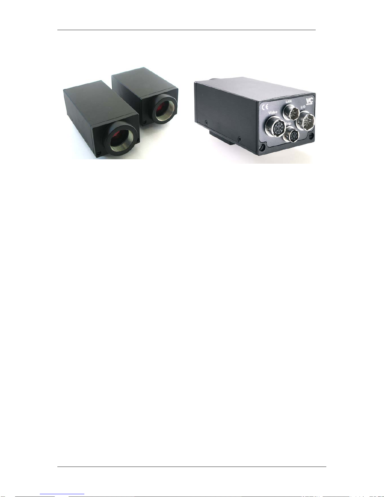
1 General Information
Standard and short VC4XXX housing
VC4XXX Smart Camera series rear view
The new VC4XXX Smart Camera generation from Vision Components succeeds the VC20XX product
line. The model variety of the VC20XX range has been extended further – from formerly 6 different
models to 12 (not counting color camera versions or doubling VC20XX serial / Ethernet versions).
In contrast to the VC20XX generation, the VC4XXX cameras are based on 3 different hardware
platforms with different processor performance, interfaces and programming features. This allows
even more to select the right smart camera for every application. The following section includes a
feature overview for all cameras for easier product selection.
The proven industrial housing and connectors of the VC20XX series has been kept for the new model
line. Together with the almost complete software compatibility this will aide the upgrade of existing
applications. For the new “VC Base Family range” it was possible to shorten the camera housing even
further, offering a complete vision system with a very small form factor.
Responding to customer demand, the VC4XXX features both – 100 Mbit Etherne t and an add itiona l
V24 (RS232) Interface. The RS232 interface connects to the Trigger socket. For this reason the
trigger input had to be slightly modified – existing trigger input circuits requires therefore adjustment.
From July 2006 all VC Pr of es siona l and VC Optimum models feature a incremental encoder input
allowing accurate synchronization of image acquisition with moving machinery for instance conveyor
belts.
Please refer to section 6.2 for details. All other interfaces have remained unchanged.
Page 6

VC4XXX_HW.pdf – Hardware Documentation VC4XXX Smart Cameras
1996-2014 Vision Components GmbH Ettlingen, Germany
6
2 Feature Overview Smart Camera Families
This manual describes 3 different Smart Camera families:
1. VC Base Family:
VC4018 and VC4016 Smart Cameras that are based on the VCSBC Hardware. These models
feature an even more compact housing than the VC Professional and Optimum VC Smart
Camera range. Although the VC4016 and VC4018 cameras omit features like the VGA output,
they still incorporate a powerful 400 MHz DSP, opto-isolated digital SPS IO’s, a high speed
trigger as well as 100 Mbit Ethernet and an additional R S232 serial interface. Both cameras
are also available with color sensor (Bayer filter).
In summary: The VC4018 and VC4016 are a very cost efficient solution if certain features are
not required.
2. VC Professional Family:
The VC4038 to VC4068 include all the standard features of a typical VC Smart Camera and
more. These models offer the largest variety of sensor resolutions, frame rates, shutter values
and interfaceability. The latest example is the new high speed encoder interface, that allows
accurate image synchronization with moving equipment. The VC Professional VC40XX range
also supports a number of new software features like internal events.
In summary: The variety and versatility of the VC Professional VC40XX range offers a
solution for almost every application.
3. VC Optimum Family:
The VC44XX feature the 1 GHz Ti C644X processor with 8000MIPS – made for applications
that require the maximum calculation power available in a vision system today. Further
additional features compared with the VC Pro f es s ional Family are: 64 Mbyte DRAM memory,
CCD resolutions of up to 2 mega pixel and frame rates of up to 250 fps (500 fps in binning
mode).
The high speed trigger input of all VC4XXX family allows jitter free taking – even when inspectin g fast
moving objects. As the previous generation the VC4XXX also includes 24 V digital IO’s and the VC
Professional and VC Optimum cameras incorporat e a direct video output.
As with all VC Smart Cameras with Texas Instruments DSP, the operation system VCRT allows multitasking. This means for instance that user interface commands can execute in parallel without
stopping the inspection process. It is also possible to transfer live images via TCP/IP using a
background task.
Image acquisition can be done in the camera background. The VC4XXX allow to perform the three
tasks of image capture, image transfer and image processing in parallel, greatly increasing the amount
of processed images per second.
The 1GHz TMS320C64 DSP is one of the fastest DSPs available. It features a RISC-like instruction
set, up to 8 instructions can be executed in parallel, two L1 cache memories (32 Kbytes each) and a
256 kB L2 cache on chip. Its high speed 64-channel DMA controller gives additional performance. The
DSP uses fast external SDRAM as main memory. A flash EPROM provides non-volatile memory.
Page 7
VC4XXX_HW.pdf – Hardware Documentation VC4XXX Smart Cameras
1996-2014 Vision Components GmbH Ettlingen, Germany
7
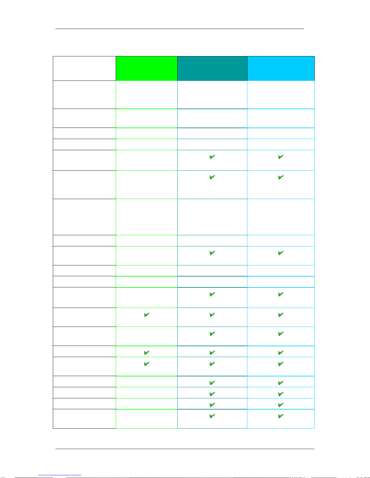
Feature comparison of the VC4XXX Smart Camera Families:
Features: VC Base Family
VC4018 and VC4016
VC Professional Family
VC4038 to VC4068
VC Optimum Family
VC4438 to VC4472
Processor
400MHz TMS320C64
DSP 32bit,
3200 MIPS
400MHz TMS320C64
DSP 32bit,
3200 MIPS
1GHz TMS320C64 DSP
64 bit,
8000 MIPS
Memory Bandwidth
(useable bandwidth)
400 Mbyte / sec 400 Mbyte / sec 800 Mbyte / sec
SDRAM
32 Mbyte 32 Mbyte 64 Mbyte
Flash Memory
4 Mbyte 4 Mbyte 4 Mbyte
SD card
2 GB
2 GB
VGA Output
No
Live image transfer to
PC via Ethernet
SVGA / SXGA Video
output integrated
SVGA / SXGA Video
output integrated
Digital IO’s
4 Inputs / 4 Outputs
up to 4x 400mA
NOT separated fom
power supply
4 Inputs / 4 Outputs up
to 4x 500mA
Separated fom power
supply
Inputs / 4 Outputs up to
4x 500mA
Separated fom power
supply
Supply Voltage
12…24V 24V 24V
Power interruption
detection (see 6.3.2)
High Speed Shutter
Down to 36µsec Down to 5µsec Down to 5µsec
Frames per Second
Up to 32 Up to 242 Up to 242
Binning Mode
2 times (up to 484 fps) 2 times (up to 484 fps)
Hardware Trigger
Input (jitter free)
High-speed Encoder
Interface
100 Mbit Ethernet
RS232 Serial
Interface
Real time clock
Temperature sensor
Trigger Event
Programmable Input
Lookup Table
Refer to the Appendix A and B for hardware structure diagrams of VC Base, VC Professional and VC
Optimum Famil y Smart Cameras.
Page 8

VC4XXX_HW.pdf – Hardware Documentation VC4XXX Smart Cameras
1996-2014 Vision Components GmbH Ettlingen, Germany
8
3 Technical Specifications “VC Base”
3.1 Technical Specifications VC4018
Component / Feature Specification
CCD Sensor:
1/3" SONY ICX424AL - also available with color sensor (Bayer Filter)
Active pixels:
640(H) x 480(V)
Pixel size:
7.4(H) x 7.4(V) µm
Active sensor size:
4.74(H) x 3.55(V) mm
High-speed shutter: 36.2, 98.6, 161 microseconds, increasing with steps of 62.4
microseconds (full-frame shutter)
Low-speed shutter: up to 2 sec. adjustable integration time
Integration: full-frame
Picture taking: program-controlled, trigger controlled (interrupt); full-frame / 32 frames
per second, external high speed trigger
Clamping: zero offset digital clamping
A/D conversion: 12.5 MHz / 10 bit, only the 8 most significant bits used for grey values
Input LUT none
Image Display Via 100 Mbit Ethernet onto PC
Processor: Texas Instruments 400 MHz TMS320 C64 DSP
RAM: 32 Mbytes SDRAM (synchronous dynamic RAM)
Memory capacity: Up to 100 full-size images in format 640x480
Flash EPROM: 4 Mbytes flash EPROM (nonvolatile memory) for programs and data, in-
system programmable, 3 MB available to user
MMC: Not available
Process interface: 4 inputs / 4 outputs, outputs 4x400 mA
Trigger Input Fast 5 V TTL input and output, jitter free image acquisition
Serial Interface: 115,200 bd serial RS232 communication port
Ethernet interface: 100 Mbit
Video output No direct video output / download of live images via Ethernet possible
CE certification: CE Certification from Vision Components
Storage Conditions Temperature: -20 to 60 deg C, Max. humidity: 90%, non condensing.
Operating Conditions Temperature: 0… +50 deg C (housing temperature), Max. humidity:
80%, non condensing.
Power Supply 24V +/-20% DC
Power Consumption ≈3 W (current drawn from PLC outputs additional)
Page 9

VC4XXX_HW.pdf – Hardware Documentation VC4XXX Smart Cameras
1996-2014 Vision Components GmbH Ettlingen, Germany
9
3.2 Technical Specifications VC4016
Component / Feature Specification
CCD Sensor:
1/3" SONY ICX204 AL - also available with color sensor (Bayer Filter)
Active pixels:
1024 (H) x 768 (V)
Pixel size:
4.65 (H) x 4.65 (H) µm
Active sensor size:
4.76(H) x 3.57(V) mm
High-speed shutter: From 46.7, 122.9, 199.1 microseconds, increasing with steps of 76.2
microseconds (full-frame shutter)
Low-speed shutter: up to 2 sec. adjustable integration time
Integration: full-frame
Picture taking: program-controlled, trigger controlled (interrupt); full-frame / 16.7 frames
per second, external high speed trigger
Clamping: zero offset digital clamping
A/D conversion: 16.7 MHz / 10 bit, only the 8 most significant bits used for grey values
Input LUT none
Image Display Via 100 Mbit Ethernet onto PC
Processor: Texas Instruments 400 MHz TMS320 C64 DSP
RAM: 32 Mbytes SDRAM (synchronous dynamic RAM)
Memory capacity: Up to 100 full-size images in format 1024x768
Flash EPROM: 4 Mbytes flash EPROM (nonvolatile memory) for programs and data, in-
system programmable, 3 MB available to user
MMC: Not available
Process interface: 4 inputs / 4 outputs, outputs 4x400 mA
Trigger Input Fast 5 V TTL input and output, jitter free image acquisition
Serial Interface: 115,200 bd serial RS232 communication port
Ethernet interface: 100 Mbit
Video output No direct video output / download of live images via Ethernet possible
CE certification: CE Certification from Vision Components
Storage Conditions Temperature: -20 to 60 deg C, Max. humidity: 90%, non condensing.
Operating Conditions Temperature: 0… +50 deg C (housing temperature), Max. humidity:
80%, non condensing.
Power Supply 24V +/-20% DC
Power Consumption ≈3 W (current drawn from PLC outputs additional)
Page 10
VC4XXX_HW.pdf – Hardware Documentation VC4XXX Smart Cameras
1996-2014 Vision Components GmbH Ettlingen, Germany
10
4 Technical Specifications “VC Professional”
4.1 Technical Specifications VC4038
Component / Feature Specification
CCD Sensor:
1/3 “ SONY ICX424AL
Active pixels:
640(H) x 480(V)
Pixel size:
7.4 µm (H) x 7.4 µm (V)
Active sensor size:
4.74(H) x 3.55(V) mm
Integration: full-frame progressive scan
Picture taking: program-controlled or triggered externally; full-frame /
63 frames per second
Binning 2 times binning, 126 frames/s, 640(H) x 240(V)
Shutter 5µs, 10 µs, 15 µs, 19 µs, … + steps of 31 up to 8s
Clamping: zero offset digital clamping
A/D conversion: 1 x 25 MHz / 10 bit
Input LUT
1024x8 bit (10bit → 8 bit)
Image display: black-and-white, Pseudo Color from color lookup table 3x8Bit RGB,
live image, still image, graphics
Overlay: 8-bit overlay with LUT, maskable
Processor: Texas Instruments 400 MHz TMS320 C64 DSP
RAM: 32 MByte
Flash EPROM: 4 MByte
SD card 2 GB
Process interface: 4 inputs / 4 outputs, optically decoupled 24 V, outputs 4x500 mA
Trigger input: Fast 5 V TTL input and output, jitter free image acquisition
Ethernet interface: 100Mbit Ethernet
Serial Interface: 115,200 bd serial RS232 communication port
Video output (VESA
Standard):
Resolution: 800x600, horizontal / vertical frequency: 48.08 / 72.19
Hz, pixel frequency: 50 MHz, RGB, 3x75 Ohm, 1 Vpp, SVGA
output, HSYNC, VSYNC separate
Storage Conditions Temperature: -20 to 60 deg C, Max. humidity: 90%, non cond.
Operating Conditions Temperature: 0… +50 deg C (housing temperature), Max.
humidity: 80%, non condensing.
Power Supply /
Consumption
24V / max 5 W, digital IOs supplied additionally
Page 11
VC4XXX_HW.pdf – Hardware Documentation VC4XXX Smart Cameras
1996-2014 Vision Components GmbH Ettlingen, Germany
11
4.2 Technical Specifications VC4058
Component / Feature Specification
CCD Sensor:
1/3”Kodak KAI-0340
Active pixels:
640(H) x 480(V)
Pixel size:
7.4 µm (H) x 7.4 µm (V)
Active sensor size:
4.74(H) x 3.55(V) mm
Integration: full-frame progressive scan
Picture taking: program-controlled or triggered externally; full-frame /
242 frames per second
Binning 2 times binning, 484 frames/s, 640(H) x 240(V)
Shutter 5µs, 10 µs, 15 µs, 19 µs, … + steps of 8.5 µs up to 2,2s
Clamping: zero offset digital clamping
A/D conversion: 2 x 50 MHz / 10 bit
Input LUT
1024x8 bit (10bit → 8 bit)
Image display: black-and-white, Pseudo Color from color lookup table 3x8Bit RGB,
live image, still image, graphics
Overlay: 8-bit overlay with LUT, maskable
Processor: Texas Instruments 400 MHz TMS320 C64 DSP
RAM: 32 MByte
Flash EPROM: 4 MByte
SD card 2 GB
Process interface: 4 inputs / 4 outputs, optically decoupled 24 V, outputs 4x500 mA
Trigger input: Fast 5 V TTL input and output, jitter free image acquisition
Ethernet interface: 100Mbit Ethernet
Serial Interface: 115,200 bd serial RS232 communication port
Video output (VESA
Standard):
Resolution: 800x600, horizontal / vertical frequency: 48.08 / 72.19
Hz, pixel frequency: 50 MHz, RGB, 3x75 Ohm, 1 Vpp, SVGA
output, HSYNC, VSYNC separate
Storage Conditions Temperature: -20 to 60 deg C, Max. humidity: 90%, non cond.
Operating Conditions Temperature: 0… +50 deg C (housing temperature), Max.
humidity: 80%, non condensing.
Power Supply /
Consumption
24V / max 5 W, digital IOs supplied additionally
From june 2014 this camera is not available anymore. It has been replaced by the VC4459.
!
Page 12
VC4XXX_HW.pdf – Hardware Documentation VC4XXX Smart Cameras
1996-2014 Vision Components GmbH Ettlingen, Germany
12
4.3 Technical Specifications VC4065
Component / Feature Specification
CCD Sensor:
1/2" SONY ICX415AL
Active pixels:
768(H) x 582(V)
Pixel size:
8.3(H) x 8.3(V) µm
Active sensor size:
6.37(H) x 4.83(V) mm
Integration: full-frame progressive scan
Picture taking: program-controlled or triggered externally; full-frame /
55 frames per second
Binning 2 times binning, 110 frames / s, 782(H) x 291(V)
Shutter 5µs, 10 µs, 15 µs, 20 µs,… + steps of 28.5 µs up to 7.4s
Clamping: zero offset digital clamping
A/D conversion: 1 x 33 MHz / 10 bit
Input LUT
1024x8 bit (10bit → 8 bit)
Image display: black-and-white, Pseudo Color from color lookup table 3x8 Bit
RGB, live image, still image, graphics
Overlay: 8-bit overlay with LUT, maskable
Processor: Texas Instruments 400 MHz TMS320 C64 DSP
RAM: 32 MByte
Flash EPROM: 4 MByte
SD card 2 GB
Process interface: 4 inputs / 4 outputs, optically decoupled 24 V, outputs 4x500 mA
Trigger input: Fast 5 V TTL input and output, jitter free image acquisition
Ethernet interface: 100 Mbit Ethernet
Serial Interface: 115,200 bd serial RS232 communication port
Video output (VESA
Standard):
Resolution: 800x600, horizontal / vertical frequency: 48.08 / 72.19
Hz, pixel frequency: 50 MHz, RGB, 3x75 Ohm, 1 Vpp, SVGA
output, HSYNC, VSYNC separate
Storage Conditions Temperature: -20 to 60 deg C, Max. humidity: 90%, non cond.
Operating Conditions Temperature: 0… +50 deg C (housing temperature), Max.
humidity: 80%, non condensing.
Power Supply / Consumption 24V / max 5 W, digital IOs s upplied additionally
Page 13
VC4XXX_HW.pdf – Hardware Documentation VC4XXX Smart Cameras
1996-2014 Vision Components GmbH Ettlingen, Germany
13
4.4 Technical Specifications VC4066
Component / Feature Specification
CCD Sensor:
1/3" SONY ICX204AL
Active pixels:
1024(H) x 768(V)
Pixel size:
4.65(H) x 4.65(V) µm
Active sensor size:
4.76(H) x 3.57(V) mm
Integration: full-frame progressive scan
Picture taking: program-controlled or triggered externally; full-frame /
20 frames per second
Binning 2 times binning, 40 frames/s, 1024(H) x 384(V)
Shutter 10 µs, 15 µs, 20 µs, …+ steps of 61.5 µs up to 16,2s
Clamping: zero offset digital clamping
A/D conversion: 1 x 20 MHz / 10 bit
Input LUT
1024x8 bit (10bit → 8 bit)
Image display: black-and-white, Pseudo Color from color lookup table 3x8 Bit
RGB, live image, still image, graphics
Overlay: 8-bit overlay with LUT, maskable
Processor: Texas Instruments 400 MHz TMS320 C64 DSP
RAM: 32 MByte
Flash EPROM: 4 MByte
SD card 2 GB
Process interface: 4 inputs / 4 outputs, optically decoupled 24 V, outputs 4x500 mA
Trigger input: Fast 5 V TTL input and output, jitter free image acquisition
Ethernet interface: 100Mbit Ethernet
Serial Interface: 115,200 bd serial RS232 communication port
Video output (VESA
Standard):
Resolution: 1280x1024, horizontal / vertical frequency: 63.98 /
60.02 Hz, pixel frequency: 108 MHz, RGB, 3x75 Ohm, 1 Vpp,
SVGA output, HSYNC, VSYNC separate
Storage Conditions Temperature: -20 to 60 deg C, Max. humidity: 90%, non cond.
Operating Conditions Temperature: 0… +50 deg C (housing temperature), Max.
humidity: 80%, non condensing.
Power Supply / Consumption 24V / max 5 W, digital IOs s uppl ied additionally
Page 14
VC4XXX_HW.pdf – Hardware Documentation VC4XXX Smart Cameras
1996-2014 Vision Components GmbH Ettlingen, Germany
14
4.5 Technical Specifications VC4067 & VC4067NIR
Component / Feature Specification
CCD Sensor:
2/3" SONY ICX285AL EXview HAD CCD
Active pixels:
1280(H) x 1024 (V)
Pixel size:
6.45(H) x 6.45(V) µm
Active sensor size:
8.26(H) x 6.60(V) mm
Integration: full-frame progressive scan
Picture taking: program-controlled or triggered externally; full-frame /
14 frames per second
Binning 2 times binning, 28 frames/s, 1280(H) x 1024(V)
Shutter 5 µs, 10µs, 15 µs,20 µs + steps of 67 µs up to 17.59s
Clamping: zero offset digital clamping
A/D conversion: 1 x 25 MHz / 10 bit
Input LUT
1024x8 bit (10bit → 8 bit)
Image display: black-and-white, Pseudo Color from color lookup table 3x8 Bit
RGB, live image, still image, graphics
Overlay: 8-bit overlay with LUT, maskable
Processor: Texas Instruments 400 MHz TMS320 C64 DSP
RAM: 32 MByte
Flash EPROM: 4 MByte
SD card 2 GB
Process interface: 4 inputs / 4 outputs, optically decoupled 24 V, outputs 4x500 mA
Trigger input: Fast 5 V TTL input and output, jitter free image acquisition
Ethernet interface: 100Mbit Ethernet
Serial Interface: Additionna 115,200 bd serial RS232 communication port
Video output (VESA
Standard):
Resolution: 1280x1024, horizontal / vertical frequency: 63.98 /
60.02 Hz, pixel frequency: 108 MHz, RGB, 3x75 Ohm, 1 Vpp,
SVGA output, HSYNC, VSYNC separate
Storage Conditions Temperature: -20 to 60 deg C, Max. humidity: 90%, non cond.
Operating Conditions Temperature: 0… +50 deg C (housing temperature), Max.
humidity: 80%, non condensing.
Power Supply / Consumption 24V / max 5 W, digital IOs s uppl ied additionally
Page 15

VC4XXX_HW.pdf – Hardware Documentation VC4XXX Smart Cameras
1996-2014 Vision Components GmbH Ettlingen, Germany
15
4.6 Technical Specifications VC4068
Component / Feature Specification
CCD Sensor:
1/2" SONY ICX205A
Active pixels:
1280(H) x 1024 (V)
Pixel size:
4.65(H) x 4.65(V) µm
Active sensor size:
5.95(H) x 4.76(V) mm
Integration: full-frame progressive scan
Picture taking: program-controlled or triggered externally; full-frame /
14 frames per second
Binning 2 times binning, 28 frames/s, 1280(H) x 1024(V)
Shutter 5 µs, 10µs, 15 µs,20 µs + steps of 67 µs up to 17.59s
Clamping: zero offset digital clamping
A/D conversion: 1 x 25 MHz / 10 bit
Input LUT
1024x8 bit (10bit → 8 bit)
Image display: black-and-white, Pseudo Color from color lookup table 3x8 Bit
RGB, live image, still image, graphics
Overlay: 8-bit overlay with LUT, maskable
Processor: Texas Instruments 400 MHz TMS320 C64 DSP
RAM: 32 MByte
Flash EPROM: 4 MByte
SD card 2 GB
Process interface: 4 inputs / 4 outputs, optically decoupled 24 V, outputs 4x500 mA
Trigger input: Fast 5 V TTL input and output, jitter free image acquisition
Ethernet interface: 100Mbit Ethernet
Serial Interface: Additionna 115,200 bd serial RS232 communication port
Video output (VESA
Standard):
Resolution: 1280x1024, horizontal / vertical frequency: 63.98 /
60.02 Hz, pixel frequency: 108 MHz, RGB, 3x75 Ohm, 1 Vpp,
SVGA output, HSYNC, VSYNC separate
Storage Conditions Temperature: -20 to 60 deg C, Max. humidity: 90%, non cond.
Operating Conditions Temperature: 0… +50 deg C (housing temperature), Max.
humidity: 80%, non condensing.
Power Supply / Consumption 24V / max 5 W, digital IOs s uppl ied additionally
Page 16
VC4XXX_HW.pdf – Hardware Documentation VC4XXX Smart Cameras
1996-2014 Vision Components GmbH Ettlingen, Germany
16
5 Technical Specifications “VC Optimum”
5.1 Technical Specifications VC4438
Component / Feature Specification
CCD Sensor:
1/3 “ SONY ICX424AL
Active pixels:
640(H) x 480(V)
Pixel size:
7.4 µm (H) x 7.4 µm (V)
Active sensor size:
4.74(H) x 3.55(V) mm
Integration: full-frame
Picture taking: program-controlled or triggered externally; full-frame /
63 frames per second
Binning 2 times binning, 126 frames/s, 640(H) x 240(V)
Shutter 5µs, 10 µs, 15 µs, 19 µs, … steps of 31 up to 8s
Clamping: zero offset digital clamping
A/D conversion: 1 x 25 MHz / 10 bit
Input LUT
1024x8 bit (10bit → 8 bit)
Image display: black-and-white, Pseudo Color from color lookup table 3x8Bit RGB,
live image, still image, graphics
Overlay: 8-bit overlay with LUT, maskable
Processor:
Texas Instruments 1 GHz, 8000 MIPS TMS320 C64 DSP
RAM: 64 MByte
Flash EPROM: 4 MByte
SD card 2 GB
Process interface: 4 inputs / 4 outputs, optically decoupled 24 V, outputs 4x500 mA
Trigger input: Fast 5 V TTL input and output, jitter free image acquisition
Ethernet interface: 100Mbit Ethernet
Serial Interface: 115,200 bd serial RS232 communication port
Video output (VESA
Standard):
Resolution: 800x600, horizontal / vertical frequency: 48.08 / 72.19
Hz, pixel frequency: 50 MHz, RGB, 3x75 Ohm, 1 Vpp, SVGA
output, HSYNC, VSYNC separate
Storage Conditions Temperature: -20 to 60 deg C, Max. humidity: 90%, non cond.
Operating Conditions Temperature: 0… +50 deg C (housing temperature), Max.
humidity: 80%, non condensing.
Power Supply /
Consumption
24V / max 5 W, digital IOs supplied additionally
Page 17

VC4XXX_HW.pdf – Hardware Documentation VC4XXX Smart Cameras
1996-2014 Vision Components GmbH Ettlingen, Germany
17
5.2 Technical Specifications VC4458
Component / Feature Specification
CCD Sensor:
1/3”Kodak KAI-0340
Active pixels:
640(H) x 480(V)
Pixel size:
7.4 µm (H) x 7.4 µm (V)
Active sensor size:
4.74(H) x 3.55(V) mm
Integration: full-frame
Picture taking: program-controlled or triggered externally; full-frame /
242 frames per second
Binning
2 times binning, 484 frames/s, 640(H) x 240(V)
Shutter 5µs, 10 µs, 15 µs, 19 µs, … + steps of 8.5 µs up to 2,2s
Clamping: zero offset digital clamping
A/D conversion: 2 x 50 MHz / 10 bit
Input LUT
1024x8 bit (10bit → 8 bit)
Image display: black-and-white, Pseudo Color from color lookup table 3x8Bit RGB,
live image, still image, graphics
Overlay: 8-bit overlay with LUT, maskable
Processor:
Texas Instruments 1 GHz, 8000 MIPS TMS320 C64 DSP
RAM: 64 MByte
Flash EPROM: 4 MByte
SD card 2 GB
Process interface: 4 inputs / 4 outputs, optically decoupled 24 V, outputs 4x500 mA
Trigger input: Fast 5 V TTL input and output, jitter free image acquisition
Ethernet interface: 100Mbit Ethernet
Serial Interface: 115,200 bd serial RS232 communication port
Video output (VESA
Standard):
Resolution: 800x600, horizontal / vertical frequency: 48.08 / 72.19
Hz, pixel frequency: 50 MHz, RGB, 3x75 Ohm, 1 Vpp, SVGA
output, HSYNC, VSYNC separate
Storage Conditions Temperature: -20 to 60 deg C, Max. humidity: 90%, non cond.
Operating Conditions Temperature: 0… +50 deg C (housing temperature), Max.
humidity: 80%, non condensing.
Power Supply /
Consumption
24V / max 5 W, digital IOs supplied additionally
From june 2014 this camera is not available anymore. It has been replaced by the VC4459.
!
Page 18

VC4XXX_HW.pdf – Hardware Documentation VC4XXX Smart Cameras
1996-2014 Vision Components GmbH Ettlingen, Germany
18
5.3 Technical Specifications VC4459
Component / Feature Specification
CMOS Sensor:
1/3" CMOSIS CMV300
Active pixels:
640(H) x 480(V)
Pixel size:
7.4(H) x 7.4 (V) µm
Active sensor size:
4.74(H) x 3.55(V) mm
High-speed shutter:
8 µs + steps of 2 µs
Low-speed shutter:
up to 600 ms adjus table int egration time
Integration:
Global shutter
Picture taking: program-controlled or external high speed trigger, full-frame (312
frames per second) & partial scanning, jitterfree acquisition
A/D conversion: 100 MHz / 10 bit, only the 8 most significant bits used for grey
values
Input LUT
1024x8 bit (10bit → 8 bit)
Image display: black-and-white, Pseudo Color from color lookup table 3x8Bit RGB,
live image, still image, graphics
Overlay: 8-bit overlay with LUT, maskable
Processor:
Texas Instruments 1 GHz, 8000 MIPS TMS320 C64 DSP
RAM: 64 MByte
Flash EPROM: 4 MByte
SD card 2 GB
Process interface: 4 inputs / 4 outputs, optically decoupled 24 V, outputs 4x500 mA
Trigger input: Fast 5 V TTL input and output, jitter free image acquisition
Ethernet interface: 100Mbit Ethernet
Serial Interface: 115,200 bd serial RS232 communication port
Video output (VESA
Standard):
Resolution: 800x600, horizontal / vertical frequency: 48.08 / 72.19
Hz, pixel frequency: 50 MHz, RGB, 3x75 Ohm, 1 Vpp, SVGA
output, HSYNC, VSYNC separate
Storage Conditions Temperature: -20 to 60 deg C, Max. humidity: 90%, non cond.
Operating Conditions Temperature: 0… +50 deg C (housing temperature), Max.
humidity: 80%, non condensing.
Power Supply /
Consumption
24V / max 5 W, digital IOs supplied additionally
Page 19

VC4XXX_HW.pdf – Hardware Documentation VC4XXX Smart Cameras
1996-2014 Vision Components GmbH Ettlingen, Germany
19
5.4 Technical Specifications VC4465
Component / Feature Specification
CCD Sensor:
1/2" SONY ICX415AL
Active pixels:
768(H) x 582(V)
Pixel size:
8.3(H) x 8.3(V) µm
Active sensor size:
6.37(H) x 4.83(V) mm
Integration: full-frame progressive scan
Picture taking: program-controlled or triggered externally; full-frame /
55 frames per second
Binning 2 times binning, 110 frames / s, 782(H) x 291(V)
Shutter 5µs, 10 µs, 15 µs, 20 µs,… + steps of 28.5 µs up to 7.4s
Clamping: zero offset digital clamping
A/D conversion: 1 x 33 MHz / 10 bit
Input LUT
1024x8 bit (10bit → 8 bit)
Image display: black-and-white, Pseudo Color from color lookup table 3x8 Bit
RGB, live image, still image, graphics
Overlay: 8-bit overlay with LUT, maskable
Processor:
Texas Instruments 1 GHz, 8000 MIPS TMS320 C64 DSP
RAM: 64 MByte
Flash EPROM: 4 MByte
SD card 2 GB
Process interface: 4 inputs / 4 outputs, optically decoupled 24 V, outputs 4x500 mA
Trigger input: Fast 5 V TTL input and output, jitter free image acquisition
Ethernet interface: 100 Mbit Ethernet
Serial Interface: 115,200 bd serial RS232 communication port
Video output (VESA
Standard):
Resolution: 800x600, horizontal / vertical frequency: 48.08 / 72.19
Hz, pixel frequency: 50 MHz, RGB, 3x75 Ohm, 1 Vpp, SVGA
output, HSYNC, VSYNC separate
Storage Conditions Temperature: -20 to 60 deg C, Max. humidity: 90%, non cond.
Operating Conditions Temperature: 0… +50 deg C (housing temperature), Max.
humidity: 80%, non condensing.
Power Supply / Consumption 24V / max 5.5 W, digital IOs supplied additionally
Page 20

VC4XXX_HW.pdf – Hardware Documentation VC4XXX Smart Cameras
1996-2014 Vision Components GmbH Ettlingen, Germany
20
5.5 Technical Specifications VC4465C
Component / Feature Specification
CCD Sensor:
1/2” SONY ICX415AQ
Active pixels:
768(H) x 582(V)
Pixel size:
8.3(H) x 8.3(V) µm
Active sensor size:
6.37(H) x 4.83(V) mm
Integration: full-frame progressive scan
Picture taking: program-controlled or triggered externally; full-frame /
55 frames per second
Binning 2 times binning, 110 frames / s, 782(H) x 291(V)
Shutter 5µs, 10 µs, 15 µs, 20 µs,… + steps of 28.5 µs up to 7.4s
Clamping: zero offset digital clamping
A/D conversion: 1 x 33 MHz / 10 bit
Input LUT
1024x8 bit (10bit → 8 bit)
Image display: black-and-white, Pseudo Color from color lookup table 3x8 Bit
RGB, live image, still image, graphics
Overlay: 8-bit overlay with LUT, maskable
Processor:
Texas Instruments 1 GHz, 8000 MIPS TMS320 C64 DSP
RAM: 64 MByte
Flash EPROM: 4 MByte
SD card 2 GB
Process interface: 4 inputs / 4 outputs, optically decoupled 24 V, outputs 4x500 mA
Trigger input: Fast 5 V TTL input and output, jitter free image acquisition
Ethernet interface: 100 Mbit Ethernet
Serial Interface: 115,200 bd serial RS232 communication port
Video output (VESA
Standard):
Resolution: 800x600, horizontal / vertical frequency: 48.08 / 72.19
Hz, pixel frequency: 50 MHz, RGB, 3x75 Ohm, 1 Vpp, SVGA
output, HSYNC, VSYNC separate
Storage Conditions Temperature: -20 to 60 deg C, Max. humidity: 90%, non cond.
Operating Conditions Temperature: 0… +50 deg C (housing temperature), Max.
humidity: 80%, non condensing.
Power Supply / Consumption 24V / max 5.5 W, digital IOs supplied additionally
Page 21

VC4XXX_HW.pdf – Hardware Documentation VC4XXX Smart Cameras
1996-2014 Vision Components GmbH Ettlingen, Germany
21
5.6 Technical Specifications VC4466
Component / Feature Specification
CCD Sensor:
1/3" SONY ICX204AL
Active pixels:
1024(H) x 768(V)
Pixel size:
4.65(H) x 4.65(V) µm
Active sensor size:
4.76(H) x 3.57(V) mm
Integration: full-frame progressive scan
Picture taking: program-controlled or triggered externally; full-frame /
20 frames per second
Binning 2 times binning, 40 frames/s, 1024(H) x 384(V)
Shutter 10 µs, 15 µs, 20 µs, …+ steps of 61.5 µs up to 16,2s
Clamping: zero offset digital clamping
A/D conversion: 1 x 20 MHz / 10 bit
Input LUT 1024x8 bit (10bit → 8 bit)
Image display: black-and-white, Pseudo Color from color lookup table 3x8 Bit
RGB, live image, still image, graphics
Overlay: 8-bit overlay with LUT, maskable
Processor:
Texas Instruments 1 GHz, 8000 MIPS TMS320 C64 DSP
RAM: 64 MByte
Flash EPROM: 4 MByte
SD card 2 GB
Process interface: 4 inputs / 4 outputs, optically decoupled 24 V, outputs 4x500 mA
Trigger input: Fast 5 V TTL input and output, jitter free image acquisition
Ethernet interface: 100Mbit Ethernet
Serial Interface: 115,200 bd serial RS232 communication port
Video output (VESA
Standard):
Resolution: 1280x1024, horizontal / vertical frequency: 63.98 /
60.02 Hz, pixel frequency: 108 MHz, RGB, 3x75 Ohm, 1 Vpp,
SVGA output, HSYNC, VSYNC separate
Storage Conditions Temperature: -20 to 60 deg C, Max. humidity: 90%, non cond.
Operating Conditions Temperature: 0… +50 deg C (housing temperature), Max.
humidity: 80%, non condensing.
Power Supply /
Consumption
24V / max 5.5 W, digital IOs supplied additionally
Page 22

VC4XXX_HW.pdf – Hardware Documentation VC4XXX Smart Cameras
1996-2014 Vision Components GmbH Ettlingen, Germany
22
5.7 Technical specifications VC4467 & VC4467NIR
Component / Feature Specification
CCD Sensor:
2/3" SONY ICX285AL EXview HAD CCD
Active pixels:
1280(H) x 1024 (V)
Pixel size:
6.45(H) x 6.45(V) µm
Active sensor size:
8.26(H) x 6.60(V) mm
Integration: full-frame progressive scan
Picture taking: program-controlled or triggered externally; full-frame /
14 frames per second
Binning 2 times binning, 28 frames/s, 1280(H) x 512(V)
Shutter 5 µs, 10µs, 15 µs,20 µs + steps of 67 µs up to 17.59s
Clamping: zero offset digital clamping
A/D conversion: 1 x 25 MHz / 10 bit
Input LUT
1024x8 bit (10bit → 8 bit)
Image display: black-and-white, Pseudo Color from color lookup table 3x8 Bit RGB,
live image, still image, graphics
Overlay: 8-bit overlay with LUT, maskable
Processor:
Texas Instruments 1 GHz, 8000 MIPS TMS320 C64 DSP
RAM: 64 MByte
Flash EPROM: 4 MByte
SD card 2 GB
Process interface: 4 inputs / 4 outputs, optically decoupled 24 V, outputs 4x500 mA
Trigger input: Fast 5 V TTL input and output, jitter free image acquisition
Ethernet interface: 100Mbit Ethernet
Serial Interface: Additional 115,200 bd serial RS232 communication port
Video output (VESA
Standard):
Resolution: 1280x1024, horizontal / vertical frequency: 63.98 / 60.02
Hz, pixel frequency: 108 MHz, RGB, 3x75 Ohm, 1 Vpp, SVGA
output, HSYNC, VSYNC separate
Storage Conditions Temperature: -20 to 60 deg C, Max. humidity: 90%, non cond.
Operating Conditions Temperature: 0… +50 deg C (housing temperature), Max. humidity:
80%, non condensing.
Power Supply /
Consumption
24V / max 5.5 W, digital IOs supplied additionally
Page 23

VC4XXX_HW.pdf – Hardware Documentation VC4XXX Smart Cameras
1996-2014 Vision Components GmbH Ettlingen, Germany
23
5.8 Technical Specifications VC4468
Component / Feature Specification
CCD Sensor:
1/2" SONY ICX205A
Active pixels:
1280(H) x 1024 (V)
Pixel size:
4.65(H) x 4.65(V) µm
Active sensor size:
5.95(H) x 4.76(V) mm
Integration: full-frame progressive scan
Picture taking: program-controlled or triggered externally; full-frame /
14 frames per second
Binning 2 times binning, 28 frames/s, 1280(H) x 512(V)
Shutter 5 µs, 10µs, 15 µs,20 µs + steps of 67 µs up to 17.59s
Clamping: zero offset digital clamping
A/D conversion: 1 x 25 MHz / 10 bit
Input LUT
1024x8 bit (10bit → 8 bit)
Image display: black-and-white, Pseudo Color from color lookup table 3x8 Bit RGB,
live image, still image, graphics
Overlay: 8-bit overlay with LUT, maskable
Processor:
Texas Instruments 1 GHz, 8000 MIPS TMS320 C64 DSP
RAM: 64 MByte
Flash EPROM: 4 MByte
SD card 2 GB
Process interface: 4 inputs / 4 outputs, optically decoupled 24 V, outputs 4x500 mA
Trigger input: Fast 5 V TTL input and output, jitter free image acquisition
Ethernet interface: 100Mbit Ethernet
Serial Interface: Additional 115,200 bd serial RS232 communication port
Video output (VESA
Standard):
Resolution: 1280x1024, horizontal / vertical frequency: 63.98 / 60.02
Hz, pixel frequency: 108 MHz, RGB, 3x75 Ohm, 1 Vpp, SVGA
output, HSYNC, VSYNC separate
Storage Conditions Temperature: -20 to 60 deg C, Max. humidity: 90%, non cond.
Operating Conditions Temperature: 0… +50 deg C (housing temperature), Max. humidity:
80%, non condensing.
Power Supply /
Consumption
24V / max 5.5 W, digital IOs supplied additionally
Page 24

VC4XXX_HW.pdf – Hardware Documentation VC4XXX Smart Cameras
1996-2014 Vision Components GmbH Ettlingen, Germany
24
5.9 Technical Specifications VC4472
Component / Feature Specification
CCD Sensor:
1/1.8” (8,923mm) SONY ICX274AL
Active pixels:
1600(H) x 1200 (V)
Pixel size:
4.4µm (H) x 4.4µm (V)
Active sensor size:
7.04mm (H) x 5.28mm (V)
Integration: full-frame progressive scan
Picture taking: program-controlled or triggered externally; full-frame /
10 frames per second
Binning 2 times binning, 20 frames/s, 1550(H) x 600(V)
Shutter 5 µs, 10µs, 15 µs,20 µs + steps of 48 µs up to 12.5s
Clamping: zero offset digital clamping
A/D conversion: 1 x 40 MHz / 10 bit
Input LUT
1024x8 bit (10bit → 8 bit)
Image display: black-and-white, Pseudo Color from color lookup table 3x8 Bit RGB,
live image, still image, graphics
Overlay: 8-bit overlay with LUT, maskable
Processor:
Texas Instruments 1 GHz, 8000 MIPS TMS320 C64 DSP
RAM: 64 MByte
Flash EPROM: 4 MByte
SD card 2 GB
Process interface: 4 inputs / 4 outputs, optically decoupled 24 V, outputs 4x500 mA
Trigger input: Fast 5 V TTL input and output, jitter free image acquisition
Ethernet interface: 100Mbit Ethernet
Serial Interface: 115,200 bd serial RS232 communication port
Video output (VESA
Standard):
Resolution: 1600x1200, horizontal / vertical frequency: 60Hz, pixel
frequency: 162 MHz, RGB, 3x75 Ohm, 1 Vpp, SVGA output,
HSYNC, VSYNC separate
Storage Conditions Temperature: -20 to 60 deg C, Max. humidity: 90%, non cond.
Operating Conditions Temperature: 0… +50 deg C (housing temperature), Max. humidity:
80%, non condensing.
Power Supply /
Consumption
24V / max 5.5 W, digital IOs supplied additionally
Page 25

VC4XXX_HW.pdf – Hardware Documentation VC4XXX Smart Cameras
1996-2014 Vision Components GmbH Ettlingen, Germany
25
6 VC4XXX Camera Interfaces
The VC40XX Smart Camera incorporates the fo llowing connector interfaces:
1. LAN / Ethernet Interface
2. Trigger- Serial V24 (RS232), Keypad and incremental encoder Interface
3. PLC IO and Power Supply Interface
4. Video Output Interface (not available with VC4018 and VC4016 cameras)
The pin assignments, electrical specifications as well as available accessories are shown for each
interface connector in the following sections.
Please also refer to the Product/Hardware/ Order Numbers for VC40XX Accessories/Cables page
for an up to date list of cables and further information available.
LAN / Ethernet Interface
PLC IO- / Power Supply Interface
Video OUT Interface
Trigger- / Serial RS232-/
Keypad- Interface
Page 26
VC4XXX_HW.pdf – Hardware Documentation VC4XXX Smart Cameras
1996-2014 Vision Components GmbH Ettlingen, Germany
26
6.1 LAN / Ethernet Interface
6.1.1 Pin Assignments LAN / Ethernet Interface
Signal
Pin
rear view camera socket:
T+
2 T-
1
R+
6
R-
5
-
3
- 4
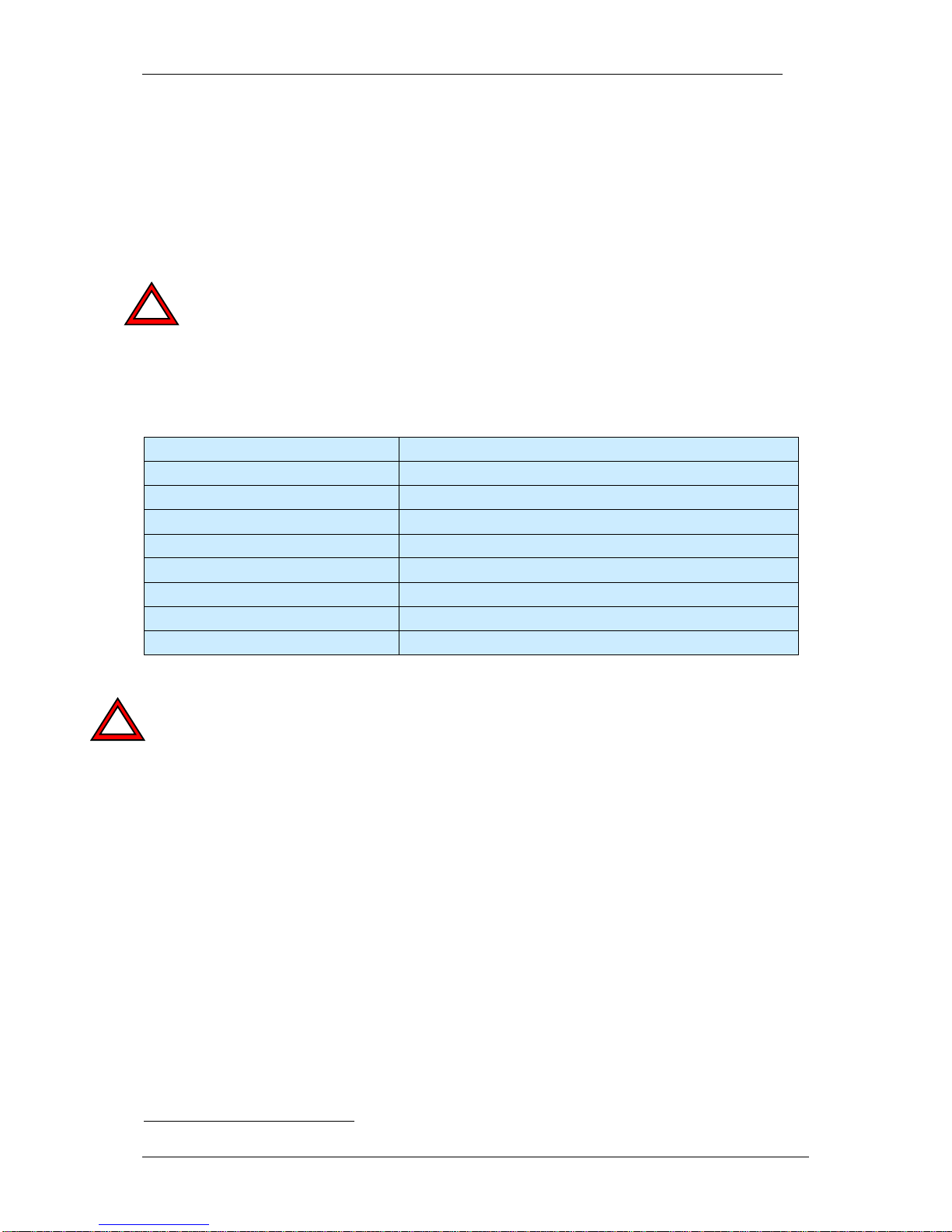
6.1.2 Available Accessories for LAN / Ethernet socket
Signal Pin (to cam.) Pin (to PC) Cable Color
20m patch cable
Cable Color
10m patch cable
T+ 2 1
yellow
white/pink
T- 1 2
orange
pink
R+ 6 3
white/green
white/green
R- 5 6
green
green
- 3 NC - - - 4
NC - -
Refer to section 7.2 for a list of available cables with order numbers.
Page 27

VC4XXX_HW.pdf – Hardware Documentation VC4XXX Smart Cameras
1996-2014 Vision Components GmbH Ettlingen, Germany
27
6.2 Trigger-/ V24- (RS232)-/ Keypad- / Encoder I nt er f a c e
The trigger interface now incorporates 4 different functions:
1. Image trigger input for hardware controlled image acquisition.
2. Incremental encoder interface (from July 2006 – cameras with S/N XX1XXXX).
3. Serial RS232 interface (can not be used at the same time as the encoder interface).
4. Keypad interface (uses the serial input of the serial interface).
Note the following important changes from the VC20XX series:
- The serial interface of the VC4XXX cameras now connects to the trigger interface – a new cable is
required and the pin allocation is different from VC20XX serial cameras.
- The “TrigIN –“ trigger input form the VC20XX has been omitted. The trigger input signal “TrigIN”
level now has to be 2.4 to 5V TTL relative to the trigger interface ground, pin 3. Existing trigger
circuits for VC20XX cameras have to be adjusted to the VC4XXX, or the camera may be
damaged. Sample circuits are provided in section 6.2.5.
- The trigger input is no longer opto-isolated – use own protection if required.
- The first VC40XX cameras had no integrated pull down resistor as shown in section 6.2.5. Since
the trigger input is floating in this case, provide own external pull up resistor or connect TTL push/
pull sensor.
- A new keypad is required – the VC20XX keypad is not compatible with VC4XXX cameras! Refer
to the “7.2” section for details.
Note the following important changes from the VC40XX cameras shipped until July 2006:
- New serial number for all VC4XXX with encoder input – XX1XXXX instead of XX0XXXX.
- New models now boot with serial output inactive to protect connected encoder. Refer to section 8
for information on enabling the serial input.
- The camera operating systems of both hardware versions are not compatible. Do not install an
incompatible OS, as the camera hardware might get damaged!
- The following table shows the last OS version for XX0XXX cameras and the first OS Version for
XX1XXXX cameras:
Camera
models
Latest VCRT Versions for XX0XXXX
cameras (without encoder interface)
First VCRT Versions for XX1XXXX
cameras (with encoder interface)
VC4038
VCRT 5.23
VCRT 5.24-8
VC4065
VCRT 5.24-3
VCRT 5.24-8
VC4066
VCRT 5.23
VCRT 5.24-8
VC4068 - VCRT 5.24-11
VC4466
VCRT 5.24-3
VCRT 5.24-8
VC4468 - VCRT 5.24-13
“VC Base Family” cameras VC4016 and VC4018 do not include an Encoder Interface.
VC4058, VC4438, VC4458, VC4465 and VC4472 all feature an Encoder Interface from the start.
Multiple use of the trigger interface:
A “Y” adaptor cable is available for connecting several components to the trigger interfac e – refer to
section 6.2.4 for details. The use of the serial input and the encoder interface is not possible at the
same time.
!
!
Page 28

VC4XXX_HW.pdf – Hardware Documentation VC4XXX Smart Cameras
1996-2014 Vision Components GmbH Ettlingen, Germany
28
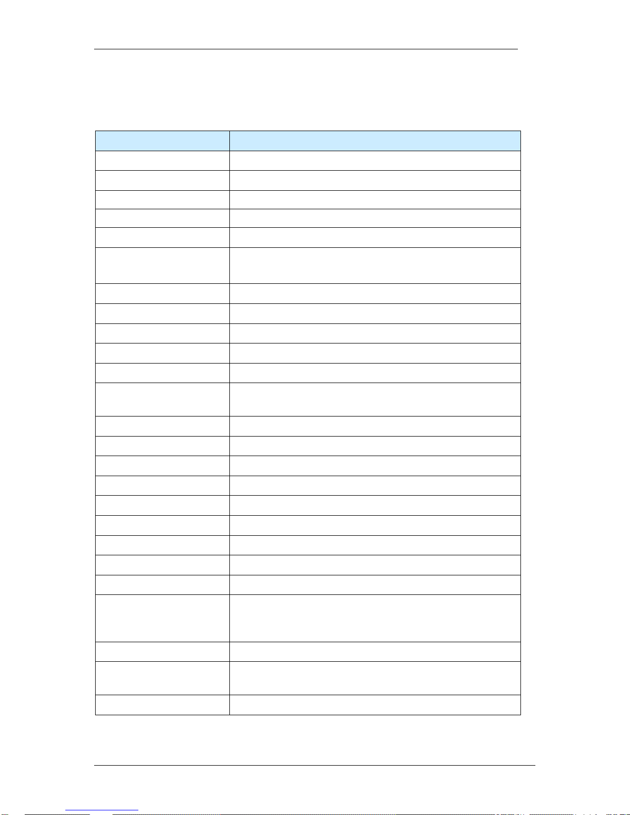
6.2.1 Pin Assignments Trigger-/ V24 (RS232)-/ Keypad/ - Encoder Interface
Pin Signals RS232 /
Standard Trigger
Signals Encoder Interface
Trigger
rear view camera socket:
1
V24 TxD Out
0+ (Zero Pulse Encoder)
6
1
3
4
5
2 + 5V Out + 5V Out (Power Supply TTL
Encoder)
3
GND
GND (Power Supply TTL Encoder)
4 V24 RxD In /
Keypad in
B+ (encoder input signal B+)
5
Trigger Out
Trigger Out
6
Trigger In
A+ (encoder input signal A+)
Compared with the VC20XX Trigger interface, the former “Trigin –“ Interface has been
replaced with a “V24 TxD Out” signal allowing the use of a bidirectional serial RS232 Interface
(refer to section 8 for programming details). This means when replacing a VC20XX camera
with a VC40XX the trigger input circuit needs to be modified, or the camera can be damaged!
See the Electrical specifications in secti on 6.2.5 for details.
Read the introduction of section 6.2 explaining important modifications of this interface
in order to avoid damaging the camera!
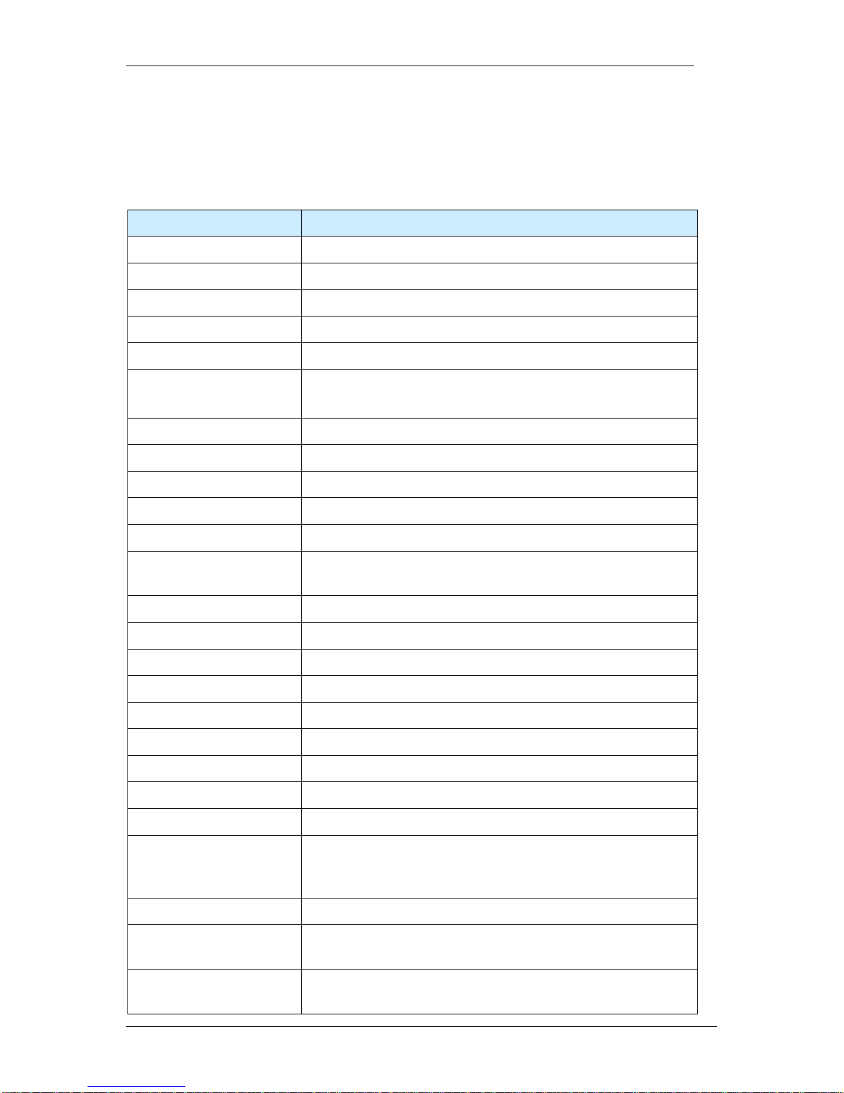
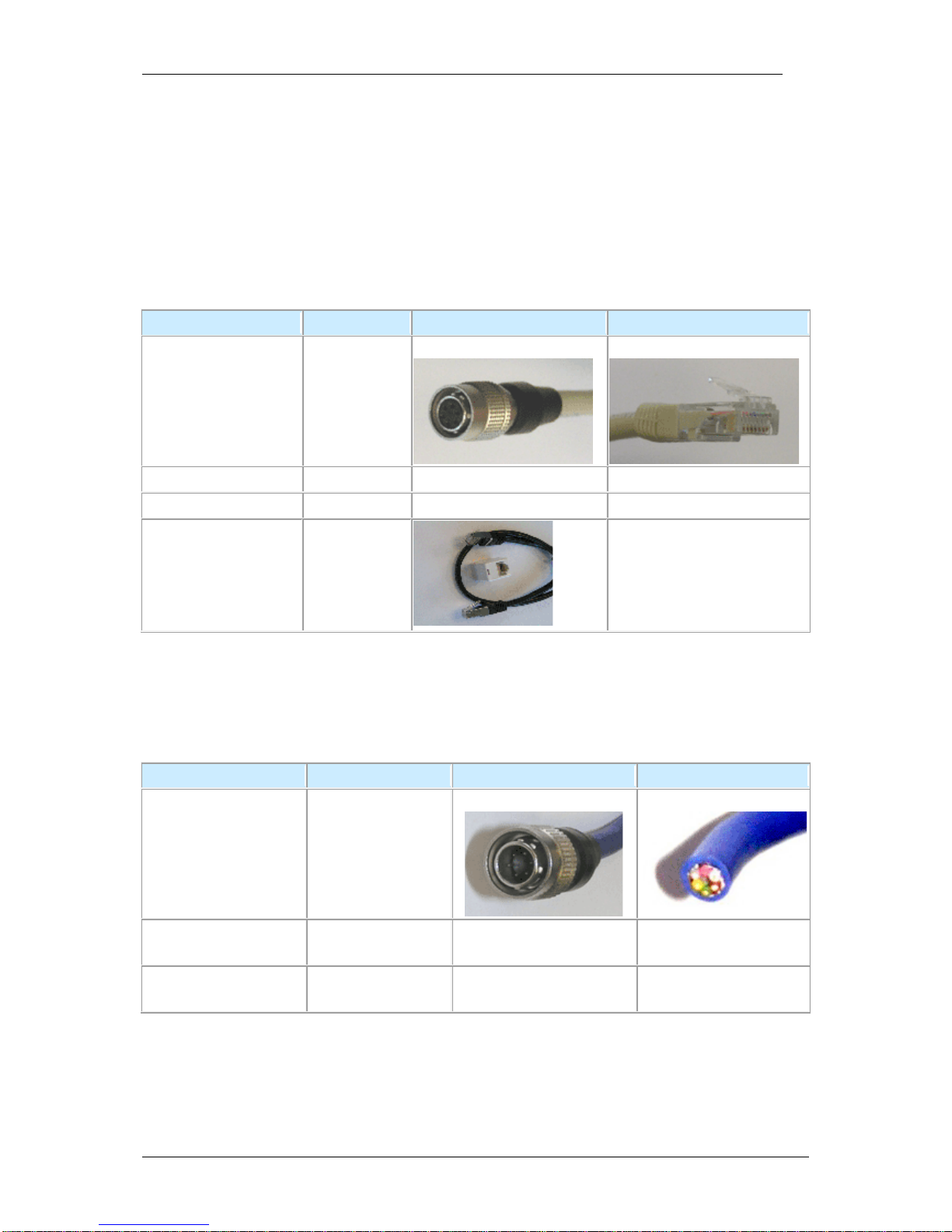
6.2.2 Trigger Cable
HIROSE 10A-7P-6SC
6-pin. solder plug
Length: 5m
Cable: 0.14mm LiYCY 6 conductors
shielded, outside diam eter 5 mm
2
Pin
Signal
Cable Color1
1
V24 TxD Out
green
2
+ 5V Out
brown
3 GND white
4
V24 RxD In
pink
5
Trigger Out
grey
6
Trigger In
yellow
Equipped on one end with a Hirose plug, length 5m, 10m or 25m
Refer to section 7.2 for a list of available cables with order numbers.
1
Note that the color coding for both cables has been chosen according to the VC20XX core colors.
For this reason the core colors of serial and trigger cables do not correspond to the same pin!
!
!
Page 29
VC4XXX_HW.pdf – Hardware Documentation VC4XXX Smart Cameras
1996-2014 Vision Components GmbH Ettlingen, Germany
29
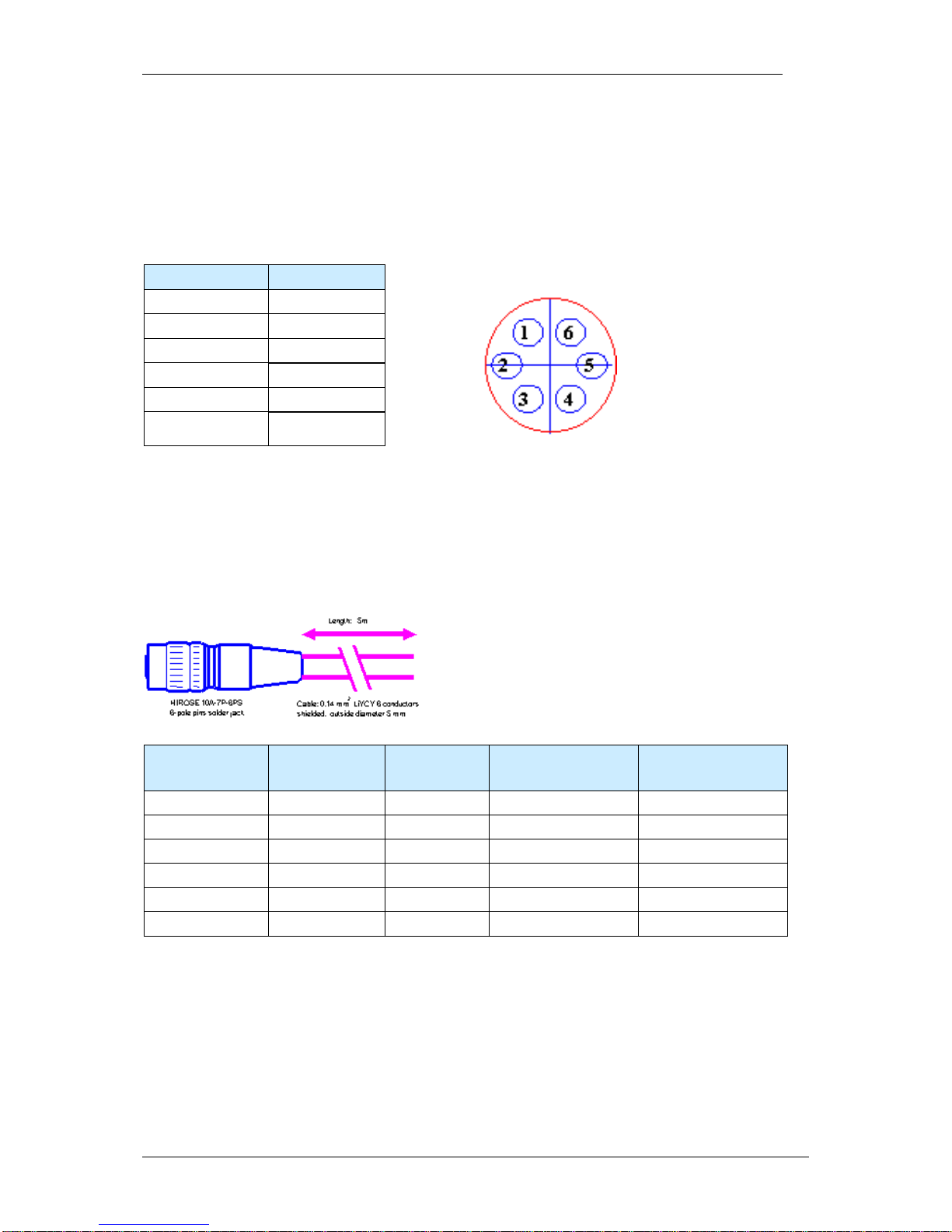
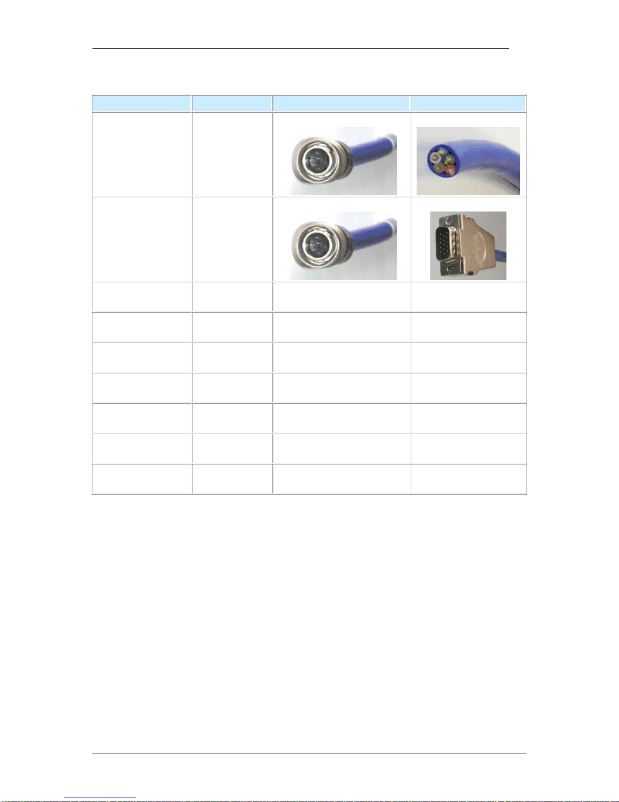
6.2.3 V24 (RS232) serial Cable
HIROSE 10A-7P-6SC
6-pin. solder plug
Length: 5m
Cable: 0.14mm LiYCY 6 conductors
shielded, outside diam eter 5 mm
2
Pin
Signal
Cable Color
1
V24 TxD Out
brown
2
+ 5V Out
pink
3
GND
grey
4
V24 RxD In
white
5
Trigger Out
NC
6
Trigger In
NC
Equipped on one end with a Hirose plug, length 5m, 10m or 25m and on the other end with a 9 pin Dsub connector. This cable can also be ordered with out the D-sub connector.
Refer to section 7.2 for a list of available cables with order numbers.
Refer to section 8.1 for information on programming the serial interface.
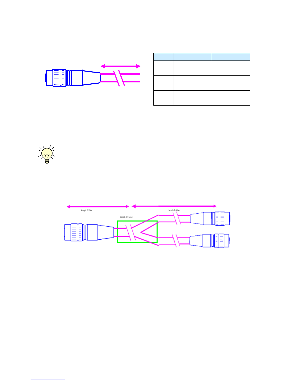
6.2.4 Y-Cable
Connectors:
1x HR10A-7P-6P, male connector
2x HR10A-7J-6S, female socket
Cable length: 0.5m
The color coding of this cable corresponds to the Trigger Cable described above.
All cables are connected through – from the camera output to both extension sockets. Beware of
possible undesired electrical contacts for instance when switching between encoder and serial input
and connecting both at the same time.
Refer to section 7.2 for a list of available cables with order numbers.
Page 30
VC4XXX_HW.pdf – Hardware Documentation VC4XXX Smart Cameras
1996-2014 Vision Components GmbH Ettlingen, Germany
30
6.2.5 Electrical Specifications of Trigger- / Serial-/ Keypad / Encoder Interface
The trigger interface features a dedicated fast TTL trigger input (for use as image capture trigger) and
a fast TTL trigger output (as strobe-light trigger). Since both signals are fast at a very low noise
margin, it is recommended to keep the cable as short as possible. Use shielded cable for this purpose.
Neither the trigger input nor the trigger output has an inbuilt-in photo coupler
2
. Please ensure
that the electrical specifications of this section are met and provide galvanic isolation to trigger
input and output if necessary.
Please note that input and output are not protected against over current. The output is neither
protected against short circuit nor reverse voltage spikes from inductive loads.
The trigger input assures constant delay without jitter.
Technical data of trigger input:
input voltage:
2.4 - 5 V (TTL, CMOS)
input current:
3mA @ 3V / 5mA @ 5V
limiting resistor:
none
pull down resistor 1 kΩ
Included in later models
Opto- isolation:
none
reverse voltage protection: none
switching delay:
Max. 2µsec + interrupt latency
Capture delay
Approx 40µsec (constant), for jitter free operation
Max encoder signal frequency
25 MHz
Note the modified circuit of the trigger input, due to the additional RS232 interface. Old trigger input
circuits need to be modified in order to prevent damaging the trigger input of the VC40XX camera. See
the introduction of section 6.2 for details. The use of a transistor in the trigger input circuit is
recommended as shown in the following figures. These are sample circuits only – please check the
final circuit layout as this depends largely on the sensor / equipment connected.
Please also note that the GND of the Trigger/ RS 232 i nterface is not identical with the Power Supply/
PLC GND, GND IN com. (refer to section 6.3).
Selection of a suitable TTL encoder for di re ct connection to the trigger interface
A suitable TTL encoder can be connected directly to the encoder interface. The encoder power supply
can be done using the 5V and GND outputs of the trigger interface. The 0+, A+, B+ encoder signals
can be connected according to section 6.2.1 An encoder with “push- pull” output characteristic can
save a pull down resistor on the trigger input (refer to “Encoder.pdf” – see References on page 2).
Do not exceed the current rating of 50 mA for the 5V o ut, pin 2 (k e ypad, enco der power supply).
The input voltage of the trigger input needs to be at least 2.4V (maximum Voltage: 5V).
Tested incremental encoder:
- 2420 range of miniature encoders, TTL, Ub = 5-24V, Signal Level = Ub -2.5V, push pull,
manufacturer: Kübler GmbH, www.kuebler.com
- Siemens 1XP8001-2, TTL, Ub = 5-10V, for 3 phase 220V asynchrone motor, size H58 Din 332
2
The VC Base Family camera range VC4018 and -16 incorporate opto coupler on trigger in and out.
!
!
Page 31

VC4XXX_HW.pdf – Hardware Documentation VC4XXX Smart Cameras
1996-2014 Vision Components GmbH Ettlingen, Germany
31
Suggested Trigger Input Circuit PNP
The 1kΩ internal pull down resistor is not included in the initial hardware release (delivery until end of
2005). Please provide external pull down resistor in case the trigger input stays high.
Suggested Trigger Input Circuit NPN
Trig In, Pin 6
GND, Pin 3
1kΩ
TTL Input
R
R
5V Out, Pin 2
Trig In, Pin 6
GND, Pin 3
1kΩ
TTL Input
Camera Circuit
Trigger Input Circuit
Camera Circuit
Trigger Input Circuit
5V Out, Pin 2
Page 32

VC4XXX_HW.pdf – Hardware Documentation VC4XXX Smart Cameras
1996-2014 Vision Components GmbH Ettlingen, Germany
32
Trigger Input Circuit compatible to VC20XX and VC40XX cameras:
The trigger input circuit shown above can be used to connect both – the VC20XX and VC40XX smart
camera families.
Technical data of trigger output:
output voltage:
max. 7V
output curent:
max. 50mA
pull-up resistor:
none, external resistor required
Note:
An external pull up resistor is required (for instance 1 kΩ) between Trig Out and 5V+ out in
order to pull the floating trigger output back to high.
The 100 Ω Resistor protecting the TTL trigger output Pin 5 from the VC20XX has been
replaced with a self resetting poly fuse (see the following drawing). The trigger output is
switching to ground (active low). The behavior of the output signal however can be
programmed high or low during exposure (see the “Programming Tutorial” or the “Trigin.c”
demo program).
5V Out, Pin 2 (VC20XX and VC40XX)
Trig In+, Pin 6 (VC20XX and VC40XX)
GND, Pin 3 (VC20XX and VC40XX)
Trig In - Pin 1 (VC20XX only!)
R
R
Camera Circuit
Trigger Input Circuit
R pull-up
Trig-Out
GND
External Circuit
!
Page 33

VC4XXX_HW.pdf – Hardware Documentation VC4XXX Smart Cameras
1996-2014 Vision Components GmbH Ettlingen, Germany
33
6.3 Power Supply and IO Interface
This connector includes the camera Power Supply and digital PLC IOs.
6.3.1 Pin assignments Power Supply and IO Interface
Pin
Signal
Calbe Colors
rear view camera socket:
1
12-24V PLC3
red
2
(12-4) 24V IN Cam
red / blue
3
GND IN com.
black.
4
INP 1
pink
5
OUT 3
yellow
6
OUT 2
green
7
OUT 1
brown
8
OUT 0
white
9
12-24V PLC3
grey / pink
10
INP 3
purple
11
INP 2
blue
12
INP 0
grey
6.3.2 Electrical specifications Camera Power Supply Camera
The power supply of the VC Base Family range differs form the VC Professional and VC Optimum
Smart Camera ranges. With the Professional and Optimum cameras it is possible to supply the PLC
outputs with a voltage different from the camera power supply via pin 1 and 9. For instance with the
VC4038 to VC4472 camera models it is possible to supply the PLC outputs with 12V via Pin 1 and Pin
9, if that is the required output voltage for OUT0 to OUT3.
With the VC4018 and VC4016 and VC4002L cameras these PLC supply contacts are
internally connected with the camera power supply pin 2. In this case pin 1 and 9 require the
same voltage level as the camera power supply pin 2. Refer to section 6.3.4 for details on the
different PLC interface features.
Power supply differences for VC Base – VC Professional and VC Optimum Family Smart Cameras:
VC Base Family Range (VC4016
and VC4018)
VC Professional and VC
Optimum Family Smart Cameras
Power Supply Voltage
12 V – 24 V 24 V
Absolute Voltage Limits
9 V -30 V 20 V – 28 V
PLC output power
supply separated from
camera supply
Camera power supply and
PLC output supply internally
connected!
PLC outputs supplied separately
via Pin 1 and Pin 9, common GND
of power supply and PLC outputs
3
The PLC output voltage equals the power supply voltage with VC4016 and VC4018 cameras.
4
VC Base Family cameras VC4018 and VC4016 only – all other cameras require 24V supply voltage.
!
Page 34

VC4XXX_HW.pdf – Hardware Documentation VC4XXX Smart Cameras
1996-2014 Vision Components GmbH Ettlingen, Germany
34
In general the camera power supply is regulated in the camera, so an unregulated power source is
sufficient. However the absolute voltage levels specified above – depending on the camera range should never be exeeded.
In case of unstable power supply (voltage spikes or power interruptions) it is recommended to backup
the power supply by a capacitor or a battery large enough to prevent power interruptions.
It isreccomended to switch on the low voltage supply (12 to 24V) when booting the camera. Some
110/ 220V power supplies increase the output voltage too slow or drop the voltage under load at start
– up which might cause the camera not to boot propperly!
6.3.3 Shutdown Function for VC Professional and VC Optimum
The VC Professional and VC Optimum Smart Cameras incorporate a circuit to detect and
protocol power failures. If the PLC output power supply (12-24V PLC, Pin 1 and 9) of the
VC4038 to VC4472 cameras is interrupted, the system variable “POWFAIL” is set to “1”. In
case the PLC outputs are supplied, the status of “POWFAIL” is “0” (refer to the sysvar.h).
This behaviour, that can also be checked using the shell command “ht”, can be used to perform a
controlled camera shutdown in case of a power failure.
Connecting the PLC/ Power interface for using this feature:
Signal
Pin No.
color
connect to
24V IN Cam 2 red/blue 24V backup supply (supplying power at least 100ms
longer than grid supply in case of a power failure)
24V PLC
1
red
24V standard power (grid) supply
24V PLC
9
grey/pink
24V standard power (grid) supply
GND IN com.
3
black
GND power supply
Here, the PLC voltage (24V PLC) is connected directly to the power (grid-) supply. The main camera
power supply at Pin 2 should remain high for at least 100ms longer than the power supplied to the
PLC supply. This can be done for instance with help of a suitable capacitor.
If a power failure occurs or if the main power supply is turned off, the camera detects this signal not
being present and the POWPLC status is changed from 0 to 1.
The system variable can be polled from time to time using the getvar(POWFAIL) function. This can be
best done using a background task.
The following procedures can be performed:
1. Stopping the operation of all programs and interrupts (no pictures will be taken any longer).
2. Saving all buffers (to multi-media card or flash EPROM).
3. Protocol time and date of the shutdown.
4. The procedure then waits for the backup voltage to disappear or main power to re-establish. If the
latter happens the program might be able to continue where it has stopped. (In this case there
may be some lost images = some parts not checked correctly)
This feature is only available for VC Professional and VC Optimum cameras (VC4038 to
4472).
Note that this feature is for emergency use only and is not designed to handle frequent
interruptions. The backup voltage must be able to supply the specified voltage for a period of
at least 100 msec (in addition to the polling delay).
!
Page 35

VC4XXX_HW.pdf – Hardware Documentation VC4XXX Smart Cameras
1996-2014 Vision Components GmbH Ettlingen, Germany
35
6.3.4 Electrical Specifications digital PLC IO Interface
The VC4XXX series Smart Camera features digital inputs and outputs that allow for instance direct
input of light barriers signals or the control of pneumatic valves.
Please observe the current and voltage ratings specified in the following sections.
The PLC circuit of all VC Professional and Optimum Smart Cameras is separated from the camera
power supply. This however is not the case with the VC Base Family range models VC4016 and
VC4018.
The different interface features for these camera ranges are shown in the following table.
PLC IO differences for VC Base Family- and the VC Professional and VC Optimum cameras:
VC Base Family Range
(VC4016 and VC4018)
VC Professional and VC Optimum
Smart Cameras
Separation of PLC
output voltage
PLC outputs supply not
separated from power supply
PLC output supply separated from
camera power supply (common GND)
PLC Input Voltage
Identical with power supply
voltage
12 V– 24 V
PLC Input Current (max)
1.5 mA at 12V to 3.5mA @ 24V 1.5 mA at 12V to 3.5mA @ 24V
PLC Output Voltage
Identical with power supply
Voltage – internally connected
12 V to 24 V - supplied separately via
pin 1 and pin 9.
PLC Output Current
(max)
4 x 400 mA
Max total all outputs: 1A
4 x 500 mA
Max total all outputs: 1A
Max Current for 1 Power
/ PLC connector pin
500 mA 500 mA
Power failure detection
- see section 6.3.3
While the PLC outputs of the VC Professional and VC Optimum Families can be supplied with a
voltage different from the camera supply voltage, this is not the case with the VC Base Family
cameras, as mentioned above.
Irrespective of the camera model – when using the PLC outputs connect both PLC output
supply pins (pin 1 and pin 9) in order to limit the connector pin current.
The maximum combined current of all outputs should not exceed 1 A.
6.8k
1k
PLCin
max 24V
+20%
GNDin com
!
!
Page 36

VC4XXX_HW.pdf – Hardware Documentation VC4XXX Smart Cameras
1996-2014 Vision Components GmbH Ettlingen, Germany
36
6.3.4.1 Connection of Inputs VC Professional and VC Optimu m F amily
12 24V
inside camera
external switch,
relais, PLC, light
barrier, etc.
GND
(black cable)
+
- 4 digital Inputs
- Operating Voltage 12 to 24 V
- Threshold Voltage 8V (input high for signals
greater 8V)
- Maximum Voltage: 28V
- Reverse voltage protection
- Input Current 1mA @ 24V
- Signal debouncing hardware: 2.5 μs
(signals up to 2.5 μs length are ignored)
- Signal Debouncing Software: 40 μs waiting
time until a signal change is acknowledged
6.3.4.2 Connection of Outputs VC Professional and VC Optimum Family
relais,
motor,
etc.
GND
(black cable)
12-24V
(red cable)
inside camera
12-24V
+
- 4 digital outputs
- Operating Voltage 12 to 24 V
- current per output: 500 mA (total
current all outputs < 1000 mA)
- Connect both 12-24 V PLC power
supply pins 1 and 9.
- bit = 1 output will switch positive
voltage
- short-circuit and over- temperature
protection (2A)
6.3.5 Available Accessories / Cables for Power Supply and IO Interface
Equipped on one end with a Hirose plug jack, length 5m, 10m or 25m
Refer to section 7.2 for a list of available cables with order numbers.
Page 37

VC4XXX_HW.pdf – Hardware Documentation VC4XXX Smart Cameras
1996-2014 Vision Components GmbH Ettlingen, Germany
37
6.4 Video Output Interface
6.4.1 Pin Assignment of Video Output Interface
6.4.2 Available Accessories / Cables for Video Output Interface
HIROSE 10A-10P-10P
10-pin. pins solder plug
Length: 5m
Cable: 5 x mini coaxial cabl e 75 Ohm
outside diameter 7 mm
Signal
Pin No.
Connection
R Out
4
red signal
R GND
3
red shield
G Out
2
green signal
G GND
1
green shield
B Out
9
blue signal
B GND
8
blue shield
HS Out
10
white signal
HS GND
7
white shield
VS Out
6
gray signal
Equipped on one end with a Hirose plug, length 5m , 10m and 25m.
Please order "with 2nd connector", if you need a DSUB15 connector at the other end.
Refer to section 7.2 for a list of available cables with order numbers. The video interface is not
available for the VC Base Family cameras VC4016 and VC4018.
Pin
Signal
rear view camera socket:
1
G GND
2
G Out
3
R GND
4
R Out
5
VS GND
6
VS Out
7
HS GND
8
B GND
9
B Out
10
HS Out
Page 38

VC4XXX_HW.pdf – Hardware Documentation VC4XXX Smart Cameras
1996-2014 Vision Components GmbH Ettlingen, Germany
38
7 Order Numbers Cameras and Accessories
7.1 Order numbers of all available VC4XXX Camera Models:
7.1.1 Order Numbers “VC Base” Models:
Article Description
Order Number
VC4018
VK000258
VC4018C
VK000267
VC4016
VK000257
VC4016C
VK000268
7.1.2 Order Numbers “VC Professional” Models:
Article Description
Order Number
VC4038
VK000230
VC4058
VK000303
VC4065
VK000249
VC4066
VK000250
VC4067
VK000361
VC4067 NIR
VK000423
VC4068
VK000269
7.1.3 Order Numbers “VC Optimum” Models:
Article Description
Order Number
VC4438
VK000333
VC4458
VK000304
VC4459
VK002090
VC4465
VK000301
VC4465C
VK000302
VC4466
VK000272
VC4467
VK000360
VC4467 NIR
VK000427
VC4468
VK000300
VC4472
VK000307
Page 39
VC4XXX_HW.pdf – Hardware Documentation VC4XXX Smart Cameras
1996-2014 Vision Components GmbH Ettlingen, Germany
39
7.2 Order numbers of all available VC4XXX Accessories
For interface cables and connectors available also consult the corresponding section in chapter 6 of
this manual as well as the “VC Smart Camera Accessories” section – under the “Product” section on
our website www.visoin-comp.com .
Ethernet Cables (Refer to section 6.1.2):
Article Description
Order Number
Camera Connector
Second Connector
5m LAN-C6-Cable
VK000149
HRS connector female 6 pin RJ45
10m LAN-C6-Cable
VK000150
HRS connector female 6 pin
RJ45
20m LAN-C6-Cable
VK000151
HRS connector female 6 pin
RJ45
Ethernet Cross Module
VK000156
RJ45
RJ45 female socket
Trigger Cables (Refer to section 6.2.2):
Article Description
Order Number
Camera Connector
Second Connector
5m Trigger-Cable / C6 VK000115
HRS connector male 6 pin
without connector
10m Trigger-Cable / C6
VK000164
HRS connector male 6 pin
without connector
25m Trigger-Cable / C6
VK000153
HRS connector male 6 pin
without connector
Page 40

VC4XXX_HW.pdf – Hardware Documentation VC4XXX Smart Cameras
1996-2014 Vision Components GmbH Ettlingen, Germany
40
V24 (RS232) Serial Cable (Refer to section 6.2.3):
These cables differ from the serial VC20XX C6 cables!
Article Description
Order Number
Camera Connector
Second Connector
5m V24 cable VK000243
HRS male 6 pin
without connector
5m V24 cable with DSUB VK000244
HRS male 6 pin
D-SUB 9 pin female
10m V24 cable
VK000239
HRS male 6 pin
without connector
10m V24 cable with DSUB
VK000240
HRS male 6 pin
D-SUB 9 pin female
25m V24 cable
VK000241
HRS male 6 pin
without connector
25m V24 cable with DSUB
VK000242
HRS male 6 pin
D-SUB 9 pin female
Y-Cable for connecting several cables to the Trigger / Serial Interface (Refer to section 6.2.4):
Article Description
Order Number
Camera Connector
Second Connector
0.5m Y adapter cable VK000124
HRS male 6 pin
2 HRS female 6 pin
Power Supply and IO Interface Cables (refer to section 6.3.5):
Article Description
Order Number
Camera Connector
Second Connector
5m Power / PLC-Cable C6 VK000008
HRS female 12 pin
without connector
10m Power / PLC-Cable C6
VK000114
HRS female 12 pin
without connector
25m Power / PLC-Cable C6
VK000161
HRS female 12 pin
without connector
!
Page 41
VC4XXX_HW.pdf – Hardware Documentation VC4XXX Smart Cameras
1996-2014 Vision Components GmbH Ettlingen, Germany
41
VGA Video Output Cable (refer to section 6.4.2):
Article Description
Order Number
Camera Connector
Second Connector
5m SVGA-cable VK000006
HRS connector male 10 pin
without connector
5m SVGA-cable with
DSUB
VK000083
HRS connector male 10 pin
HD-SUB 15 pin male
5m SVGA-cable with
DSUB
VK000079
HRS connector male 10 pin HD-SUB 15 pin female
10m SVGA-cable VK000061
HRS connector male 10 pin
without connector
10m SVGA-cable with
DSUB
VK000133
HRS connector male 10 pin
HD-SUB 15 pin male
10m SVGA-cable with
DSUB
VK000080
HRS connector male 10 pin HD-SUB 15 pin female
25m SVGA-cable VK000065
HRS connector male 10 pin
without connector
25m SVGA-cable with
DSUB
VK000098
HRS connector male 10 pin
HD-SUB 15 pin male
25m SVGA-cable with
DSUB
VK000082
HRS connector male 10 pin HD-SUB 15 pin female
Page 42

VC4XXX_HW.pdf – Hardware Documentation VC4XXX Smart Cameras
1996-2014 Vision Components GmbH Ettlingen, Germany
42
Further Accessories:
Article Description
Order
Number
Camera Connector
Power Adapter C6 24V, with 12 pins conn. 3m VK000119
HRS connector female 12 pin
Power adapter for rail mounting, Input Voltage
100 - 240VAC 50/60 Hz, Output Voltage DC
24V +/-5%, max. 300 mA (7.5 W),
Equipped with connecting clamps for AC input
and 24V output, CE cert.
Using this power supply with VC Base
Cameras (VC4018 and VC4016) is only
possible when booting by switching the 24V
secondary side! 15W power supply needed
if switching the mains supply!
VK000036
VCSKBC4 Keypad (different from VCSKBC6
for VC20XX cameras!)
VK000238
IR cut filter (camera is shipped with this filter
mounted) refer to Appendix E
EK000625
Clear glass filter (replaces IR Cut filter)
EK000628
IR Transmitting Filter
EK000624
Flex cables for detached Camera Head mounting:
30mm length,20 core
5
EK000321
80 mm length,20 core 5
EK000322
200 mm length,20 core 5
EK000629
5
The feasibility of remote head mounting depends on working conditions (electrical noise, electro
magnetic radiation emitted from the camera, voltage drop over sensor cable, etc.). VC’s CE
certification is valid only for the standard camera set up.
!
Page 43
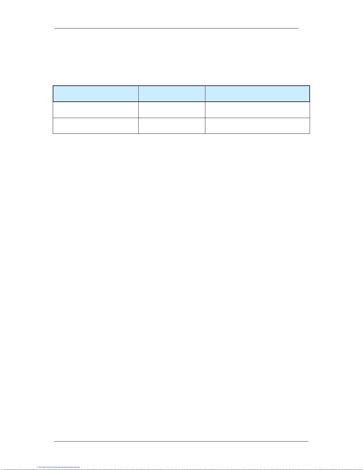
VC4XXX_HW.pdf – Hardware Documentation VC4XXX Smart Cameras
1996-2014 Vision Components GmbH Ettlingen, Germany
43
8 Programming VC4XXX Smart Cameras
This section contains special programming features for the VC4XXX smart camera series. Standard
software functions are described in following manuals:
Type of resource Name of file Download location
www.vision-comp.com
SW manual OS functions VCRT5.pdf
Service&Support Download Center
Documentation
SW manual Image Processing
Functions
VCLIB_300.pdf
Service&Support Download Center
Documentation
Please also check the “Getting Started VC” (Schnellstart VC Smart Kameras) as well as the “Support
News” and the “Knowledge Base / FAQ” on our website (see the “References” section on the very first
Page of this manual).
8.1 Programming the additional Serial Interface
The following program shows the programming of the VC4XXX serial interface (refer to section 6.2):
With the new encoder interface, it is required to initialize the serial interface prior to its use with the
following macro:
INTERFACE_MODE(SERIAL);
void sertest(void)
{
FILE *tty;
//unsigned xbaud=115200;
unsigned xbaud=9600;
char c=0;
print("\nSerial Interface Test press <ESC> to abort\n\n");
INTERFACE_MODE(SERIAL);
tty = fopen("kbd:", (void *)0); /* open serial device */
print("Set baudrate=%d\n",xbaud);
io_ioctl(tty,IO_IOCTL_SERIAL_SET_BAUD,&xbaud);
xbaud=0;
io_ioctl(tty,IO_IOCTL_SERIAL_SET_FLAGS,&xbaud);
print("\nWriting 'abcdefg' to serial device !\n");
write(tty,"abcdefg",7);
print("\nAny typed char on serial device will be echoed!\n");
print("\nPress ESC on serial terminal to exit!\n");
while(c != 0x1b && rbempty()==-1)
{
if(io_fstatus(tty)) // test if there are some chars in in buffer
{
c=io_fgetc(tty);
print("c=0x%x\n",c);
Page 44

VC4XXX_HW.pdf – Hardware Documentation VC4XXX Smart Cameras
1996-2014 Vision Components GmbH Ettlingen, Germany
44
if(c!=0x1b)
{
{
io_fputc(c, tty);
}
}
}
}
fclose(tty); /* close serial device */
fclose(tty); /* close RS485 */
}
8.2 Programming the Encoder Interface
Refer to section 6.2 for details on this interface and also the separate “Encoder Application Notes” under
“References” on page 2 of this document!
The encoder interface needs to be enabled prior to its use:
INTERFACE_MODE(ENCODER); // Encoder mode (RS232 disabled)
void enctest(void)
{
int Run=1,i=0;
char c;
print("\nEncoder Interface Test, press <ESC> to abort\n\n");
TRIGINP_NEG() ; // turning direction anti clockwise
tpict(); // take image to end live mode
INTERFACE_MODE(ENCODER); // Encoder mode (RS232 disabled)
ENC_DISABLE_CNT(); // disable counter
//ENC_WAIT_N(); // wait one time for next 0+ pulse
ENC_WAIT_N_TRIG(); // wait every time for next 0+ pulse
ENC_ENABLE_CNT(); // enable inputs
ENC_WRITE_CNT(506); // set Counter value
ENC_WRITE_RELOAD(256); // set Reload value
while(Run)
{
tenable(); // wait for external trigger and take picture
while(!trdy()) // wait for image completion
{
if(kbhit()) // check for keyboard input
{
c=rs232rcv();
if(c==0x1B) // check for "ESC"
{
while(cancel_capture_rq());
Run = 0; // deleting last capture request
}
}
printf("encodervalue is: %08d \r",ENC_READ_CNT());
wait(0,50); // waiting time to slow printing
}
print("************* exposure ************** (%u)\n",i++);
}
INTERFACE_MODE(SERIAL); // Serial mode (RS232 enabled)
vmode(0); // swtiching camera back to live mode
}
Page 45

VC4XXX_HW.pdf – Hardware Documentation VC4XXX Smart Cameras
1996-2014 Vision Components GmbH Ettlingen, Germany
A
Appendix A: Block diagram VC40XX Smart Cameras
Appendix B: Block diagram VC4018/ -16 Smart Cameras
CCD -
Sensor
PGA
CDS
A/D Con-
verter
FIFO
Trigger In/
Out
Control/
Stat us Reg.
PLC
Interface
32 MB SDRAM
4 MB Flash
Eprom
TMS
C64XX
DSP
Bus Controller
Driver
Controller
MODE
UART
(Receiver)
Trigger In/ Out
24V PLC In/ Out
Ethernet
Page 46

VC4XXX_HW.pdf – Hardware Documentation VC4XXX Smart Cameras
1996-2014 Vision Components GmbH Ettlingen, Germany
B
Appendix C: Dimensions VC Base (VC4018 and VC4016)
Maximal torque for M6 screws (all camera models) : 10 Nm
Appendix D: Dimensions VC Professional and VC
Optimum models
!
Page 47

VC4XXX_HW.pdf – Hardware Documentation VC4XXX Smart Cameras
1996-2014 Vision Components GmbH Ettlingen, Germany
C
Appendix E: Drawing Camera Head VC40XX and VC44XX
Page 48

VC4XXX_HW.pdf – Hardware Documentation VC4XXX Smart Cameras
1996-2014 Vision Components GmbH Ettlingen, Germany
D
Appendix F: Spectral Transmission of IR Filter
Note:
This IR cut filter is incorporated in every VC40XX camera. The IR filter can be removed if
required without loosing Vision Component’s manufacturer’s warranty. In this case, special
care must be taken not to damage the CCD sensor.
If the camera is used without IR filter it is important to replace it by a clear glass filter of the
same size. The C-mount flange distance from the CCD is accurately adjusted for the use of
the IR filter – removing the filter decreases the length of the optical path and it may become
impossible to focus some lenses to a larger working distance.
If the IR filter is not to be used, please order your camera with a clear glass filter or contact
Vision Components for obtaining a glass filter.
The order numbers for the clear glass filter is: EK000624
The order number for the IR cut filter (standard) is: EK000625
!
Page 49

Visit the Vision Components site www.vision-components.com for further information,
documentation and software downloads:
Web Site Menu Links Content
Home
Latest News from VC
Competences
VC Company Information
VC Network
Solutions
Applications
Industry
Products
VC Smart Cameras
Product Overview:
VC Base
VC Professional
VC Optimum
VC Line
Visicube
VC Board Cameras
VC Customized
Accessories
VC Smart Camera Software
VC Software Development Kit Ti: VCRT Operating System
VCLIB Image Processing Library
VC Special Libraries: Color Lib
Extension Lib
VCOCR Text Recognition Library
VC Smart Reader
VC Smart Finder
VC Solar Solution
News and Events
VC News
Trade Show dates
VC Seminars & Workshops
Service & Support:
Contact Contact Vision Components
Download Center Download of:
Documentation
(User Registration required)
- Product Brochures
- Camera Manuals
-
Getting Started
- Programming Manuals
- Training Manuals and Demo Code
Software
(User- and SW License
Registration required)
- Software Updates (VCRT & Libs)
- Demo Code
- Software utilities
Tech News
Tech News – new SW and Documentation
Knowledge Base / FAQ FAQ Database with programming Examples and
Demo Code
Return / Repair Service
Form for Allocation of Repair Numbers.
Loan systems
Info about VC loan cameras
 Loading...