

Page 1
Vision
Components
®
The Smart Camera People
VC20XX Operating Manual
Hardware Specifications and special Software Functions of
VC20XX Smart Cameras
Revision 2.2 October 2007
Document name: VC20XX_HW.pdf
© Vision Components GmbH Ettlingen,
Germany
Page 2
VC20XX Operating Manual
II
Foreword and Disclaimer
This documentation has been prepared with most possible care. However Vision Components GmbH
does not take any liability for possible errors. In the interest of progress, Vision Components GmbH
reserves the right to perform technical changes without further notice.
Please notify
support@vision-components.com if you become aware of any errors in this manual or
if a certain topic requires more detailed documentation.
This manual is intended for information of Vision Component’s customers only. Any publication of this
document or parts thereof requires written permission by Vision Components GmbH.
Trademarks
Code Composer Studio and TMS320C6000, Windows XP, Total Commander, Tera Term, Motorola
are registered Trademarks. All trademarks are the property of their respective owners.
References
Since the VC4XXX smart camera family employs a TI processor, the programming environment and
functions for the VC20XX cameras can be used for this camera.
Further References under “Support + Download” on
www.vision-components.com:
„Support News“ – for up to date information on VC Software and Documentation.
„
Knowledge Base / FAQ“ - searchable Database with latest software developments, frequently asked
questions and demo programs.
“
Download Areas” for all documentation and Software downloads – refer to the following table:
Description Title on Website Download Area
Schnellstart VC .
Schnellstart VC Smart
Kameras
Registered User Area
Getting Started VC SDK TI
Getting Started VC Smart Cameras
.
Getting Started VC Smart
Cameras
Registered User Area
Getting Started VC SDK TI
Introduction to VC Smart Camera
programming
Programming Tutorial for
VC20XX and VC40XX Cameras
Registered User Area
Getting Started VC SDK TI
Demo programs and sample code
used in the Programming Tutorial
Tutorial_Code
Registered User Area
Getting Started VC SDK TI
VC4XXX Hardware Manual
VC4XXX Smart Cameras
Hardware Documentation
Public Download Area Hardware
Documentation VC Smart Cameras
VCRT Operation System Functions
Manual
VCRT 5.0 Software Manual
Registered User Area Software
documentation VC Smart Cameras
VCRT Operation System TCP/IP
Functions Manual
VCRT 5.0 TCP/IP Manual
Registered User Area Software
documentation VC Smart Cameras
VCLIB 2.0 /3.0 Image Processing
Library Manual
VCLIB 2.0/ 3.0 Software
Manual
Registered User Area Software
documentation VC Smart Cameras
The Light bulb highlights hints and ideas that may be helpful for a development.
This warning sign alerts of possible pitfalls to avoid. Please pay careful attention to sections
marked with this sign.
!
Author: Peter Neuhaus, VC Support,
mailto:support@vision-comp.com
© 1996-2007 Vision Components GmbH Ettlingen, Germany VC20XX_HW.pdf
Page 3

VC20XX Operating Manual
III
Table of Contents
1 General Information 1
1.1 Overview Camera Types 2
2 Basic Structure 4
3 Boards 5
3.1 Sensor Boards 5
3.1.1 C6SEN084 6
3.1.2 C6SEN204 6
3.1.3 C6SEN205 7
3.1.4 C6SEN311 7
3.1.5 C6SEN415 8
3.2 CPU Board 8
3.3 DAC Board 9
3.4 Power Board 10
4 PLC I/O Signals 11
4.1 Input Signals 11
4.2 Output Signals 12
4.3 Trigger input and trigger output 12
5 Pin Assignments Camera Interfaces 14
5.1 Pin Assignment Trigger / Keypad Plug Signal 14
5.2 Pin Assignment for the I/O Plug 14
5.3 Pin Assignment for the RS232 (V24) 15
5.4 Pin Assignment LAN/Ethernet 15
5.5 Pin Assignment for the XGA/SVGA Video Output 15
6 Technical Specifications VC20XX Smart Cameras 16
6.1 Technical Specifications VC2028 16
6.2 Technical Specifications VC2038 17
6.3 Technical Specifications VC2038/E 18
6.4 Technical Specifications VC2048/E 19
6.5 Technical Specifications VC2065 20
6.6 Technical Specifications VC2065/C 21
6.7 Technical Specifications VC2065/E 22
6.8 Technical Specifications VC2065/EC 23
6.9 Technical Specifications VC2066 24
6.10 Technical Specifications VC2066/E 25
6.11 Technical Specifications VC2068 26
6.12 Technical Specifications VC2068/E 27
7 Accessories 28
7.1 Trigger Cable 28
7.2 RS232(V24) Cable 28
© 1996-2007 Vision Components GmbH Ettlingen, Germany VC20XX_HW.pdf
Page 4

VC20XX Operating Manual
IV
7.3
Ethernet patch cable 29
7.4 Power / PLC Cable 29
7.5 SVGA Monitor Cable 29
7.6 Power adapter 30
7.7 Power adapter for rail mounting 30
7.8 VC Keypad C6 30
7.9 Y-cable 30
8 Connecting the Camera 31
8.1 Connecting the camera power 31
8.1.1 Single voltage, with or without PLC signals, no shutdown: 31
8.1.2 Shutdown Function for VC20XX Smart Cameras 32
8.2 Connecting the RS232 Interface 33
8.2.1 Connecting a compatible PC with a 9-pin D sub plug 33
8.3 Connecting the Ethernet Cable 33
8.4 Connecting the VC keypad 33
8.5 Connecting the external trigger 34
8.6 Connecting the external trigger and the VC keypad 34
9 Programming 35
Appendix A: Blockdiagram VC20XX Smart Cameras A
Appendix B: Housing Dimensions VC20XX Smart Cameras B
Appendix E: Drawing Camera Head VC40XX C
Appendix C: Spectral Transmission of IR Filter D
Appendix D: CE Compliance of VC20XX Smart Cameras E
INDEX G
© 1996-2007 Vision Components GmbH Ettlingen, Germany VC20XX_HW.pdf
Page 5
VC20XX Operating Manual
1
1 General Information
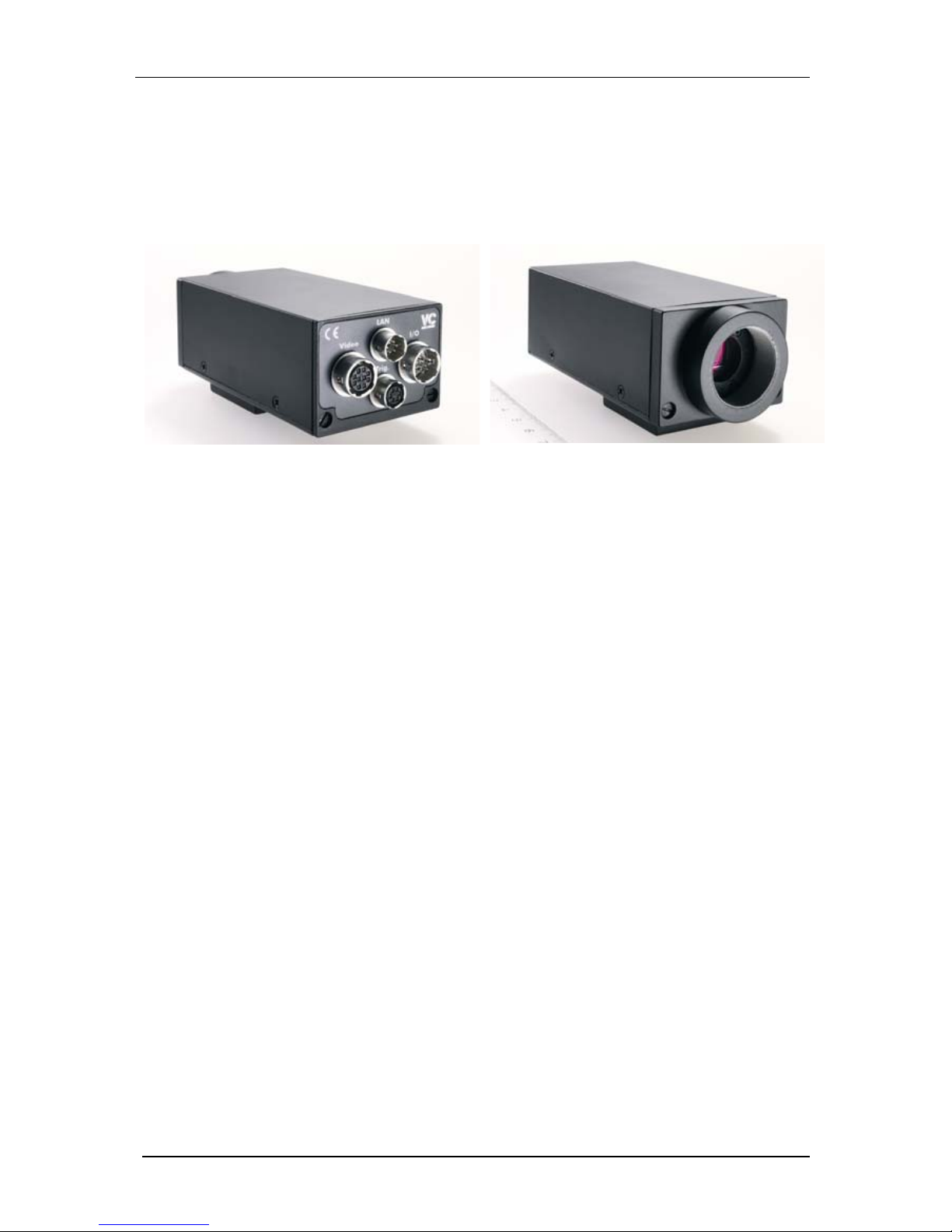
The VC20xx Series smart cameras are compact, light-weight black-and-white or color video cameras
with video memory and an image processor.
They integrate a high-resolution CCD sensor with one of the fastest 32 bit image-processing signal
processors (TMS320C6211). SDRAM memory is used to store program code, data and video images.
Interfaces allow communication with the outside world. The cameras set standards for performance
and integration density.
These cameras are built for industrial deployment. High goals were set as regards the image
resolution, the computational speed, the sturdiness of the casing, and the electromagnetic
compatibility, as mere examples. The cameras are insensitive to vibrations and shocks, while
permitting precise measurements and tests. They are ideally suited as OEM cameras for mechanical
engineering applications.
Only one supply voltage is required to operate the cameras (24 volts). An image processing system or
a PC with a frame grabber board is not necessary. Simple control problems can even be implemented
with the integrated process interfaces. For more complex control tasks, the cameras can be connected
to a PLC.
This documentation describes the camera hardware. However, in many cases the software
documentation is decisive. For this, please consult the software manuals.
© 1996-2007 Vision Components GmbH Ettlingen, Germany VC20XX_HW.pdf
Page 6
VC20XX Operating Manual
2
1.1 Overview Camera Types
All VC20XX Cameras contain the following features:
- 16 MB SDRAM
- 2 MB Flash Eprom
- 8 bit overlay (translucent overlay possible)
- integrated 4 Digital Inputs, 4 Digital Outputs, 24V
- Texas Instruments CPU TMS 320C62XX; 1200MIPS
- Low speed shutter up to 10 seconds
- Programmable gain and offset
- 24V Power Supply
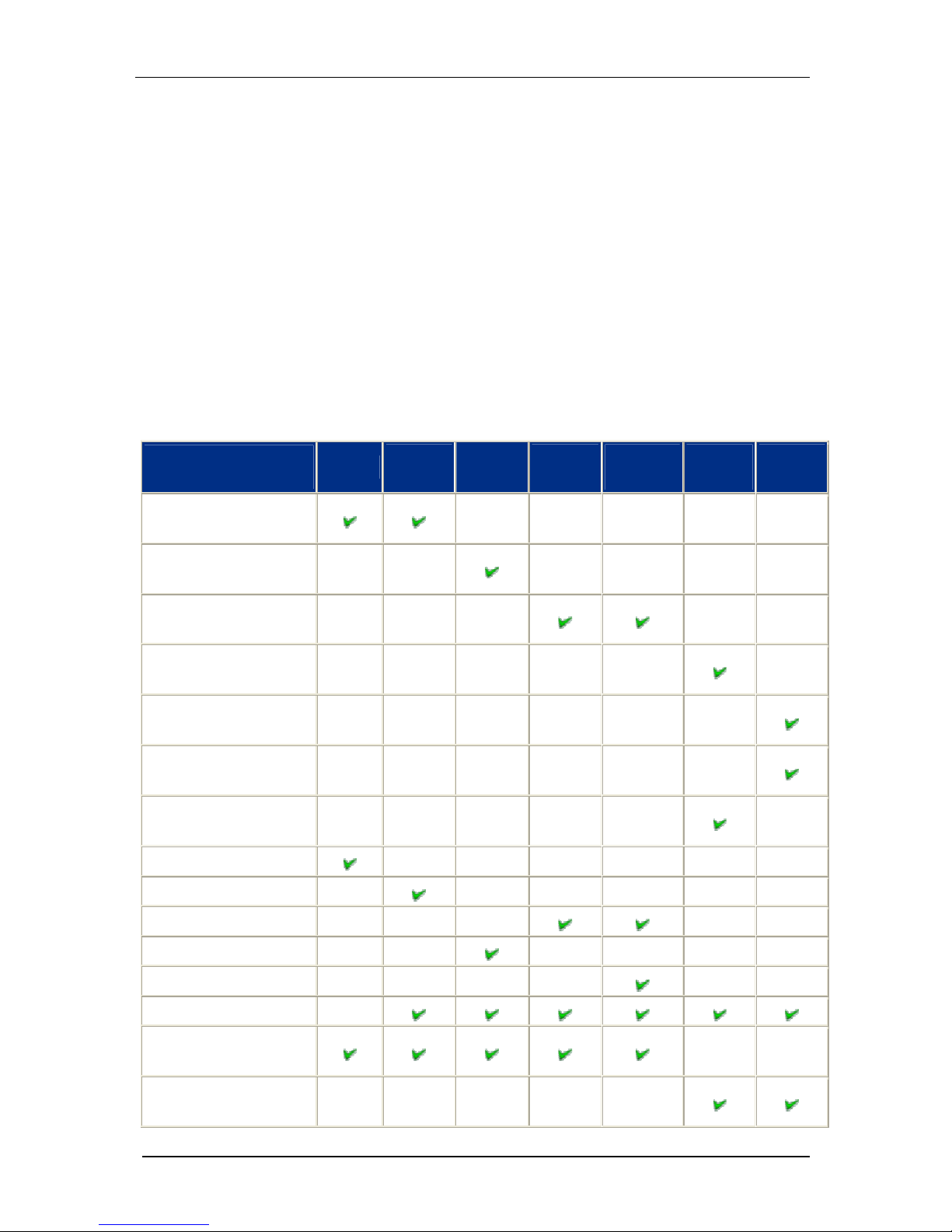
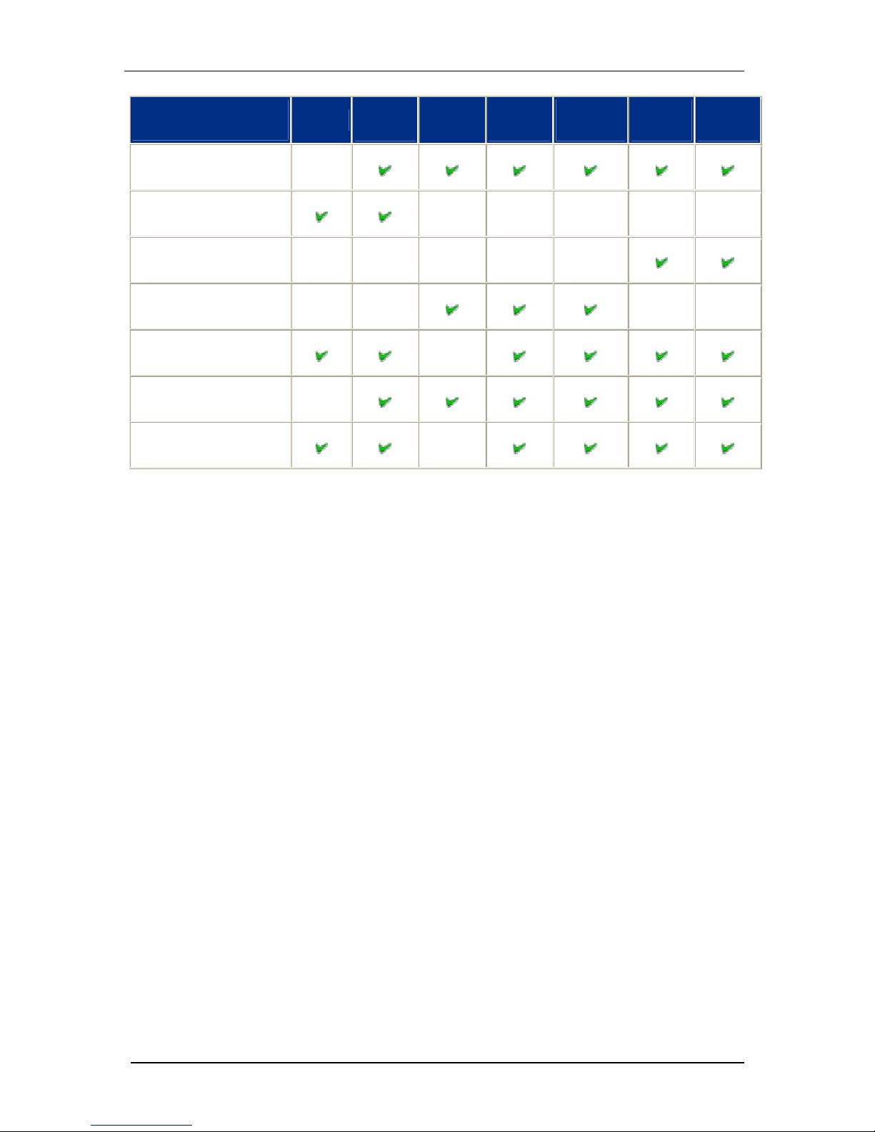
The following table shows the different features of each camera model:
VC20XX SELECTION
TABLE
VC2028
VC2038
VC2038E
VC2048E
VC2065
VC2065E
V2065C
VC2065CE
VC2066
VC2066E
VC2068
VC2068E
Sony 1/3" Progressive Scan
CCD640x480 pixel
Kodak 1/3" Progressive
Scan CCD 640x480 pixel
Sony 1/2" Progressive Scan
CCD 782x582 pixel
Sony 1/3" Progressive Scan
CCD 1024x768 pixel
Sony 1/2" Progressive Scan
CCD 1280x1024 pixel
14 Hz full Frame, 28 Hz 2x
Binning
17 Hz full Frame, 34 Hz 2x
Binning
25 Hz full Frame
40 Hz full Frame
45 Hz full Frame
110 Hz full Frame
Color
16 MB Multimedia Card
SVGA (800x600 Pixel)
output, noninterlaced
SXVGA (1280x1024 Pixel)
output, noninterlaced
© 1996-2007 Vision Components GmbH Ettlingen, Germany VC20XX_HW.pdf
Page 7
VC20XX Operating Manual
3
VC20XX SELECTION
TABLE
VC2028
VC2038
VC2038E
VC2048E
VC2065
VC2065E
V2065C
VC2065CE
VC2066
VC2066E
VC2068
VC2068E
integrated Fast Trigger
contact (external contact)
1)
High speed shutter down to
33 microseconds
High speed shutter down to
9 or 10 microseconds
High speed shutter down to
5 microseconds
RS232 up to 115.200 Baud
(optional)
Fast Ethernet 100MBit
(optional) 2)
Size: 110x50x36mm+foot/
Weight: 488g
3)
1) The use of the VC2028 is recommended for imaging static (non moving) objects only.
2) If ordering a camera with Ethernet interface please add the suffix "/E" to the camera name (i.e.
VC38/E, VC2065/EC).
3) Dimension of housing VC2048: 111x80x36 + mounting plate, weight: 516g
© 1996-2007 Vision Components GmbH Ettlingen, Germany VC20XX_HW.pdf
Page 8

VC20XX Operating Manual
4
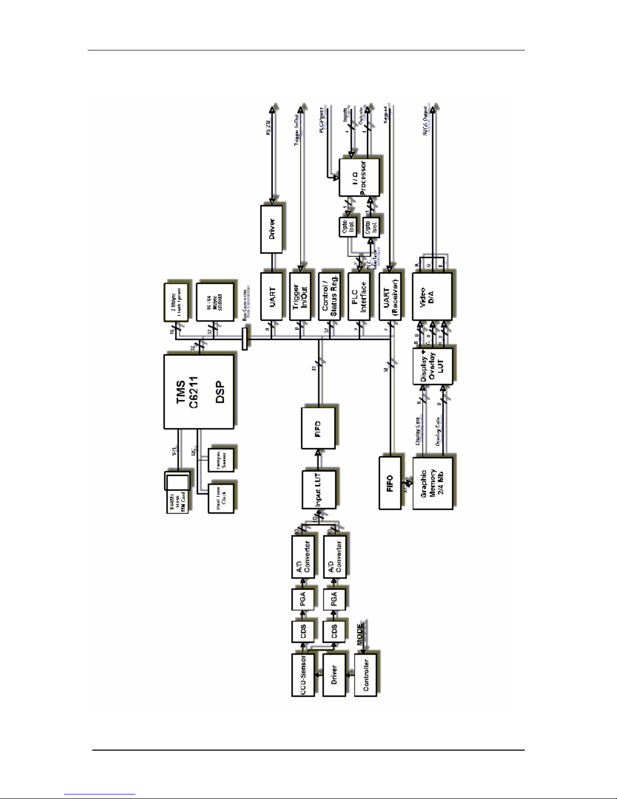
2 Basic Structure
The image is formed by a high-resolution progressive scan CCD sensor. One or two channels of video
output are digitized. An input lookup-table is available for basic pixel-preprocessing. The image is
stored in SDRAM memory using one of the 16 DMA channels (EDMA).
The video and graphics display on the monitor is performed in a very similar way: Data is stored in the
main SDRAM memory, either due to a previous video capture or to computing by the DSP. Graphics
data is then transferred to the graphics refresh buffer (SGRAM). This may happen periodically or on
demand. The SGRAM is read out at a fast refresh rate to provide a high-quality, flickerfree display.
A dual 3x256x8 output lookup-table gives you abundant choices for the appearance of images and
graphics.
The video capture and graphics output channels are completely independent. The storage area for
each may be chosen to be identical (necessary for live image display) or completely different. If the
latter is chosen, you may capture an image "in the background" while displaying a completely different
one.
The TMS320C6211 DSP is one of the fastest 32 DSPs. It features a RISC-like instruction set, up to 8
instructions can be executed in parallel, two L1 cache memories (4KBytes each) and a 64 KByte L2
cache on chip. Its high speed 16-channel DMA controller gives additional performance. The DSP uses
fast external SDRAM as main memory. A flash EPROM and a built-in multi-media card provide nonvolatile memory.
See
Appendix A: Blockdiagram VC20XX Smart Cameras.
© 1996-2007 Vision Components GmbH Ettlingen, Germany VC20XX_HW.pdf
Page 9
VC20XX Operating Manual
5
3 Boards
The electronic circuitry of the camera contains four printed curcuit boards (PCB).
The following presents an overview of the boards:
Description Designation Function
Sensor boards
C6SEN084, C6SEN204
C6SEN205, C6SEN311
C6SEN415
CCD sensor, driver & controller,
digitization of the video signal, blackand-white and color versions
CPU board
C6CPU
TMSC6211 signal processor with
SDRAM, FLASH memory, multi-media
card adaptor
DAC board
C6DAC
SVGA quality video output with graphics
memory, video capture, interfaces
(RS232, etc.)
Power board
C6PWR Power supply, PLC interfaces
3.1 Sensor Boards
Camera Type Sensor Board
VC2028 C6SEN084
VC2038 C6SEN084
VC2038/E C6SEN084
VC2048/E C6SEN311
VC2065 C6SEN415
VC2065/E C6SEN415
VC2065/C C6SEN415
VC2065/EC C6SEN415
VC2066 C6SEN204
VC2066/E C6SEN204
VC2068 C6SEN205
VC2068/E C6SEN205
© 1996-2007 Vision Components GmbH Ettlingen, Germany VC20XX_HW.pdf
Page 10

VC20XX Operating Manual
6
3.1.1 C6SEN084
This board takes the picture. It is used in the VC2028, VC2038 and VC2038/E
The CCD sensor 1/3" SONY ICX424AL (B/W) is used. The board controls the CCD sensor and
processes the analog signal.
The progressive scan type CCD sensor used is ideally suited for industrial machine vision tasks. In
contrast to the conventional technique it provides the following features:
• 1/3" sensor
• resolution: 640x480 pixels
• square pixel format, 7.4(H) x 7.4(V) µm
• full-frame shutter
• can be triggered externally (except VC2028)
• sensor read out in full-frame mode (non-interlaced)
• shutter speed down to 30,80,... µsec in steps of 50 microseconds up to 20 sec
• 40fps @ 640x480 (VC2028 : 25fps@640x480)
• CCD processors providin g CDS, programmable gain and offset, auto black level
compensation and 10 bit AD-conversion
The diverse features of this board (high-speed and low-speed shutter, external trigger, etc.) are
configured via software.
For the exact setting of the configuration, refer to the description of the configuration program in the
software documentation.
3.1.2 C6SEN204
This board takes the picture. It is used in the VC2066 and VC2066/E
The CCD sensor ICX204AL (B/W) is used. The board controls the CCD sensor and processes the
analog signal.
The progressive scan type CCD sensor used is ideally suited for industrial machine vision tasks. In
contrast to the conventional technique it provides the following features:
• 1/3" sensor
• higher resolution: 1024x768 pixels
• square pixel format, 4.64 µ m
• full-frame shutter
• can be triggered externally
• sensor read out in full-frame mode (non-interlaced)
• shutter speed down to 10 µsec and up to 20 sec
• 16fps @ 640x480 or 2 x binning @ 32fps
• CCD processors providin g CDS, programmable gain and offset, auto black level
compensation and 10 bit AD-conversion
The diverse features of this board (high-speed and low-speed shutter, external trigger, etc.) are
configured via software.
© 1996-2007 Vision Components GmbH Ettlingen, Germany VC20XX_HW.pdf
Page 11

VC20XX Operating Manual
7
For the exact setting of the configuration, refer to the description of the configuration program in the
software documentation.
3.1.3 C6SEN205
This board takes the picture. It is used in the VC2068 and VC2068/E
The CCD sensor ICX205AL (B/W) is used. The board controls the CCD sensor and processes the
analog signal.
The progressive scan type CCD sensor used is ideally suited for industrial machine vision tasks. In
contrast to the conventional technique it provides the following features:
• 1/2" sensor
• higher resolution: 1280x1024 pixels
• square pixel format, 4.65 µ m
• full-frame shutter
• can be triggered externally
• sensor read out in full-frame mode (non-interlaced)
• shutter speed down to 9 µsec and up to 20 sec
• 13,75fps @ 1280x1024 or 2 x binning @ 27,5fps
• CCD processors providin g CDS, programmable gain and offset, auto black level
compensation and 10 bit AD-conversion
The diverse features of this board (high-speed and low-speed shutter, external trigger, etc.) are
configured via software.
For the exact setting of the configuration, refer to the description of the configuration program in the
software documentation.
3.1.4 C6SEN311
This board takes the picture. It is used in the VC2048/E
The CCD sensor KAI0330D (B/W) is used. The board controls the CCD sensor and processes the
analog signal.
The progressive scan type CCD sensor used is ideally suited for industrial machine vision tasks. In
contrast to the conventional technique it provides the following features:
• 1/2" sensor
• resolution: 640x480 pixels
• square pixel format, 9(H) x 9(V) µm
• full-frame shutter
• can be triggered externally
• sensor read out in full-frame mode (non-interlaced)
• shutter speed down to 18,36,72, µsec then steps of 36 microseconds up to 20 sec
• 112fps @ 640x480 !!!
• CCD processors providin g CDS, programmable gain and offset, auto black level
compensation and 10 bit AD-conversion
© 1996-2007 Vision Components GmbH Ettlingen, Germany VC20XX_HW.pdf
Page 12

VC20XX Operating Manual
8
The diverse features of this board (high-speed and low-speed shutter, external trigger, etc.) are
configured via software.
For the exact setting of the configuration, refer to the description of the configuration program in the
software documentation.
3.1.5 C6SEN415
This board takes the picture. It is used in the VC2065, VC2065/E, VC2065/C and VC2065/EC.
The CCD sensor ICX415AL (black-and-white) or ICX415AK (color) is used. The board controls the
CCD sensor and processes the analog signal.
The progressive scan type CCD sensor used is ideally suited for industrial machine vision tasks. In
contrast to the conventional technique it provides the following features:
• 1/2" sensor
• higher resolution: 782x582 pixels
• square pixel format
• full-frame shutter
• can be triggered externally
• sensor read out in full-frame mode (non-interlaced)
• shutter speed down to 5 µsec and up to 20 sec
• double speed video capture @ 45fps
• CCD processors providin g CDS, programmable gain and offset, auto black level
compensation and 10 bit AD-conversion
The diverse features of this board (high-speed and low-speed shutter, external trigger, etc.) are
configured via software.
For the exact setting of the configuration, refer to the description of the configuration program in the
software documentation.
3.2 CPU Board
The "C6CPU" Board
The TMS320C6211 DSP is one of the fastest 32 bit DSPs. It features a RISC-like instruction set, up to
8 instructions can be executed in parallel. Turthermore it features two L1 cache memories (4KBytes
each) and a 64 KByte L2 cache on chip.
The DSP uses fast external SDRAM as main memory. Up to 4 memory banks can be permanently
open providing fast access without unnecessary RAS commands.
A flash EPROM and a built-in multi-media card provide for non-volatile memory.
Most of the I/O functions (graphics display, video capture, etc.) are performed by Vision Components'
proprietary DMA Hardware without overhead for the CPU.
© 1996-2007 Vision Components GmbH Ettlingen, Germany VC20XX_HW.pdf
Page 13

VC20XX Operating Manual
9
The location of the SDRAM buffers for graphics display, overlay display and video capture can be
selected independently.
Identical SDRAM buffers for graphics display and video capture may be chosen to produce live video
display.
Board C6CPU
processor TMS320C6211 150MHz
SDRAM 16 Mbytes (400 MB/sec)
Flash-EPROM 2 Mbytes (16bit wide)
Multi-Media Card Adaptor 8-256 MBytes
Clock Real time clock, battery backed-up
DMA
16 independent DMA channels (EDMA) 1 very high speed
DMA (QDMA)
special features on-board temperature sensor
3.3 DAC Board
The "C6DAC" Board
The "C6DAC" board is practically the periphery for the CPU board. Here, the digital video signal from
the sensor board is the input using an input lookup-table and buffered with FIFO memory.
The board is also responsible for the SVGA graphics output. Graphics (8 bits per pixel) and overlay
data (8 bits per pixel) are stored in the on-board SGRAM. 2 independent lookup-tables for graphics
and overlay data together with a 3x8 bits D/A converter produce the RGB analog video for the SVGA
output.
The 8 bit pixel-mask register allows for individual selection of overlay planes.
Overlay data have priority over graphics data. Graphics pixels are displayed only if all unmasked
overlay bits for that pixel are zero.
Functions of the board:
• video capture with input LUT, FIFO buffer
• graphics and overlay display with 16 Mbytes refresh memory,
• 2 independent LUTs for graphics and overlay, 8bit overlay mask register
• 3x8bit video D/A (SVGA output)
• UART and driver for RS232 (Ethernet versions : Ethernet PHY)
• UART receiver for VC Keypad (9600 baud)
• Trigger In/Out signals
• PLC communication inte rface
• Status & Control Register
• Interrupt controller for CPU
• DMA Controller
© 1996-2007 Vision Components GmbH Ettlingen, Germany VC20XX_HW.pdf
Page 14
VC20XX Operating Manual
10
The technical specifications for the SVGA output signals :
Horizontal frequency: 45.072 kHz VBP: 32 lines
Vertical frequency: 67.68 Hz VFP: 46 lines
Resolution SVGA: 600x800 HSYNC width: 120 pixels
Resolution eff. hor.: 752 HBP: 94 pixels
Resolution eff. ver.: 582 HFP: 74 pixels
VSYNC width: 6 lines Pixel frequency: 46.875 MHz
Polarity HSYNC: positive Polarity VSYNC: positive
The technical specifications for the SXGA output signals :
Horizontal frequency: 64 kHz VBP: 37 lines
Vertical frequency: 60 Hz VFP: 2 lines
Resolution SXGA: 1280x1024 HSYNC width: 130 pixels
Resolution eff. hor.: 1280 HBP: 487 pixels
Resolution eff. ver.: 1024 HFP: 55 pixels
VSYNC width: 3 lines Pixel frequency: 125 MHz
Polarity HSYNC: positive Polarity VSYNC: positive
3.4 Power Board
The "C6PWR" Board
This board contains the power supply for the entire camera. It is also responsible for the galvanic
separation of the signals, and tailors the levels of the PLC-signals (4 inputs, 4 outputs).
The camera is supplied with a nominal voltage of 24 V (+/- 20%). An electronic stabilization of the
supply voltage is not necessary. The camera is internally galvanically separated from the supply
voltage by means of a DC/DC converter, to avoid common ground loops and electromagnetic
interference. A reverse-voltage protection diode protects the camera in case the supply voltage poles
are swapped.
An I/O processor performs PLC I/O , and also monitors PLC voltage failures and overcurrent.
© 1996-2007 Vision Components GmbH Ettlingen, Germany VC20XX_HW.pdf
Page 15

VC20XX Operating Manual
11
4 PLC I/O Signals
The camera has four optically decoupled inputs and four decoupled outputs for controlling machines
and processes.
An I/O processor is responsible for the handling of the PLC I/O signals.
The PLC-compatible inputs (24-V level, the positive signal is connected) include input protection
circuits. A minimum voltage of 14V is required to reliably sense a logic high signal.
The PLC outputs feature a highly integrated MOSFET, high-side switch with built-in protection . It is
possible to switch inductive or capacitive loads. The protective feature of the outputs will produce
pulses on the outputs, if the limiting values are exceeded.
A protective diode ensures, the poles of the supply voltage from the power supply of the PLC can not
be swapped. It is important to connect both the external supply voltage of the outputs (+24V) as well
as GND (GNDIn) of the power supply of the PLC.
The complete circuitry, including the I/O processor, is galvanically separated from the rest of the
camera electronics.
If DC failure of the PLC power is detected, this information is forwarded to the DSP (PLC power failure
interrupt)
Output drivers feature short circuit end thermal overload protection
For additional protection of the output drivers, the I/O processor monitors the total PLC current, and
switches off all outputs if the maximum threshold value is exceeded.
Technical data of the I/O signals:
Inputs
Outputs
Trigger input and trigger output
4.1 Input Signals
Nominal voltage: 24 V +/- 20%
Absolute maximum voltage: voltages greater than 40 V can destroy the inputs
Type:
galvanically separated by optocoupler (PLC
communication interface)
Input current: 1 mA @ 24V
Threshold value: 14 V
Internal signal delay:
100 µsec (signal) + 0..200 µsec (polling) + DSP interrupt
latency
© 1996-2007 Vision Components GmbH Ettlingen, Germany VC20XX_HW.pdf
Page 16

VC20XX Operating Manual
12
4.2 Output Signals
Operating voltage: 24 V +/- 20%, external source
Absolute maximum voltage: voltages greater than 40 V can destroy the outputs
Type: galvanically separated by MOSFET optocouplers
Switching voltage: positive switching
Current: max. 400 mA per output
Absolute maximum current:
total currents greater than 1000 mA can destroy plugs and
cables
Always consider the total sum of all output currents
Switching power: max. 9.6 W (24 V * 400 mA) per output
Reverse voltage protection yes, for external voltage
Protection against inductive
loads:
yes
Resistance when switched on: 0.2 - 0.8 Ohm
Short circuit protection: full protection
4.3 Trigger input and trigger output
The board features a dedicated fast TTL trigger input (for use as image capture trigger) and a fast TTL
trigger output (as strobe-light trigger). Since both signals are fast at a very low noise margin, it is
recommended to keep the cable as short as possible. Use twisted pair or even coaxial cable for this
purpose. The trigger input has a built-in photocoupler to eliminate ground loops with the external
circuitry. The trigger output, however, is not galvanically separated. The receiving circuit should,
therefore, have a photocoupler of its own.
Please note that input and output are not protected against overcurrent. The output is neither
protected against short circuit nor reverse voltage spikes from inductive loads.
Trigger input assures constant delay without jitter.
Technical data of trigger input:
input voltage: 3-5 V (TTL, CMOS)
input current: 5mA @ 3V / 11mA @ 5V
limiting resistor: built in, 330 Ohm
knee voltage: 1.5 V
reverse voltage protection: shunt diode
switching delay: max. 2µsec + interrupt latency
Trig. In+
yellow cable
Trig. Ingreen cable
330 R
© 1996-2007 Vision Components GmbH Ettlingen, Germany VC20XX_HW.pdf
Page 17

VC20XX Operating Manual
13
Technical data of trigger output:
output voltage: max. 7V
output current: max. 50mA
pull-up resistor: none, external resistor required
© 1996-2007 Vision Components GmbH Ettlingen, Germany VC20XX_HW.pdf
Page 18

VC20XX Operating Manual
14
5 Pin Assignments Camera Interfaces
The cameras have four connectors on the rear side:
RS232(V24) or
100MBd Ethernet
HR10A-7R-6PB 6-pin Hirose plug pin contact
Trigger / Keypad HR10A-7R-6SB 6-pin Hirose plug jack contact
SXGA/SVGA/Video HR10A-10R-10SB 10-pin Hirose plug jack contact
DC IN/PLC-I/O HR10A-10R-12PB 12-pin Hirose plug pin contact
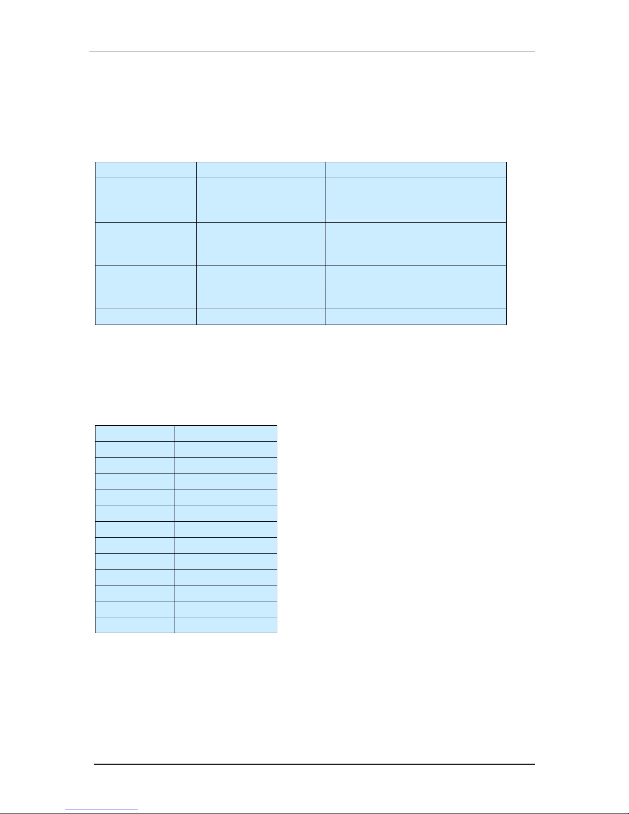
5.1 Pin Assignment Trigger / Keypad Plug Signal
rear view (jack):
Signal Pin
GND 3
5V Out 2
Trigger IN - 1
Trigger IN + 6
Trigger Out 5
Keypad IN 4
They Keypad IN operates with 3.3V TTL @9600 baud / 8 / N / 1
5.2 Pin Assignment for the I/O Plug
Rear view: (pin)
Signal Pin
IN0 12
IN1 4
IN2 11
IN3 10
24V IN / Cam 2
GND IN (common) 3
24V IN/ PLC 1
24V IN/ PLC 9
OUT0 8
OUT1 7
OUT2 6
OUT3 5
© 1996-2007 Vision Components GmbH Ettlingen, Germany VC20XX_HW.pdf
Page 19
VC20XX Operating Manual
15
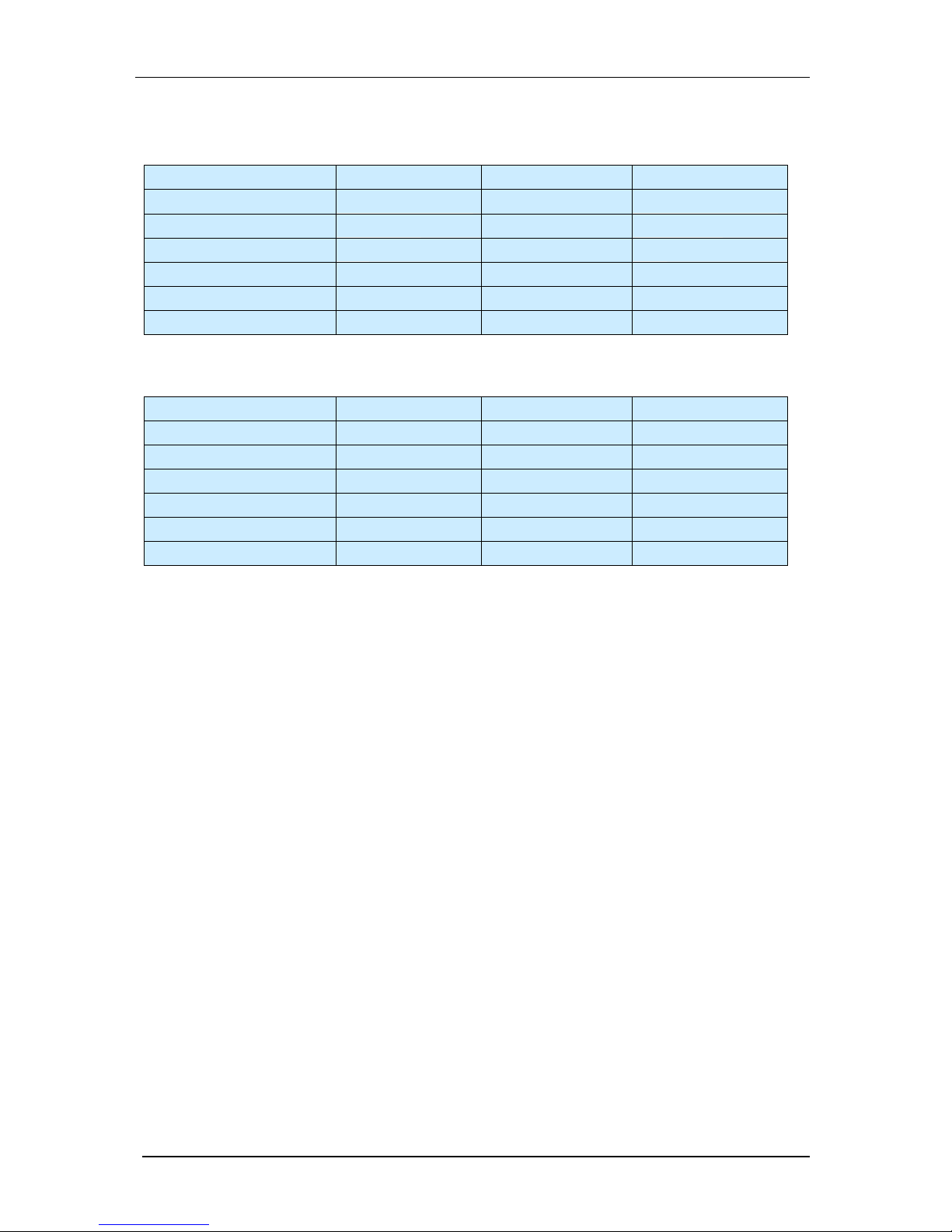
5.3 Pin Assignment for the RS232 (V24)
Rear view: (pin)
Signal Pin
V24 RTS 1
V24 TxD 2
V24 GND 3
NC V24 4
V24 CTS 5
RxD 6
5.4 Pin Assignment LAN/Ethernet
Rear view: (pin)
Signal Pin
T- 1
T+ 2
- 3
- 4
R- 5
R+ 6
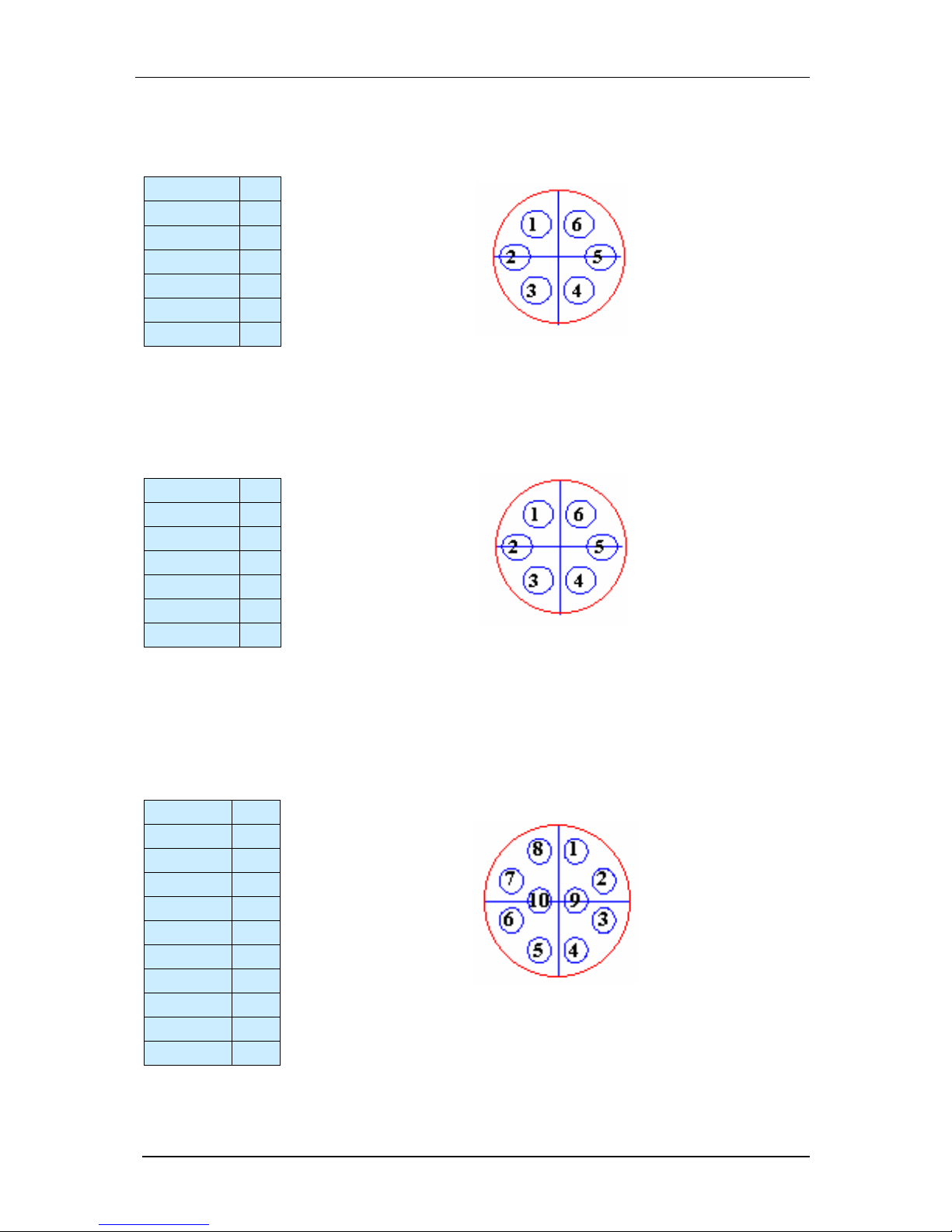
5.5 Pin Assignment for the XGA/SVGA Video Output
rear view (jack):
Signal Pin
G GND 1
G Out 2
R GND 3
R Out 4
VS GND 5
VS Out 6
HS GND 7
B GND 8
B Out 9
HS Out 10
© 1996-2007 Vision Components GmbH Ettlingen, Germany VC20XX_HW.pdf
Page 20

VC20XX Operating Manual
16
6 Technical Specifications VC20XX Smart Cameras
Technical Specifications VC2028
Technical Specifications VC2038 Technical Specifications VC2038/E
Technical Specifications VC2048/E
Technical Specifications VC2065 TechnicalSpecifications VC2065/E
Technical Specifications VC2065/C Technical Specifications VC2065/EC
Technical Specifications VC2066 Technical Specifications VC2066/E
Technical Specifications VC2068 Technical Specifications VC2068/E
6.1 Technical Specifications VC2028
Sensor: 1/3" SONY ICX424AL
eff. no. of pixels: 640(H) x 480(V)
Pixel size: 7.4(H) x 7.4(V) µm
Chip size: 5.79(H) x 4.89(V) mm
High-speed shutter: 30,80,... microseconds in steps of 50 microseconds (full-
frame shutter)
Low-speed shutter: up to 20 sec. adjustable integration time
Integration: full-frame
Picture taking: with 15msec delay, program-controlled ; full-frame / 25
frames per second, no external highspeed trigger
1
Clamping: zero offset digital clamping
A/D conversion: 15.625 MHz / 10 bit,
Input LUT 1024x8 bit (10bit → 8 bit)
Image display: black-and-white, Pseudo Color from color lookup table
3x8Bit RGB:live image, still image, graphics
Overlay: 8-bit overlay with LUT, maskable
Processor: Texas Instruments TMS320C6211 signal processor 150
MHz
RAM: 16 MBytes SDRAM (synchronous dynamic RAM)
Display memory: 16 MBytes SGRAM (synchronous graphics RAM)
Memory capacity: 40 full-size images in format 640x480
Flash EPROM: 2 MBytes flash EPROM (nonvolatile memory) for
programs and data,in-system programmable, 16 bit wide
MMC:
Not available
Process interface: 4 inputs / 4 o utputs, optically decoupled 24 V, outputs
4x400 mA
Serial interface: V24 (RS232) max. 115200 baud
Video output: RGB, 3x75 Ohm, 1 Vpp, SVGA 800x600 output, HSYNC,
VSYNC separate
Horizontal frequency: 45.072 kHz
Vertical frequency: 67.68 Hz
Resolution SVGA: 600x800
Pixel frequency: 46.875 MHz
!
1
Use VC2038 instead of VC2028 for imaging moving objects.
© 1996-2007 Vision Components GmbH Ettlingen, Germany VC20XX_HW.pdf
Page 21

VC20XX Operating Manual
17
6.2 Technical Specifications VC2038
Sensor: 1/3" SONY ICX424AL
eff. no. of pixels: 640(H) x 480(V)
Pixel size: 7.4(H) x 7.4(V) µm
Chip size: 5.79(H) x 4.89(V) mm
High-speed shutter:
30,80,... microseconds in steps of 50 microseconds (full-
frame shutter)
Low-speed shutter: up to 20 sec. adjustable integration time
Integration: full-frame
Picture taking:
without delay, program-controlled or triggered externally;
full-frame / 40 frames per second
Clamping: zero offset digital clamping
A/D conversion: 15.625 MHz / 10 bit,
Input LUT 1024x8 bit (10bit → 8 bit)
Image display:
black-and-white, Pseudo Color from color lookup table
3x8Bit RGB:live image, still image, graphics
Overlay: 8-bit overlay with LUT, maskable
Processor:
Texas Instruments TMS320C6211 signal processor 150
MHz
RAM: 16 MBytes SDRAM (synchronous dynamic RAM)
Display memory: 16 MBytes SGRAM (synchronous graphics RAM)
Memory capacity: 40 full-size images in format 640x480
Flash EPROM:
2 MBytes flash EPROM (nonvolatile memory) for
programs and data,in-system programmable, 16 bit wide
MMC:
Multi-Media Card Adaptor with 16 Mbyte of Card Flash
Memory
Process interface:
4 inputs / 4 outputs, optically decoupled 24 V, outputs
4x400 mA
Serial interface: V24 (RS232) max. 115200 baud
Video output:
RGB, 3x75 Ohm, 1 Vpp, SVGA 800x600 output, HSYNC,
VSYNC separate
Horizontal frequency: 45.072 kHz
Vertical frequency: 67.68 Hz
Resolution SVGA: 600x800
Pixel frequency: 46.875 MHz
© 1996-2007 Vision Components GmbH Ettlingen, Germany VC20XX_HW.pdf
Page 22

VC20XX Operating Manual
18
6.3 Technical Specifications VC2038/E
Sensor: 1/3" SONY ICX424AL
eff. no. of pixels: 640(H) x 480(V)
Pixel size: 7.4(H) x 7.4(V) µm
Chip size: 5.79(H) x 4.89(V) mm
High-speed shutter:
30,80,... microseconds in steps of 50 microseconds (full-
frame shutter)
Low-speed shutter: up to 20 sec. adjustable integration time
Integration: full-frame
Picture taking:
without delay, program-controlled or triggered externally;
full-frame / 40 frames per second
Clamping: zero offset digital clamping
A/D conversion: 15.625 MHz / 10 bit,
Input LUT 1024x8 bit (10bit → 8 bit)
Image display:
black-and-white, Pseudo Color from color lookup table
3x8Bit RGB:live image, still image, graphics
Overlay: 8-bit overlay with LUT, maskable
Processor:
Texas Instruments TMS320C6211 signal processor 150
MHz
RAM: 16 MBytes SDRAM (synchronous dynamic RAM)
Display memory: 16 MBytes SGRAM (synchronous graphics RAM)
Memory capacity: 40 full-size images in format 640x480
Flash EPROM:
2 MBytes flash EPROM (nonvolatile memory) for
programs and data,in-system programmable, 16 bit wide
MMC:
Multi-Media Card Adaptor with 16 Mbyte of Card Flash
Memory
Process interface:
4 inputs / 4 outputs, optically decoupled 24 V, outputs
4x400 mA
Ethernet interface: 100 MBit
Video output:
RGB, 3x75 Ohm, 1 Vpp, SVGA 800x600 output, HSYNC,
VSYNC separate
Horizontal frequency: 45.072 kHz
Vertical frequency: 67.68 Hz
Resolution SVGA: 600x800
Pixel frequency: 46.875 MHz
© 1996-2007 Vision Components GmbH Ettlingen, Germany VC20XX_HW.pdf
Page 23

VC20XX Operating Manual
19
6.4 Technical Specifications VC2048/E
Sensor: 1/2" KODAK KAI-0330D
eff. no. of pixels: 640(H) x 480(V)
Pixel size: 9(H) x 9(V) µm
Chip size: 7.3(H) x 5.52(V) mm
High-speed shutter:
18,36,72, microseconds in steps of 36 microseconds (full-
frame shutter)
Low-speed shutter: up to 20 sec. adjustable integration time
Integration: full-frame
Picture taking:
without delay, program-controlled or triggered externally;
full-frame / 112 frames per second
Clamping: zero offset digital clamping
A/D conversion: 2 x 24 MHz / 10 bit,
Input LUT 1024x8 bit (10bit → 8 bit)
Image display:
black-and-white, Pseudo Color from color lookup table
3x8Bit RGB:live image, still image, graphics
Overlay: 8-bit overlay with LUT, maskable
Processor:
Texas Instruments TMS320C6211 signal processor 150
MHz
RAM: 16 MBytes SDRAM (synchronous dynamic RAM)
Display memory: 16 MBytes SGRAM (synchronous graphics RAM)
Memory capacity: 40 full-size images in format 640 x 480
Flash EPROM:
2 MBytes flash EPROM (nonvolatile memory) for
programs and data,in-system programmable, 16 bit wide
MMC:
Multi-Media Card Adaptor with 16 Mbyte of Card Flash
Memory
Process interface:
4 inputs / 4 outputs, optically decoupled 24 V, outputs
4x400 mA
Ethernet interface: 100Mbit Ethernet
Video output:
RGB, 3x75 Ohm, 1 Vpp, SVGA 800x600 output, HSYNC,
VSYNC separate
Horizontal frequency: 45.072 kHz
Vertical frequency: 67.68 Hz
Resolution SVGA: 600x800
Pixel frequency: 46.875 MHz
© 1996-2007 Vision Components GmbH Ettlingen, Germany VC20XX_HW.pdf
Page 24

VC20XX Operating Manual
20
6.5 Technical Specifications VC2065
Sensor: 1/2" SONY ICX415AL
eff. no. of pixels: 782(H) x 582(V)
Pixel size: 8.3(H) x 8.3(V) µm
Chip size: 7.48(H) x 6.15(V) mm
High-speed shutter:
5,10,15,20, microseconds in steps of 40 microseconds
(full-frame shutter)
Low-speed shutter: up to 20 sec. adjustable integration time
Integration: full-frame
Picture taking:
without delay, program-controlled or triggered externally;
full-frame / 45 frames per second
Clamping: zero offset digital clamping
A/D conversion: 24 MHz / 10 bit,
Input LUT 1024x8 bit (10bit → 8 bit)
Image display:
black-and-white, Pseudo Color from color lookup table
3x8Bit RGB:live image, still image, graphics
Overlay: 8-bit overlay with LUT, maskable
Processor:
Texas Instruments TMS320C6211 signal processor 150
MHz
RAM: 16 MBytes SDRAM (synchronous dynamic RAM)
Display memory: 16 MBytes SGRAM (synchronous graphics RAM)
Memory capacity: 35 full-size images in format 782 x 582
Flash EPROM:
2 MBytes flash EPROM (nonvolatile memory) for
programs and data,in-system programmable, 16 bit wide
MMC:
Multi-Media Card Adaptor with 16 Mbyte of Card Flash
Memory
Process interface:
4 inputs / 4 outputs, optically decoupled 24 V, outputs
4x400 mA
Serial interface: V24 (RS232) max. 115200 baud
Video output:
RGB, 3x75 Ohm, 1 Vpp, SVGA 800x600 output, HSYNC,
VSYNC separate
Horizontal frequency: 45.072 kHz
Vertical frequency: 67.68 Hz
Resolution SVGA: 600x800
Pixel frequency: 46.875 MHz
© 1996-2007 Vision Components GmbH Ettlingen, Germany VC20XX_HW.pdf
Page 25

VC20XX Operating Manual
21
6.6 Technical Specifications VC2065/C
Sensor: 1/2" SONY ICX415AK color sensor
eff. no. of pixels: 782(H) x 582(V)
Pixel size: 8.3(H) x 8.3(V) µm
Chip size: 7.48(H) x 6.15(V) mm
High-speed shutter:
5,10,15,20, microseconds in steps of 40 microseconds
(full-frame shutter)
Low-speed shutter: up to 20 sec. adjustable integration time
Integration: full-frame
Picture taking:
without delay, program-controlled or triggered externally;
full-frame / 45 frames per second
Clamping: zero offset digital clamping
A/D conversion: 24 MHz / 10 bit,
Input LUT 1024x8 bit (10bit → 8 bit)
Image display:
black-and-white, Pseudo Color from color lookup table
3x8Bit RGB:live image, still image, graphics
Overlay: 8-bit overlay with LUT, maskable
Processor:
Texas Instruments TMS320C6211 signal processor 150
MHz
RAM: 16 MBytes SDRAM (synchronous dynamic RAM)
Display memory: 16 MBytes SGRAM (synchronous graphics RAM)
Memory capacity: 35 full-size images in format 782 x 582
Flash EPROM:
2 MBytes flash EPROM (nonvolatile memory) for
programs and data,in-system programmable, 16 bit wide
MMC:
Multi-Media Card Adaptor with 16 Mbyte of Card Flash
Memory
Process interface:
4 inputs / 4 outputs, optically decoupled 24 V, outputs
4x400 mA
Serial interface: V24 (RS232) max. 115200 baud
Video output:
RGB, 3x75 Ohm, 1 Vpp, SVGA 800x600 output, HSYNC,
VSYNC separate
Horizontal frequency: 45.072 kHz
Vertical frequency: 67.68 Hz
Resolution SVGA: 600x800
Pixel frequency: 46.875 MHz
© 1996-2007 Vision Components GmbH Ettlingen, Germany VC20XX_HW.pdf
Page 26

VC20XX Operating Manual
22
6.7 Technical Specifications VC2065/E
Sensor: 1/2" SONY ICX415AL
eff. no. of pixels: 782(H) x 582(V)
Pixel size: 8.3(H) x 8.3(V) µm
Chip size: 7.48(H) x 6.15(V) mm
High-speed shutter:
5,10,15,20, microseconds in steps of 40 microseconds
(full-frame shutter)
Low-speed shutter: up to 20 sec. adjustable integration time
Integration: full-frame
Picture taking:
without delay, program-controlled or triggered externally;
full-frame / 45 frames per second
Clamping: zero offset digital clamping
A/D conversion: 24 MHz / 10 bit,
Input LUT 1024x8 bit (10bit → 8 bit)
Image display:
black-and-white, Pseudo Color from color lookup table
3x8Bit RGB:live image, still image, graphics
Overlay: 8-bit overlay with LUT, maskable
Processor:
Texas Instruments TMS320C6211 signal processor 150
MHz
RAM: 16 MBytes SDRAM (synchronous dynamic RAM)
Display memory: 16 MBytes SGRAM (synchronous graphics RAM)
Memory capacity: 35 full-size images in format 782 x 582
Flash EPROM:
2 MBytes flash EPROM (nonvolatile memory) for
programs and data,in-system programmable, 16 bit wide
MMC:
Multi-Media Card Adaptor with 16 Mbyte of Card Flash
Memory
Process interface:
4 inputs / 4 outputs, optically decoupled 24 V, outputs
4x400 mA
Ethernet Interface 100Mbit Ethernet
Video output:
RGB, 3x75 Ohm, 1 Vpp, SVGA 800x600 output, HSYNC,
VSYNC separate
Horizontal frequency: 45.072 kHz
Vertical frequency: 67.68 Hz
Resolution SVGA: 600x800
Pixel frequency: 46.875 MHz
© 1996-2007 Vision Components GmbH Ettlingen, Germany VC20XX_HW.pdf
Page 27

VC20XX Operating Manual
23
6.8 Technical Specifications VC2065/EC
Sensor: 1/2" SONY ICX415AK color sensor
eff. no. of pixels: 782(H) x 582(V)
Pixel size: 8.3(H) x 8.3(V) µm
Chip size: 7.48(H) x 6.15(V) mm
High-speed shutter:
5,10,15,20, microseconds in steps of 40 microseconds
(full-frame shutter)
Low-speed shutter: up to 20 sec. adjustable integration time
Integration: full-frame
Picture taking:
without delay, program-controlled or triggered externally;
full-frame / 45 frames per second
Clamping: zero offset digital clamping
A/D conversion: 24 MHz / 10 bit,
Input LUT 1024x8 bit (10bit → 8 bit)
Image display:
black-and-white, Pseudo Color from color lookup table
3x8Bit RGB:live image, still image, graphics
Overlay: 8-bit overlay with LUT, maskable
Processor:
Texas Instruments TMS320C6211 signal processor 150
MHz
RAM: 16 MBytes SDRAM (synchronous dynamic RAM)
Display memory: 16 MBytes SGRAM (synchronous graphics RAM)
Memory capacity: 35 full-size images in format 782 x 582
Flash EPROM:
2 MBytes flash EPROM (nonvolatile memory) for
programs and data,in-system programmable, 16 bit wide
MMC:
Multi-Media Card Adaptor with 16 Mbyte of Card Flash
Memory
Process interface:
4 inputs / 4 outputs, optically decoupled 24 V, outputs
4x400 mA
Ethernet interface: 100Mbit Ethernet
Video output:
RGB, 3x75 Ohm, 1 Vpp, SVGA 800x600 output, HSYNC,
VSYNC separate
Horizontal frequency: 45.072 kHz
Vertical frequency: 67.68 Hz
Resolution SVGA: 600x800
Pixel frequency: 46.875 MHz
© 1996-2007 Vision Components GmbH Ettlingen, Germany VC20XX_HW.pdf
Page 28

VC20XX Operating Manual
24
6.9 Technical Specifications VC2066
Sensor: 1/3" SONY ICX204AL
eff. no. of pixels: 1024(H) x 768(V)
Pixel size: 4.65(H) x 4.65(V) µm
Chip size: 5.8(H) x 4.92(V) mm
High-speed shutter:
10,20,30,45 µsec, then steps of 78 µsec (full-frame
shutter)
Low-speed shutter: up to 20 sec. adjustable integration time
Integration: full-frame
Picture taking:
without delay, program-controlled or triggered externally;
full-frame / 16.5 frames per second (2x binning @ 33fps)
Clamping: zero offset digital clamping
A/D conversion: 15.625 MHz / 10 bit,
Input LUT 1024x8 bit (10bit → 8 bit)
Image display:
black-and-white, Pseudo Color from color lookup table
3x8Bit RGB:live image, still image, graphics
Overlay: 8-bit overlay with LUT, maskable
Processor:
Texas Instruments TMS320C6211 signal processor 150
MHz
RAM: 16 MBytes SDRAM (synchronous dynamic RAM)
Display memory: 16 MBytes SGRAM (synchronous graphics RAM)
Memory capacity: 20 full-size images in format 1024x768
Flash EPROM:
2 MBytes flash EPROM (nonvolatile memory) for
programs and data,in-system programmable, 16 bit wide
MMC:
Multi-Media Card Adaptor with 16 Mbyte of Card Flash
Memory
Process interface:
4 inputs / 4 outputs, optically decoupled 24 V, outputs
4x400 mA
Serial interface: V24 (RS232) max. 115200 baud
Video output:
RGB, 3x75 Ohm, 1 Vpp, SXVGA 1280x1024 output,
HSYNC, VSYNC separate
Horizontal frequency: 64kHz
Vertical frequency: 60Hz
Resolution SXGA: 1280x1024
Pixel frequency:
125MHz – when using a TFT, ensure the monitor is
cablable of 125Mhz pixel frequency (i.e. TFT’s with 80Hz
image frequency).
!
© 1996-2007 Vision Components GmbH Ettlingen, Germany VC20XX_HW.pdf
Page 29

VC20XX Operating Manual
25
6.10 Technical Specifications VC2066/E
Sensor: 1/3" SONY ICX204AL
eff. no. of pixels: 1024(H) x 768(V)
Pixel size: 4.65(H) x 4.65(V) µm
Chip size: 5.8(H) x 4.92(V) mm
High-speed shutter:
10,20,30,45 microseconds, longer in steps of 78
microseconds (full-frame shutter)
Low-speed shutter: up to 20 sec. adjustable integration time
Integration: full-frame
Picture taking:
without delay, program-controlled or triggered externally;
full-frame / 16.5 frames per second (2x binning @ 33fps)
Clamping: zero offset digital clamping
A/D conversion: 15.625 MHz / 10 bit,
Input LUT 1024x8 bit (10bit → 8 bit)
Image display:
black-and-white, Pseudo Color from color lookup table
3x8Bit RGB:live image, still image, graphics
Overlay: 8-bit overlay with LUT, maskable
Processor:
Texas Instruments TMS320C6211 signal processor 150
MHz
RAM: 16 MBytes SDRAM (synchronous dynamic RAM)
Display memory: 16 MBytes SGRAM (synchronous graphics RAM)
Memory capacity: 20 full-size images in format 1024x768
Flash EPROM:
2 MBytes flash EPROM (nonvolatile memory) for
programs and data,in-system programmable, 16 bit wide
MMC:
Multi-Media Card Adaptor with 16 Mbyte of Card Flash
Memory
Process interface:
4 inputs / 4 outputs, optically decoupled 24 V, outputs
4x400 mA
Ethernet Interface: 100 Mbit
Video output:
RGB, 3x75 Ohm, 1 Vpp, SXVGA 1280x1024 output,
HSYNC, VSYNC separate
Horizontal frequency: 64Khz
Vertical frequency: 60Hz
Resolution SXGA: 1280x1024
Pixel frequency:
125MHz – when using a TFT, ensure the monitor is
cablable of 125Mhz pixel frequency (i.e. TFT’s with 80Hz
image frequency).
!
© 1996-2007 Vision Components GmbH Ettlingen, Germany VC20XX_HW.pdf
Page 30

VC20XX Operating Manual
26
6.11 Technical Specifications VC2068
Sensor: 1/2" SONY ICX205AL
eff. no. of pixels: 1280(H) x 1024(V)
Pixel size: 4.65(H) x 4.65(V) µm
Chip size: 7.60mm (H) 6.20mm (V)
High-speed shutter:
9,17,26,33, .. µsec, then steps of 69 µsec (full-frame
shutter)
Low-speed shutter: up to 20 sec. adjustable integration time
Integration: full-frame
Picture taking:
without delay, program-controlled or triggered externally;
full-frame / 13.75 frames per second (2x binning @
27.5fps)
Clamping: zero offset digital clamping
A/D conversion: 15.625 MHz / 10 bit,
Input LUT 1024x8 bit (10bit → 8 bit)
Image display:
black-and-white, Pseudo Color from color lookup table
3x8Bit RGB:live image, still image, graphics
Overlay: 8-bit overlay with LUT, maskable
Processor:
Texas Instruments TMS320C6211 signal processor 150
MHz
RAM: 16 MBytes SDRAM (synchronous dynamic RAM)
Display memory: 16 MBytes SGRAM (synchronous graphics RAM)
Memory capacity: 14 full-size images in format 1280x1024
Flash EPROM:
2 MBytes flash EPROM (nonvolatile memory) for
programs and data,in-system programmable, 16 bit wide
MMC:
Multi-Media Card Adaptor with 16 Mbyte of Card Flash
Memory
Process interface:
4 inputs / 4 outputs, optically decoupled 24 V, outputs
4x400 mA
Serial interface: V24 (RS232) max. 115200 baud
Video output:
RGB, 3x75 Ohm, 1 Vpp, SXVGA 1280x1024 output,
HSYNC, VSYNC separate
Horizontal frequency: 64kHz
Vertical frequency: 60Hz
Resolution SXGA: 1280x1024
Pixel frequency:
125MHz – when using a TFT, ensure the monitor is
cablable of 125Mhz pixel frequency (i.e. TFT’s with 80Hz
image frequency).
!
© 1996-2007 Vision Components GmbH Ettlingen, Germany VC20XX_HW.pdf
Page 31

VC20XX Operating Manual
27
6.12 Technical Specifications VC2068/E
Sensor: 1/2" SONY ICX205AL
eff. no. of pixels: 1280(H) x 1024(V)
Pixel size: 4.65(H) x 4.65(V) µm
Chip size: 7.60mm (H) 6.20mm (V)
High-speed shutter:
9,17,26,33, .. µsec, then steps of 69 µsec (full-frame
shutter)
Low-speed shutter: up to 20 sec. adjustable integration time
Integration: full-frame
Picture taking:
without delay, program-controlled or triggered externally;
full-frame / 13.75 frames per second (2x binning @
27.5fps)
Clamping: zero offset digital clamping
A/D conversion: 15.625 MHz / 10 bit,
Input LUT 1024x8 bit (10bit → 8 bit)
Image display:
black-and-white, Pseudo Color from color lookup table
3x8Bit RGB:live image, still image, graphics
Overlay: 8-bit overlay with LUT, maskable
Processor:
Texas Instruments TMS320C6211 signal processor 150
MHz
RAM: 16 MBytes SDRAM (synchronous dynamic RAM)
Display memory: 16 MBytes SGRAM (synchronous graphics RAM)
Memory capacity: 14 full-size images in format 1280x1024
Flash EPROM:
2 MBytes flash EPROM (nonvolatile memory) for
programs and data,in-system programmable, 16 bit wide
MMC:
Multi-Media Card Adaptor with 16 Mbyte of Card Flash
Memory
Process interface:
4 inputs / 4 outputs, optically decoupled 24 V, outputs
4x400 mA
Ethernet interface: 100 Mbit
Video output:
RGB, 3x75 Ohm, 1 Vpp, SXVGA 1280x1024 output,
HSYNC, VSYNC separate
Horizontal frequency: 64kHz
Vertical frequency: 60Hz
Resolution SXGA: 1280x1024
Pixel frequency:
125MHz – when using a TFT, ensure the monitor is
cablable of 125Mhz pixel frequency (i.e. TFT’s with 80Hz
image frequency).
!
© 1996-2007 Vision Components GmbH Ettlingen, Germany VC20XX_HW.pdf
Page 32

VC20XX Operating Manual
28
7 Accessories
• Trigger Cable
• V24 (RS232) Cabl e
• Ethernet patch cable
• Power / PLC Cable
• SVGA Monitor Cable
• Power adapter
• Power adapter for rail mounting
• VC Keypad C6
• Y-cable
Please refer to the VC website for the correct order numbers under:
“Products -> Hardware -> VC20XX Smart Cameras -> Accessories VC20XX Smart Cameras”
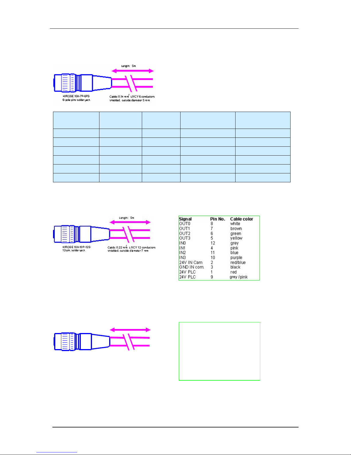
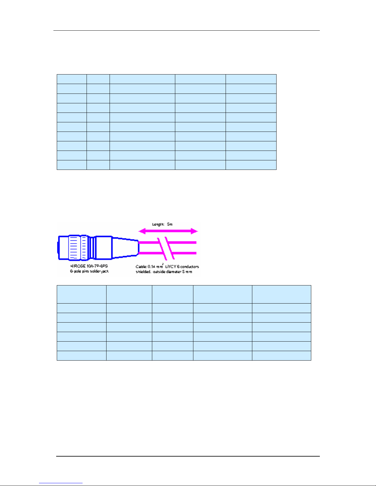
7.1 Trigger Cable
HIROSE 10A-7P- 6SC
6-pin. sol der plug
Length: 5m
Cable: 0.14mm LiYCY 6 conductors
shielded,
outside diam eter 5 mm
2
Signal
Pin Nr. Cable color
GND 3 white
+5V Out 2 brown
Trig. I n - 1 green
Trig. In+ 6 yellow
Trig. Out 5 grey
Keypad I n 4 pink
Equipped on one end with a Hirose plug, length 5m, 10m or 25m
7.2 RS232(V24) Cable
Equipped on one end with a Hirose plug, length 5m, 10m or 25m
Please order "with 2nd connector", if you need a DSUB9 connector at the other end
© 1996-2007 Vision Components GmbH Ettlingen, Germany VC20XX_HW.pdf
Page 33
VC20XX Operating Manual
29
7.3 Ethernet patch cable
Signal Pin (to cam.) Pin (to PC) Cable Color
20m patch cable
Cable Color
10m patch cable
T+ 2 1 yellow white/pink
T- 1 2 orange pink
R+ 6 3 white/green white/green
R- 5 6 green green
- 3 NC - -
- 4 NC - -
7.4 Power / PLC Cable
Equipped on one end with a Hirose plug jack, length 5m, 10m or 25m
7.5 SVGA Monitor Cable
HIROSE 10A- 10P-10P
10-pin. pins solder plug
Length: 5m
Cable: 5 x mini coaxial cable 75 Ohm
outside diam eter 7 mm
Signal
Pin No. Connection
R Out 4 red signal
R GND 3 red shield
G O ut 2 gr een signal
G G ND 1 green shield
B Out 9 blue signal
B GND 8 blue shield
HS Out 10 white signal
HS GND 7 whit e shield
V S Out 6 gray signal
VS GND 5
gray
shi eld
Equipped on one end with a Hirose plug, length 5m, 10m and 25m.
Please order "with 2nd connector", if you need an DSUB15 connector at the other end.
© 1996-2007 Vision Components GmbH Ettlingen, Germany VC20XX_HW.pdf
Page 34

VC20XX Operating Manual
30
7.6 Power adapter
input voltage 100 - 240VAC 50/60 Hz
output voltage DC 24 V +/-5%, max. 630 mA (15 W)
Equipped with 3 m connecting cable with a 12-pin Hirose plug, CE sticker
7.7 Power adapter for rail mounting
Input Voltage 100 - 240VAC 50/60 Hz
Output Voltage DC 24V +/-5%, max. 300 mA (7.5 W)
Equipped with connecting clamps for AC input and 24V output, CE certified
7.8 VC Keypad C6
VC Keypad includes the following keys:
- 4 cursor keys,
- Esc, Return,
- F1, F2 keys
TTL version, 3m cable equipped with 6 pin Hirose connector.
No additional power source required.
Note: The RS232 version of the keypad, used for VCXX cameras is NOT compatible!
7.9 Y-cable
Connectors:
1x HR10A-7P-6P 2x HR10A-7J-6S
Signal HR...6P / Pin Nr. cable color
1. HR10A-7J-6S
Pin Nr.
2. HR10-A7-J6S
Pin Nr.
GND 3 white 3 3
P5V 2 brown 2 2
Trig In 1 green 1 1
Trig InP 6 yellow 6 6
Trig Out 5 gray 5 5
RS IN 4 pink 4 4
© 1996-2007 Vision Components GmbH Ettlingen, Germany VC20XX_HW.pdf
Page 35

VC20XX Operating Manual
31
8 Connecting the Camera
• Connecting the camera power
• Single voltage, with or without PLC signals, no shutdown
• Dual voltage, with or without PLC signals, shutdown
• Connecting the RS232 Interface (n on Ethernet Versions)
• Connecting a compatible PC with a 9-pin D sub plug
• Connecting a compatible PC with a 25-pin D sub plug
• Connecting the Ethernet Cable (Ethernet Versions)
• Connecting the VC keypad
• Connecting the external trigger
Also consult the “VC20XX Installation Manual” available on the VC Website under:
“Support -> Customer Download Area -> Getting Started VC20XX Smart Cameras …”
8.1 Connecting the camera power
Power must be connected to the 12pin I/O connector. Note, that the voltage is 24V.
Camera power is regulated and galvanically separated inside the camera, so only an unregulated
power source of 24 V +/- 20% is required. The camera is, however, very sensitive to power supply
interruption. Please make sure, that the voltage never exceeds the limits of +/- 20% even for a short
period of time. In case of trouble it is recommended to backup the power supply by a capacitor or a
battery large enough to prevent power interruptions.
The camera has several internal circuits to detect and protocol power failures. Used correctly the
camera is even able to perform a correct shutdown and close all open buffers (see below). This
feature is for emergency only and is not designed to handle very frequent interruptions.
There are different options for the connection of the power supply:
• Single voltage, with or without PLC signals, no shutdown
• Dual voltage, with or without PLC signals, shutdown
For details refer to the following sections.
8.1.1 Single voltage, with or without PLC signals, no shutdown:
Signal Pin No. color connect to
24V IN Cam 2 red/blue 24V power supply
24V PLC 1 red 24V power supply
24V PLC 9 blue/pink 24V power supply
GND IN com. 3 black GND power supply
Pins 1 and 9 are are internally connected. Since one connector pin shows a maximum current
rating of 500mA, connect both pins if drawing higher currents from the PLC outputs!
This cabling option does not provide shutdown. Programmer must implement their own
procedures for fail-safe operation.
!
© 1996-2007 Vision Components GmbH Ettlingen, Germany VC20XX_HW.pdf
Page 36
VC20XX Operating Manual
32
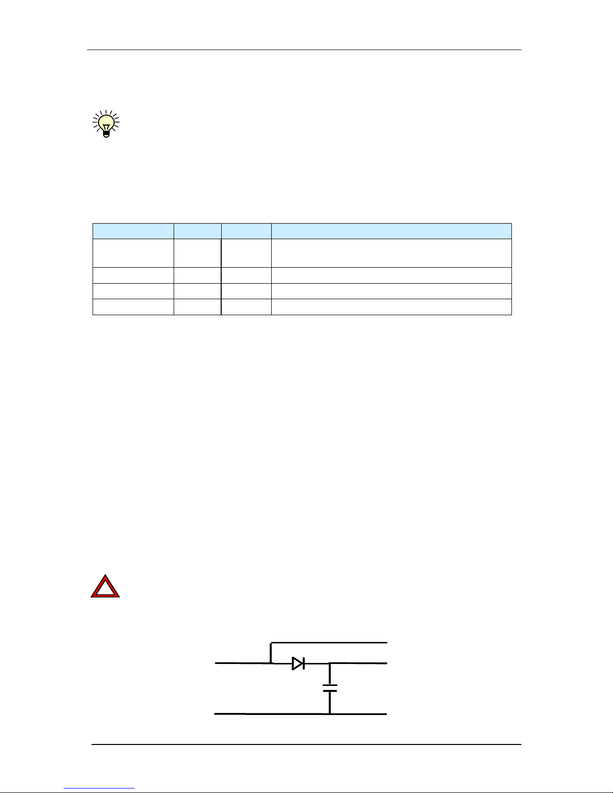
8.1.2 Shutdown Function for VC20XX Smart Cameras
VC20XX Smart Cameras incorporate a circuit to detect and protocol power failures. If the PLC
output power supply (12-24V PLC, Pin 1 and 9) of the cameras is interrupted, the system
variable “POWFAIL” is set to “1”. In case the PLC outputs are supplied, the status of
“POWFAIL” is “0” (refer to the sysvar.h).
This behaviour, that can also be checked using the shell command “ht”, can be used to perform a
controlled camera shutdown in case of a power failure.
Connecting the PLC/ Power interface for using this feature:
Signal Pin No. color connect to
24V IN Cam 2 red/blue
24V backup supply (supplying power at least 100ms
longer than grid supply in case of a power failure)
24V PLC 1 red 24V standard power (grid) supply
24V PLC 9 grey/pink 24V standard power (grid) supply
GND IN com. 3 black GND power supply
Here, the PLC voltage (24V PLC) is connected directly to the power (grid-) supply. The main camera
power supply at Pin 2 should remain high for at least 100ms longer than the power supplied to the
PLC supply. This can be done for instance with help of a suitable capacitor.
If a power failure occurs or if the main power supply is turned off, the camera detects this signal not
being present and the POWPLC status is changed from 0 to 1.
The system variable can be polled from time to time using the getvar(POWFAIL) function. This can be
best done using a background task.
The following procedures can be performed:
1. Stopping the operation of all programs and interrupts (no pictures will be taken any longer).
2. Saving all buffers (to multi-media card or flash EPROM).
3. Protocol time and date of the shutdown.
4. The procedure then waits for the backup voltage to disappear or main power to re-establish. If the
latter happens the program might be able to continue where it has stopped. (In this case there
may be some lost images = some parts not checked correctly)
Note that this feature is for emergency use only and is not designed to handle frequent
interruptions. The backup voltage must be able to supply the specified voltage for a period of
at least 100 msec (in addition to the polling delay).
!
24V PLC
GND
to ca mer a
24V PLC
GND
24V backup
from power supply
capacitor
10000µF
Sample Circuit for using the “power fail detect shutdown function”
© 1996-2007 Vision Components GmbH Ettlingen, Germany VC20XX_HW.pdf
Page 37
VC20XX Operating Manual
33
8.2 Connecting the RS232 Interface
8.2.1 Connecting a compatible PC with a 9-pin D sub plug
Pin (PC) Name cable color Pin (camera)
1 DCD Data Carrier Detect - / - - / 2 RxD Receive Data brown 2
3 TxD Transmit Data white 6
4 DTR Data Terminal Ready - / - - / 5 GND Ground gray 3
6 DSR Data Set Ready -/- - / 7 RTS Request to Send green 5
8 CTS Clear to Send yellow 1
9 RI Ring Indicator - / - - / -
Pink cable should alsways be left open
8.3 Connecting the Ethernet Cable
Signal Pin (to cam.) Pin (to PC)
Cable Color10/ 20m
patch cable
Cable Color
5m patch cable
T+ 2 1 yellow white/pink
T- 1 2 orange pink
R+ 6 3 white/green white/green
R- 5 6 green green
- 3 NC - -
- 4 NC - -
8.4 Connecting the VC keypad
The VC keypad C6 can be connected directly to the Trigger/Keypad ("Trig.") Plug.
Please order the 5V version (VC keypad C6) of the keypad.
For details see : VC Keypad C6
The RS232 version of the keypad is NOT compatible
© 1996-2007 Vision Components GmbH Ettlingen, Germany VC20XX_HW.pdf
Page 38

VC20XX Operating Manual
34
see Connecting the external trigger and the VC keypad
8.5 Connecting the external trigger
Connect the external trigger input/output directly to the Trigger/Keypad ("Trig.") Plug.
Please order "Trigger cable C6". Lengths available are 5m, 10m and 25m
For details see Trigger / Keypad Cable
see Connecting the external trigger and the VC keypad
8.6 Connecting the external trigger and the VC keypad
You may wish to connect both the keypad and the external trigger at the same time.
In this case you should use a special, short Y-cable with 1:1 connections of all the pins.
You may then proceed as mentioned in
Connecting the VC keypad
Connecting the external trigger
© 1996-2007 Vision Components GmbH Ettlingen, Germany VC20XX_HW.pdf
Page 39

VC20XX Operating Manual
35
9 Programming
The cameras are programmed in C with the aid of a cross development system. Any commercially
available PC can be used. The minimum required configuration is a Pentium, 4 MB of extended RAM
(8 MB recommended), Win98 or or higher, hard disk, VGA graphics, HD and mouse
The original cross development system supplied by Texas Instruments includes the following IDE
Code Composer Studio:
- ANSI C / C++ compiler
- C runtime library
- C source debugger
- TMS assembler
- TMS simulator
- Linker
- Librarian
- Project Manager
- numerous example programs
The following libraries and aids are also available:
- Real-time operating system for VC cameras with control of video I/O signals, control of
serial interface and of PLC I/O signals, file management system for flash EPROM and Multi
Media Card. (Ethernet Versions : Ethernet control by SW)
- In-circuit emulator
The emulator is connected to the parallel serial interface of a PC. The camera housing must
be opened and the emulator cable must be connected to the diagnosis plug of the camera.
The emulator supports debugging in C and assembly language.
- Standard image processing library
Filters (e.g. Sobel, Median, Laplace, 3x3, ...), imaging operations (addition, subtraction, etc.),
transformations (FFT, etc.) image averaging and noise filters, fast binary image processing
with run-length code (AND, OR, XOR, segmentation, morphological operations), feature
extraction (area, center of gravity, momentum, etc.), graphic functions and much more.
- JPEG image compression
compression and decompression of images according to JPEG standards
- Measurement library *)
Subpixel sampling, compensation of optical properties and diffraction effects, auto-focus, best
straight line, best circle
*) in preparation
© 1996-2007 Vision Components GmbH Ettlingen, Germany VC20XX_HW.pdf
Page 40
VC20XX Operating Manual
A
Appendix A: Blockdiagram VC20XX Smart Cameras
© 1996-2007 Vision Components GmbH Ettlingen, Germany VC20XX_HW.pdf
Page 41

VC20XX Operating Manual
B
Appendix B: Housing Dimensions VC20XX Smart Cameras
The housing of the VC2048 has 15mm deep cooling fins left and right of the camera body, making it
80mm wide.
© 1996-2007 Vision Components GmbH Ettlingen, Germany VC20XX_HW.pdf
Page 42

VC20XX Operating Manual
C
Appendix E: Drawing Camera Head VC40XX
© 1996-2007 Vision Components GmbH Ettlingen, Germany VC20XX_HW.pdf
Page 43

VC20XX Operating Manual
D
Appendix C: Spectral Transmission of IR Filter
Note:
This IR cut filter is incorporated in every VC20XX camera. The IR filter can be removed if
required without loosing Vision Component’s manufacturers warranty. In this case, special
care must be taken not to damage the CCD sensor.
If the camera is used without IR filter it is important to replace it by a clear glass filter of the
same size. The C-mount flangue distance from the CCD is accurately adjusted for the use of
the IR filter – removing the filter decreases the length of the optical path and it may become
impossible to focus some lenses to a larger working distance.
If the IR filter is not to be used, please order your camera with a clear glass filter or contact
Vision Components for obtaining a glass filter.
The order numbers for the clear glass filter is: EK000624
The order number for the IR cut filter (standard) is: EK000625
!
© 1996-2007 Vision Components GmbH Ettlingen, Germany VC20XX_HW.pdf
Page 44

VC20XX Operating Manual
E
Appendix D: CE Compliance of VC20XX Smart Cameras
The cameras are CE compliant. It certifies that numerous measurements were made provin g the
device complies with the appropriate EC regulations. Only electromagnetic compatibility was decisive
for this product.
This means that the cameras are not permitted to radiate electromagnetic waves in excess of a
boundary value layed down in the standard. They must also be insensitive to external radiation (e.g.
from cellular telephones). They must not be sensitive to static discharges, etc.
Unfortunately, it is not possible to limit the question of electromagnetic compatibility to just one device
or component. The entire system must always be considered.
Thus, the accessories such as cables, power supplies, etc., play a significant role for the VC series
cameras.
The manufacturer guarantees the boundary values for CE compliance only if the original accessories
are used.
CE Declaration of Compliance
The CE declaration of compliance for the VC20xx has the following wording. Corresponding
declarations also exist for the other camera models.
CE Declaration of Compliance
This certifies that the product designated as follows:
Machine Vision Camera Types
VC2028 / VC2038 / VC2038/E / VC2048/E,
VC2065/C, VC2065/EC, VC2065 / VC2065/E /
VC2066, VC2066/E, VC2068, VC2068/E
complies with the essential protection demands stipulated in the guideline on electromagnetic
compatibility of the Council for Harmonizing Legal Regulations of the Member States (89/336/EWG).
This declaration is valid for all examples manufactured according to the attached manufacturing
drawings, which are part of this declaration.
The following standards were utilized in judging the electromagnetic compatibility of this product:
EN 50081-2 : 1993
EN 50082-2 : 1993
This declaration is submitted by
Mr. Michael Engel, owner of the company named below
© 1996-2007 Vision Components GmbH Ettlingen, Germany VC20XX_HW.pdf
Page 45

VC20XX Operating Manual
F
for the manufacturer
Vision Components
Ottostr. 2
76275 Ettlingen
Karlsruhe, 01.11.2003 ..........................................
(legal signature)
Enclosures:
schematic diagrams
mechanical drawings (outside dimensions)
Records of tests conducted by the certified test laboratory
© 1996-2007 Vision Components GmbH Ettlingen, Germany VC20XX_HW.pdf
Page 46

VC20XX Operating Manual
G
INDEX
Accessories
Ethernet Cable 29
Keypad 30
Overview 28
Power Adapter 30
Power Cable 29
Rail Mount Power Adapter 30
RS232 Cable 28
Serial Cable 28
SVGA Monitor Cable 29
Y-cable 30
backup voltage 32
board
CPU Board 8
DAC Board 9
overview 5
Power Board 10
Sensor Board 5
cable
Ethernet 29
Powercable 29
RS232 28
Cable
Monitor Cable 29
Y-Cable 34
cable SVGA Cable 29
CE Decleration D
Connecting the Camera
Overview 31
Connection
Camera Power 31
Ethernet Cable 33
External trigger 34
External trigger AND keypad 34
VC Keypad 33
CPU Board 8
DAC Board 9
I/O-Plug
Plug Assignment 14
Input Signals 11
Keypad
Plug Assignment 14
Keypad C6 30
Output Signals 12
Overview
Accessories 28
8/E
Connecting the Camera 31
Patch Cable 29
PLC
Input Signals 11
Output Signals 12
Overview 11
Trigger Input 12
Trigger Output 12
Plug Assigment
Keypad 14
Overview 14
Trigger 14
Plug Assignment
I/O-Plug 14
RS232 15
Serial Interface 15
SVGA 15
Video Output 15
Power Adapter 30
Rail Mount 30
Power Board 10
Programming 35
Rail Mount Power Adapter 30
References II
RS232
Plug Assignment 15
RS232 cable 28
Sensor Board 5
Serial Interface
Plug Assignment 15
strcuture
basic 4
SVGA
Plug Assignment 15
technical specifications
overview 15
Technical Specifications
VC2028 16
VC2038 17
VC2038/E 18
VC2048/E 19
VC2065/EC 23
VC2066 24
VC2066/E 25
VC2068 26
VC206 27
© 1996-2007 Vision Components GmbH Ettlingen, Germany VC20XX_HW.pdf
Page 47

VC20XX Operating Manual
H
Trigger 12
Input 12
Output 12
Plug Assignment 14
VC2028
Technical Specifications 16
VC2038
Technical Specifications 17
VC2038/E
Technical Specifications 18
VC2048/E
Technical Specifications 19
VC2065/EC
Technical Specifications 23
VC2066
Technical Specifications 24
VC2066/E
Technical Specifications 25
VC2068
Technical Specifications 26
VC2068/E
Technical Specifications 27
Video Output
Plug Assignment 15
Y-cable 30
Y-Cable 34
© 1996-2007 Vision Components GmbH Ettlingen, Germany VC20XX_HW.pdf
Page 48

VC20XX Operating Manual
I
Visit the Vision Components site
www.vision-components.com for further information and
documentation and software downloads:
Web Site Menu Links Content
Contact
Distributor list / Enquiry forms
Home
Latest News from VC
Our Company
VC Company Information
News and Events
Trade Show dates
VC Publications
Sign in for free VC Seminars
VC Network
Description of Partner Companies
Application Overview
3
rd
Party Hard- and SW Products for VC Smart
Cameras
Products
VC Smart Camera Overview
Product Overview:
VC44XX High End Camera Series
VC40XX Standard Camera Series
VC4016 / 18 Entry Level Cameras
VC4002L Line Scan Camera
VCSBC Single Board Cameras
VC20XX Smart Cameras
VCSBC Board Cameras
VCM + Viscube Camera Sensors
VC Smart Camera Software
VC Software Development Kit Ti: VCRT Operating System
VCLIB Image Processing Library
VC Special Libraries: M200 D ata Matrix Code Reader
VCOCR Text Recognition Library
Color Lib
Support:
Support News (User Registration required) Tech News – new SW and Documentation
Knowledge Base / FAQ (User Registration
required)
Searchable FAQ Database with programming
Examples and Demo Code
Download Area Download of:
Public Download Area
(free Access)
- Product Brochures
- Camera Manuals
Registered User Area
(User Registration required)
-
Getting Started
- Programming Manuals
- Training Manuals and Demo Code
Customer Download Area
(User- and SW License
Registration required)
- Software Updates
- Demo Code
RMA Number Form Form for Allocation of Repair Numbers.
© 1996-2007 Vision Components GmbH Ettlingen, Germany VC20XX_HW.pdf
 Loading...