

Page 1

R
R
Installations- und Betriebsanleitung
GERMANY
C
C
GERMANY
By selecting this VC product you have chosen a professional
device, which guarantees highest possible quality and
Please read the following instructions carefully before
comissioning the product in order to be able to take full
advantage of all quality features regarding this product line.
Mounting and Operating Manual
Dear Customer!
reliability.
Digit al Video Recorder
Art. Nr. 12780-CHR
with CD-RW
© 2007 All contents of this document may change without prior notice
Änderungen in T echnik, Design und Ausst attung vorbehalten
VC-videocomponents.... aligned for professional videosystems
IB_12780-CHR / 19.11.2007
IB_12760-OHR
Page 2

Page 3

•••• Contents
Contents
ContentsContents
•••• Chapter 1.
Chapter 1. Specification & System organization
Chapter 1. Chapter 1.
1. Product Contents List -------------------------------------------------------- 3
2. System Organization --------------------------------------------------------- 4
• Chapter 2. Product Description
Chapter 2. Product Description
Chapter 2. Product DescriptionChapter 2. Product Description
1. AVR-1612 / 812 Front Panel --------------------------------------------------- 5
2. AVR-1612/812 Rear Panel --------------- - - --------------------------------- 7
3. AVR-412 Front Panel- - - - - - - - - - - - - - - - - - - - - - - - - - - - - - - - - - - - - - - - - - - - - - - - - - - - - 8
4. AVR-412 Rear Panel ---------------------------------- ---------------------- 9
5. Remote Controller --- - - -- - - -- - - - - --- - - - - ---- - - - - - - --- - - - - ---- - - - - - --- - - - - - 10
Specification & System organization
Specification & System organizationSpecification & System organization
•••• Chapter 3.
Chapter 3. Display
Chapter 3. Chapter 3.
1. System Power ON ---------------------------------------------------------- 11
2. Screen View Selection -------------- ---------------------------------------- 12
3.Display Mode - - - - - - - - - - - - - - - - - - - - - - - - - - - - - - - - - - - - - - - - - - - - - - - - 12
4. PTZ/FOCUS Control -------------------------------------- ------------------ 13
5. System Power OFF --------------------------------------------------------- 13
•••• Charpter
Charpter 4.
CharpterCharpter
Go to Search Mode ----------- ---- ------------------------------------------ 14
1. Search by Date/Time ---------- --------------------------------------------- 14
2. Search by Event ----------------------------------------------------------- 15
Display
DisplayDisplay
4. Search
Search
4. 4.
SearchSearch
1
Page 4

•••• INDEX
•••• Chapter 5. SETUP
Chapter 5. SETUP
Chapter 5. SETUPChapter 5. SETUP
Go to Menu -------------------------------------------------------------- 16
Go to System Setup ----------------------------- --------------------------- 16
1. Display ------------------------------------------------------------------ 17
2. Camera ----------------------------------------------------------------- 21
3. Sound ------------------------------------------------------------------ 22
4. System ------------------------------------------------------------------ 25
5. Event/Sensor ------------------------------------------------------------- 30
6. Disk Management ---------------------------------------------------------- 31
Go to Record Menu --------- -------------------- --------------------------- 34
1. Recording Operation ----------------------------------- --------------------- 34
2.Timer/motion setup -- - - - - - - - - - - - - - - - - - - - - - - - - - - - - - - - - - - - - - - - - - - - - 35
3. Alarm Record Schedule ----------------------------------- ------------------ 34
4. Panic setup ------- - - ---- - - --- - - - --- - - ---- - - --- - - - --- - - --- - - - --- - - - 37
Go to Archiving ----------------------- --------------------------------- --- 38
1. CD-RW and USB Back up ------- --- --------------------------------------- -- 38
• IMPORTANT SAFETY INSTRUCTIONS ---- - -- - -- - - -- - - - - - - - -- - -- - -- - -- - -- - -- - -- - -40
2
Page 5
1. Specification & Organization
1. Product contents List
1. Product contents List
1. Product contents List1. Product contents List
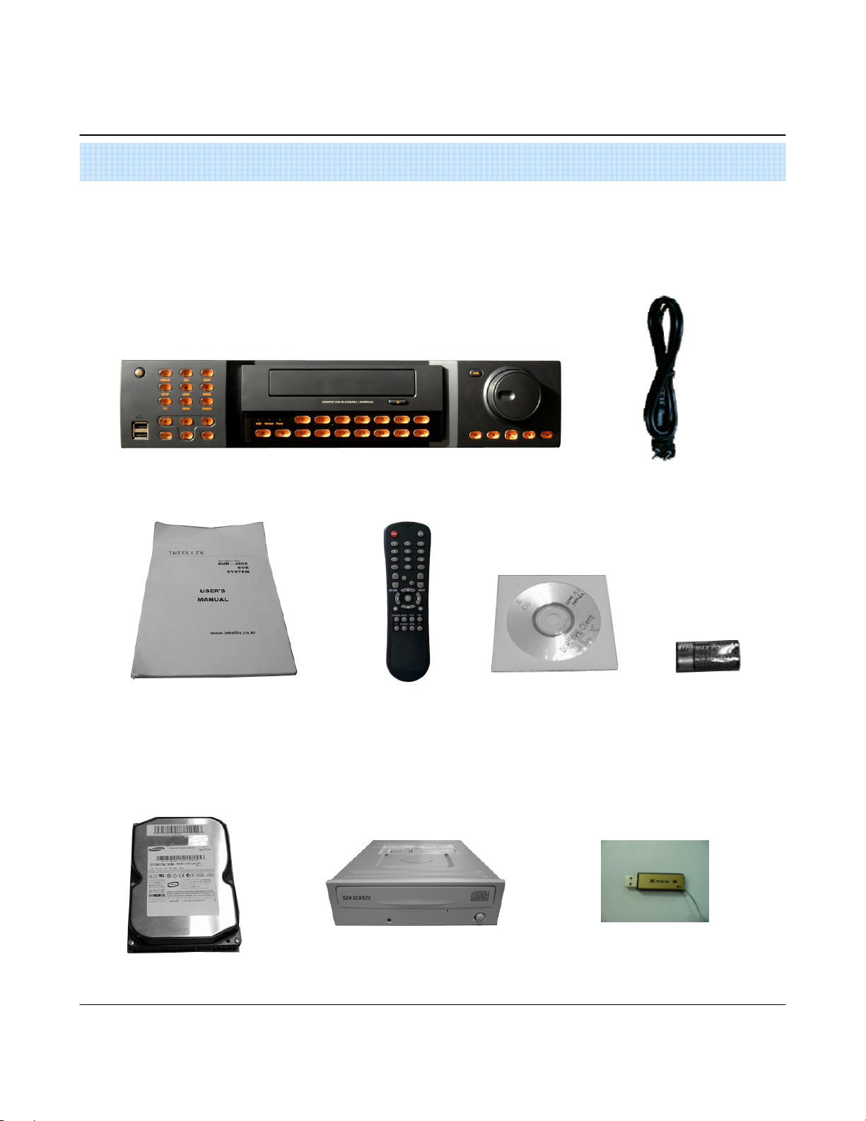
Please Confirm the Contents When open Package.
Basic Contents
Basic Contents
Basic ContentsBasic Contents
Power Cable
Option Contents
Option Contents
Option ContentsOption Contents
HDD
User’s Manual
Remote Controller
CD-RW USB Memory
3
Remote Client Program
Install CD
AAA Battery X 2
Page 6
1. Specification & Organization
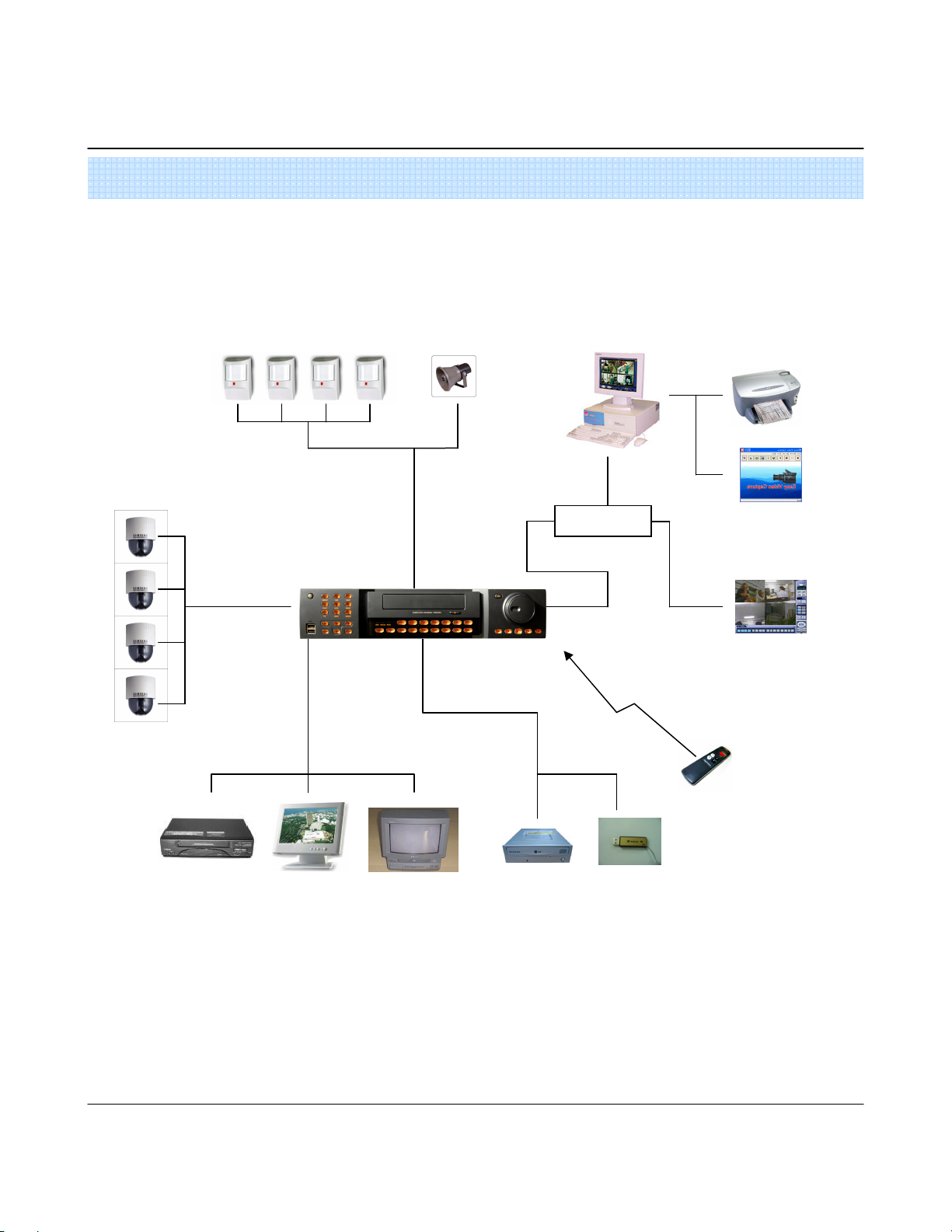
2. System Organization
2. System Organization
2. System Organization2. System Organization
Camera #1-8(16)
Alarm Sensor #1-8(16) Relay Out
Alarm Input/Out
Video In
Video Out
TCP/IP
Backup
Remote Client PC Image Printer
NETWORK
NETWORK
NETWORKNETWORK
AVI Backup
WEB Client
VCR
VGA
Monitor
AV Monitor
Remote
Controller
USB
CD-RW
(It is not supported at the AVR-400SX)
4
Page 7
2. Description(8,16CH)
1. Front Panel
1. Front Panel
1. Front Panel1. Front Panel
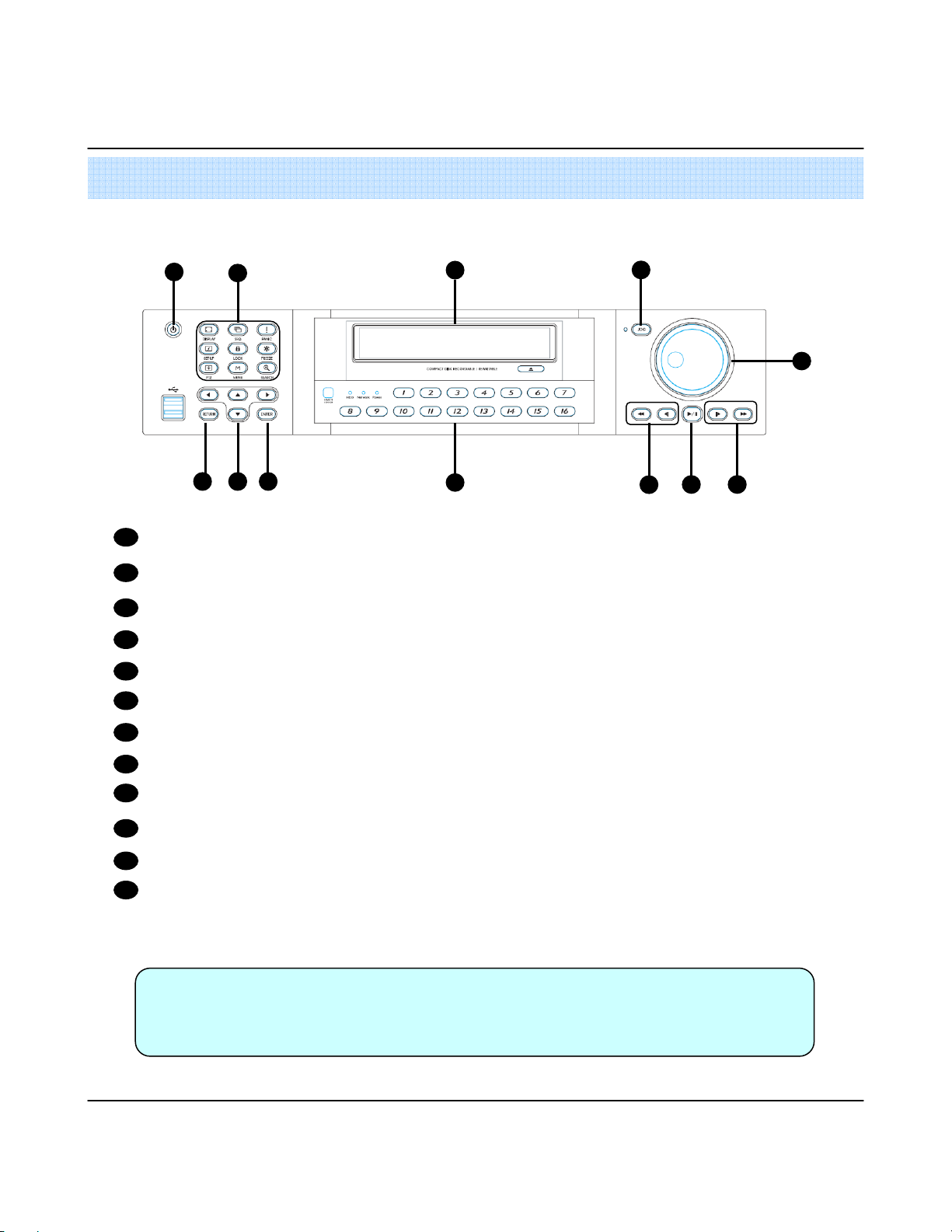
1
1
POWER
POWER : System Power On/Off
POWERPOWER
2
SHORTCUT
SHORTCUT : Shortcut button for convenience.
SHORTCUT SHORTCUT
CD/DVD RW :
CD/DVD RW : Back up image to CD/DVD RW
CD/DVD RW : CD/DVD RW :
3
HOLD :
HOLD : Hold Current Jog/Shuttle position
HOLD : HOLD :
4
RETURN
RETURN : Cancel/Deselect/Return to previous screen
RETURNRETURN
5
6
Direction / Navigation Button :
Direction / Navigation Button : UP/DOWN/LEFT/RIGHT
Direction / Navigation Button : Direction / Navigation Button :
2
765
3
8
4
12
11
10
9
7
ENTER
ENTER : Confirm/ Select next screen
ENTERENTER
8
CHANNEL
CHANNEL Select
CHANNELCHANNEL
9
FOCUS
FOCUS : Adjust Focus (Near/ Far) or Reverse Play /Rewind
FOCUSFOCUS
PAUSE
PAUSE : Pause playback
PAUSEPAUSE
10
IRIS
IRIS : Adjust Iris (Open/Close) or Forward Play / Fast forward
IRISIRIS
11
12
Jog shuttle :
Jog shuttle : Outer wheel – variable REW or FF : Inner wheel – scroll frame – by frame while paused
Jog shuttle : Jog shuttle :
Tip
Tip
TipTip
Select button
button : Select Channel or Input Password.
SelectSelect
buttonbutton
•Channel Selection Button is Prior to DISPLAY.
• When Remote Controller Sensor Input is Blocked by Something, it Cause 1 Remote Controller
do NOT Work Properly.
• When Press any Button, it Operate with Beep Sound.
5
Page 8
2. Description
* Shortcut button
* Shortcut button
* Shortcut button* Shortcut button
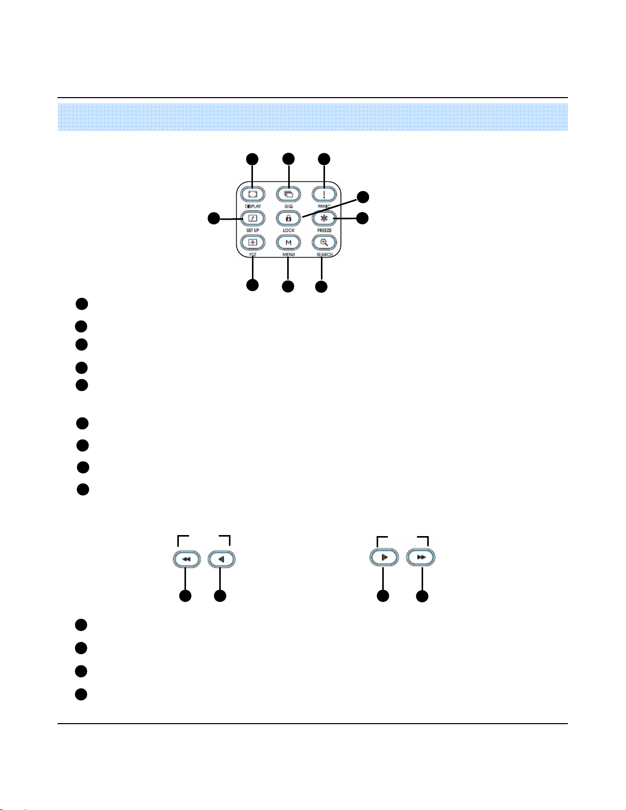
1
2
3
5
4
7
1
DISPLAY
DISPLAY : Select Screen Division Mode or Rotation Mode.
DISPLAYDISPLAY
SEQ
SEQ : Select sequence screen mode.
SEQSEQ
2
3
PANIC
PANIC : Urgent Recording as setup.
PANICPANIC
ZOOM
ZOOM : Digital zoom on Live or Playback image
ZOOMZOOM
4
5
LOCK
LOCK: Front Panel Lock Button (Default password: 1234)
LOCKLOCK
When locked, “LOCK”is displayed on screen. Press lock button to unlock.
6
ARCHIVE
ARCHIVE : Go to archiving setup menu. (Default password : 1234)
ARCHIVEARCHIVE
7
PTZ
PTZ: Go to Camera PTZ Control.
PTZPTZ
SETUP
SETUP : Go to System Setup.
8
SETUPSETUP
SEARCH
SEARCH : Go to Search Mode.
SEARCHSEARCH
9
(Default password: 1234)
(Default password: 1234)(Default password: 1234)
(Default password : 1234)
(Default password : 1234)(Default password : 1234)
8
6
9
* FOCUS / IRIS button
* FOCUS / IRIS button
* FOCUS / IRIS button* FOCUS / IRIS button
NEAR :
NEAR : Set camera focus (Near & Far) or Reverse Play/Rewind.
NEAR : NEAR :
1
FAR :
FAR : Set camera focus far.
FAR : FAR :
2
CLOSE :
CLOSE : Close camera iris.
CLOSE : CLOSE :
3
OPEN :
OPEN : Open camera iris.
OPEN : OPEN :
4
FOCUS
FOCUS
FOCUSFOCUS
1 2 3
6
IRIS
IRIS
IRISIRIS
4
Page 9
2. Description
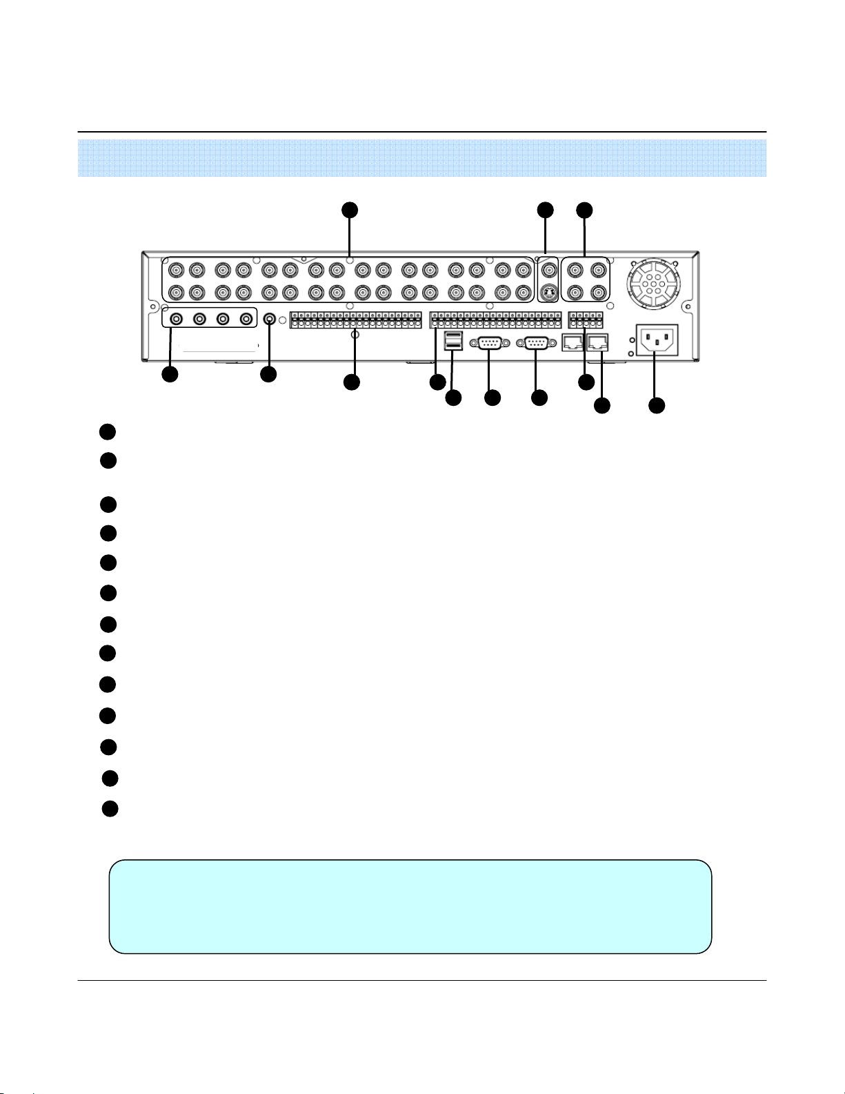
2. Rear Panel
2. Rear Panel
2. Rear Panel2. Rear Panel
1 2
3
4
Video IN / Loop :
Video IN / Loop : BNC Video Input Port/ Loop Output (1-8/16)
Video IN / Loop : Video IN / Loop :
1
Monitor out :
Monitor out : BNC Main Monitor Output.
Monitor out : Monitor out :
2
SVHS
SVHS : S-Video Main Monitor Output.
SVHSSVHS
Spot #1 ~ #4 :
Spot #1 ~ #4 : 4x BNC Output to individually – Sequenced Spot Monitors
Spot #1 ~ #4 : Spot #1 ~ #4 :
3
Audio In :
Audio In : 4 x RCA Audio Line Input Terminal
Audio In : Audio In :
4
Audio Out :
Audio Out : RCA Audio Line Out Terminal
Audio Out : Audio Out :
5
Alarm
Alarm : 8/16 x Input TTL Alarm/Sensor Input Terminal
AlarmAlarm
6
Relay
Relay : 8/16 x Relay Output Terminal
RelayRelay
7
USB :
USB : USB port for use the USB memory stick and USB HDD Backup.
USB : USB :
8
VGA OUT
VGA OUT : VGA Main Monitor Output (to a computer Monitor)
VGA OUTVGA OUT
9
RS
RS----232C
232C : Serial Configuration Port for Program Debugging.
RSRS
10
11
232C232C
RS
RS----485
485 : Serial Interface for PTZ device connection and control
RSRS
485485
5
76
98 10
11
12
13
Ethernet (TCP/IP)
Ethernet (TCP/IP) : 10/ 100 Ethernet LAN/WAN connection (for Remote Access and configuration)
Ethernet (TCP/IP)Ethernet (TCP/IP)
12
POWER :
POWER : Power Cable connection.
POWER : POWER :
13
•Do not power on the unit all cable connections have been made.
Tip
Tip
TipTip
7
Page 10
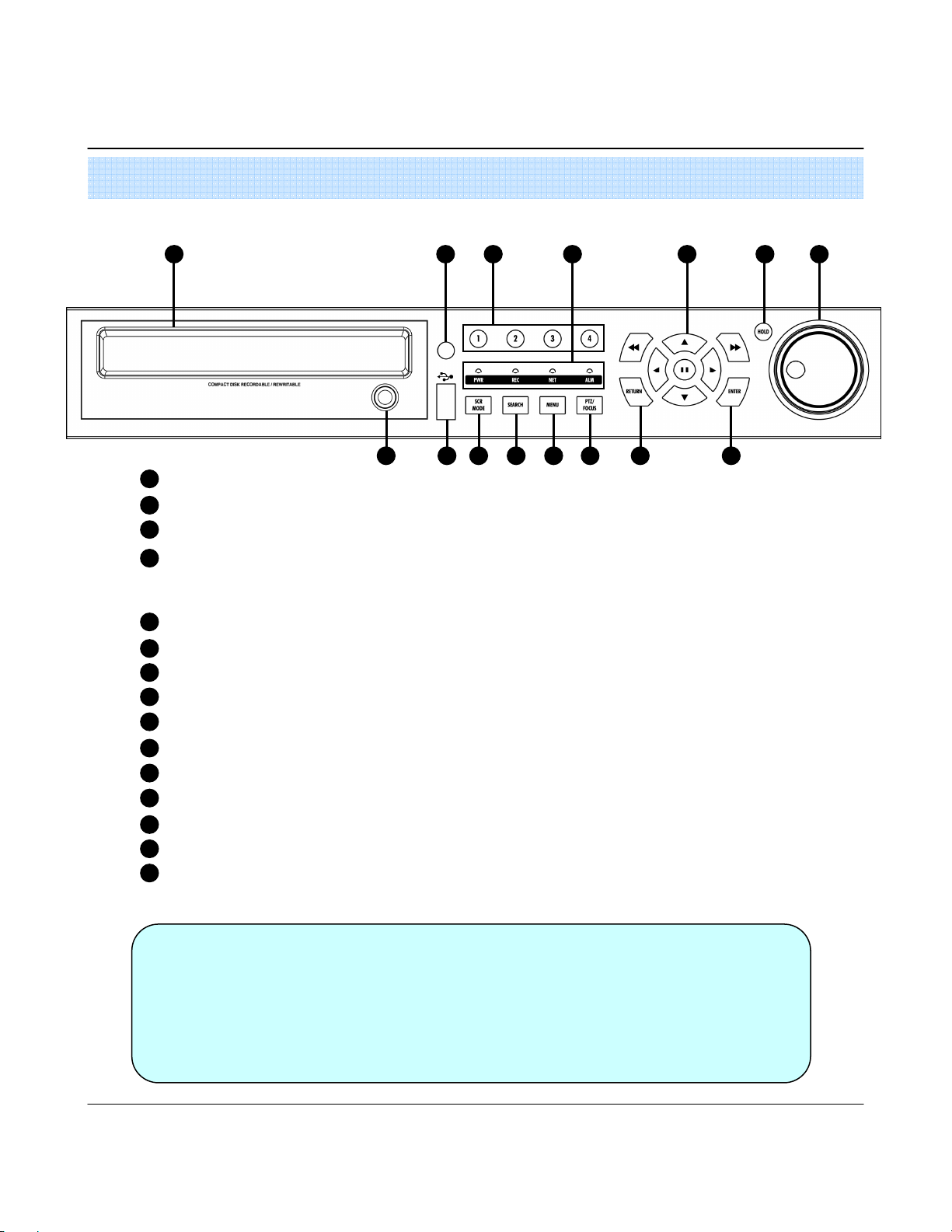
2. Description (4CH)
1. Front Panel
1. Front Panel
1. Front Panel 1. Front Panel
1 2 3 4 765
1
CD-RW : CD-RW Device for Backup.
Remote Controller Sensor Input.
2
3
Channel Selection Button : Select Channel or Input Password.
Led Indicator : Indicate Present System Status Information.
4
( POWER: System On/Off , RECORD: Record On/Off ,
NETWORK: Client Network Connection Status, ALARM: Alarm Sensor Detection Status )
5
Search Controller: Searching Recorded Data or Control Menu & PTZ/FOCUS.
HOLD : Hold Jog dial.
6
JOG dial
7
8
Eject : Eject CD
9
USB Port: USB port for use the USB memory stick and USB HDD Backup
SCR MODE : Select Screen Division Mode or Rotation Mode.
10
SEARCH : Go to Search Mode for Searching Data.
11
MENU : Go to System Menu.
12
PTZ/FOCUS : Go to Camera PTZ/FOCUS Control.
13
RETURN : Cancel Setup or Return to Previous Mode.
14
ENTER : Apply Changing Setup.
15
11 1298 10 13 14 15
Tip
Tip
TipTip
•Channel Selection Button is Prior to SCR Mode.
• When Remote Controller Sensor Input is Blocked by Something, it Cause 1
Remote Controller do NOT Work Properly.
• When Press any Button, it Operate with Beep Sound.
• In Case of CD-RW, the Real Appearance will be Differ from the above Picture 1
Depends on its Model.
8
Page 11
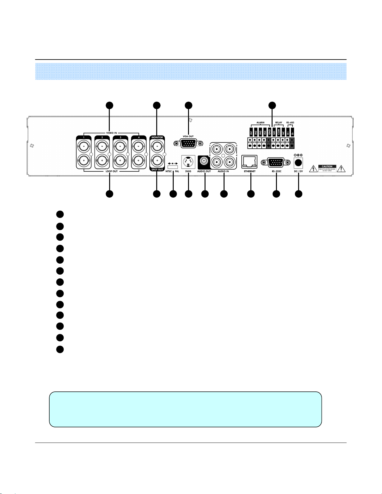
2. Description
2. Rear Panel
2. Rear Panel
2. Rear Panel2. Rear Panel
1 3 6 11
2 4 75 1298 10 13
1
Video In : BNC Port for Connection of DVR & Camera. (4 Camera Connectable)
Loop Back : Output DVR Camera Video to Loop Back Port. (4 BNC Port)
2
Monitor Out : Output DVR Video to AV Monitor.
3
Spot Out : Output Spot-out Video to AV Monitor.
4
NTSC/PAL : Select NTSC or PAL Type.
5
VGA OUT : Output Video to a Computer Monitor by Connected VGA (Option)
6
SVHS : Output Video by Connected SVHS.
7
Audio Out : Output Audio Data.
8
Audio In : Audio Input Terminal Related with #1~4 Camera.
9
10
Ethernet (TCP/IP) : Port for Cross cable. (Possible to Remote Surveillance.)
11
Alarm/Relay/RS-485 : Connect Port for Sensor, Relay, & PTZ.
12
RS-232C : Connect Port for Program Debug.
DC Power Input : Power Supply by DC 12V Adaptor.
13
Tip
Tip
TipTip
• When System Installation, Please Install under System Power Off Status.
•Please Use Specific Adaptor when Power Supply.
9
Page 12
2. Description
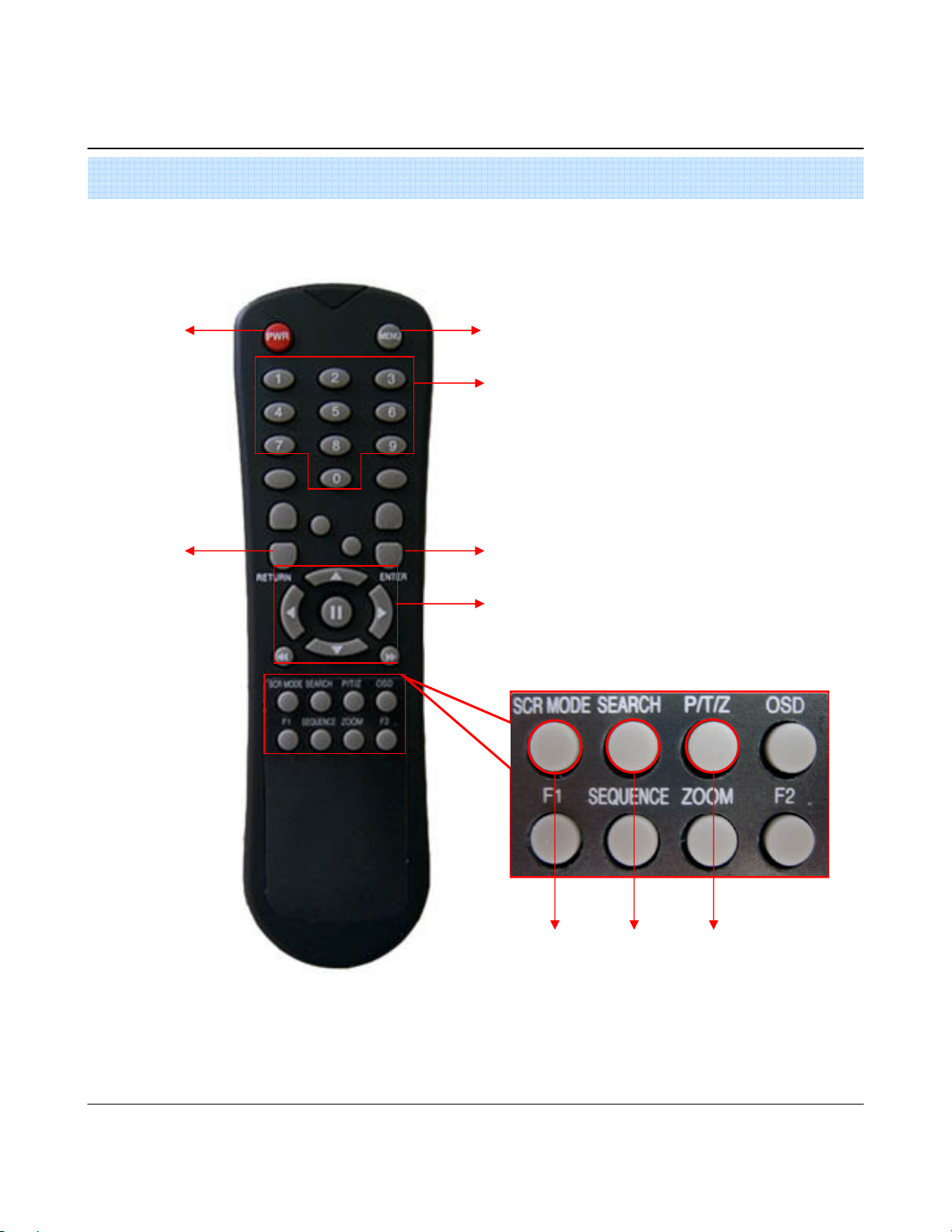
3. Remote Controller
3. Remote Controller
3. Remote Controller3. Remote Controller
POWER
POWER
POWERPOWER
System
ON/OFF
RETURN
RETURN
RETURNRETURN
Cancel / Deselect
Previous Screen
MENU
MENU : Open System Setup Menu
MENUMENU
Channel Selection Buttons
ENTER
ENTER : Apply / Select /Go to Next Sereen
ENTERENTER
Navigation Buttons
Navigation Buttons : Used for Playback Control, Menu
Navigation ButtonsNavigation Buttons
Navigation, and PTZ/Focus Control
Change Display
Mode
•There are buttons on the controller that are unused, and their descriptions have been omitted.
•Every Button on the controller will function the same as its corresponding button on the Front Panel
• Remote Controller will only work when used within line-of-sight of the IR remote sensor on the DVR.
If there are many DVRs within line-of-sight of the controller, they will all respond to the controller.
Search Menu
10
PTZ/IRIS Mode
Page 13
3. Display
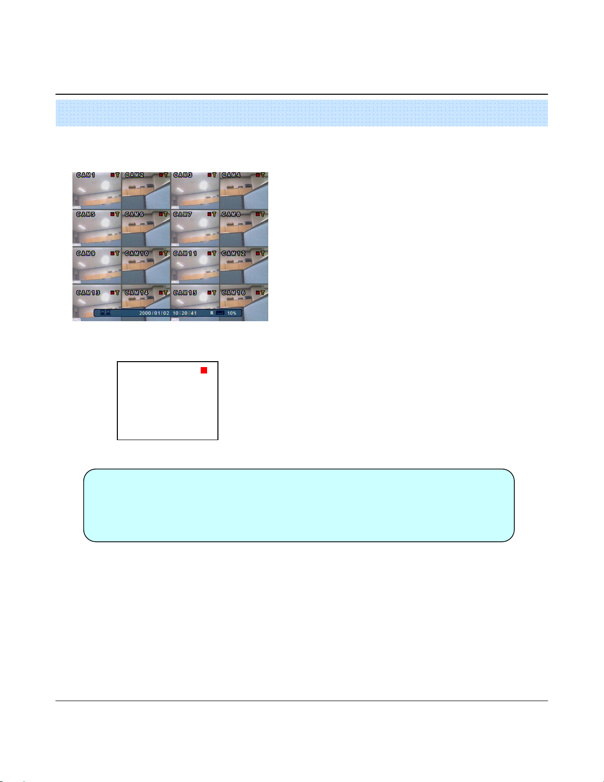
1. System Power ON
1. System Power ON
1. System Power ON1. System Power ON
<Picture of Power On after Finishing Installation>
CAMERA
•Press power button to start system.
•After Checking Hard Disk, display mode is shown.1
•Initial Screen View Mode is Quad Division Mode and Recording Mode.
•Each Channel Indicates Camera Name & Recording Status.
•Present Time & Date shown on Status Bar at a bottom of screen.
Tip
Tip
TipTip
2005/01/01
00:00:00
•Check System status LEDs
Power : Indicates System (On/Off)
Record : Indicates Recording (On/Off)
Network : Indicates Network/LAN Client connection Status
11
Page 14
3. Display
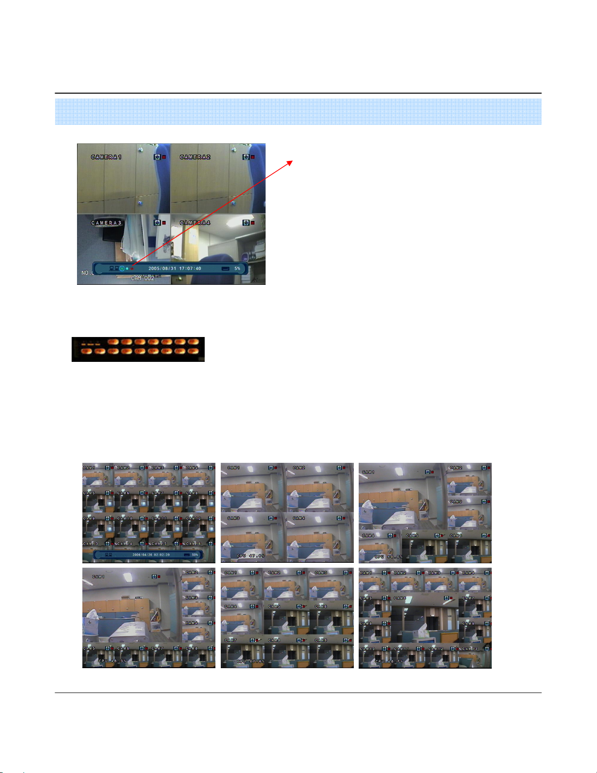
2. Screen View Selection
2. Screen View Selection
2. Screen View Selection2. Screen View Selection
When this unit is connected with a remote client PC, a
Network status icon will appear on the Status Bar
•This icon indicates the current network conditions
- Green: Network is connected and stable.
- Blue: Network is connected, but is unstable.
- Red: Network is very unstable.
•Select One Channel using the channel selection buttons (1-8/16).
• Use the display button to change the multi-channel Display mode.
•Press channel selection button twice to view the channel on full screen.
3. Display Mode
3. Display Mode
3. Display Mode3. Display Mode
• User can select from a variety of multi-screen display modes (1/4/6/8/9/13/16ch)
•The initial display mode is set to either 8ch or 16ch mode.
12
Page 15

3. Display
4. PTZ/FOCUS Control
4. PTZ/FOCUS Control
4. PTZ/FOCUS Control4. PTZ/FOCUS Control
•Control Camera Movement of PTZ (Pan/Tilt/Zoom) devices.
•Press PTZ Button to switch into PTZ mode. (Status Bar is replaced by PTZ controls)
•Each PTZ function is manipulated by using a button on the Front Panel or on the Remote controller.
•Some of the notations on the PTZ menu are abbreviated. (P: Pan, T: Tilt, Z: Zoom, F: Focus, I: Iris)
•All of the functions on the PTZ menu are labeled along with the Front Panel/ Controller button that control it.
5. System Power Off
5. System Power Off
5. System Power Off5. System Power Off
•System Log-On User Account Types are ‘Administrator’, ‘Manager’, ‘User’
Tip
Tip
TipTip
Administrator: Access All Function (Power On, Shutdown, Setup, Search, Backup)
Manager: System Power On, Live View, Search, Playback
User: System Power on and Live View
•Press power button to power system off.
•Input password and press enter to shutdown system.
•Don’t disconnect AC power without completing shutdown.
13
Page 16
4. Search
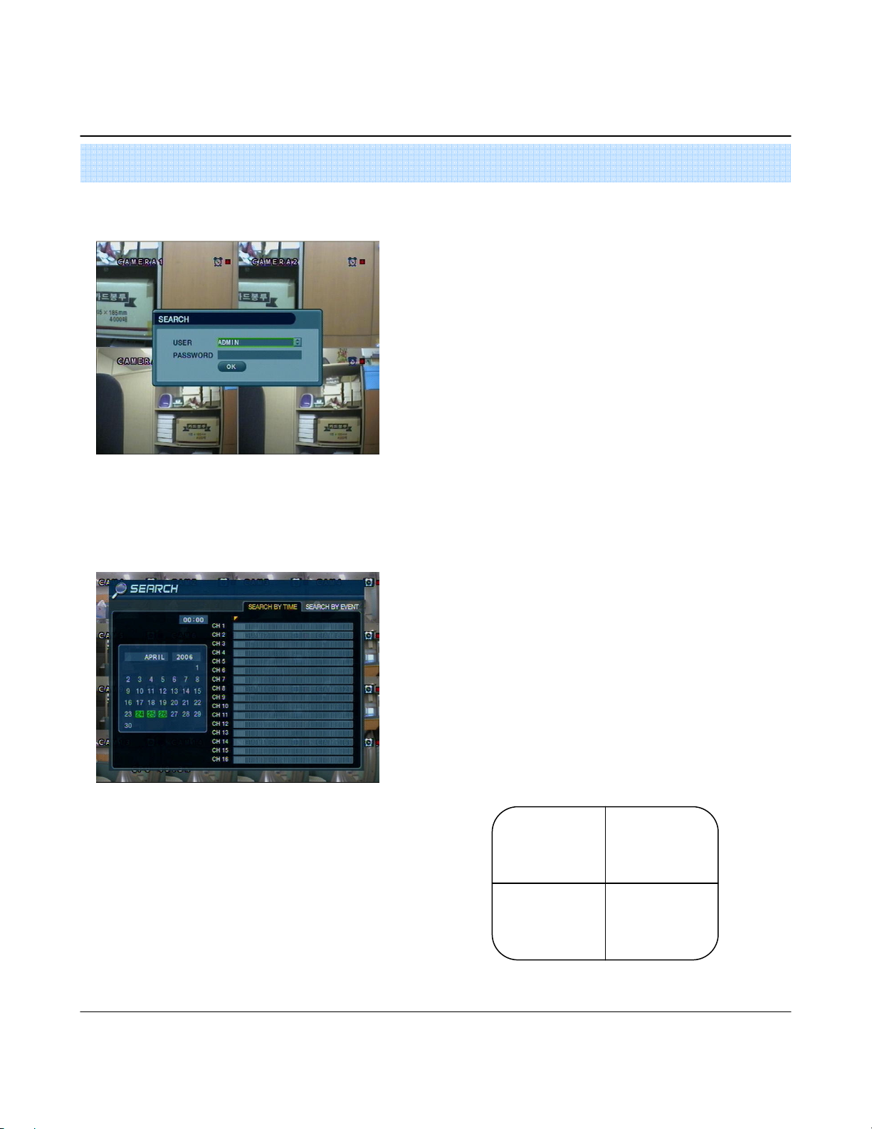
Go to Search Mode
Go to Search Mode
Go to Search ModeGo to Search Mode
1. Search by Time
1. Search by Time
1. Search by Time1. Search by Time
- Search by a recorded Date/ Time
•Press search button and Log-In.
(as administrator or manager )
• Use directional keys to navigate search menu.
•To open/ advance each sub menu, Press enter
•To return to a previous menu screen, Press return.
( Repeatedly pressing return will exit out of all menus.)
•The recorded date & time is shown on the status bar.
•The current playback mode (Play, Pause, FF, REW)
is indicated with on icon on the bottom-right of the screen.
• The channel selection and display buttons will work the
same as in live view mode, setup, PTZ and archiving
buttons don’t work in the playback mode.
Move cursor to select the date on the calendar.
Press enter to open selected date.
Recorded timeline will appear.
Move cursor to the specific time, and press enter. (The timeline
is divided into 15 minutes segments)
Menu will be hidden from view, and playback will
start playing from the selected date/ time forward.
2004/01/01
00:00:00
>
14
Page 17
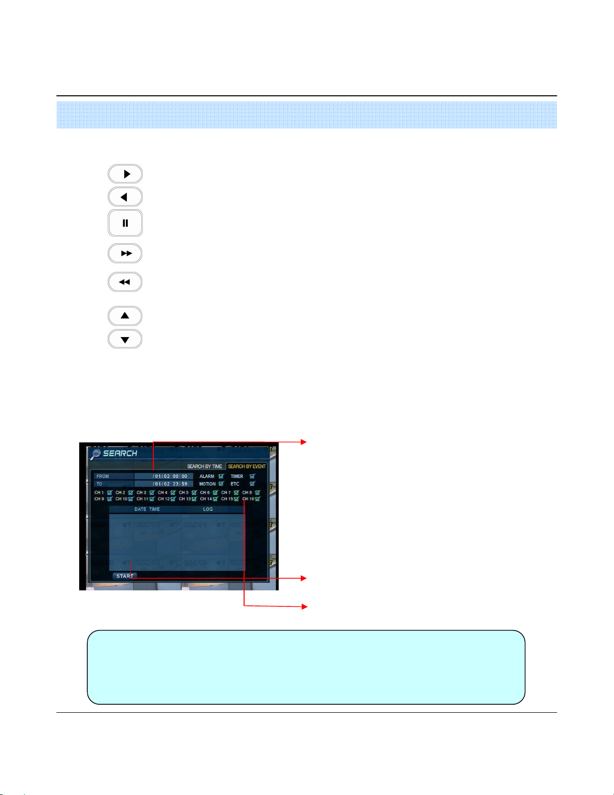
4. Search
•Video Playback Controls
: Basic playback mode (Normal speed (1X) forward playing)
: Normal speed (1x) backward playing
: Pause playback (Enable the JOG wheel)
: Fast forward (2x ~ 64x speed)
: Fast rewind (2x ~ 64x speed)
: Variable FF/REW Speed, same as #
Use JOG or press normal forward/backward button while paused, to advance previous/next frame.
2. Search by Event
2. Search by Event
2. Search by Event2. Search by Event
- Search Video with based on alarm/sensor events, motion recording events and system events
Tip
Tip
TipTip
Select start date & end date of the event search.
Alarm : Search alarm/sensor events within the selected
date/time period.
Motion : Search for motion recording events within the
selected period
Timer : Search for schedule change or recording setup
change events with the selected period.
System : Search for power on/off events or other system
events within the selected period
Event search results display in the lower window
Channel selection : choose the channels to search
•Alarm, Motion, System can be selected at the same time by checking the checkbox next
to each of the desired options (V)-(ENTER)
•To change Date/ Time selection, Press enter and use the directional keys to
Increase or decrease the value. When desired value is set, Press enter.
15
Page 18
5. Setup
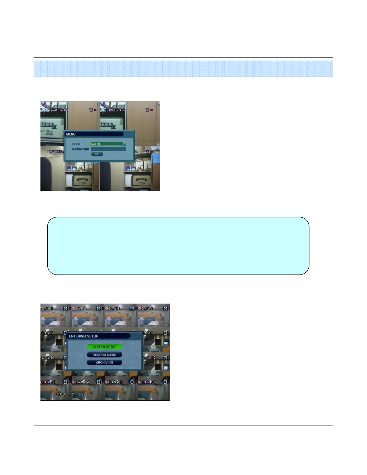
Go to setup
Go to setup
Go to setupGo to setup
Tip
Tip
TipTip
Press setup button.
Unit will ask for login/password Entry.
Input password using by channel selection button.
After login, select a submenu and press enter.
•The Initial password for the Admin account is 1234.
• On-Screen display will show the password digit as : ****
•To set up or edit user accounts, or Login/ Password information, go to
System setup->System -> User management submenu.
•You may only enter into the setup menu from live view mode.
Go to System setup
Go to System setup
Go to System setupGo to System setup
•Choose “ System Setup” to enter into the setup menu.
16
Page 19
5. Setup
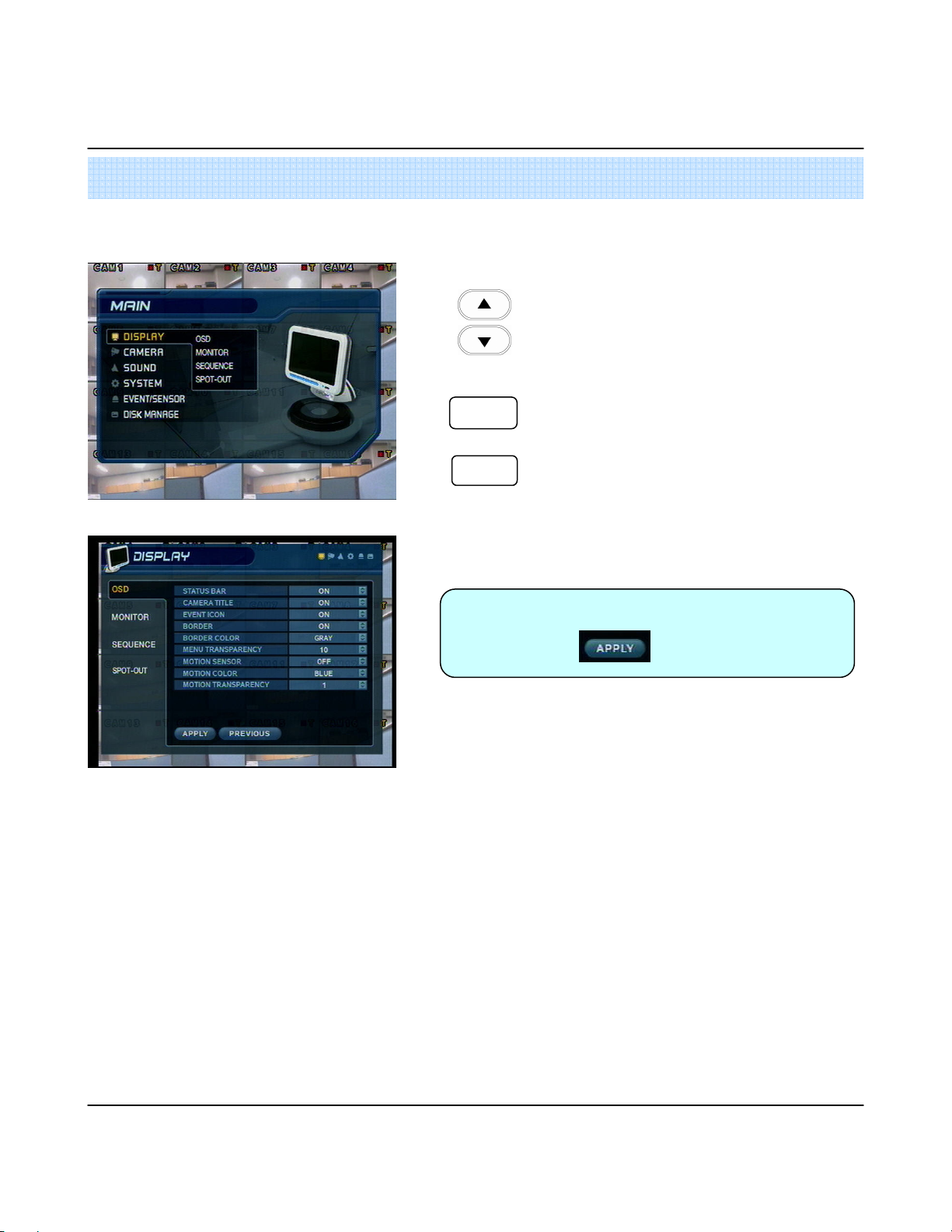
1.Display
1.Display
1.Display 1.Display
- Allows configuration of display properties
•Live view display options are edited within this submenu.
1111----1. OSD
1. OSD
1. OSD1. OSD
•
•
•
ENTER
ENTER
ENTERENTER
RETURN
RETURN
RETURNRETURN
Tip
Tip
TipTip
Navigate menu by using directional buttons
Select the desired menu category and press “ Enter”
Return to previous menu (or live view mode)
• When have finished changing settings,
Press to confirm the changes.
•Status Bar : Recording mode icon (on/off), (Recording: Red, Pre-recording : Green)
•Camera Title: Show/Hide camera name (on/off).
•Event Icon: Show/Hide event icon (on/off).
•Border : Show/Hide border Grid (on/off) in multi-channel mode.
•Border Color : Select color of border Grid. (White, Blue, Red, Yellow, Green, Gray)
• Menu transparency : Setup menu transparency.
• Motion Sensor : Toggle Motion Detection (Off/Active / Inactive)
- Active : Display motion sensor of motion detection area.
- Inactive : Display motion sensor except motion detection area.
- Off : No display of motion sensor.
• Motion sensor color : Setup motion sensor color.
• Motion transparency : Setup motion transparency.
17
Page 20
5. Setup
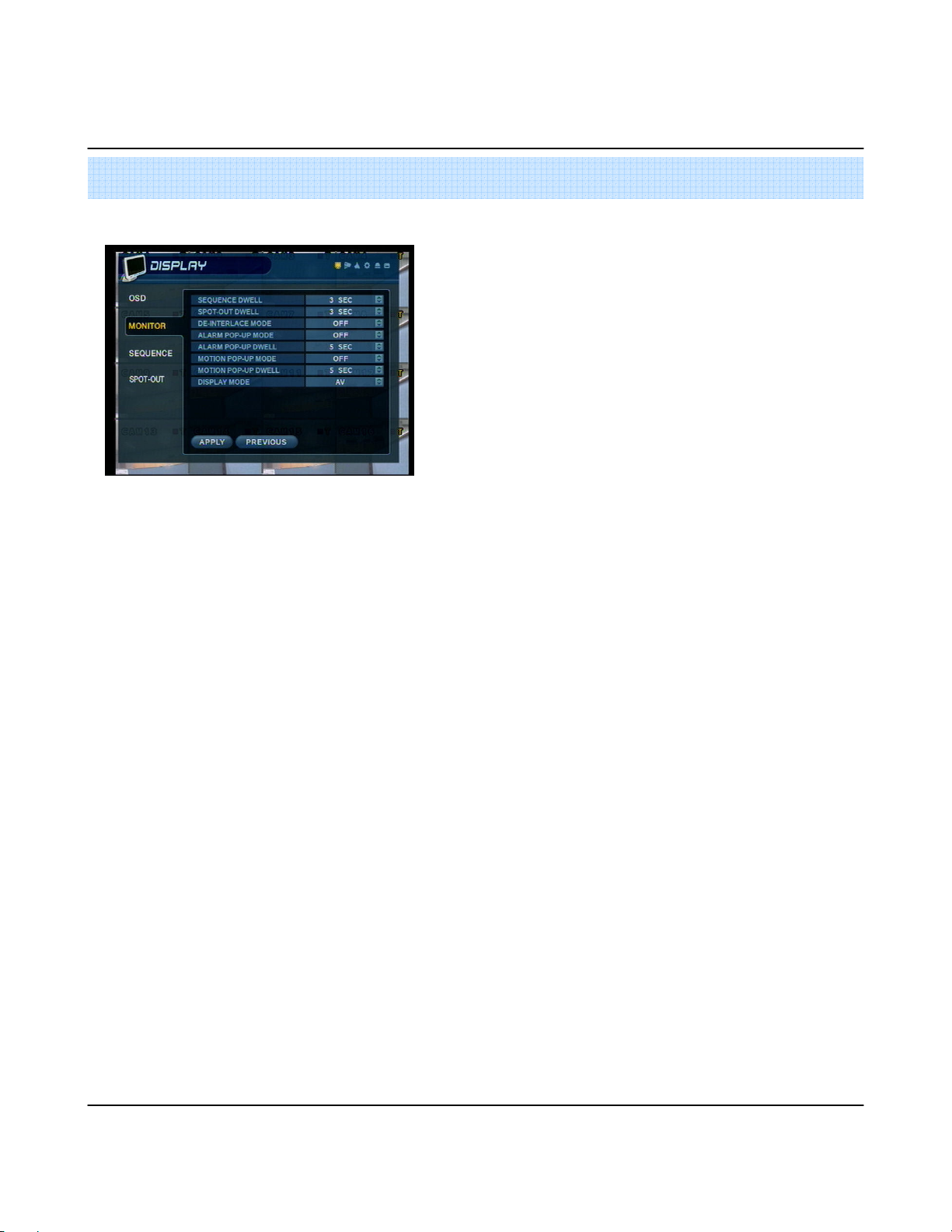
1111----2. MONITOR
2. MONITOR
2. MONITOR2. MONITOR
•Sequence dwell : Set up channel sequence cycle time (1-60 sec).
•Spot-out dwell : Setup spot-out time cycle(1~60 sec.).
•De-interlace mode : Remove interlacing in high resolution & low frame.
* This applies only D1 resolution. (704X480)
•Alarm pop-up mode: alarm channel will go full screen on activation.
•Alarm pop-up dwell: alarm pop-up time (1~60sec.)
• Motion pop-up mode : motion channel will go full screen on activation.
• Motion pop-up dwell : motion pop-up time(1~60sec.)
•Display mode : select display mode. (VGA/AV)
18
Page 21
5. Setup
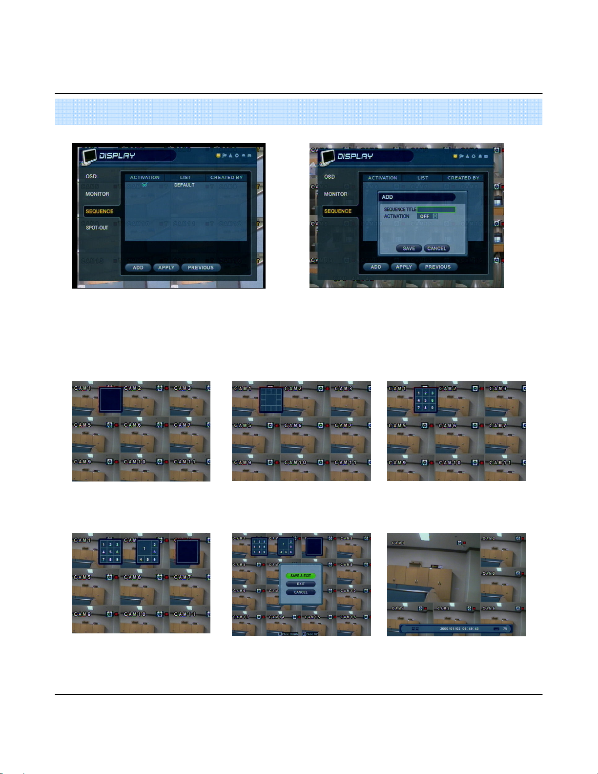
1111----3. SEQUENCE
3. SEQUENCE
3. SEQUENCE3. SEQUENCE
•Activation : Setup activation on/off.
•List : Sequence title.
•Created by user who programmed the
sequence.
**** How to setup Sequence function
How to setup Sequence function
How to setup Sequence functionHow to setup Sequence function
Press Enter, then red border line will
disappear. Setup mode will be activated.
•Choose add to add sequence.
•Input the sequence title.
•Choose activation. (on/off)
•Save and exit
Select display mode type for sequence
via navigation key.
Input channel No. for sequence function
via virtual keyboard.
User will add up new sequence type as
different type
Press return button after finishing setup,
Finally, select Save & Exit / Exit / Cancel
19
User can check sequence function by
pressing sequence button of key pad.
Page 22

5. Setup
1111----4. SPOT OUT
4. SPOT OUT
4. SPOT OUT4. SPOT OUT
•Channel : Select spot out channel (4CH=> 1 SPOT, 8CH=> 2 SPOT,
16CH=> 4 SPOT)
•Select camera channel for spot out
• User can see the selected channel via AV monitor
20
Page 23
5. Setup
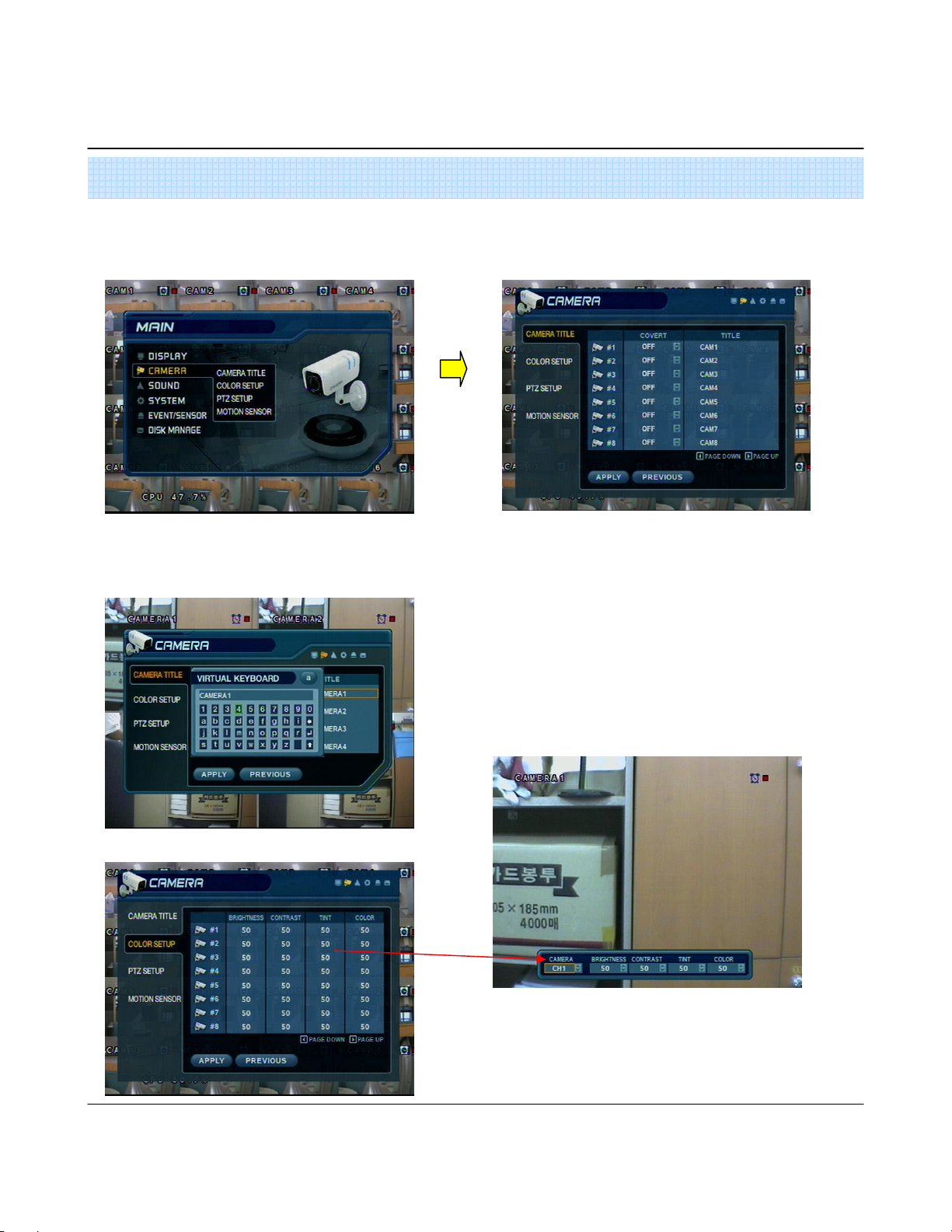
2. Camera
2. Camera
2. Camera 2. Camera
- Allow setup of camera Parameters and Options
2222----1. Camera Title
1. Camera Title
1. Camera Title1. Camera Title
•Covert : Setup channel as Covert channel (on/off)
=> What’s Covert?
When a channel is set to covert, it will be hidden Live view and Playback, but video will still be recorded.
•Title : User will input camera name by using virtual key board.
2222----2. Color Setup
2. Color Setup
2. Color Setup2. Color Setup
• Use the enter button to click the keyboard.
•Adjust the brightness, contrast, color and tint of each channel
•All values range from 0-100 (all values are 50 by default)
• User need to set these values on each channel individually.
21
Page 24
5. Setup
Tip
Tip
TipTip
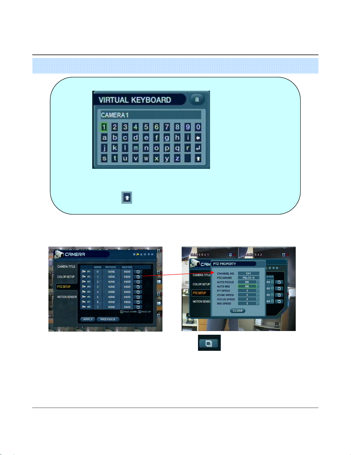
2222----3. PTZ Setup
3. PTZ Setup
3. PTZ Setup3. PTZ Setup
How to use Virtual Keyboard
•Input the directional buttons to select keys on the virtual keyboard.
•Press enter to press a key on the keyboard.
•Press the button for shift for CAPS and punctuation.
•Address : Select the PTZ Camera Address (0-255).
•PTZ Protocol : Select type of PTZ Camera. • Enter button and setup the PTZ details.
•Baud Rate : Setup PTZ Communication Speed.
(2400, 4800, 9600,19200, 38400 BPS)
PTZ Supplied Protocol : Samsung(MRX-1000), Samsung(SCC641),Honeywell(SD1)
Honeywell((GMC),Lilin(Fastdome), Fastrax(), GC(655N),
D-MAX, Sunin DSC-230, Scan Dome-, Vicon,Philips8560-700
Sensormatic,Panasonic(WV-CS850), Panasonic(WV-CSR604),VRX-2101
Kalatel(KTD-312), PELCO-D, PELCO-P,Dynacolor(D7722)
22
Page 25
5. Setup
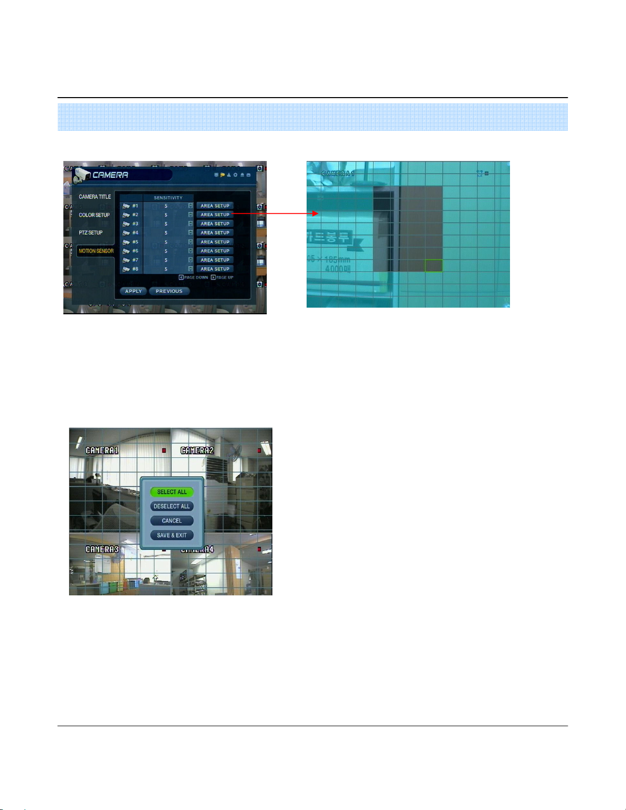
2222----4. Motion Detection
4. Motion Detection
4. Motion Detection4. Motion Detection
•Adjust the Motion Sensitivity Level (1-10)
•Click area setup to define motion-sensitive area.
•Area is selected on a 16 x 16 target grid. (The entire viewing
area is selected on all channels by default)
• Move cursor over grid using the Directional keys.
•Press Enter, and then use the Directional Keys to select an
area of targets on the grid.
•Press Enter aging to mark the selected area.
( An area that is already marked will be unmarked)
•Press Return key to step back out of Area Setup
•Select All : Select entire area for Motion sensitivity.
•Deselect All : De-Select entire area
•Cancel : Cancel changes to setup & exit.
•Save & Exit : Save the changes & Exit.
23
Page 26

5. Setup
3. Sound
3. Sound
3. Sound3. Sound
3333----1. Audio
1. Audio
1. Audio1. Audio
- Allows for configuration of audio parameters and options
3333----2. Buzzer
2. Buzzer
2. Buzzer2. Buzzer
- System Buzzer Setup
•Live Audio : Audio output to audio out terminal (ON/OFF).
(Live audio output is from audio in terminal)
•Audio Monitoring Channel: Select channel for audio output.
• Network Audio TX: Allow transmission of live audio over network
• Network Audio RX: Allow reception of audio talkback from PC.
•Keypad : Buzzer will chirp when button is pressed on Front Panel.
•Remocon : Buzzer will chirp when button is pressed on Controller.
24
Page 27

5. Setup
4. System
4. System
4. System4. System
- Basic System environment Setup
4444----1. Date/Time
1. Date/Time
1. Date/Time1. Date/Time
User should set the proper Time zone for your geographic location before adjusting the other settings.
•Date time : Set the present date & time.
•Date Format : Select the style of date display. (Ex: 2005-00-00, 2005/00/00)
•Time Format : Setup time display as either 12 Hour or 24 Hour base.
• Network time server : Setup on NTP time server, to synchronize date/Time with other devices on the network
•D.S.T: Daylight Saving Function (On/Off).
Tip
Tip
TipTip
•Time Zone Setup : Choose the time zone (Relative to GMT
standard).
How to perform Date/Time setup via network (NTP) time server ;
1. Setup Time zone for your geographic location.
2. Setup the Network Time server information and press the “ Sync” button.
3. If correct time is not retrieved automatically, set the date/time manually.
4. If the correct date/time is not set, you may experience problems when using Date/Time search.
25
Page 28

5. Setup
4444----2. Network
2. Network
2. Network2. Network
•IP Address : Input the unit IP Address.
•Gateway : Input the IP address of Internet-connected Router
•Subnet Mask : Input the Subnet Mask IP.
•DNS Server: Input 1STAND 2NDDNS Server IP Addresses.
•DDNS Server: Input DDNS server IP address
• Net Client Port : Input net client Service Port # (Default:6100)
• Web Server Port : Input the Web server port # (Default: 80)
• Max TX Speed : Setup Max Network TX Speed. (56k – 8mbbs)
** After making changes to the Network setup, click Apply.
(The system will prompt you to reboot in order to save change.)
•DHCP (Dynamic Host Configuration Protocol) : IP address is set on the DVR automatically by DHCP server/router.
1. Set DHCP setting (On/Off)
2. DHCP Off : User will input IP address manually.
3. DHCP On : IP address will be assigned automatically. After DHCP is set to On, the system will reboot.
4. After the system has restarted, you can view the new IP address from this menu or in ‘ System information’
•DDNS (Dynamic DNS): This is used with a Dynamic IP address, which may be changed by the ISP at any time.
With DDNS, there is no need to enter the IP address on every connection, A name server address is used instead of.
1. Setup DHCP to on or manually input the unit IP address.
2. Setup DDNS to On, set the DDNS properties (user name, password, and domain name) and reboot the system.
3. To access the DVR using the name server address, the format for the address is :
http:// [user name].[domain]
([Example: http:// mydvr.dyndns.org) (user name: mydvr.domain: dyndns.org)
4. User will need to input all of the correct DDNS information into the Network setup in order for the DVR to be able to
update its new IP address to the DDNS server whenever a change occurs.
5. If user is using a router in your network configuration, it is the router which must be setup for DDNS, not the DVR.
. About Network Configuration
1. If your DVR is connected to the Internet via a Router, you must use Port Forwarding in order for users outside of
your Local Area Network (LAN) to access the DVR remotely over the Internet.
2. Forward the Web and Client Service Port #’s to the Private (LAN) IP Address of the DVR.
3. The Router and DVR must have IP Addresses that are located on the same network subnet.
Tip
Tip
TipTip
4. Users connect to the DVR over the Internet using the Router’s Public (WAN) IP Address.
5. If the Port Forwarding settings are correct in the Router, it will forward all data to/from the DVR.
6. If the DVR is the only device using your Internet Connection,it will be assigned the Public (WAN) IP Address that is given
to you by your Internet Service Provider (ISP).
Example: Router IP: 192.168.0.1 DVR IP: 192.168.0.x (x is any number from 2 ~ 254)
26
Page 29

5. Setup
4444----3. Mail
3. Mail
3. Mail3. Mail
These settings allow the DVR to send outgoing E-mail notifications to the list of recipients listed within the DVR
•Server: Setup the outgoing Mail server address.
•Input the server address using the Virtual Keyboard.
•Port: Mail server port number (default is port 25).
•Security: For a mail server the requires outgoing SMTP Authorization (On/Off).
• User & password: Input the username and password (if required for outgoing SMTP Authorization).
27
Page 30

5. Setup
4444----4. User Management
4. User Management
4. User Management4. User Management
DVR User account Setup
• There are 3 groups of User Account types
- Administrator, Manager, and User.
•A Total 7 users can be established for each account type.
•Input the new User ID,
•Input a password, using channel selection buttons (0-9)
•Choose the Group which the user belongs to.
•Input the E-mail Address for the new user.
•Turn E-mail notification (on/off)
•Input User ID and E-mail address using the Virtual Keyboard.
28
Page 31

5. Setup
4444----5. System
5. System Management
5. System 5. System
Management
ManagementManagement
•F/W version: DVR Server firmware version.
• H/W version : DVR Hardware version.
•Video signal type: NTSC or PAL.
•Disk capacity: Used HDD capacity/ total HDD capacity.
•IP address: Current IP address of the DVR.
• MAC address: Fixed MAC address of the DVR.
•F/W update
- User can do F/W update by USB (or CD) device.
- Press ‘Press’
- Select F/W from the list.
- Press ‘START’
•Factory default
- User can initialize all setup but recording data is not erased.
- Press ‘Press’then warning message appear.
- Press ‘OK’, then all setup initialized.
•System data
- User can save/load settings.
- Press ‘SAVE’ to save current setup without message.
- Press ‘LOAD’to load saved setup from USB device without message.
29
Page 32
5. Setup
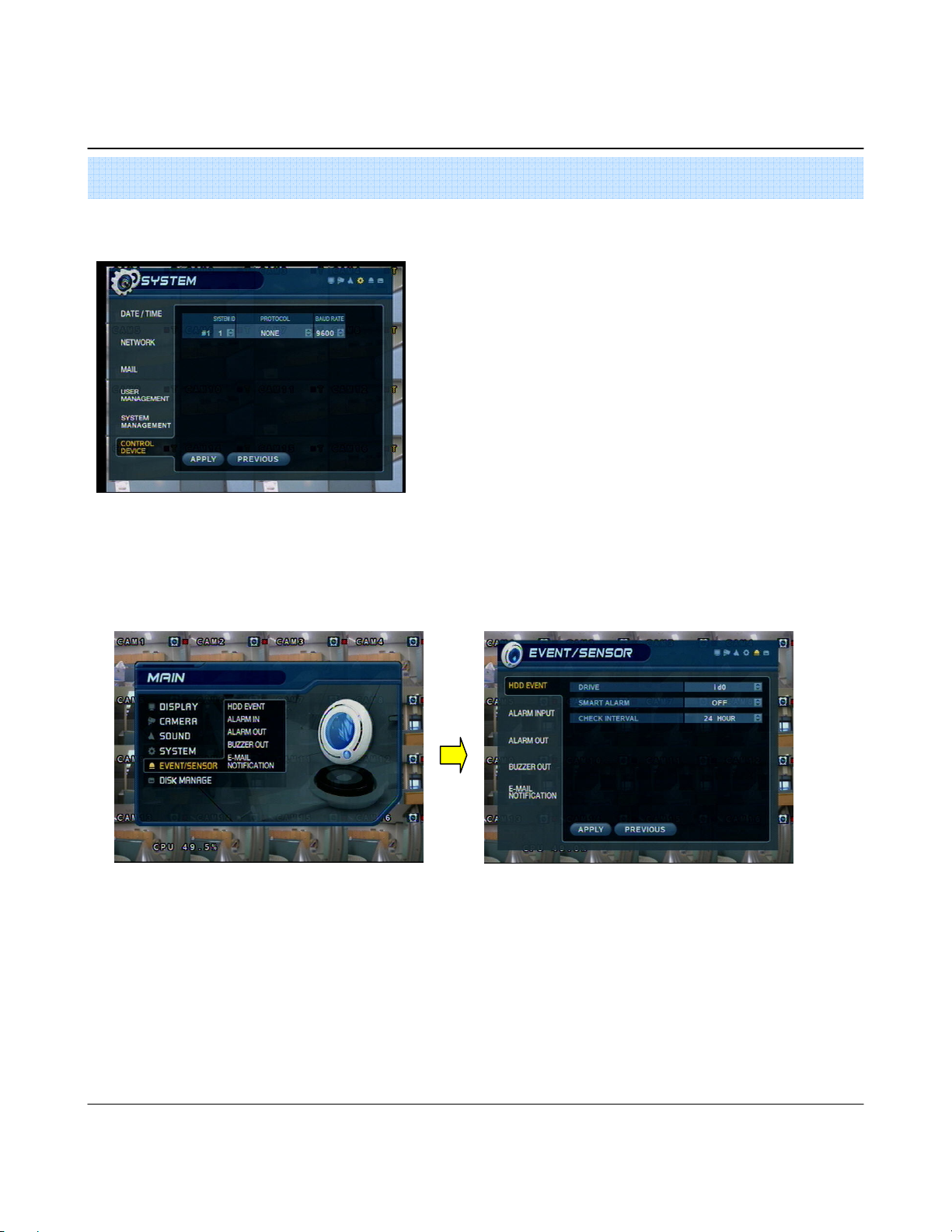
4444----6. Control device
6. Control device
6. Control device6. Control device
5. Event/Sensor
5. Event/Sensor
5. Event/Sensor5. Event/Sensor
5555----1. HDD Event
1. HDD Event
1. HDD Event1. HDD Event
•System ID : Select system ID. (1~254)
•Protocol : Select protocol.
•Baud rate : Setup baud rate.
•Drive: All HDDs are listed by IDE channel Number.
•Smart alarm: Set Temperature Alarm (on/off)
•Check interval: Time between smart alarm checks.
30
Page 33
5. Setup
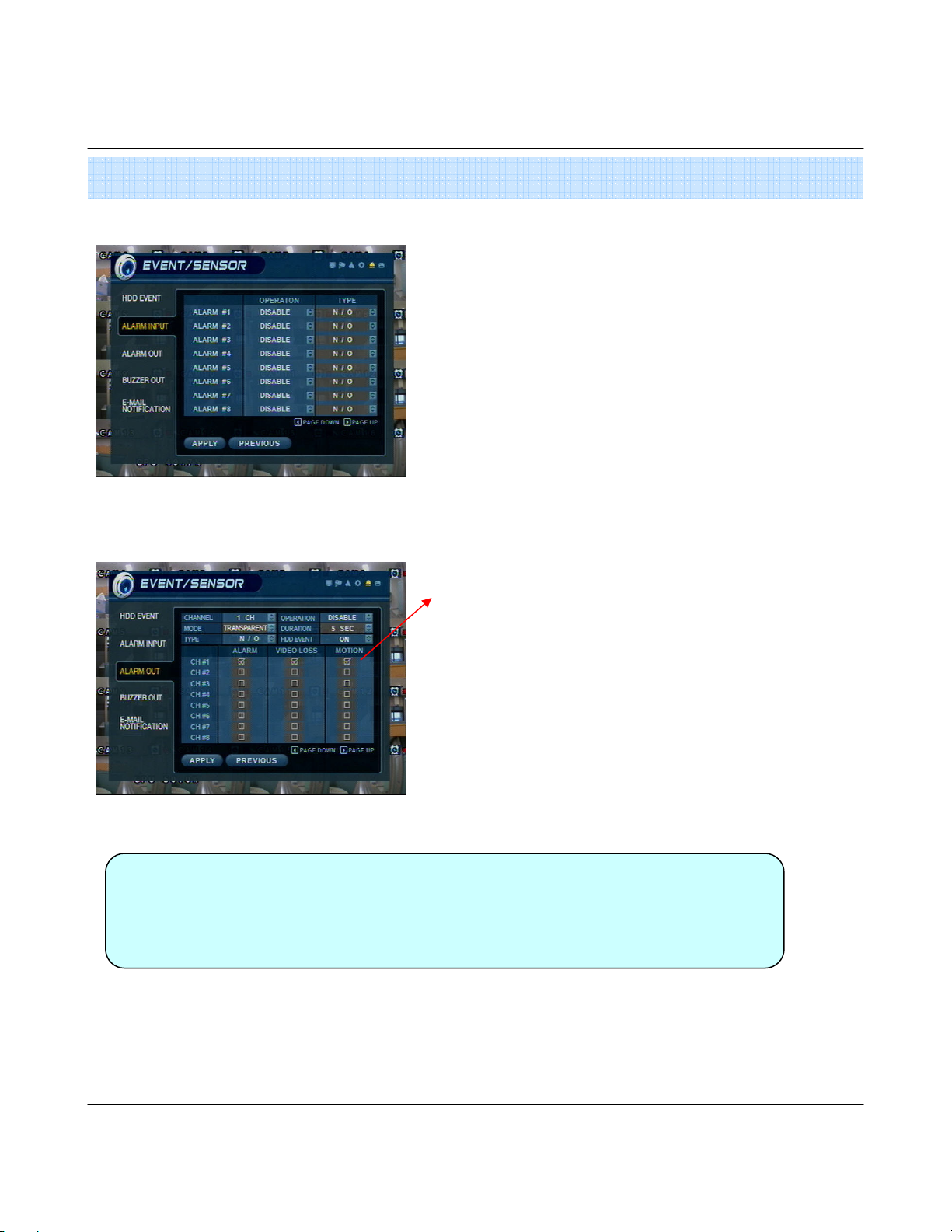
5555----2. Alarm Input
2. Alarm Input
2. Alarm Input2. Alarm Input
5555----3. Alarm Output
3. Alarm Output
3. Alarm Output3. Alarm Output
• Operation: Setup Alarm Sensor Connection Status.
(enable/disable)
•Type : Setup Alarm Sensor N/Open, N/Close Type.
• Normal Open : Open status in normal times, when alarm out
happen changed to close status .
• Normal Close : Close status in normal times, when alarm out
happen changed to open status .
•Page down/up : Move display page.
Setup each channel when alarm, video loss, motion happened.
•Channel : Select Channel.
• Mode: Setup Reacted Relay as Latched/Transparent Mode.
•Type: Setup Relay Type N/Open or N/Close.
• Operation: Setup Relay Connect with Alarm Sensor.
•Duration: Setup Reacted Relay Time. (5sec~5min or Until key-in)
• HDD Event: Alarm On/Off when HDD has the problem.
•Page down/up : Move display page.
Tip
Tip
TipTip
•Latched/Transparent
Latched – When sensor alarm activated, relay reacted in setup duration.
Transparent – Relay reacted temporary during sensor alarm activate.
31
Page 34

5. Setup
5555----4. Buzzer out
4. Buzzer out
4. Buzzer out4. Buzzer out
• Operation: Buzzer Out (Enable/Disable).
• Mode: Setup in Latched/Transparent Mode (same as Alarm out).
• HDD Event: Turn buzzer (on/off) when HDD event occurs.
•Duration: Buzzer time (5sec~5min or manual reset on DVR)
•Setup each channel to trigger buzzer on alarm activation, video
loss, and/or motion event.
32
Page 35
5. Setup
5555----5. E
5. E----mail Notification
mail Notification
5. E5. E
mail Notificationmail Notification
6. Disk Management
6. Disk Management
6. Disk Management6. Disk Management
•E-Mail Notification will send an e-mail to a list of recipients, based on alarm,
video loss, motion, or HDD events.
•Check or uncheck each type of condition that you want to trigger an E-mail
notification, on each channel.
•The list of recipients is configured within the System User Management menu.
• Make sure that all of the outgoing mail server settings are correct, within the
system Mail menu, in order to ensure delivery.
•Disk Overwrite : (ON/OFF) overwrite permission (when HDD is full)
ON: Overwrite HDD, starting with the oldest data first (also known as FIFO – first in, first out)
OFF: When HDD is full, recording will be halted and the system buzzer will activate
•Format : (Click START to Format HDD). All Recorded data will be deleted from the HDD.
[NOTE: Any newly-installed HDDs will be detected during the Power-On Self Test (POST), and the system will prompt you to Format the
new HDD before entering into the DVR system GUI. You can’t format new HDDs from the disk management menu, until they have been
formatted first during the startup sequence.]
33
Page 36
5. Setup
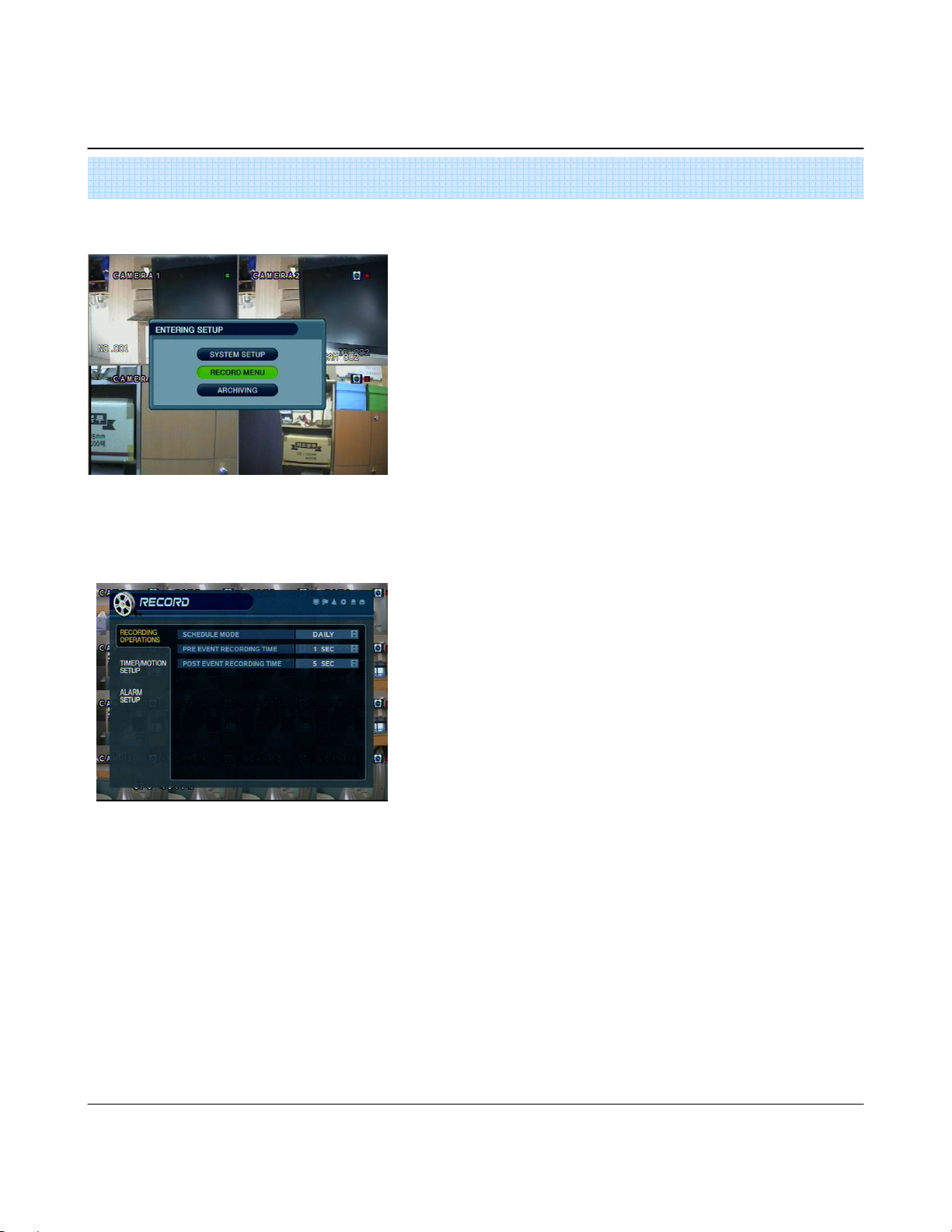
Go to Record Menu
Go to Record Menu
Go to Record MenuGo to Record Menu
1. Recording Operations
1. Recording Operations
1. Recording Operations1. Recording Operations
•Press the setup button and login as an Administrator.
•Choose “ Record Menu”
•Schedule Mode: Choose ‘DAILY’ or ‘WEEKLY’.
- Daily : The recording schedule that you configure will be used for every day of
the week.
- Weekly: You must configure the recording schedule for each day of the week,
individually.
•Pre-Event recording time : (1 ~ 5 seconds) data will be recorded to the HDD from
1 to 5 seconds before an event is detected.
•Post-Event Recording Time : (5 sec ~ 3 min) Data will be recorded to the HDD
from 5 seconds to 3 minutes after an event has ended.
34
Page 37
5. Setup
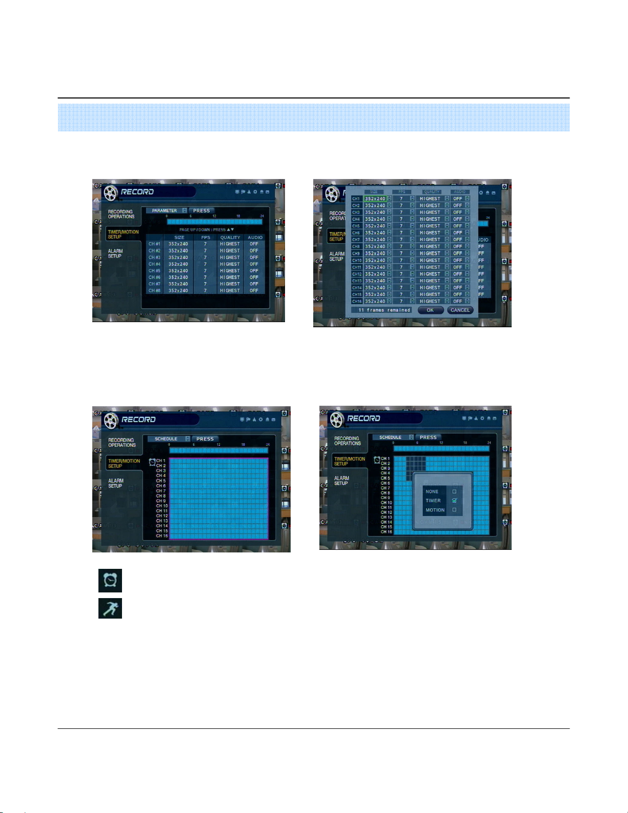
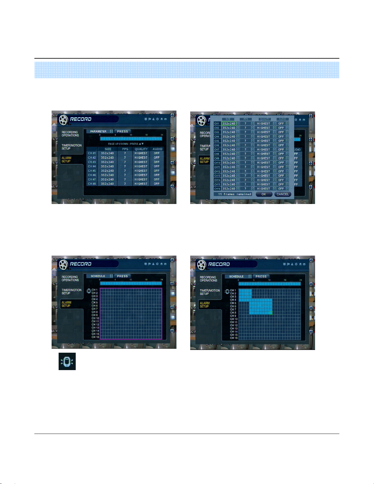
2. Continuous / Motion Record Schedule
2. Continuous / Motion Record Schedule
2. Continuous / Motion Record Schedule2. Continuous / Motion Record Schedule
2222----1. Parameter
1. Parameter
1. Parameter1. Parameter
•Select a block of time from the 0-24hr Timeline (you may select multiple blocks).
•Press ENTER again to set up the Resolution, FPS, Quality, and Audio on each channel.
2222----2. Schedule
2. Schedule
2. Schedule2. Schedule
• Continuous recording Icon
• Motion recording Icon
•If ‘WEEKLY’ recording is enabled, you must set up each day of the week individually.
•If ‘DAILY’recording is enabled, you will set up one schedule for every day of the week.
• Select an area (channel / time of day) on the schedule grid and
press enter to adjust its properties.
• Set area as ‘Timer’(Continuous), ‘Motion’, or None.
35
Page 38
5. Setup
3. Alarm Recording Schedule
3. Alarm Recording Schedule
3. Alarm Recording Schedule3. Alarm Recording Schedule
3333----1. Parameter
1. Parameter
1. Parameter1. Parameter
•Select a block of time from the 0-24hr timeline (you may select multiple blocks).
•Press ENTER again to set up the resolution, FPS, quality, and audio on each channel.
3333----2. Schedule
2. Schedule
2. Schedule2. Schedule
• Alarm recording icon
•If ‘WEEKLY’ recording is enabled, you must set up each day of the week individually.
•If ‘DAILY’recording is enabled, you will set up one schedule for every day of the week.
• Select an area (channel / time of day) on the schedule.
• Press enter to select (or deselect) alarm recording.
36
Page 39
5. Setup
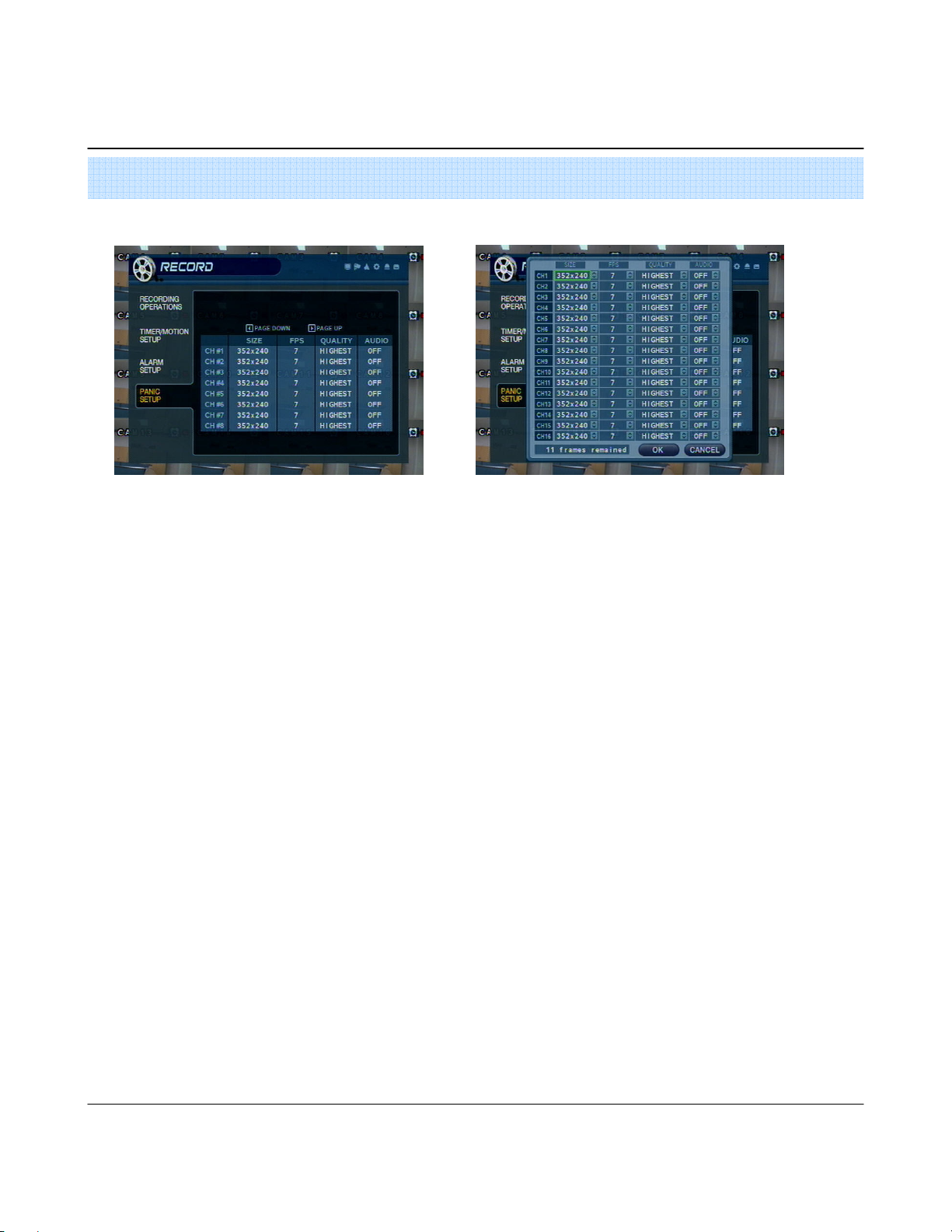
4. Panic Setup
4. Panic Setup
4. Panic Setup4. Panic Setup
•To setup each channel, press enter.
•Setup each channel. (Size, FPS, Quality, Audio)
•By using panic button of front panel can record urgently as setup.
37
Page 40
5. Setup
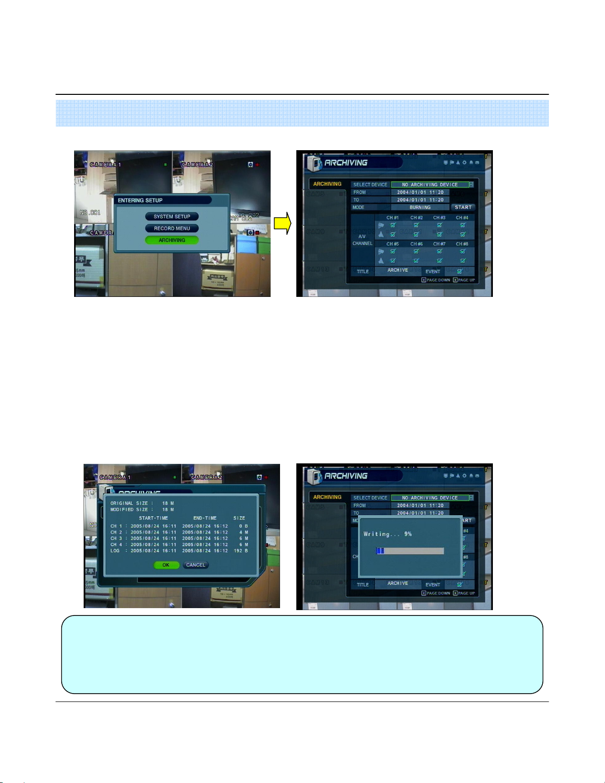
Go to Archiving
Go to Archiving
Go to ArchivingGo to Archiving
1. CD
1. CD----RW and USB Back Up
1. CD1. CD
RW and USB Back Up
RW and USB Back UpRW and USB Back Up
•Device : Indicate CD-RW model and USB memory model automatically.
If you use the CD-RW and USB memory (or USB HDD) together,
it can choose the CD-RW and USB by direction key.
•From : Select start backup time.
•To : Select end backup time.
• Mode : Select backup mode. (Burning / Erasing & Burning)
•A/V channel: Select channel, video, audio for backup.
•Title : Change the title of backup by virtual keyboard.
•Event : Select attach event text file in backup.
•Start : Start backup.
Tip
Tip
TipTip
•Compatible CD Writer Models are LG(GCE-8526B,GCE-8527B),
SAMSUNG(SW-252F, TS-H292A, SH-522C),ASUS(CRW-5232AS),GIGABYTE(GO-R5232B)
• Compatible USB memory stick Models are LG(Royal,mobile,mirror), IMATION(iflash),Memorive PRO+
and Compatible USB HDD is CUTIE(FHD-254).
•Inside of Backup CD,USB Including Necessary Codec for Playback (IMM4 Install File).
•In case of RW Possible CD, Please Delete Previous Data on PC for Recording Again.
38
Page 41
* HDD Installation
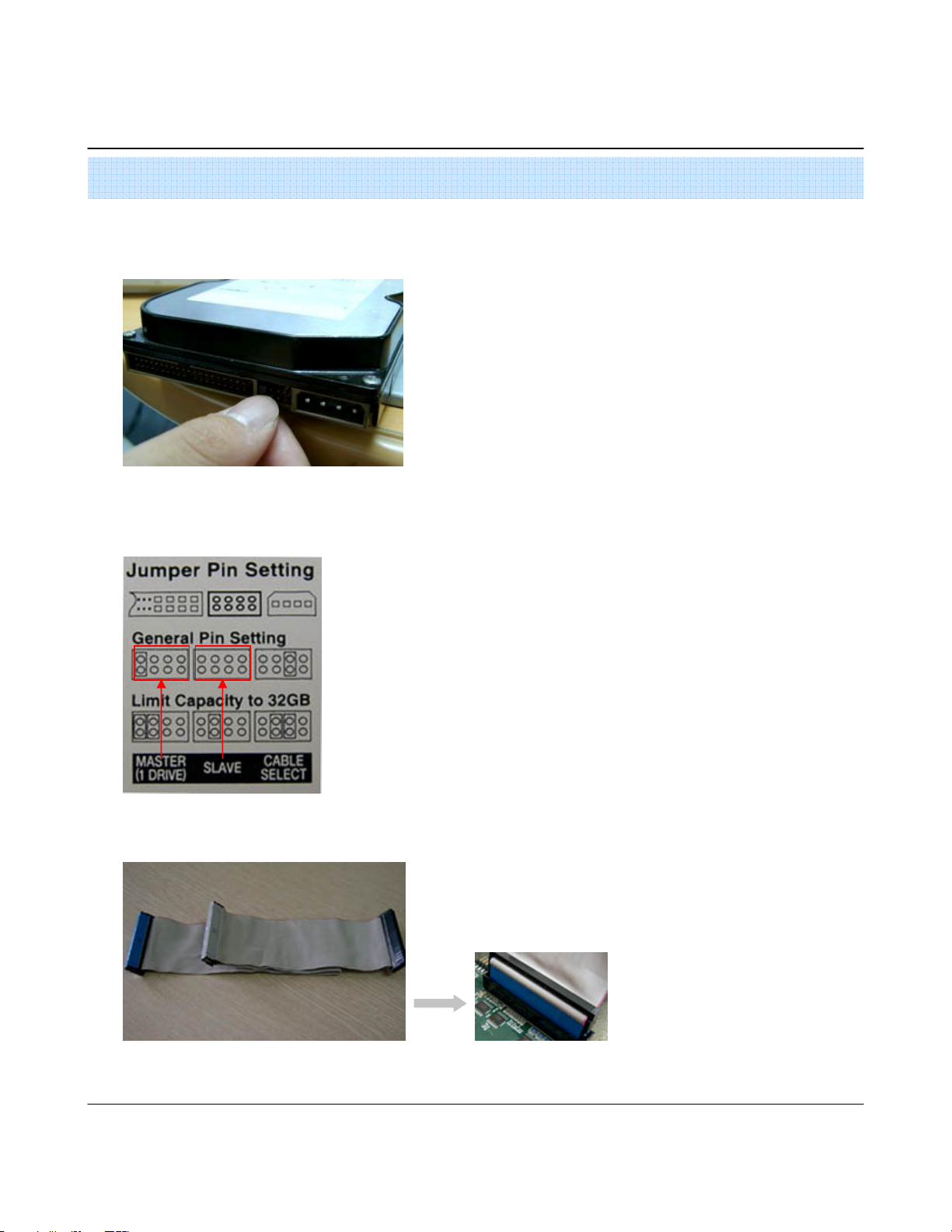
Jumper Setup as Master or Slave
Jumper Setup as Master or Slave
Jumper Setup as Master or SlaveJumper Setup as Master or Slave
Example of Samsung HDD Jumper Setup
Example of Samsung HDD Jumper Setup
Example of Samsung HDD Jumper SetupExample of Samsung HDD Jumper Setup
SUPPLEMENT
SUPPLEMENT
SUPPLEMENTSUPPLEMENT
•Jumper Setup as master or Slave, Following the `
Direction of Surface of Hard Disk.
•Jumper Located at Hard Disk Data Cable or 1
Rear Side of Hard Disk.
•If one hard disk Installation, setup as Master If
two hard disk Installation, second one setup as slave.
‼ When hard disk add or exchange, Must system off properly
(System off by power button). If not, it’s a cause of fatal hard
disk error.‼
•Refer to general pin setting in jumper pin setting on HDD surface.
• When one HDD install, setup pin as master and connect pin 1 at
the left end of jumper.
• When two HDD Install or additional Install, first one setup as 1 master
and the other is for slave. slave setup has no pin.
• When more than two HDD install, setup as master or slave
1 to connect one IDE cable at the same method of above.
IDE Cable Connection to Main Board
IDE Cable Connection to Main Board
IDE Cable Connection to Main BoardIDE Cable Connection to Main Board
!!Please use hard disk which possible to supply higher than UDMA66.!!
• Confirm the IDE cable inside of product
• Among the three connector, Indicated blue
color 1 connector must be connected
with main board. other 1 connectors
connected with HDD
39
Page 42

•••• IMPORTANT SAFETY INSTRUCTIONS
1) Read these instructions.
2) Keep these instructions.
3) Heed all warnings.
4) Follow all instructions.
5) Do not use this apparatus near water.
6) Clean only with a dry cloth.
7) Do not block any of the ventilation openings. Install in accordance with the manufacturer's
instructions.
8) Do not install near any heat sources such as radiators, heat registers, stoves, or other apparatus
that produce heat.
9) Do not defeat the safety purpose of the polarized or grounding type plug. A polarized plug has
two blades with one wider than the other.
A grounding type plug has two blades and a third grounding prong.
The wide blade or the third prong is provided for your safety.
When the provided plug does not fit into your outlet, consult an electrician for replacement
of the obsolete outlet.
10) Protect the power cord from being walked on or pinched particularly at plugs, convenience
receptacles, and the point where they exit from the apparatus.
11) Only use the attachments/accessories specified by the manufacturer.
12) Use only with a cart, stand, tripod, bracket, or table specified by the manufacturer, or sold
with the apparatus.
When a cart is used, use caution when moving the cart/apparatus combination to avoid injury
from tip-over.
13) Unplug this apparatus during lightning storms or when unused for long periods of time.
14) Refer all servicing to qualified service personnel. Servicing is required when the apparatus
has been damaged in any way, such as power supply cord or plug is damaged, liquid has
been spilled or objects have fallen into the apparatus, the apparatus has been exposed to
rain or moisture, does not operate normally, or has been dropped.
15) This equipment is indoor use and all the communication wirings are limited to inside of the
building.
40
Page 43

Page 44

GERMANY
C
R
Installations- und Betriebsanleitung
R
VC Videocomponents GmbH
GERMANY
C
Änderungen in T echnik, Design und Ausst attung vorbehalten
Brachenfelder Str . 45
D-24534 Neumünster
Tel.: ++ 49 (0) 4321 - 39 05 40
Fax: ++ 49 (0) 4321 - 28 04 82
e-mail: mail@vcvideo.de
Internet: www.vcvideo.de
All contents of this document may change without prior notice
Service
Tel.: ++ 49 (0) 4321 - 3 90 54 33
e-mail: technik@vcvideo.de
All rights are reserved.
IB_12760-OHR
 Loading...