

Page 1
®
Vision
Components
®
The Smart Camera People
VC72XX Operating Manual
Hardware Specifications and special Software Functions of
VC72XX Smart Cameras
Revision 1.5 – 27 Jan 2016
Document name: VC72XX_HW.pdf
Vision Components GmbH Ettlingen, Germany
Page 2

VC72XX_HW.pdf – Hardware Documentation VC72XX Smart Cameras
1996-2016 Vision Components GmbH Ettlingen, Germany
2
Foreword and Disclaimer
This documentation has been prepared with most possible care. However Vision Components GmbH
does not take any liability for possible errors. In the interest of progress, Vision Components GmbH
reserves the right to perform technical changes without further notice.
Please notify support@vision-components.com if you become aware of any errors in this manual or
if a certain topic requires more detailed documentation.
This manual is intended for information of Vision Component’s customers only. Any publication of this
document or parts thereof requires written permission by Vision Components GmbH.
Trademarks
Code Composer Studio and TMS320C6000, Windows XP, Total Commander, Tera Term, Motorola
are registered Trademarks. All trademarks are the property of their respective owners.
Further References under “Support + Download ” on www.vision-components.com:
„Support News“ – for up to date information on VC Software and Documentation.
„Knowledge Base / FAQ“ - searchable Database with latest software developments, frequently asked
questions and demo programs.
“Download Areas” for all documentation and Software downloads – refer to the following table:
Description Title on Website Download Center
Introduction to VC Smart Camera
programming
Programming Tutorial for
VC20XX and VC40XX Cameras
Service & Support
Download Center
Documentation Getting Started VC
Demo programs and sample code
used in the Programming Tutorial
Tutorial_Code
Service & Support Download Center
Documentation Getting Started VC
VC4XXX Hardware Manual
VC4XXX Smart Cameras
Hardware Documentation
Service & Support
Download Center
Documentation Hardware
VCRT Operation System Functions
Manual
VCRT 5.0 Software Manual
Service & Support
Download Center
Documentation Software
VCRT Operation System TCP/IP
Functions Manual
VCRT 5.0 TCP/IP Manual
Service & Support
Download Center
Documentation Software
VCLIB 3.0 Image Processing Library
Manual
VCLIB 3.0 Software Manual
Service & Support
Download Center
Documentation Software
The Light bulb highlights hints and ideas that may be helpful for a development.
This warning sign alerts of possible pitfalls to avoid. Please pay careful attention to sections
marked with this sign.
Author: VC Support, mailto:support@vision-comp.com
!
Page 3

VC72XX_HW.pdf – Hardware Documentation VC72XX Smart Cameras
1996-2016 Vision Components GmbH Ettlingen, Germany
3
Table of Contents
1
General Information 4
2 Technical Specifications VC72XX 5
2.1 Technical Specificat ions V C721 0 5
2.2 Technical Specifications VC7211 7
2.3 Technical Specifications VC7215 9
2.4 Technical Specifications VC7222 11
2.5 Technical Specifications VC7224 12
3 VC72XX Camera Interfaces 14
3.1 LAN / Ethernet Interface 15
3.1.1 Pin Assignments LAN / Ethernet Interface 15
3.1.2 Available Accessories for LAN / Ethernet socket 15
3.2 Trigger & Serial (RS232) Interface 16
3.2.1 Pin Assignments Trigger & Serial (RS232) Interface 16
3.2.2 Trigger Cable 16
3.2.3 Serial (RS232) Cable 17
3.2.4 Y-Cable 17
3.2.5 Electrical Specifications of Trigger & Serial (RS232) Interface 18
3.3 Power Supply and IO Interface 22
3.3.1 Pin assignments Power Supply and IO Interface 22
3.3.2 Electrical specifications Camera Power Supply Camera 22
3.3.3 Electrical Specifications digital PLC IO Interface 23
3.3.4 Available Accessories / Cables for Power Supply and IO Interface 24
4 Order Numbers Cameras and Accesso ries 25
4.1 Order numbers of all available VC72XX Camera Models: 25
4.2 Order numbers of all available VC72XX Accessories 25
5 Programming VC72XX Smart Cameras 29
5.1 General settings 29
5.2 Compiling and linking with the VC72XX cameras 29
5.3 Image Acquisition 29
Appendix A: Block diagram VC72XX Smart Cameras A
Appendix B: Dimensions VC72XX B
Appendix C: Drawing Camera Head VC72XX C
Appendix D: Spectral Transmission of IR Filter D
Page 4
VC72XX_HW.pdf – Hardware Documentation VC72XX Smart Cameras
1996-2016 Vision Components GmbH Ettlingen, Germany
4
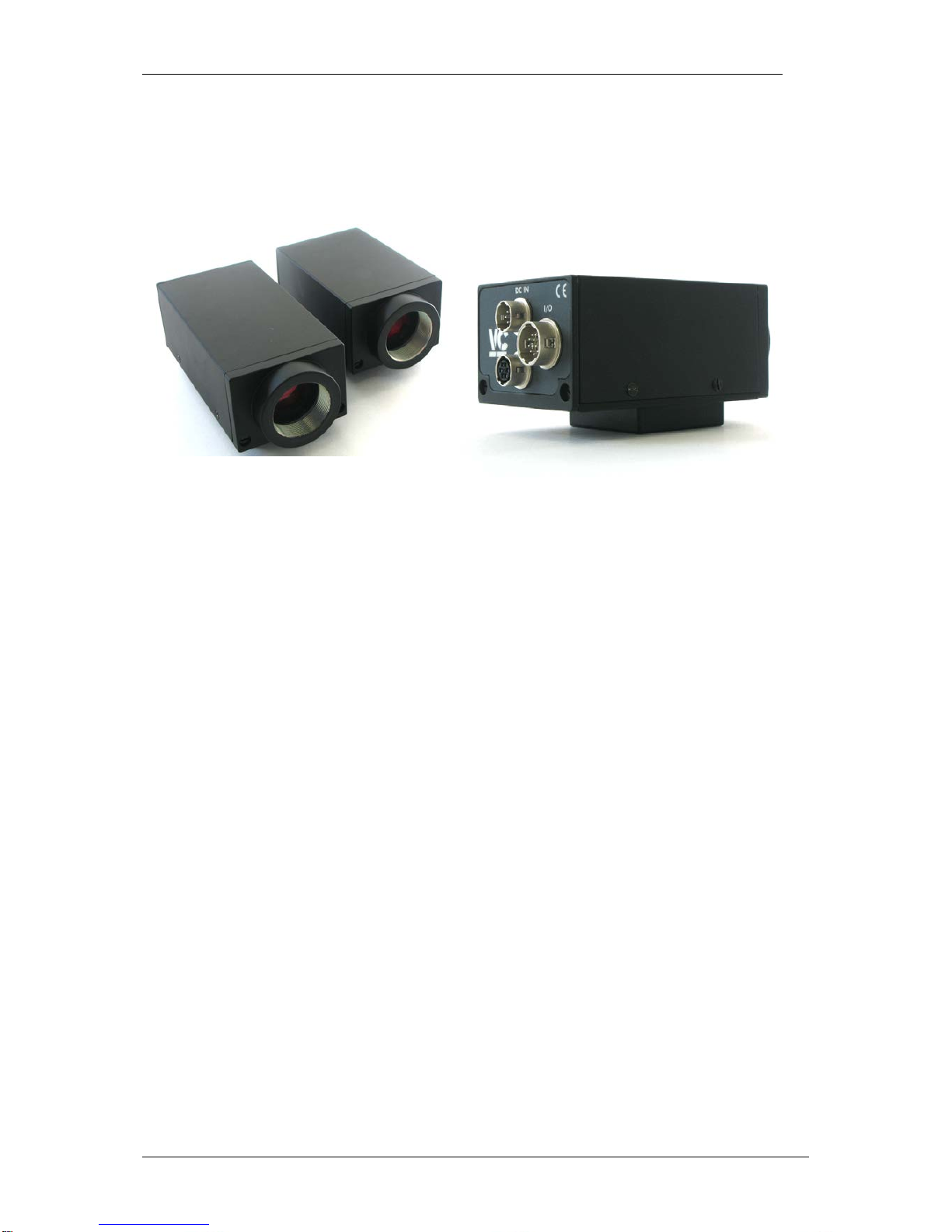
1 General Information
VC72XX housing
VC72XX Smart Camera series rear view
The VC72XX Smart Camera series from Vision Components incorporates the VC nano platform in
the well-known Vision Components housing.
Employing CMOS sensors, the image resolution can be changed to the ROI required.
Like with all VC Smart Cameras with Texas Instruments DSP, the operating system VCRT allows
multi-tasking. This means for instance that user interface commands can execute in parallel without
stopping the inspection process. It is also possible to transfer live images via TCP/IP using a
background task.
Interfaces include a video output onto a PC via 100MBit Ethernet interface, a high speed trigger input
and output, 12-24 V digital inputs and outputs .
In comparison to the VC nano series, the VC72XX Smart Cameras add a serial RS232 interface.
Page 5

VC72XX_HW.pdf – Hardware Documentation VC72XX Smart Cameras
1996-2016 Vision Components GmbH Ettlingen, Germany
5
2 Technical Specifications VC72XX
2.1 Technical Specifications VC7210
Component / Feature Specification
CMOS Sensor: 1/3" Aptina MT9V034 - also available with color sensor (Bayer Filter)
Active pixels: 752(H) x 480(V) (Wide VGA)
Pixel size: 6.0(H) x 6.0(V) µm
Active sensor size: 4.51(H) x 2.88(V) mm
High-speed shutter: 34 μs + steps of 34 µs
Low-speed shutter: up to 1.11 sec. adjustable integration time
Integration: Global shutter
Picture taking: program-controlled or external high speed trigger, full-frame (55 frames
per second) & partial scanning, jitterfree acquisition
Parallel image acquisition Not available
Clamping: Internal to sensor
A/D conversion: 25 MHz / 10 bit, only the 8 most significant bits used for grey values
Input LUT none
Image Display Via 100 Mbit Ethernet onto PC
Processor: Texas Instruments TMS320DM6435 “Da Vinci” DSP 700 MHz,
5600MIPS
RAM: 128 Mbytes SDRAM (synchronous dynamic RAM)
Memory capacity: Up to 300 full-size grey value images in format 752 x 480
Flash EPROM: 32 Mbytes flash EPROM (nonvolatile memory) for programs and data,
in-system programmable
SD card: n.a.
Process interface: 4 inputs / 4 outputs, outputs 4x400 mA
Trigger: Fast 3.3 V TTL input and output, jitter free image acquisition
Serial Interface: 115,200 bd serial RS232 communication port
Ethernet interface: 10/100 Mbit
CE certification: CE Certification from Vision Components
Storage Conditions Temperature: -20 to 60 deg C, Max. humidity: 90%, non condensing.
Operating Conditions Temperature: 0… +55 deg C, Max. humidity: 80%, non condensing.
Power Supply 24V +/-20% DC, max. 300 mA
Power Consumption ≈2.0W
Lens Mount C Mount with IR-filter
Page 6
VC72XX_HW.pdf – Hardware Documentation VC72XX Smart Cameras
1996-2016 Vision Components GmbH Ettlingen, Germany
6
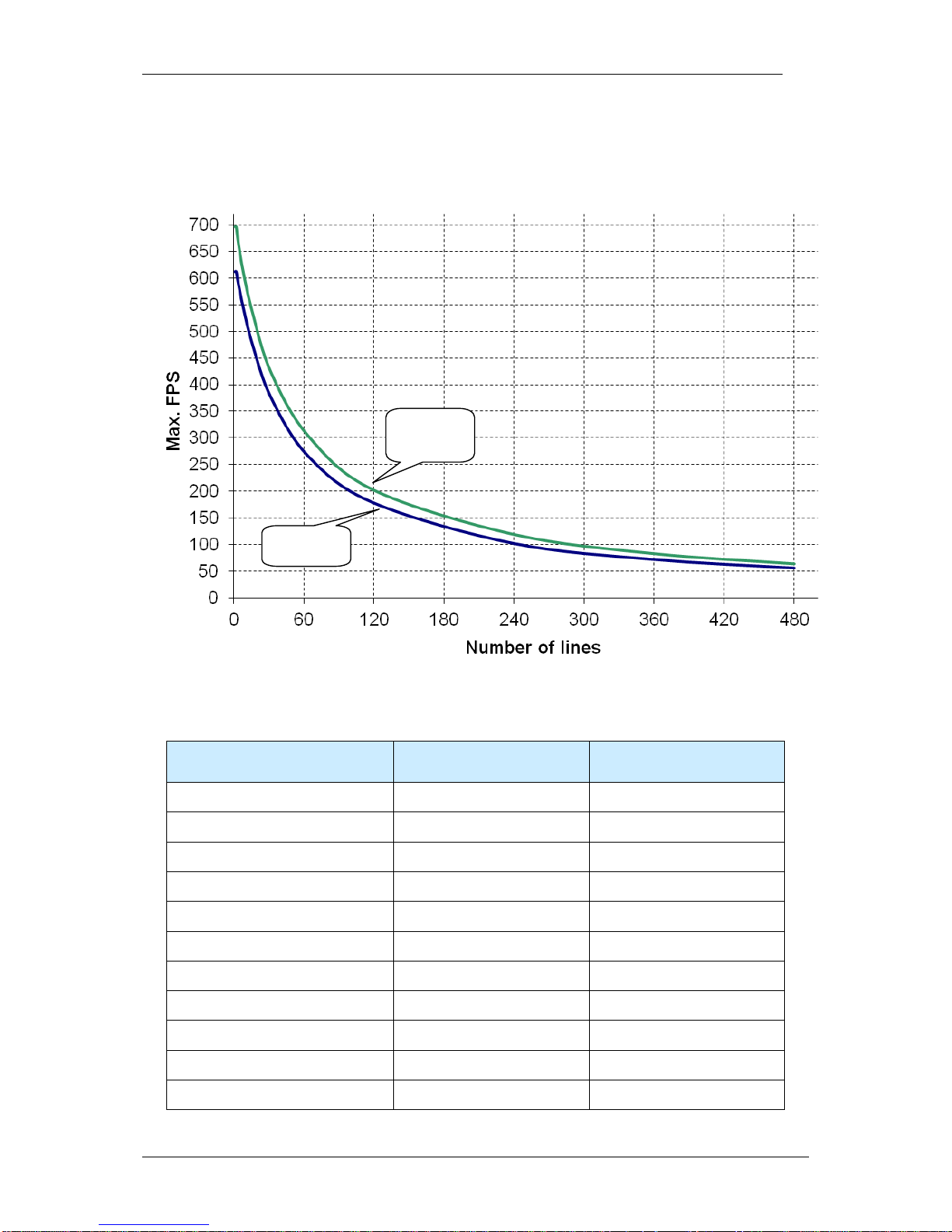
The following diagram shows the maximum reachable (with the shortest shutter time) framerate
according to the number of captured lines for the VC7210, in 2 cases:
- with an image width of 752 pixels
- with an image width of 640 pixels or less
The following table gives some example values.
Number of lines
Max. framerate (FPS)
dx = 752
Max. framerate (FPS)
dx = 640 or less
480
56
64
360
72
83
240
102
119
120
178
202
64
265
303
32
375
422
16
475
535
8
545
612
4
588
664
2
612
696
1
612
696
dx = 640
or less
dx = 752
Page 7

VC72XX_HW.pdf – Hardware Documentation VC72XX Smart Cameras
1996-2016 Vision Components GmbH Ettlingen, Germany
7
2.2 Technical Specifications VC7211
Component / Feature Specification
CMOS Sensor: 1/1.8" e2V EV76C560 - also available with color sensor (Bayer Filter)
Active pixels: 1280(H) x 1024(V)
Pixel size: 5.3(H) x 5.3(V) µm
Active sensor size: 6.8(H) x 5.5(V) mm
High-speed shutter: 21 μs + steps of 21 µs
Low-speed shutter: up to 1.35 sec. adjustable integration time
Integration: Global shutter
Picture taking: program-controlled or external high speed trigger, full-frame (50 frames
per second) & partial scanning (up to 4500 fps for 1280x1), jitterfree
acquisition
Parallel image acquisition Not available
Clamping: Internal to sensor
A/D conversion: 100 MHz / 10 bit, only the 8 most significant bits used for grey values
Input LUT none
Image Display Via 100 Mbit Ethernet onto PC
Processor: Texas Instruments TMS320DM6435 “Da Vinci” DSP 700 MHz,
5600MIPS
RAM: 128 Mbytes SDRAM (synchronous dynamic RAM)
Memory capacity: Up to 90 full-size grey value images in format 1280 x 1024
Flash EPROM: 32 Mbytes flash EPROM (nonvolatile memory) for programs and data,
in-system programmable
SD card: n.a.
Process interface: 4 inputs / 4 outputs, outputs 4x400 mA
Trigger: Fast 3.3 V TTL input and output, jitter free image acquisition
Serial Interface: 115,200 bd serial RS232 communication port
Ethernet interface: 10/100 Mbit
CE certification: CE Certification from Vision Components
Storage Conditions Temperature: -20 to 60 deg C, Max. humidity: 90%, non condensing.
Operating Conditions Temperature: 0… +55 deg C, Max. humidity: 80%, non condensing.
Power Supply 24V +/-20% DC, max. 300 mA
Power Consumption ≈2.0W
Lens Mount C Mount with IR-filter
Page 8
VC72XX_HW.pdf – Hardware Documentation VC72XX Smart Cameras
1996-2016 Vision Components GmbH Ettlingen, Germany
8
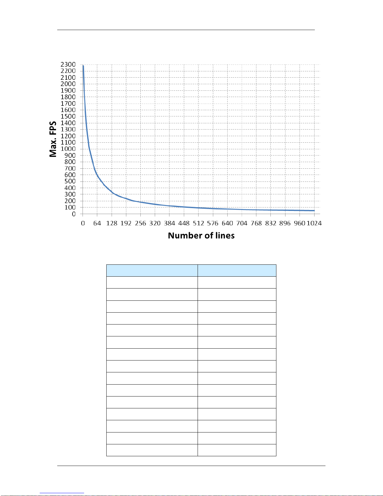
The following diagram shows the maximum reachable (with the shortest shutter time) framerate
according to the number of captured lines for the VC7211:
The following table gives some example values.
Resolution Max. framerate (FPS)
1280 x 1024
50
1280 x 768
63
1280 x 640
76
1280 x 512
94
1280 x 384
124
1280 x 256
181
1280 x 192
236
1280 x 128
339
1280 x 64
598
1280 x 32
965
1280 x 16
1392
1280 x 8
1795
1280 x 4
2092
1280 x 2
2280
1280 x 1
4500
Page 9

VC72XX_HW.pdf – Hardware Documentation VC72XX Smart Cameras
1996-2016 Vision Components GmbH Ettlingen, Germany
9
2.3 Technical Specifications VC7215
Component / Feature Specification
CMOS Sensor: 1/1.8" e2V EV76C570 - also available with color sensor (Bayer Filter)
Active pixels: 1600(H) x 1200(V)
Pixel size: 4.5(H) x 4.5(V) µm
Active sensor size: 7.2(H) x 5.4(V) mm
High-speed shutter: 1 μs
Low-speed shutter: up to 1.28 sec. adjustable integration time
Integration: Global shutter
Picture taking: program-controlled or external high speed trigger, full-frame (42 frames
per second) & partial scanning, jitterfree acquisition
Parallel ima ge acquisition Not available
Clamping: Internal to sensor
A/D conversion: 100 MHz / 10 bit, only the 8 most significant bits used for grey values
Input LUT none
Image Display Via 100 Mbit Ethernet onto PC
Processor: Texas Instruments TMS320DM6435 “Da Vinci” DSP 700 MHz,
5600MIPS
RAM: 128 Mbytes SDRAM (synchronous dynamic RAM)
Memory capacity: Up to 60 full-size grey value images in format 1600 x 1200
Flash EPROM: 32 Mbytes flash EPROM (nonvolatile memory) for programs and data,
in-system programmable
SD card: n.a.
Process interface: 4 inputs / 4 outputs, outputs 4x400 mA
Trigger: Fast 3.3 V TTL input and output, jitter free image acquisition
Serial Interface: 115,200 bd serial RS232 communication port
Ethernet interface: 10/100 Mbit
CE certification: CE Certification from Vision Components
Storage Conditions Temperature: -20 to 60 deg C, Max. humidity: 90%, non condensing.
Operating Conditions Temperature: 0… +55 deg C, Max. humidity: 80%, non condensing.
Power Supply 24V +/-20% DC, max. 300 mA
Power Consumption ≈2.0W
Lens Mount C Mount with IR-filter
Page 10

VC72XX_HW.pdf – Hardware Documentation VC72XX Smart Cameras
1996-2016 Vision Components GmbH Ettlingen, Germany
10
The following table gives some example values of maximum reachable framerates for the VC7215.
Resolution Max. framerate (FPS)
1600 x 1200
42
1600 x 1024
49
1600 x 768
64
1600 x 640
77
1600 x 512
96
1600 x 384
127
1600 x 256
185
1600 x 192
240
1600 x 128
345
1600 x 64
609
1600 x 32
984
1600 x 16
1420
1600 x 8
1795
Page 11

VC72XX_HW.pdf – Hardware Documentation VC72XX Smart Cameras
1996-2016 Vision Components GmbH Ettlingen, Germany
11
2.4 Technical Specifications VC7222
Component / Feature Specification
CMOS Sensor: 2/3" CMOSIS CMV2000 - also available with color sensor (Bayer Filter)
Active pixels: 2048(H) x 1088(V)
Pixel size: 5.5(H) x 5.5(V) µm
Active sensor size: 11.3(H) x 6.0(V) mm
High-speed shutter: 16.3 µs + steps of 5.1 µs
Low-speed shutter: Integration: Global shutter
Picture taking: program-controlled or external high speed trigger, full-frame (46 frames
per second) & partial scanning, jitterfree acquisition
Parallel image acquisition Not available
Clamping: Internal to sensor
A/D conversion: 100 MHz / 10 bit, only the 8 most significant bits used for grey values
Input LUT none
Image Display Via 100 Mbit Ethernet onto PC
Processor: Texas Instruments TMS320DM6435 “Da Vinci” DSP 700 MHz,
5600MIPS
RAM: 128 Mbytes SDRAM (synchronous dynamic RAM)
Memory capacity: Up to 50 full-size grey value images in format 2048 x 1088
Flash EPROM: 32 Mbytes flash EPROM (nonvolatile memory) for programs and data,
in-system programmable
SD card: n.a.
Process interface: 4 inputs / 4 outputs, outputs 4x400 mA
Trigger: Fast 3.3 V TTL input and output, jitter free image acquisition
Serial Interface: 115,200 bd serial RS232 communication port
Ethernet interface: 10/100 Mbit
CE certification: CE Certification from Vision Components
Storage Conditions Temperature: -20 to 60 deg C, Max. humidity: 90%, non condensing.
Operating Conditions Temperature: 0… +55 deg C, Max. humidity: 80%, non condensing.
Power Supply 24V +/-20% DC, max. 300 mA
Power Consumption ≈2.0W
Lens Mount C Mount with IR-filter
Page 12

VC72XX_HW.pdf – Hardware Documentation VC72XX Smart Cameras
1996-2016 Vision Components GmbH Ettlingen, Germany
12
2.5 Technical Specifications VC7224
Component / Feature Specification
CMOS Sensor: 1" CMOSIS CMV4000 - also available with color sensor (Bayer Filter)
Active pixels: 2048(H) x 2048(V)
Pixel size: 5.5(H) x 5.5(V) µm
Active sensor size: 11.3(H) x 11.3(V) mm
High-speed shutter: 27.3 µs + steps of 5.1 µs
Low-speed shutter: Integration: Global shutter
Picture taking: program-controlled or external high speed trigger, full-frame (23 frames
per second) & partial scanning, jitterfree acquisition
Parallel image acquisition Not available
Clamping: Internal to sensor
A/D conversion: 100 MHz / 10 bit, only the 8 most significant bits used for grey values
Input LUT none
Image Display Via 100 Mbit Ethernet onto PC
Processor: Texas Instruments TMS320DM6435 “Da Vinci” DSP 700 MHz,
5600MIPS
RAM: 128 Mbytes SDRAM (synchronous dynamic RAM)
Memory capacity: Up to 25 full-size grey value images in format 2048 x 2048
Flash EPROM: 32 Mbytes flash EPROM (nonvolatile memory) for programs and data,
in-system programmable
SD card: n.a.
Process interface: 4 inputs / 4 outputs, outputs 4x400 mA
Trigger: Fast 3.3 V TTL input and output, jitter free image acquisition
Serial Interface: 115,200 bd serial RS232 communication port
Ethernet interface: 10/100 Mbit
CE certification: CE Certification from Vision Components
Storage Conditions Temperature: -20 to 60 deg C, Max. humidity: 90%, non condensing.
Operating Conditions Temperature: 0… +55 deg C, Max. humidity: 80%, non condensing.
Power Supply 24V +/-20% DC, max. 300 mA
Power Consumption ≈2.0W
Lens Mount C Mount with IR-filter
Page 13

VC72XX_HW.pdf – Hardware Documentation VC72XX Smart Cameras
1996-2016 Vision Components GmbH Ettlingen, Germany
13
The following table gives some example values of the maximum reachable framerate with the VC7222
and VC7224 cameras.
Resolution Max. framerate (FPS)
1024 x 768
120
1024 x 256
370
640 x 480
320
2048 x 64
637
2048 x 1
15 – 24 kHz
Page 14

VC72XX_HW.pdf – Hardware Documentation VC72XX Smart Cameras
1996-2016 Vision Components GmbH Ettlingen, Germany
14
3 VC72XX Camera Interfaces
The VC72XX Smart Camera incorporates the following connector inter faces:
1. LAN / Ethernet Interface
2. Trigger & Serial (RS232) Interface
3. PLC IO and Power Supply Interface
The pin assignments, electrical specifications as well as available accessories are shown for each
interface connector in the following sections.
LAN / Ethernet Interface
PLC IO- / Power Supply Interface
Trigger & Serial (RS232)
Interface
Page 15

VC72XX_HW.pdf – Hardware Documentation VC72XX Smart Cameras
1996-2016 Vision Components GmbH Ettlingen, Germany
15
3.1 LAN / Ethernet Interface
3.1.1 Pin Assignments LAN / Ethernet Interface
Signal
Pin
rear view camera socket:
T+
2 T-
1
R+
6
R-
5
-
3
- 4
3.1.2 Available Accessories for LAN / Ethernet socket
Signal Pin (to cam.) Pin (to PC) Cable Color
20m patch cable
Cable Color
10m patch cable
T+ 2 1
yellow
white/pink
T- 1 2
orange
pink
R+ 6 3
white/green
white/green
R- 5 6
green
green
- 3 NC - - - 4
NC - -
Refer to section 4.2 for a list of available cables with order numbers.
Page 16

VC72XX_HW.pdf – Hardware Documentation VC72XX Smart Cameras
1996-2016 Vision Components GmbH Ettlingen, Germany
16
3.2 Trigger & Serial (RS232) Interface
The trigger interface incorporates 2 functions:
1. Image trigger input for hardware controlled image acquisition.
2. Serial RS232 interface.
Multiple use of the trigger interface:
A “Y” adaptor cable is available for connecting several components to the trigger interface – refer to
section 3.2.4 for details.
3.2.1 Pin Assignments Trigger & Serial (RS232) Interface
Pin Signals RS232 /
Standard Trigger
rear view camera socket:
1
V24 TxD Out
6
1
3
4
5
2
+ 5V (+3.3V*) Out
3
GND
4 V24 RxD In /
Keypad in
5
Trigger Out
6
Trigger In
3.2.2 Trigger Cable
HIROSE 10A-7P-6SC
6-pin. solder plug
Length:
5m
Cable: 0.14mm LiYCY 6 conductors
shielded, outside diameter 5 mm
2
Pin
Signal
Cable Color
1
V24 TxD Out
green
2 + 5V (+3.3V*)
Out
brown
3
GND
white
4
V24 RxD In
pink
5
Trigger Out
grey
6
Trigger In
yellow
Equipped on one end with a Hirose plug, length 5m , 10m or 25m
Refer to section 4.2 for a list of available cables with order numbers.
Page 17

VC72XX_HW.pdf – Hardware Documentation VC72XX Smart Cameras
1996-2016 Vision Components GmbH Ettlingen, Germany
17
3.2.3 Serial (RS232) Cable
HIROSE 10A-7P-6SC
6-pin. solder plug
Length: 5m
Cable: 0.14mm LiYCY 6 conductors
shielded, outside diameter 5 mm
2
Pin
Signal
Cable Color
1
V24 TxD Out
brown
2
+ 5V (+3.3V*) Out
pink
3
GND
grey
4
V24 RxD In
white
5
Trigger Out
NC
6
Trigger In
NC
Equipped on one end with a Hirose plug, length 5m, 10m or 25m and on the other end with a 9 pin Dsub connector. This cable can also be ordered without the D-sub connector.
Refer to section 4.2 for a list of available cables with order numbers.
3.2.4 Y-Cable
Connectors:
1x HR10A-7P-6P, male connector
2x HR10A-7J-6S, female socket
Cable length: 0.5m
The color coding of this cable corresponds to the Trigger Cable described above.
All cables are connected through – from the camera output to both extension sockets. Beware of
possible undesired electrical contacts for instance when switching between encoder and serial input
and connecting both at the same time.
Refer to section 4.2 for a list of available cables with order numbers.
Page 18

VC72XX_HW.pdf – Hardware Documentation VC72XX Smart Cameras
1996-2016 Vision Components GmbH Ettlingen, Germany
18
3.2.5 Electrical Specifications of Trigger & Serial (RS232) Interface
The trigger interface features a dedicated fast TTL trigger input (for use as image capture trigger) and
a fast TTL trigger output (as strobe-light trigger). Since both signals are fast at a very low noise
margin, it is recommended to keep the cable as short as possible. Use shielded cable for this purpose.
Please note that input and output are not protected against over current. The output is neither
protected against short circuit nor reverse voltage spikes from inductive loads. The trigger input
assures constant delay without jitter.
The trigger input/output has been changed from 3.3V TTL to 5V TTL with board revision
1.2. Moreover these interfaces are now opto-isolated. The table below shows for each camera
model from which serial number the camera has board version 1.2.
Camera model
Board revision 1.2 from serial number
VC7210
7800073
VC7211
9100042
VC7211C
9190015
VC7215
1500022
VC7215C
1590011
VC7222
1600015
VC7222C
1690012
VC7224
1700015
Technical data of trigger input:
PWR < 1.2
PWR >= 1.2
input voltage:
2.0 – 3.3 V
2.0 – 5.0 V
input current: 3mA @ 3V / 5mA @ 5V 3mA @ 3V
limiting resistor:
none
none
Opto-isolation:
No
Yes
reverse voltage protection: None None
switching delay: Max. 2µsec + interrupt latency Max. 2µsec + interrupt latency
Capture delay Approx 40µsec (constant), for
jitter free operation
Approx 40µsec (constant), for
jitter free operation
The use of a transistor in the trigger input circuit is recommended as shown in the following figures.
These are sample circuits only – please check the final circuit layout as this depends largely on the
sensor / equipment connected.
Please also note that the GND of the Trigger / RS232 interface IS IDENTICAL to the Power Supply /
PLC GND, GND IN com. (different from the VC4XXX series).
!
!
Page 19

VC72XX_HW.pdf – Hardware Documentation VC72XX Smart Cameras
1996-2016 Vision Components GmbH Ettlingen, Germany
19
Suggested Trigger Input Circuit PNP (PWR < 1.2)
Suggested Trigger Input Circuit PNP (PWR >= 1.2)
47 Ω
47 Ω
Trig In, Pin 6
GND, Pin 3
TTL Input
3.3V Out, Pin 2
Trig In, Pin 6
GND, Pin 3
10k
TTL Input
2k2
Camera Circuit
Trigger Input Circuit
5V Out, Pin 2
Camera Circuit
Trigger Input Circuit
Page 20

VC72XX_HW.pdf – Hardware Documentation VC72XX Smart Cameras
1996-2016 Vision Components GmbH Ettlingen, Germany
20
Suggested Trigger Input Circuit NPN (PWR < 1.2)
Suggested Trigger Input Circuit NPN (PWR >= 1.2)
R R GND, Pin 3
Trig In, Pin 6
47 Ω
Trig In, Pin 6
GND, Pin 3
10k
TTL Input
R
R
2k2
Camera Circuit
Trigger Input Circuit
3.3V Out, Pin 2
Camera Circuit
Trigger Input Circuit
5V Out, Pin 2
Page 21

VC72XX_HW.pdf – Hardware Documentation VC72XX Smart Cameras
1996-2016 Vision Components GmbH Ettlingen, Germany
21
Technical data of trigger output:
output voltage:
max. 7V
output curent:
max. 50mA
pull-up resistor:
none, external resistor required
Note:
An external pull up resistor is required (for instance 1 kΩ) between Trig Out and +5V (+3.3V*)
out in order to pull the floating trigger output back to high.
The 100 Ω Resistor protecting the TTL trigger output Pin 5 from the VC20XX has been
replaced with a self resetting poly fuse (see the following drawing). The trigger output is
switching to ground (active low). The behavior of the output signal however can be
programmed high or low during exposure (see the “Programming Tutorial” or the “Trigin.c”
demo program).
R pull-up
Trig-Out
GND
External Circuit
!
Page 22

VC72XX_HW.pdf – Hardware Documentation VC72XX Smart Cameras
1996-2016 Vision Components GmbH Ettlingen, Germany
22
3.3 Power Supply and IO Interface
This connector includes the camera Power Supply and digital PLC IOs.
3.3.1 Pin assignments Power Supply and IO Interface
Pin
Signal
Calbe Colors
rear view camera socket:
1
12-24V PLC1
red
2
(12-) 24V IN Cam
red / blue
3
GND IN com.
black.
4
INP 1
pink
5
OUT 3
yellow
6
OUT 2
green
7
OUT 1
brown
8
OUT 0
white
9
12-24V PLC
grey / pink
10
INP 3
purple
11
INP 2
blue
12
INP 0
grey
3.3.2 Electrical specifications Camera Power Supply Camera
It is possible to supply the PLC outputs with a voltage different from the camera power supply via pin 1
and 9. For instance is possible to supply the PLC outputs with 12V via Pin 1 and Pin 9, if that is the
required output voltage for OUT0 to OUT3.
VC72XX
Power Supply Voltage
12 - 24 V
Absolute Voltage Limits
10 V – 28 V
PLC output power supply
separated from camera supply
PLC outputs supplied separately via Pin 1 and Pin 9,
common GND of power supply and PLC outputs
In general the camera power supply is regulated in the camera, so an unregulated power source is
sufficient. However the absolute voltage levels specified above - depending on the camera range should never be exceeded.
In case of unstable power supply (voltage spikes or power interruptions) it is recommended to backup
the power supply by a capacitor or a battery large enough to prevent power interruptions.
It is recommended to switch on the low voltage supply (12 to 24V) when booting the camera. Some
110/ 220V power supplies increase the output voltage too slow or drop the voltage under load at start
– up which might cause the camera not to boot properly!
1
The PLC output voltage equals the power supply voltage.
Page 23

VC72XX_HW.pdf – Hardware Documentation VC72XX Smart Cameras
1996-2016 Vision Components GmbH Ettlingen, Germany
23
3.3.3 Electrical Specifications digital PLC IO Interface
The VC72XX series Smart Camera features digital inputs and outputs that allow for instance direct
input of light barriers signals or the control of pneumatic valves.
Please observe the current and voltage ratings specified in the following sections.
The PLC circuit of all VC Professional and Optimum Smart Cameras is separated from the camera
power supply.
VC72XX
Separation of PLC output
voltage
PLC output supply separated from
camera power supply (common GND)
PLC Input Voltage
12 V– 24 V
PLC Input Current (max)
1.5 mA at 12V to 3.5mA @ 24V
PLC Output Voltage
12 V to 24 V - supplied separately via pin
1 and pin 9.
PLC Output Current (max)
4 x 400 mA
Max total all outputs: 1A
Max Current for 1 Power /
PLC connector pin
500 mA
Power failure detection
-
When using the PLC outputs connect both PLC output supply pins (pin 1 and pin 9) in order to
limit the connector pin current.
The maximum combined current of all outputs should not exceed 1 A.
!
!
Page 24

VC72XX_HW.pdf – Hardware Documentation VC72XX Smart Cameras
1996-2016 Vision Components GmbH Ettlingen, Germany
24
3.3.3.1 Connection of PLC inputs VC72XX
- 4 digital Inputs
- Oper ati ng Voltag e 12 to 24 V
- Threshold Voltage 8V (input high for signals
greater 8V)
- Maximum Voltage: 28V
- Reverse voltage protection
- Input Current 1mA @ 24V
3.3.3.2 Connection of PLC outputs VC72XX
relais,
motor,
etc.
GND
(black cable)
12-24V
(red cable)
inside camera
12-24V
+
- 4 digital outputs
- Oper ati ng Voltag e 12 to 24 V
- current per output: 500 mA (total
current all outputs < 1000 mA)
- Connect both 12-24 V PLC power
supply pins 1 and 9.
- bit = 1 output will switch positive
voltage
- short-circuit and over- temperature
protection (2A), pulsing
3.3.4 Available Accessories / Cables for Power Supply and IO Interface
Equipped on one end with a Hirose plug jack, length 5m, 10m or 25m
Refer to section 4.2 for a list of available cables with order numbers.
Inside camera
10k
4.7k
PLCin
max 24V
+20%
GNDin com
2.7V
Page 25

VC72XX_HW.pdf – Hardware Documentation VC72XX Smart Cameras
1996-2016 Vision Components GmbH Ettlingen, Germany
25
4 Order Numbers Cameras and Accessories
4.1 Order numbers of all available VC72XX Camera Models:
Article Description
Order Number
VC7210
VK001192
VC7210C
Available on request
VC7211
VK001253
VC7211C
VK002009
VC7215
VK001271
VC7215C
VK002007
VC7222
VK001269
VC7222C
Available on request
VC7224
VK001270
VC7224C
Available on request
4.2 Order numbers of all available VC72XX Accessories
For interface cables and connectors available also consult the corresponding section in chapter 3 of
this manual as well as the “VC Smart Camera Accessories” section – under the “Product” section on
our website www.visoin-comp.com .
Ethernet Cables (Refer to section 3.1.2):
Article Description
Order Number
Camera Connector
Second Connector
5m LAN-C6-Cable
VK000149
HRS connector female 6 pin RJ45
10m LAN-C6-Cable
VK000150
HRS connector female 6 pin
RJ45
20m LAN-C6-Cable
VK000151
HRS connector female 6 pin
RJ45
Page 26

VC72XX_HW.pdf – Hardware Documentation VC72XX Smart Cameras
1996-2016 Vision Components GmbH Ettlingen, Germany
26
Ethernet Cross Module
VK000156
RJ45
RJ45 female socket
Trigger Cables (Refer to section 3.2.2):
Article Description
Order Number
Camera Connector
Second Connector
5m Trigger-Cable / C6 VK000115
HRS connector male 6 pin
without connector
10m Trigger-Cable / C6
VK000164
HRS connector male 6 pin
without connector
25m Trigger-Cable / C6
VK000153
HRS connector male 6 pin
without connector
V24 (RS232) Serial Cable (Refer to section 3.2.3):
Article Description
Order Number
Camera Connector
Second Connector
5m V24 cable VK000243
HRS male 6 pin
without connector
5m V24 cable with DSUB VK000244
HRS male 6 pin
D-SUB 9 pin female
10m V24 cable
VK000239
HRS male 6 pin
without connector
10m V24 cable with DSUB
VK000240
HRS male 6 pin
D-SUB 9 pin female
25m V24 cable
VK000241
HRS male 6 pin
without connector
25m V24 cable with DSUB
VK000242
HRS male 6 pin
D-SUB 9 pin female
Page 27

VC72XX_HW.pdf – Hardware Documentation VC72XX Smart Cameras
1996-2016 Vision Components GmbH Ettlingen, Germany
27
Y-Cable for connecting several cables to the Trigger / Serial Interface (Refer to section 3.2.4):
Article Description
Order Number
Camera Connector
Second Connector
0.5m Y adapter cable VK000124
HRS male 6 pin
2 HRS female 6 pin
Power Supply and IO Interface Cables (refer to section 6.3.5):
Article Description
Order Number
Camera Connector
Second Connector
5m Power / PLC-Cable C6 VK000008
HRS female 12 pin
without connector
10m Power / PLC-Cable C6
VK000114
HRS female 12 pin
without connector
25m Power / PLC-Cable C6
VK000161
HRS female 12 pin
without connector
Further Accessories:
Article Description
Order
Number
Camera Connector
Power Adapter C6 24V, with 12 pins conn. 3m VK000119
HRS connector female 12 pin
Power adapter for rail mounting, Input Voltage
100 - 240VAC 50/60 Hz, Output Voltage DC
24V +/-5%, max. 300 mA (7.5 W),
Equipped with connecting clamps for AC input
and 24V output, CE cert.
Using this power supply with VC Base
Cameras (VC4018 and VC4016) is only
possible when booting by switching the 24V
secondary side! 15W power supply needed
if switching the mains supply!
VK000036
!
Page 28

VC72XX_HW.pdf – Hardware Documentation VC72XX Smart Cameras
1996-2016 Vision Components GmbH Ettlingen, Germany
28
VCSKBC4 Keypad (different from VCSKBC6
for VC20XX cameras!)
VK000238
IR cut filter (camera is shipped with this filter
mounted) refer to Appendix E
EK000625
Clear glass filter (replaces IR Cut filter)
EK000628
IR Transmitting Filter
EK000624
Page 29

VC72XX_HW.pdf – Hardware Documentation VC72XX Smart Cameras
1996-2016 Vision Components GmbH Ettlingen, Germany
29
5 Programming VC72XX Smart Cameras
5.1 General settings
Programming the VC72XX cameras requires at least the VCRT library version 5.30.8.
5.2 Compiling and linking with t he VC72XX cameras
It is advised to build your C-code as relocatable code (standard setting in the VC template Code
Composer project files from VCRT 5.29). In this case VCRT manages the program memory allocation
by itself (see Programming Tutorial for more details).
For customers who prefer absolute linking, please pay attention to the fact that the memory start
address of the VC72XX has changed in comparison to previous VC cameras. In your link file, replace
the memory section with this one:
MEMORY
{
PMEM: o = 080100000h l = 100000h /* intended for initialization */
BMEM: o = 080090000h l = 40000h /* .bss, .system, .stack, .cinit */
}
5.3 Image Acquisition
The CMOS sensors of the VC72XX cameras allow, like on the VC nano Series, extra features like:
- partial scanning
- 2x / 4x image binning
For demo programs showing those features, please have a look at the Demo Programs section in
the Download Center of our website, or contact our support at support@vision-components.com.
Page 30

VC72XX_HW.pdf – Hardware Documentation VC72XX Smart Cameras
1996-2016 Vision Components GmbH Ettlingen, Germany
A
Appendix A: Block diagram VC72XX Smart Cameras
CMOS
Sensor
Trigger In/
Out
Control/
Stat us Reg.
IOs
128 MB SDRAM
32 MB Flash
Eprom
TMS
C64XX
DSP
Bus Controller
Ethernet
10/100
Ethernet
24V In / Out
24V Trigger In/ Out
Serial
interface
RS232
Page 31

VC72XX_HW.pdf – Hardware Documentation VC72XX Smart Cameras
1996-2016 Vision Components GmbH Ettlingen, Germany
B
Appendix B: Dimensions VC72XX
Maximal torque for M6 screws (all camera models): 10 Nm
!
Page 32

VC72XX_HW.pdf – Hardware Documentation VC72XX Smart Cameras
1996-2016 Vision Components GmbH Ettlingen, Germany
C
Appendix C: Drawing Camera Head VC72XX
Page 33

VC72XX_HW.pdf – Hardware Documentation VC72XX Smart Cameras
1996-2016 Vision Components GmbH Ettlingen, Germany
D
Appendix D: Spectral Transmission of IR Filter
Note:
This IR cut filter is incorporated in every VC72XX camera. The IR filter can be removed if
required without losing Vision Component’s manufacturer’s warranty. In this case, special care
must be taken not to damage the CCD sensor.
If the camera is used without IR filter it is important to replace it by a clear glass of the same
size. The C-mount flange distance from the CCD is accurately adjusted for the use of the IR
filter – removing the filter decreases the length of the optical path and it may become
impossible to focus some lenses to a larger working distance.
If the IR filter is not to be used, please order your camera with a clear glass or contact Vision
Components for obtaining a glass window.
The order numbers for the clear glass is: EK000624
The order number for the IR cut filter (standard) is: EK000625
!
Page 34

Visit the Vision Components site www.vision-components.com for further information,
documentation and software downloads:
Web Site Menu Links Content
Home
Latest News from VC
Competences
VC Company Information
VC Network
Solutions
Applications
Industry
Products
VC Smart Cameras
Product Overview:
VC Base
VC Professional
VC Optimum
VC Line
Visicube
VC Board Cameras
VC Customized
Accessories
VC Smart Camera Software
VC Software Development Kit Ti: VCRT Operating System
VCLIB Image Processing Library
VC Special Libraries: Color Lib
Extension Lib
VCOCR Text Recognition Library
VC Smart Reader
VC Smart Finder
VC Solar Solution
News and Events
VC News
Trade Show dates
VC Seminars & Workshops
Service & Support:
Contact Contact Vision Components
Download Center Download of:
Documentation
(User Registration required)
- Product Brochures
- Camera Manuals
-
Getting Started
- Programming Manuals
- Training Manuals and Demo Code
Software
(User- and SW License
Registration required)
- Software Updates (VCRT & Libs)
- Demo Code
- Software utilities
Tech News
Tech News – new SW and Documentation
Knowledge Base / FAQ FAQ Database with programming Examples and
Demo Code
Return / Repair Service
Form for Allocation of Repair Numbers.
Loan systems
Info about VC loan cameras
 Loading...