

Page 1

R
R
Installations- und Betriebsanleitung
GERMANY
C
C
GERMANY
By selecting this VC product you have chosen a professional
device, which guarantees highest possible quality and
Please read the following instructions carefully before
comissioning the product in order to be able to take full
advantage of all quality features regarding this product line.
Mounting and Operating Manual
Dear Customer!
reliability.
System Keyboard
Art. no. 14381
© All contents of this document may change without prior notice
Änderungen in Technik, Design und Ausstattung vorbehalten
VC-videocomponents.... aligned for professional videosystems
MO_14381/23.01.2012
MO_14511-K
Page 2
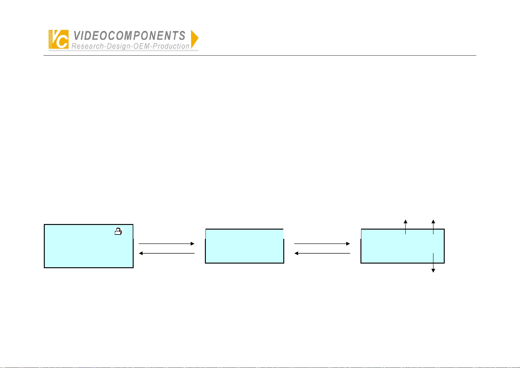
Simplified Illustration of Operation of System Controller VC-SC1000M
p
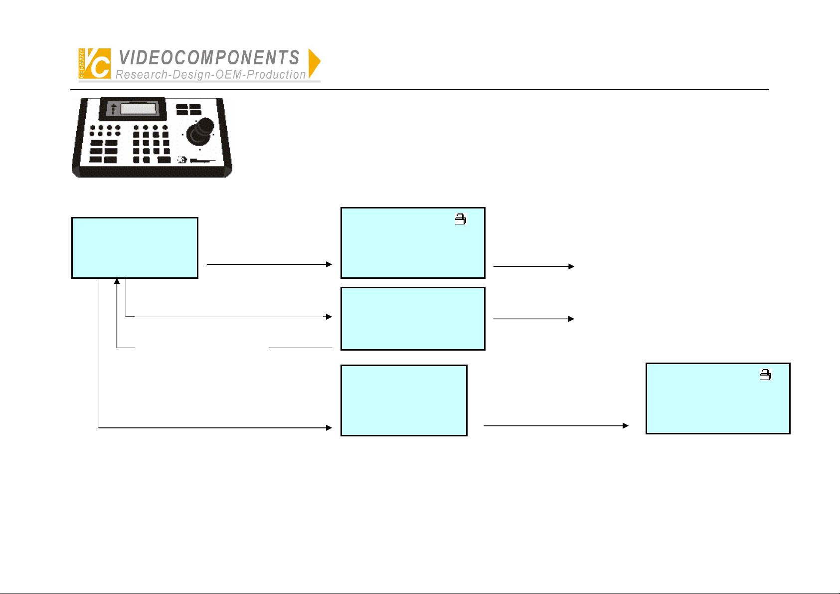
Simpilfied Illustration of Operation of System Controller
VC-SC1000M
● Matrix switcher
● Intelligent high-speed dome camera
Open (In 5 seconds)
SC1000M Ver02<0001-01>
**********************
System Control Keyboard
2)Press MODE and enter PC
communication surface:
Press any key to exit.
1)Press FUNC and enter
management system
o
eration:
Monitor: 001 Hold/Q
Camera: 0001 DISW PTZ
Alarm: 0001 Enable
22:26:35 04-08-2005 Fri.
****** Ver02<0001-01>
Communicate with PC
Can direct
controlled:
(Protocol is set up for VC ex-work)
● DVR (Press MODE to select DVR
then make acknowledgement)
● Multiplexer (Press MODE to select
multiplexer then make
acknowledgement)
Control is available by PC
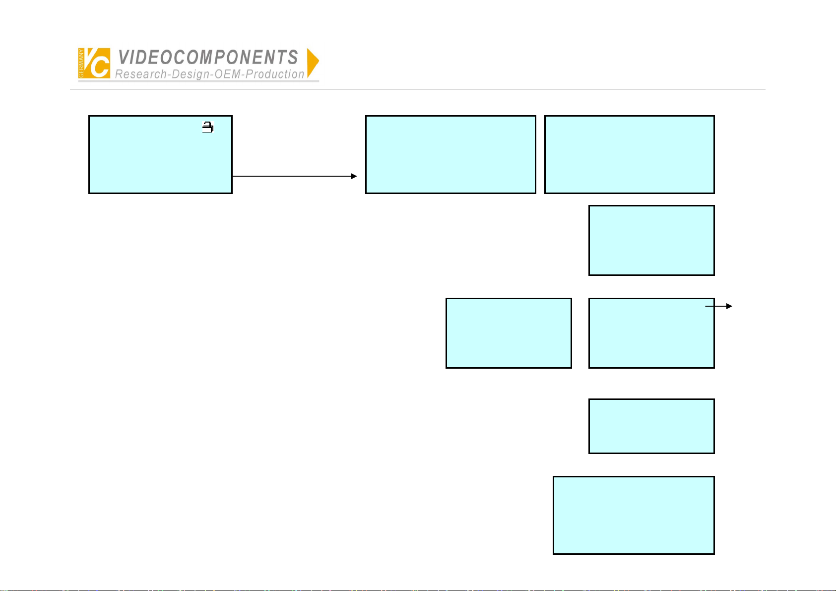
3)Press USER and enter logon surface:
Please Log On
User-ID:01-admin
Password:******
Logon Logout Exit
Rotate the joystick to select the
user’s ID and input the password
and then select LOGON to press
ENTER.
Monitor: 001 Hold/Q
Camera: 0001 DISW PTZ
Alarm: 0001 Enable
22:26:35 04-08-2005 Fri.
NOTE:
● Administrative authority of No.1 user has been set up ex-works. Password: 012345. (Other user’s ID has not been set up, which can not logon.)
● For the security, please alter the authority of No. user for operator after mastering the operation of the controller.
● so as to prevent non-administrator from logon by pressing rapid key FUNC or entering the menu by false operation to after the data of the controller.
● Remember that before alteration of the authority of No.1 user other No.of user should be set up otherwise entering the menu is unavailable. At that time, perform
initialization of the controller to recover the default administrative authority.
- 1 -
Page 3
Menu Setting
Simplified Illustration of Operation of System Controller VC-SC1000M
Monitor: 001 Hold/Q
Camera: 0001 DISW PTZ
Alarm: 0001 Enable
22:26:35 04-08-2005 Fri.
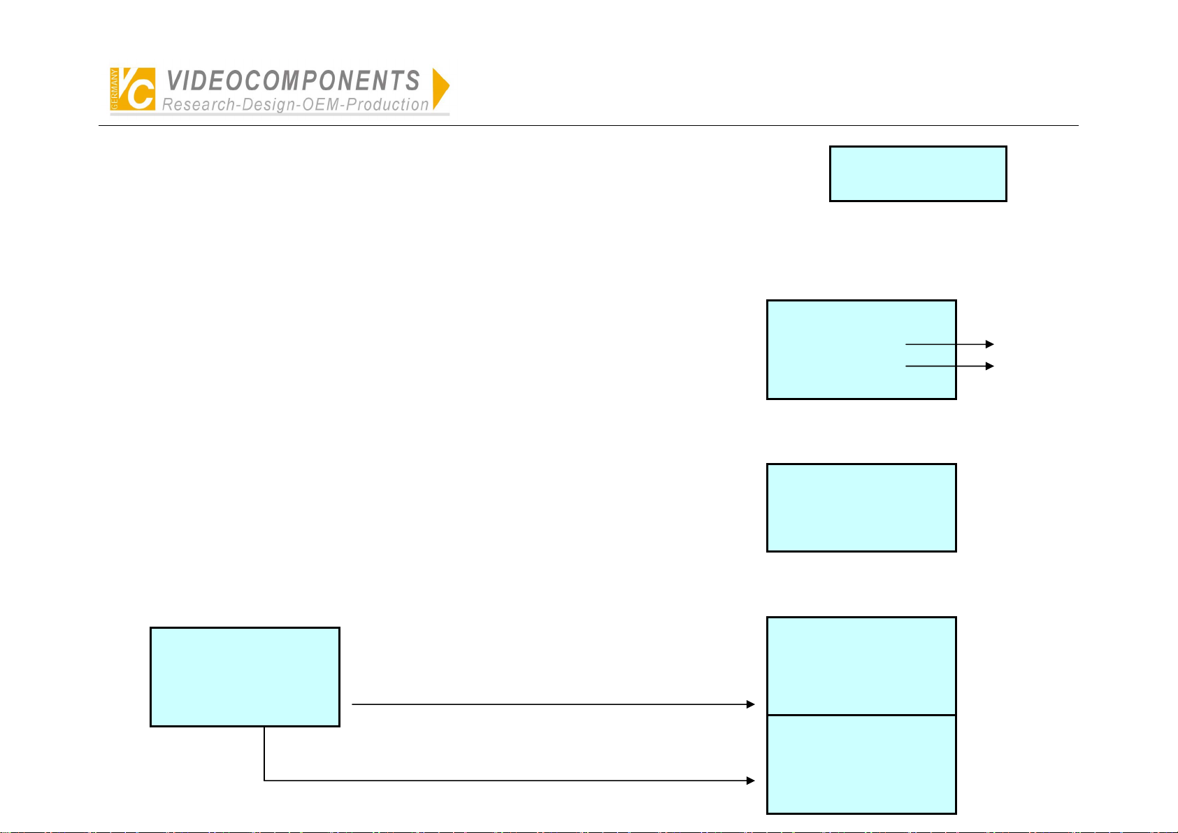
Press MENU and enter
the menu surface:
1. System-Capacity
2. Manage-Users
3. Keyboard-ID 4.Set-time
Next.> Off.Exit
1、 System-Capacity: Set up the largest capacity of controller cameras, monitors and alarms for the controller,
which will limit directly the following relevant data setting.
User-ID: 01-ADMIN
2、 Manage-Users: Set up the new user, password and its authority.
Password: 123456
Authority: ADMI Level: A
Next.> Off.Exit
3、 Keyboard-ID: Set up the controller’s ID, which is used recognize the controllers on bus of the matrix.
It is possible not to set up the same ID of the controller on the bus.
5.DVR/MULTI 6.Cam-PROT
7.Set Baud Rate 8.Set RF
9.Recover Default Info
Prev.< Off.Exit
MON-Capacity: 239
CAM-Capacity: 9999
ALM-Capacity: 9999
On.Save Off.Exit
MON-Range:000-239 A>
CAM-Range:0000-9999 A>
ALM-Range:0000-9999 A>
Prev.< Save Off.Exit
Set Key-ID: 01(01-32)
Save off. Exit
Set-time:
More groups can be
setup in each item.
4、 Set-time: Set up time, week and date, which will be transmitted to the matrix after exit of the menu.
- 2 -
HO:MI:SE MO-DA-Year WEEK
22 :26:35 04-08-2005 Fri
Page 4
Simplified Illustration of Operation of System Controller VC-SC1000M
5、 DVR/MULTI: Select the control protocol of DVR of Multiplexer.
Set DVR:
DVR: Select the protocol for the current DVR.
Protocol of VC, HIK has been set up ex-work. Default protocol is HIK. If any other protocol of DVR is required. Please contact the supplier.
MULTI: Select the protocol of the current multiplexer. Default protocol is VC. If any other protocol of multiplexer is required. Please contact the supplier.
6、 Cam-PROT: Select the control protocol of camera.
Protocol of VC, Pelco-P, Pelco-D, Panasonic, Samsung has been set up ex-works.
If any other protocol of camera is required. Please contact the supplier.
Set Cam Protocol:
For All Camera: **
Camera: 0001 **
Save Off. Exit
All camera protocol
One camera protocol
7、 Set Baud Rate: Set up band rate of external communication for the controller. 5 kinds of baud rate from 1200BPS to
19200BPS can be selected. Default baud rate is 9600BPS.
NOTE: The a.m. setting will get into effect after restart. Other setting becomes effect.
Set Baud Rate:
9600 Save Off.Exit
8、 Set RF: Set up wireless alarm and relay.
P/D-Alarm:0001
Camera:0001 Monitor:001
Prepoint:001 OT:3 CT:3
On.Save Off.Exit CLR.INI
Press SET and enter protocol surface of link-alarm.
Press SHOT and enter relay surface.
- 3 -
Alarm:0001
Cam Protocol: **
Baud Rate: 9600
On.Save Off.Exit
Alarm:0001
Relay Num: 001 002 003
004
On.Save Off.Exit
Page 5
Simplified Illustration of Operation of System Controller VC-SC1000M
NOTE:
● The a.m. setting can be performed by connection of front-end device. Other wise date can not read. Press any key to exit “Reading”.
● Under the state of No.2 main menu, press SHOT an enter the relay surface.
9、Restore Default Info: Recover default setting by password: 0123456789.
Password: **********
Confirm
Restore Default Info?
Yes No
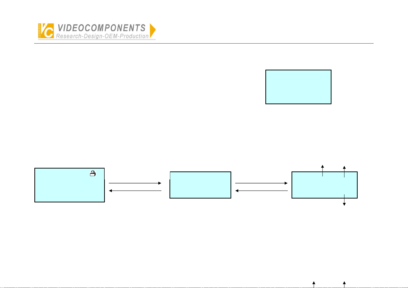
Multiplexer
1、 Press FUNC to switch multiplexer’s operating surface or front-end camera control surface.
Monitor: 001 Hold/Q
Camera: 0001 DISW PTZ
Alarm: 0001 Enable
22:26:35 04-08-2005 Fri.
Press FUNC and enter
Multiplexer’s control surface.
Press MUNE
Multiplex ID:01
22:26:35 04-08-2005 Fri.
Press FUNC and enter
front-end camera control
surface.
Press FUNC
ID of MUX
Multiplex ID:01 IN:01
PTZ CHANNEL:0001
22:26:35 04-08-2005 Fri.
Select input channel
No.of MUX by pressing
digit-key + ENTER
Input channel No.of MUX
responds to camera No.
2、 Under the state of multiplexer, press AUTOPAN to select ID of the current multiplexer. One who has administrative authority can set up the input channel No.of
multiplexer corresponding to front-end cameras.
- 4 -
ID of MUX
Input channel No. from
multiplexer to the matrix.
Page 6
Simplified Illustration of Operation of System Controller VC-SC1000M
DVR
1、 Press MODE to switch DVR’s operating surface or front-end camera control surface.
Monitor: 001 Hold/Q
Camera: 0001 DISW PTZ
Alarm: 0001 Enable
22:26:35 04-08-2005 Fri.
Press MODE and enter
DVR’s control surface
HIK DVR ID:01
22:26:35 04-08-2005 Fri.
Press MODE
Press MODE and enter
front-end camera control
surface
Press MODE
HIK DVR ID:01 IN:01
PTZ CHANNEL:0001
22:26:35 04-08-2005 Fri.
Input channel No.of DVR responds
to camera No.
Select the input channel
2、 Under the state of DVR, press NEXT to select ID of the current DVR. One who has administrative authority can set up the input channel No.of DVR
corresponding to front-end cameras.
- 5 -
Page 7

Simplified Illustration of Operation of System Controller VC-SC1000M
HIK DVR ID:01
22:26:35 04-08-2005 Fri.
Press NEXT for one time
Press NEXT for one
time
Set DVR ID:01 <00-66>
Save Off.Exit
by one who has
administrative authority.
Off.Exit Off.Exit
ID of DVR
Set DVR ID:01 <00-66>
MATRIX INPUT Cam NO.0001
DVR IN:01 SYS CAM:0001
Save Off.Exit
Input channel No. from
DVR to the matrix
Input channel No.
Input channel No.of DVR responds to camera No.
Inquiry Protocol of the Current Camera
Under the state of non-setting, press SET + CAM to display ID, control protocol and baud rate of external communication of the current camera.
Press any key to exit.
Current Camera: 0001
Cam Protocol: Pelco-D
Current Baud Rate: 9600
Other
There are three indicators (red, yellow, green) on the controller.
The red indicates the power, the yellow indicates receiving signal, the green indicates emitting signal.
The red will light when power is on, others will be glittering when the signal is received or emitted.
The movement up, down, left, right of the joystick can control the relevant action of the cameras. Rotate the joystick to control the zoom of lens.
- 6 -
Page 8

Simplified Illustration of Operation of System Controller VC-SC1000M
Camera protocol and baud rate are arranged in pairs as follows:
(Details see operation manual of the camera)
Pelco-P 2400bps/4800bps/9600bps/19200bps
Pelco-D
**
Panasonic
Samsung
2400bps/4800bps/9600bps/19200bp
9600bps
9600bps
9600bps
- 7 -
Page 9
Simplified Illustration of Operation of System Controller VC-SC1000M
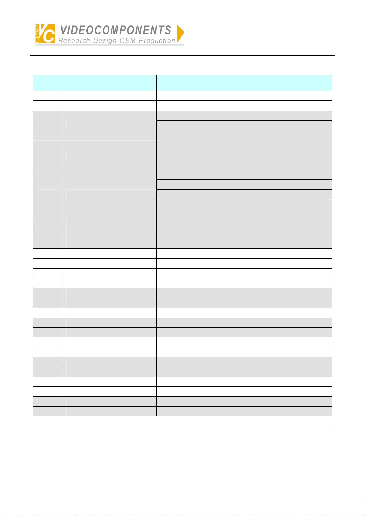
Description of Operation Keys of the Controller for VC Matrix for VC User
No. Keys of the controller Usage
1 ) MON+N+ENTER Select monitor(N=0~239)
2 ) CAM+N+ENTER Select camera
--N=0:Set up defence of current alarm
3 )* ON+MON+N+ENTER
4 )* OFF+MON+N+ENTER
5 ) GRP+N+ENTER
6 )* CAM+N+ON Insert camera in auto switching
7 )* CAM+N+OFF Delete camera in auto switching
8 )* MON+N+RUN Set up the dwell time of auto switching
9 ) RUN Run auto switching
10) HOLD Hold auto switching
11) PREV Manual previous switching
12) NEXT Manual next switching
13)* ALM+N+ON Set up defence of alarm
14)* ALM+N+OFF Dismantle defence of alarm
15) ALM+N+ENTER Query alarm status
16)* AUX+N+ON Open auxiliary relay
17)* AUX+N+OFF Close auxiliary relay
18) AUX+MON+OFF Lock current monitor
19) AUX+MON+ON Unlock current monitor
20)* ON+N+ENTER Close Relay No. n
21)* OFF+N+ENTER Open Relay No. n
22) STAR(*) Reply alarm info, etc
23) SHOT+MON+N+ENTER Access switching mode
24)* MON+MENU Enter Menu
25)* MON+ENTER Enter Sub Menu
NOTE: One who has authority of management can set up.
--N=1:Date&Time Display_On
--N=2:Address Info Display_On
--N=0:Dismantle defence of current alarm
--N=1:Date&Time Display_Off
--N=2:Address Info Display_Off
Access switching mode
--N=1~128: Program_Mode
--N=129: Sequence_Mode
--N=130: BackWard_Mode
--N=131~134:Group_Mode
- 8 -
Page 10

Simplified Illustration of Operation of System Controller VC-SC1000M
Description of Operation Keys of the Controller for VC Camera for VC User
No. Keys of the controller Usage
1) * SET+N+ENTER Set preset N
2) SHOT+N+ENTER Go To Preset N(N=0:Start Sequence Prepos)
3 )* SET+N+ON Insert Prepos In Stack
4 )* SET+N+OFF
5 )* SET+N+SET Set Stack Dwell time
6 )* SET+ON Set up AUTO_PANING Start LIMIT
7 )* SET+OFF Set up AUTO_PANING End LIMIT
8 )* SET+N+SHOT Set up speed of AUTO_PANING(N=1~9)
9 ) AUTOPAN Run AUTOPAN
10 ) ON+CAM+ENTER Unlock current camera
11) OFF+CAM+ENTER Lock current camera
12)* ON+CAM+N+ENTER Open CAM Auxiliary
13)* OFF+CAM+N+ENTER Close CAM Auxiliary
--N=0:Set up/Dismantle terminal alarm
Delete Prepos From Stack
--N=0: Delete all Prepos From Stack
For
12)&13)
14)* CAM+MENU Enter Camera Menu
15) CLOSE+N (simultaneously) CLOSE @ Speed N(N=1~9)
16) OPEN+N (simultaneously) OPEN @ Speed N(N=1~9)
17) NEAR+N (simultaneously) NEAR @ Speed N(N=1~9)
18) FAR+N (simultaneously) FAR @ Speed N(N=1~9)
19) TELE+N (simultaneously) TELE @ Speed N(N=1~9)
20) WIDE+N (simultaneously) WIDE @ Speed N(N=1~9)
21) SET+N+CLOSE+ENTER Set Close Speed N(1~9)
22) SET+N+OPEN+ENTER Set Open Speed N(1~9)
23) SET+N+NEAR+ENTER Set Near Speed N(1~9)
24) SET+N+FAR+ENTER Set Far Speed N(1~9)
25) SET+N+TELE+ENTER Set Tele Speed N(1~9)
26) SET+N+WIDE+ENTER Set Wide Speed N(1~9)
--N=9:Auto/Manual Focus
--N=10:Auto/Manual Iris
--N=1~8:Open/Close auxiliary Switch
NOTE: One who has authority of management can set up.
- 9 -
Page 11
Simplified Illustration of Operation of System Controller VC-SC1000M
Description of Operating Keys for Pelco-p & Pelco-d
No. Keys of the controller Usage
1) SET+N+ENTER Set Preset
2) CLR+N+ENTER Clear Preset
Go To Preset
--N=1~32:PRESET
--N=33: Flip (180° about)
--N=34: Go To Zero Pan
--N=92: Set Left Limit Stop
3) SHOT+N+ENTER
4) N+ON Set Auxiliary
5) N+OFF Clear Auxiliary
6) SET+CLR+ENTER Remote Reset
7) SET+N+ON Set Zone Start
8) SET+N+OFF Set Zone End
9) CLR+OFF Clear Screen
10) AUX+ON Zone Scan On
11) AUX+OFF Zone Scan Off
12) SET+ON Set Pattern Start
13) SET+OFF Set Pattern Stop
14) CAM+RUN Run Pattern
15) SET+N+ZOOM Set Zoom Speed (N=0~3)
16) SET+N+FOCUS; Set Focus Speed(N=0~3)
17) SET+RUN Start Sequence Prepos
18) ON+N+SET Insert Prepos In Stack
19) CLEAR+N+SET Delete Prepos From Stack
20)* OFF+SET Clear Seq. Stack
21) SHOT+SET Show Seq. Stack
22) SET+N+SET; Sequence dwell time(N=0~255)
23)* ON+N+OFF Home function
24) SET+N+AUTOPAN AUTO_PANING SPEED(N=0~255)
25) ON+N+AUTOPAN AUTO_PANING LIMIT(1LEFT/2RIGHT)
26) AUTOPAN AUTO_PANING START
--N=93: Set Right Limit Stop
--N=94: Remote Reset
--N=95: Enter Menu Mode
--N=96: Stop Scan
--N=97: Begin Random Scan
--N=98: Begin Frame Scan
--N=99: Begin Auto-scan
- 10 -
Page 12

Simplified Illustration of Operation of System Controller VC-SC1000M
27) SET+AUTOPAN+N+ENTER SET TILT SPEED(N=0~255)
28) SET+SET+AUTOPAN+N+ENTER
29) CAM+ON CAMERA ON
30) CAM+OFF CAMERA OFF
31) ON+AUTOPAN AUTO SCAN
32) OFF+AUTOPAN MANUAL SCAN
NOTE:
1. One who has authority of management can set up.
2. The protocol of non-original Pelco products is not as same as above protocol.
SET PAN SPEED(N=0~255)
(MUST SET PAN_SPEED FIRST THEN TILT_SPEED)
Please refer to the dome camera manual.
- 11 -
Page 13

Simplified Illustration of Operation of System Controller VC-SC1000M
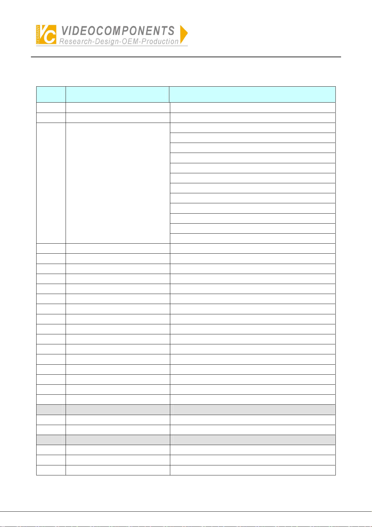
Description of Operating Keys for DVR of VC
Keys of the controller Usage Display
CLOSE/DEL Delete DEL
ALM Record RECORD
ON Play PLAYBACK
SET Set up SETUP
SHOT Back up BACKUP
NEAR Format PIC_FORMAT
1 1 D1
2 2 D2
3 3 D3
4 4 D4
5 5 D5
6 6 D6
7 7 D7
8 8 D8
9 9 D9
0 0 D0
FAR Switching PIC_LOOP
MON Chinese CHINA
CAM point POINT
WIDE/PgUp Previous page PAGEUP
TELE/PgDn Next page PAGEDOWN
Joystick UP Up UP
Joystick DOWN Down DOWN
Joystick LEFT Left LEFT
Joystick RIGHT Right RIGHT
OPEN/BACK Return BACK
ENTER Acknowledgment ENTER
AUX Frame progress FRAME
OFF Fast forward FORWARD
GRP Fast reword BACKWARD
AUTOPAN Pause PAUSE
CLR Alarm clear ALARM_CLEAR
* Information INFO
HOLD lock LOCK
- 12 -
Page 14
Simplified Illustration of Operation of System Controller VC-SC1000M
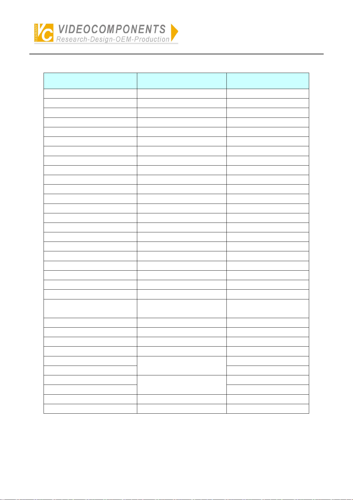
Description of Operating Keys for DVR of HIK
Keys of the controller Usage Display
Joystick UP Up UP
Joystick DOWN Down DOWN
Joystick LEFT Left LEFT
Joystick RIGHT Right RIGHT
0+1 1 1
0+2 2 2
0+3 3 3
0+4 4 4
0+5 5 5
0+6 6 6
0+7 7 7
0+8 8 8
0+9 9 9
1+0 10 10
1+1 11 11
1+2 12 12
1+3 12 13
1+4 14 14
1+5 15 15
1+6 16 16
AUTOPAN Editing EDIT
PREV Multiples display VIEW
AUX Display channels of camera
inputs of DVR
ON Play PLAY
ALM Record REC
CAM P/T control PAN
SET System menu MENU
Joystick UP UP
Joystick DOWN
Joystick LEFT LEFT
Joystick RIGHT
ENTER Acknowledgement ENTER
CLEAR Exit ESC
Alter setting
Select items of setting
A
DOWN
RIGHT
- 13 -
Page 15
Simplified Illustration of Operation of System Controller VC-SC1000M
Description of Operating Keys for Multiplexer of ROBOT
Keys of the controller Usage Display
UP Up UP
DOWN Down DOWN
LEFT Decrease DEC
RIGHT Increase INC
ENTER Acknowledgement ENTER
CLEAR Exit EXIT
SET Menu MENU
RUN Picture in picture PIP
MON Call back CALL
NEXT Switching SEQ
CLOSE Play PLAY
TELE Zoom ZOOM
HOLD Frozen FROZEN
OPEN 2*2 2*2
FAR 3*3 3*3
WIDE 4*4 4*4
1 1 1
2 2 2
3 3 3
4 4 4
5 5 5
6 6 6
7 7 7
8 8 8
9 9 9
10 10 10
11 11 11
12 12 12
13 13 13
14 14 14
15 15 15
16 16 16
* Chooses digit --/-
Note: Under the mode of multiplexer, there are 16 frames of pictures.
Press ‘*’ to select unit frame. Press ‘*’ to select Two-digits frames.
- 14 -
Page 16
Simplified Illustration of Operation of System Controller VC-SC1000M
Description of Operating Keys for Intelligent Dome Camera of SAMSUNG
No.
1 ) 0+ENTER K_0
2 ) 1+ENTER K_1
3 ) 2+ENTER K_2
4 ) 3+ENTER K_3
5 ) 4+ENTER K_4
6 ) 5+ENTER K_5
7 ) 6+ENTER K_6
8 ) 7+ENTER K_7
9 ) 8+ENTER K_8
10) 9+ENTER K_9
11) ON+GRP SCAN_START
12) OFF+GRP SCAN_STOP
13)* ON+SET MENU_ON
14)* OFF+SET MENU_OFF
15) ENTER ENTER
16) SHOT+N+ENTER PRESET_MOVE(N=0~127)
17) ON+AUTOPAN AUTOPAN_START
18) OFF+AUTOPAN AUTOPAN_STOP
19) ON+N+AUX PATTERN_START(N=0~3)
20) OFF+N+AUX PATTERN_STOP(N=0~3)
21) 0+CLEAR+SET RESET
22) 100+CLEAR+SET FACTORY_RESET
23) SET+N+ENTER PRESET_SAVE(N=0~127)
24) CLEAR+N+ENTER PRESET_DELETE(N=0~127)
25) 1+FAR ONE FAR
NOTE:
Keys of the controller Usage
One who has authority of management can set up.
- 15 -
Page 17
Simplified Illustration of Operation of System Controller VC-SC1000M
Description of Operating Keys for Intelligent Dome Camera of PANASONIC
NO
1 SHOT+N+ENTER
2 ON+AUTOPAN AUTO PAN ON
3 OFF+AUTOPAN AUTO PAN OFF
4* 1+AUTOPAN AUTO PAN SPEED INC
5* 2+AUTOPAN AUTO PAN SPEED DEC
6* 3+AUTOPAN AUTO PAN START POINT SET
7* 4+AUTOPAN AUTO PAN END POINT SET
8* 5+AUTOPAN AUTO MODE OFF
9* 6+AUTOPAN AUTO SEQ ON
10* 7+AUTOPAN AUTO SORT ON
11* 8+AUTOPAN AUTO PAN SWEEP AREA INVERT
12* 1+ON ENDLESS ON
13* 1+OFF ENDLESS OFF
14* 2+ON DIGITAL FLIP ON
15* 2+OFF DIGITAL FLIP OFF
16* 3+ON PROPORTIONAL P/T ON
17* 3+OFF PROPORTIONAL P/T OFF
18 4+ON SUPER-DII ON
19 4+OFF SUPER-DII OFF
Keys of the
controller
Usage Function
PRESET 1 CALL
PRESET 2 CALL
~
PRESET 63 CALL
PRESET 64 CALL
PRESET CALL
AUTO PAN
AUTO MODE
ENDLESS
DIGITAL FLIP
PROPO.P/T
SUPER-DII
20* 5+ON
21* 5+OFF
22* 5+SHOT 1 SHOT AF ON (START)
23* 6+ON HOME POSITION MOVE HOME POSITION
24* 7+ON
25* 7+OFF
26* 7+SET
27* 8+ON CAMERA ID ON
28* 8+OFF CAMERA ID OFF
STOP AF ON (MENU ITEM)
STOP AF OFF (MENU ITEM)
BW ON (MENU ITEM)
BW OFF (MENU ITEM)
BW AUTO (MENU ITEM)
AF
BW
CAMERA ID
- 16 -
Page 18

Simplified Illustration of Operation of System Controller VC-SC1000M
29* 9+ON+SET AREA TITLE NESW ON
30* 9+ON_SHOT AREA TITLE USER ON
31* 9+OFF AREA TITLE OFF
32* 10+ON EL-ZOOM ON
33* 10+OFF EL-ZOOM OFF
34* 11+ON REFRESH REFRESH
PRESET1 SET
PRESET2 SET
AREA TITLE
EL-ZOOM
35* SET+N+ENTER
36 12+ON PATROL PLAY
37 12+OFF PATROL STOP
38* 12+SET PAT RO L LEARN
39 OPEN IRIS OPEN
40 CLOSE IRIS CLOSE
41 IRIS+FREE IRIS STOP
42* 0+IRIS IRIS RESET
43 13+ON SHUTTER ON SHUTTER
44 13+OFF SHUTTER OFF
45 13+TELE SHUTTER INC
46 13+WIDE SHUTTER DEC
47 14+ON AGC ON
48 14+OFF AGC OFF
49* 15+ON SENS UP FIX ON
50* 15+OFF SENS UP FIX OFF
51* 15+TELE SENS UP FIX INC
52* 15+WIDE SENS UP FIX DEC
53* 16+ON SENS UP AUTO ON
54* 16+OFF SENS UP AUTO OFF
55* 16+TELE SENS UP AUTO INC
56* 16+WIDE SENS UP AUTO DEC
57* 17+TELE LL Phase INC
58* 17+WIDE LL Phase DEC
59* 18+ON 180 deg pan turn
60* 19+ON CLEANING ON (MENU)
61* 19+OFF CLEANING OFF (MENU)
62* 0+AUX+ON AUX ALL ON
~
PRESET63 SET
PRESET64 SET
PRESET STORE
PATR OL
IRIS
AGC
SENS UP FIX
SENS UP AUTO
LL phase
180 deg pan turn
CLEANING
RECEIVER
FUNCTION
COMMAN
- 17 -
Page 19
Simplified Illustration of Operation of System Controller VC-SC1000M
63* 0+AUX+OFF AUX ALL OFF
64* 1+AUX+ON AUX 1 ON
65* 1+AUX+OFF AUX 1 OFF
66* 2+AUX+ON AUX 2 ON
67* 2+AUX+OFF AUX 2 OFF
68* 1+AUX+SHOT AUX 1 MOMENTARY
69* 1+AUX+SET AUX 1 LATCH
70* 2+AUX+SHOT AUX 2 MOMENTARY
71* 2+AUX+SET AUX 2 LATCH
72* *+CAM+SET SETUP MENU ON
73* *+CAM+CLR SETUP MENU OFF
74* 0+SET SETUP MENU [Cursor STOP]
75* JOYSTICK_UP SETUP MENU [Cursor UP]
76* JOYSTICK_RIGHT SETUP MENU [Cursor Right]
77* JOYSTICK_DOWN SETUP MENU [Cursor Down]
78* JOYSTICK_LEFT SETUP MENU [Cursor Left]
79* ENTER SETUP MENU SET1
80* CLR SETUP MENU SET2
81* 1+CAM+SET SETUP MENU SW (RESET)
82* 0+CAM+SET SETUP MENU SW (ALL RESET)
83* 0+CAM+ON Menu ON
84* 0+CAM+OFF Menu OFF
MENU
- 18 -
Page 20

GERMANY
C
R
Installations- und Betriebsanleitung
C
Your local distributor
All contents of this document may change without prior notice
All rights are reserved.
Änderungen in Technik, Design und Ausstattung vorbehalten
MO_14511-K
 Loading...